Dynamic Analysis of Composite Wind Turbine Blades as Beams: An Analytical and Numerical Study


1
Department of Mechanical Engineering, Imperial College London, London SW7 2AZ, UK
2
Faculty of Mechanical Engineering, Istanbul Technical University, Istanbul 34437, Turkey
3
Department of Aerospace Engineering, University of Bristol, Bristol BS8 1TR, UK
*
Authors to whom correspondence should be addressed.
Vibration 2021, 4(1), 1-15; https://0-doi-org.brum.beds.ac.uk/10.3390/vibration4010001
Submission received: 29 October 2020
/
Revised: 9 December 2020
/
Accepted: 21 December 2020
/
Published: 24 December 2020
(This article belongs to the Special Issue Dynamics of Composite Wind Turbine Rotor Blades)
Abstract
:This study focuses on the dynamic modelling and analysis of the wind turbine blades made of multiple layers of fibre reinforced composites and core materials. For this purpose, a novel three-dimensional analytical straight beam model for blades is formulated. This model assumes that the beam is made of functionally graded material (FGM) and has a variable and asymmetrical cross section. In this model, the blades are assumed to be thin, slender and long with a relatively straight axis. They have two main parts, namely the core and the shell. The so-called core consists of a lightweight isotropic foam material, which also adds significant damping to the system. The core material is covered by the shell, which is modelled using homogenous and orthotropic material assumptions as the structure is reinforced with continuous fibres. Therefore, the blades are modelled under a straight beam with varying cross-section assumptions, in which the effective elastic properties are acquired by homogenizing the cross section. The beam formulation for modelling the system is performed both analytically and numerically with the finite element method. The results of both methods are in well agreement. The maximum deviation between the results is found below 4%.
1. Introduction
The demand for energy increases day by day as the human population and industry grow fast. This continuous growth has brought the problem of sourcing the energy from the least environment-harming methods, in other words, sustainably. As one of the most popular sustainable methods, electrical energy production using kinetic energy of the wind is encouraged all around the world. Even though wind energy is relatively more sustainable, more environment-friendly than many of the commonly used energy generation methods, it may not be very cost-effective. For instance, the initial investment costs of wind turbines are generally very high. The energy generation outcomes and reliability issues of the wind turbines also make their feasibility challenging.
Larger blades and higher towers are required to increase the capacity of wind turbines [1]. However, the growing size of wind turbines makes the design process of these structures harder as the length/thickness ratio of the blades and the tower makes them too slender so that even their own weights become significant [2]. Thus, lightweight designs are found to be more effective in energy generation. To achieve such light and strong structures, composite materials usually become the best fits [1,3,4,5]. Blades usually are made of a strong and stiff shell as the skin and a stiffener web or lightweight core material. This structure reduces weight while preserving strength [1,6].
Among all components of the turbine structure, the blade is the most crucial part that requires extra care due to its slender geometry and the loads on itself [7]. Therefore, the modelling of the wind turbine blades is a major part of the design process of the blades. Early modelling studies usually include numerical methods such as the finite element method (FEM) since it can be considered the most general and complicated cases with acceptable approximations [8,9]. The loading combinations acting on the blade and consequently the stress-states that occur in the beam are quite complicated and vary along the beam axis. Thus, FEM becomes a very useful standardised method that can handle such complexities. Alongside these complexities, there are also aerodynamic/aeroelastic aspects of the actual blade. They usually limit the structural design of the blades and must be adapted accordingly to meet these complex requirements. Aerodynamics usually limits the outer form of the blade, and hence the structural improvements should be done with the materials rather than the geometry. Moreover, the major structural concern is often the fatigue issues, in order to ensure a reliable operation of wind turbines [6,10]. Therefore, wind loads should not excite the vibration modes of the blades to avoid excessive vibration displacements [11]. Briefly, the structural dynamic and aeroelastic behaviour of wind turbines should be considered during their design process [12,13,14].
With the consideration of the geometry of the blades, the beam or shell elements can be used instead of three-dimensional tetrahedral or hexahedral elements for predicting mechanical behaviour, as this can reduce the computational cost without affecting accuracy significantly [15]. On the other hand, shells are usually more representative of the outer stiff, layered structure of the blades [16]. For these reasons, shells are usually more accurate in the modelling of blades than beams since the shells represent the deformations of the cross section with better rightness [17]. The disadvantage of using shell models is their having more degrees of freedom than the beam models, making it computationally more expensive. To reduce the computational cost of using shells as well as the error that symmetric isotropic and homogeneous beams cause, more advanced beam formulations that are specifically designated to model certain structures, such as propellers and wind turbine blades by taking into account axial loading, shear deformations etc., are developed [16,18,19,20].
Apart from FEM, there are other numerical models using various improved beam theories for the representation of rotor blades that consider the variation of the cross-sectional, material properties and the loads acting on the structure [21,22,23]. As mentioned earlier, the most common beam modelling approaches consider only the cases with symmetrical cross sections and homogeneous and isotropic material. However, the blades have varying cross sections, and the composite materials used in the wind turbine blades usually consist of fibre reinforced polymers. These composites are strongly orthotropic with changing orientation angles of the reinforcing fibres along the beam axis. Such structures are called tow steered composites [24,25,26]. Although the wind turbine blades usually undergo large deformations, the most common beam formulations, namely the Euler–Bernoulli and Timoshenko beam theories for straight and uniform beams, only include small displacements. Under these assumptions, performing analytical solutions even for frames are possible [27]. To build accurate models of the wind turbine blades, more general formulations that can take into account the characteristics of the blades must be considered, both geometrically and material-wise [28,29]. It is possible to identify the complexities of wind turbine blades in two main groups as geometrical and material. The large displacements, the mechanical systems may undergo, as well as the arbitrary and varying cross sections, that the beams may have, can be included within the geometric complexities. On the other hand, changing material behaviour with the position and direction (functionally graded material (FGM) and orthotropy/anisotropy) belong to the material category.
Since the wind turbine blades are made of fibre-reinforced composites, they can behave as orthotropic beams [30,31]. Higher-order beam models are capable of representing the laminated orthotropic beams and besides, as they allow for analytical solutions for certain conditions [32]. Another way to solve orthotropic beams analytically is the elasticity approach [33]. When the analytical solutions are not performable, numerical methods such as the finite difference method can also be used for solving these problems [34]. Moreover, material properties vary depending not only on the direction but also on the position in a continuum, which can be expressed with a function formulated in space. As mentioned earlier, such materials are called FGM. Inside the beams, material properties may vary throughout the thickness and/or along the axis [35,36]. Even though the material properties are not constant, analytical solutions can be performed and are available in the literature [37,38].
The geometric complexities can originate from the large displacements that the blades display, as well as from the cross sections being asymmetrical and varying through the axis. Large displacements and rotations lead to nonlinear terms in the equations of motion of the beams. Thus, only some limited cases are analytically solvable [39,40]. These nonlinearities are also considered for the analytical solutions of composite beams in the literature [41,42,43]. Furthermore, varying cross sections decisively affect the stiffness of the whole beams, and arbitrary cross sections lead to coupling of different vibration and buckling modes (flexural and torsional) [44,45]. For the composite wind turbine blades, the shape of the cross section is complex, and the material properties vary, depending on the position throughout the thickness of the beam and along the axis of the beam. This of course influences the shear behaviour of the beam [46,47]. Multiple methods exist to extract cross-sectional properties [48,49,50,51].
After covering the literature on modelling of composite beams and blades, it can be claimed that there is limited research concerning beams that are made of functionally graded material (FGM) with a varying and asymmetrical cross section. In this study, a novel analytical three-dimensional straight beam model with a varying cross section made of axially FGM is formulated. Then, its modal analysis is done analytically. This beam model considers asymmetrical cross sections where is nonzero. The cross-sectional properties, as well as the elastic properties, namely Young’s and shear moduli, are acquired using a three-dimensional finite element model and an open-source computer code, i.e., BECAS (Beam Cross-section Analysis Software), that can run on GNU Octave, also an open-source software [52,53]. Finally, the novel analytical formulation of the three-dimensional straight beam is validated with the modal analysis results of the three-dimensional finite element model.
2. Dynamic Modelling of Composite Wind Turbine Blades
Throughout this study, the DTU-10MW-RWT blade, which is shown in Figure 1, is selected as a reference model [54]. This blade is 86.3 m in length and is made of uniaxial, biaxial, and triaxial laminates with a balsa core.
In this section, both analytical and finite element models of the composite wind turbine blades are presented. Rotational speed effects were not considered in the modelling. Therefore, gyroscopic and centrifugal stiffening effects on the dynamic behaviour of the wind turbine blade are not included within the scope of this study.
2.1. Analytical Model
An analytical formulation for a straight beam with a varying cross section and made of functionally graded material is presented for modelling wind turbine blades. This formulation assumes that the beam has a perfectly straight axis and an asymmetrical, rigid and homogeneous cross section. Considering the geometry of the blade, these assumptions are not expected to introduce a significant amount of error on the natural frequencies.
To keep the beam model linear, the beam is divided into multiple regions, where the variations of cross-sectional and material properties can be neglected and the average values of these varying quantities are used for each region. Then, the system can be fully defined and solved analytically using the compatibility conditions between the regions.
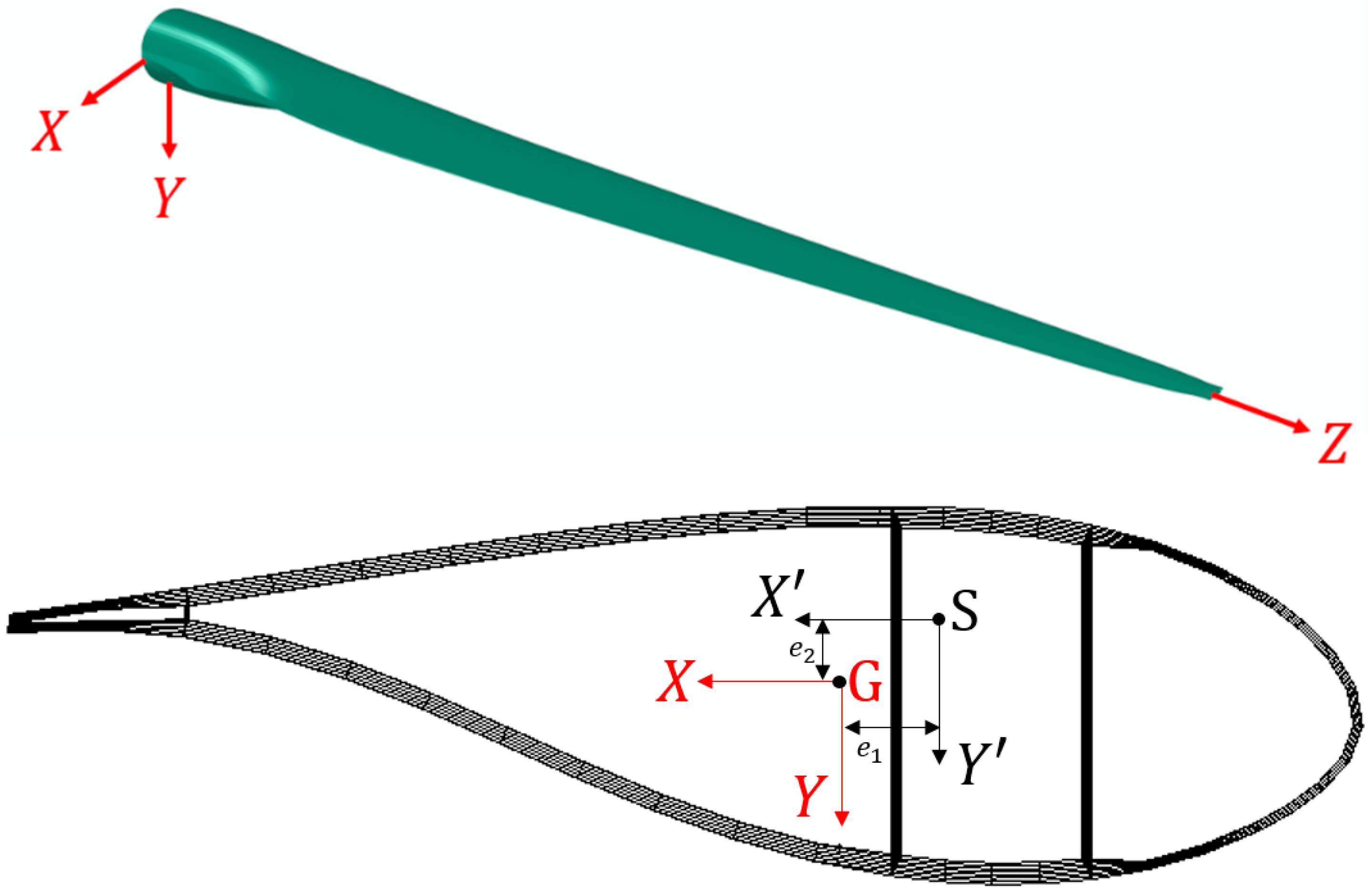
The coordinate system used in the formulation is presented in Figure 2. Here, the coordinate system is attached to , the centre of mass (CM); the coordinate system is attached to , the shear centre (SC); and are distances between , i.e., the coordinates of the centre of mass, and , coordinates of the shear centre.
In the analytical formulation, the equilibrium and compatibility equations in Reference [27] are modified for the beam, which has a nonuniform and asymmetrical cross section. The equilibrium equations are
where , and are distributed forces; , and are distributed moments; , and are internal forces; and , and are internal moments.
The compatibility equations for the beam can then be written as
where , , and are translational displacements; , , and are angular displacements; , , and are relative angles for a unit length of the beam; and , , and are shear angles.
Under linear, elastic, and isotropic material assumptions, the constitutive equation can be written in the matrix form as follow:
Here, is the area; and are the moment of inertias around and axes at the centre of mass (CM); is the product-moment of inertia at CM; is the torsional constant; is the effective Young modulus; is the effective shear modulus; and and are shear correction factors around and axes, respectively.
Finally, by combining Equations (7)–(12) and Equations (13) and (14), the following equations are obtained as:
To obtain the eigenvalue problem, D’Alembert’s principle is employed, and the distributed forces and distributed moments in Equations (1)–(6) are replaced by the inertia terms:
Here, is the polar moment of inertia at CM, and is the mass per length. Under the harmonic vibration assumption, Equations (21)–(26) can be rewritten as
where represents the angular frequency. By substituting Equations (27)–(32) into Equations (1)–(6) and writing them together with Equations (15)–(20) in matrix form, a system of differential equations is then obtained as
where is written as
and matrix is given in Appendix A. The exact solution of the system of differential equations in the Equation (33) can be obtained only with constant cross-sectional and material properties. However, the blade has varying properties as mentioned earlier. Therefore, the blade is divided into several regions, assuming each region possesses constant cross-sectional and material properties. The varying properties of the beam are averaged using the average value theorem as given in Equation (35).
Here, is the function to be averaged; and are the start and endpoints of the region , respectively; and is the average value of the function .
The exact solution of Equation (33) is known as
Here, is the initial values vector. Following an algebraic set of equations are obtained as
by applying boundary and continuity conditions. Finally, the determinant of the coefficient matrix in the Equation (37) must be equal to zero for nontrivial solutions. The natural frequencies of the structure are obtained.
2.2. Finite Element Model
The finite element method is a useful tool for the dynamic modelling of complex structures. In addition, computer models created by using this method can then be imported into other programs such as Abaqus (Dassault Systémes, Vélizy-Villacoublay, France) for the finite element analyses and BECAS for the computation of geometry/material properties. Here, to validate the abovementioned formulation and create an input for BECAS, the finite element model of the blade provided by [52] was used.
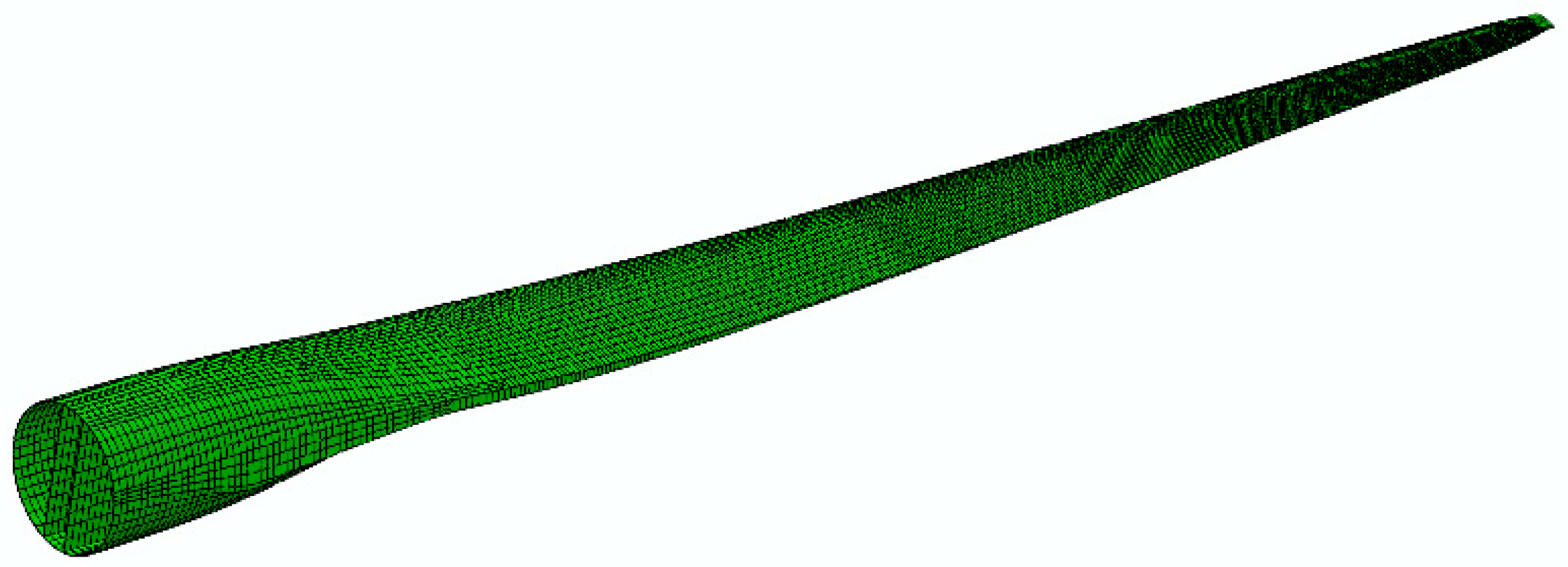
The finite element model of the composite wind turbine blade was created with shell elements in Abaqus (Dassault Systémes, Vélizy-Villacoublay, France). To create the mesh structure, the eight-node shell elements with reduced integration (S8R) were used. The mesh structure of the composite blade is shown in Figure 3.
The model consists of eleven different regions and for each region, various composite layups are created by defining the region, material, thickness, and orientation of each ply. As boundary condition, it is assumed that the blade is fixed at its root.
3. Results
3.1. Structural Properties of the Blade
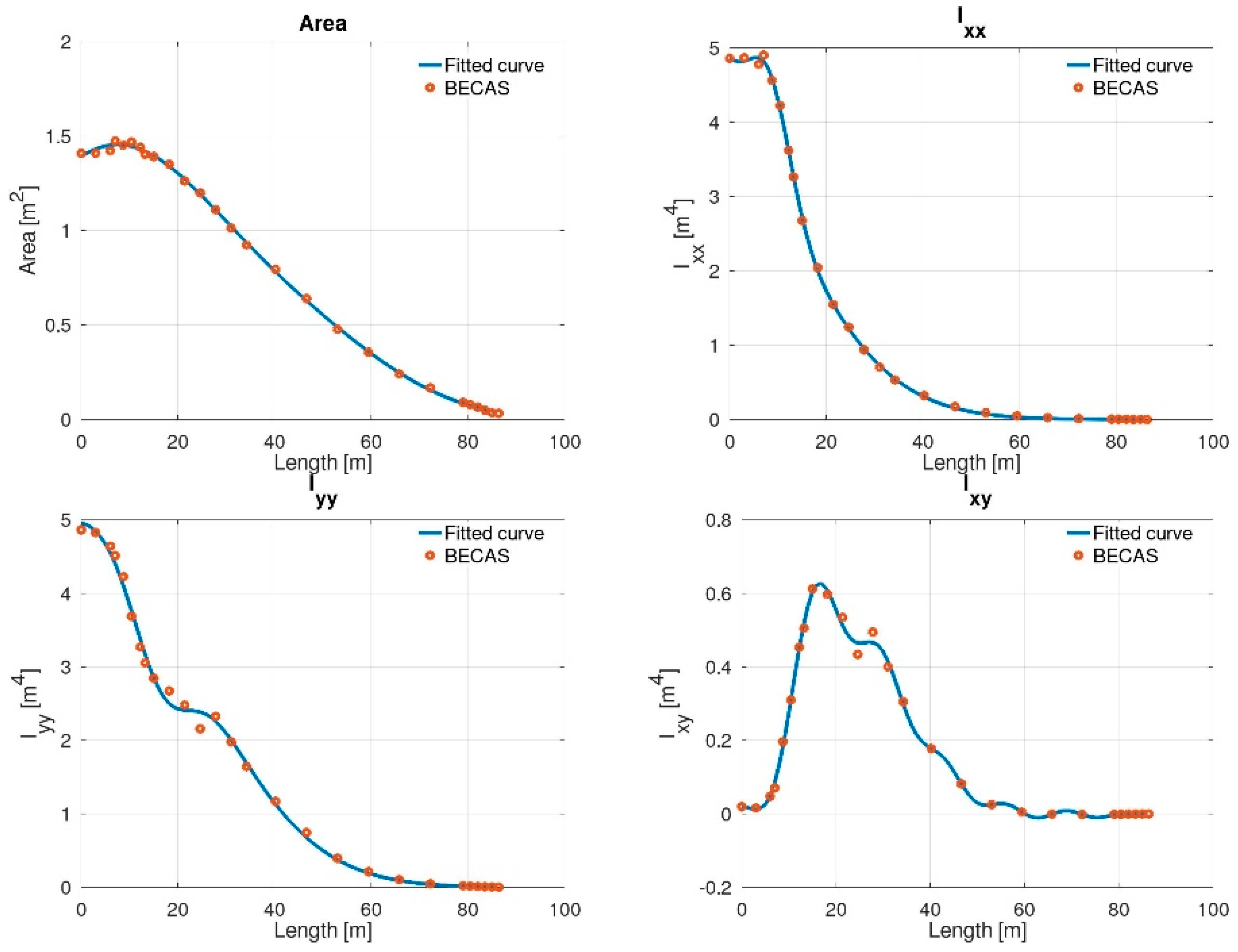
In composite structures, the geometry of the cross section is related to the number of layers and the thickness of each layer. Therefore, cross-sectional properties such as the area, the area moment of inertia, and the torsional constant should be computed accurately by considering these dimensional properties of the composite structure. To analyse the anisotropic and arbitrary-shaped beam cross sections, the open-source software BECAS was employed [52]. For 27 different coordinates, the required cross-sectional and material properties were obtained from BECAS, and these properties are expressed as continuous functions by applying curve-fitting process in GNU Octave. Functions used in the curve-fitting process are given in Appendix B. This can be clearly seen from Figure 4, Figure 5 and Figure 6; the fitted curves and BECAS data are in good agreement with each other.
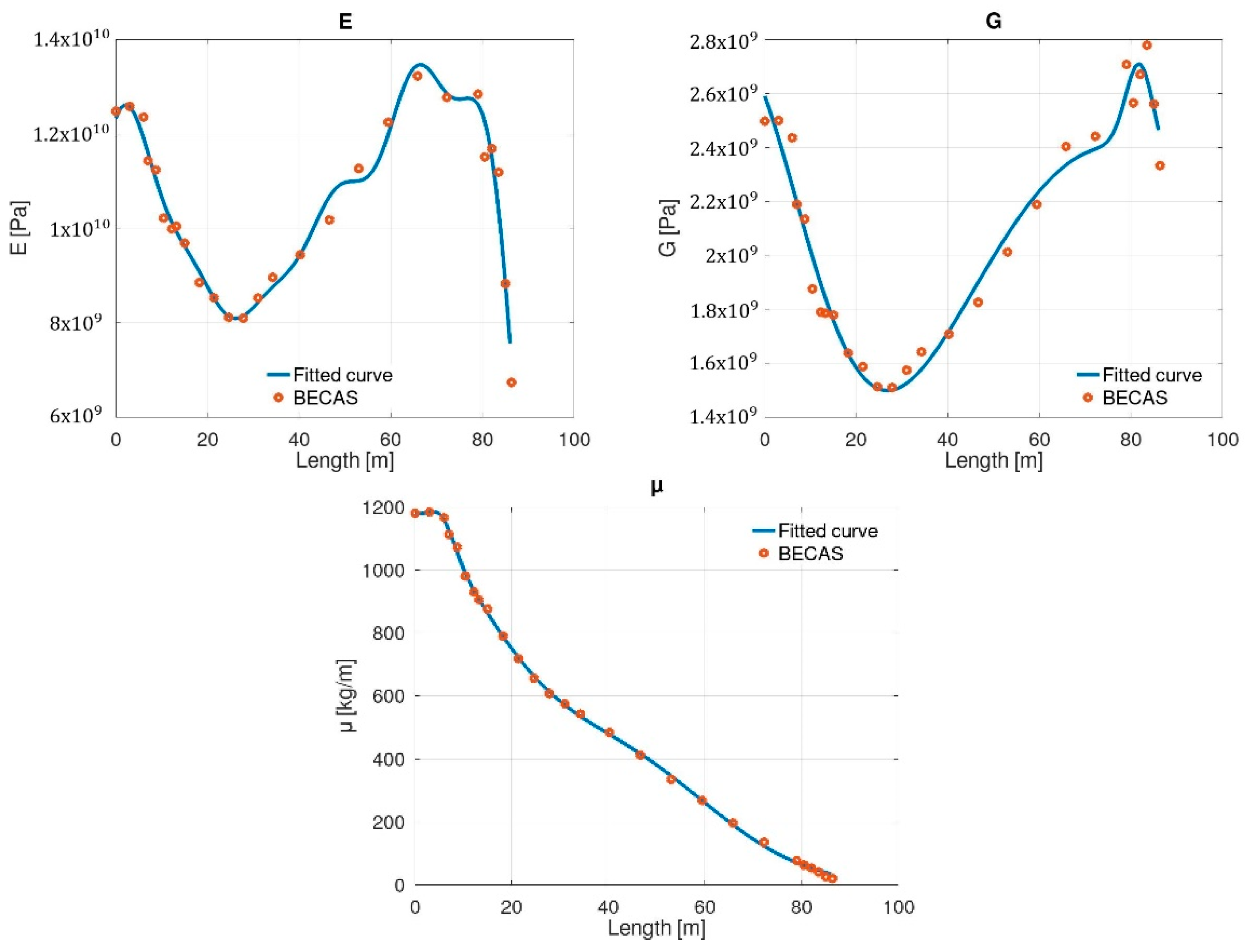
Figure 4 clearly shows that there is a downward trend along the beam axis in the , and parameters, while increases until a certain length, approximately at 20 m. Surprisingly, starts to decrease after that point. In Figure 5, it should be noted that reaches the maximum value at the blade tip; the same location is a minimum point for . In addition, there are significant fluctuations in the effective Young and shear moduli along the beam axis, which can be seen from Figure 6. It was noted that these values start from relatively high values and reach their minimum between 20 and 40 m. It was also observed that there is a significant decrease in the effective Young modulus at the blade tip. The mass per length () has almost the same tendency with the area () along the beam axis.
3.2. Modal Analysis
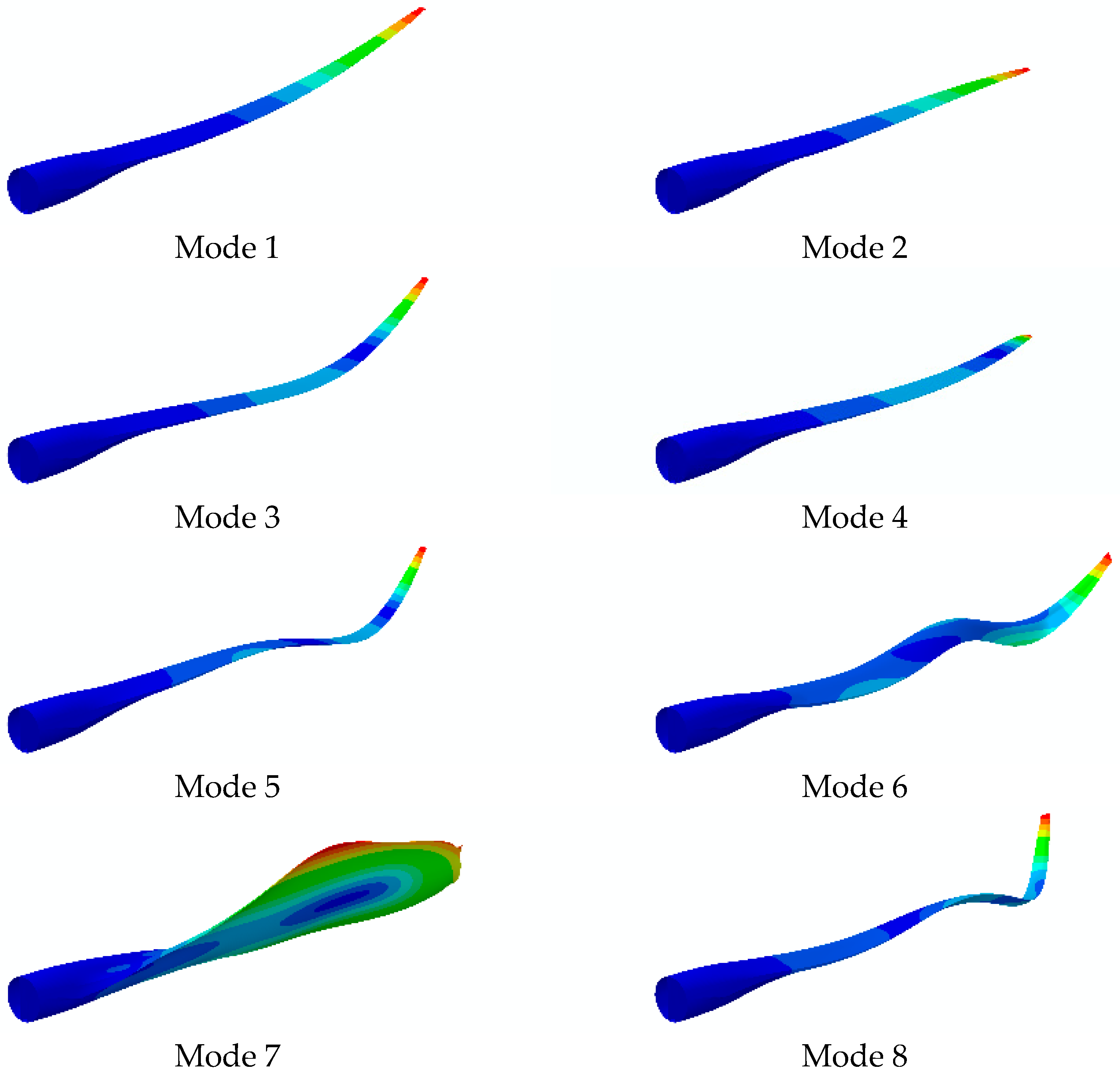
Analytically, the first eight vibration modes of the composite blade were obtained after applying the analytical formulation using the generated curve-fitted functions as the cross-sectional and material properties for 500 regions along the beam axis. Similarly, the finite element modal analysis of the composite beam was also performed using the finite element software Abaqus (Dassault Systémes, Vélizy-Villacoublay, France). The analytical and finite element modal analysis results are presented in Table 1.
Based on analytical and FEM modal analyses, the vibration modes of the composite blade were identified as either flapwise bending, edgewise bending, coupled flapwise-edgewise bending, or torsional. The flapwise bending mode can be expressed as the bending mode about axis. Similarly, the edgewise bending mode is the bending mode about axis. The coupled flapwise-edgewise bending mode can be considered as a combination of the flapwise and edgewise bending modes, and it occurs in 3D space. The torsional mode can also be defined as the twist-dominant mode along axis. The first eight mode shapes of the reference blade were visualised using the finite element software Abaqus (Dassault Systémes, Vélizy-Villacoublay, France), as seen in Figure 7.
As can be seen from Table 1, the results of both analytical and finite element methods are in excellent agreement with the maximum error of approximately 3%. It was observed that the natural frequencies obtained with the analytical method are slightly higher than the FEM ones.
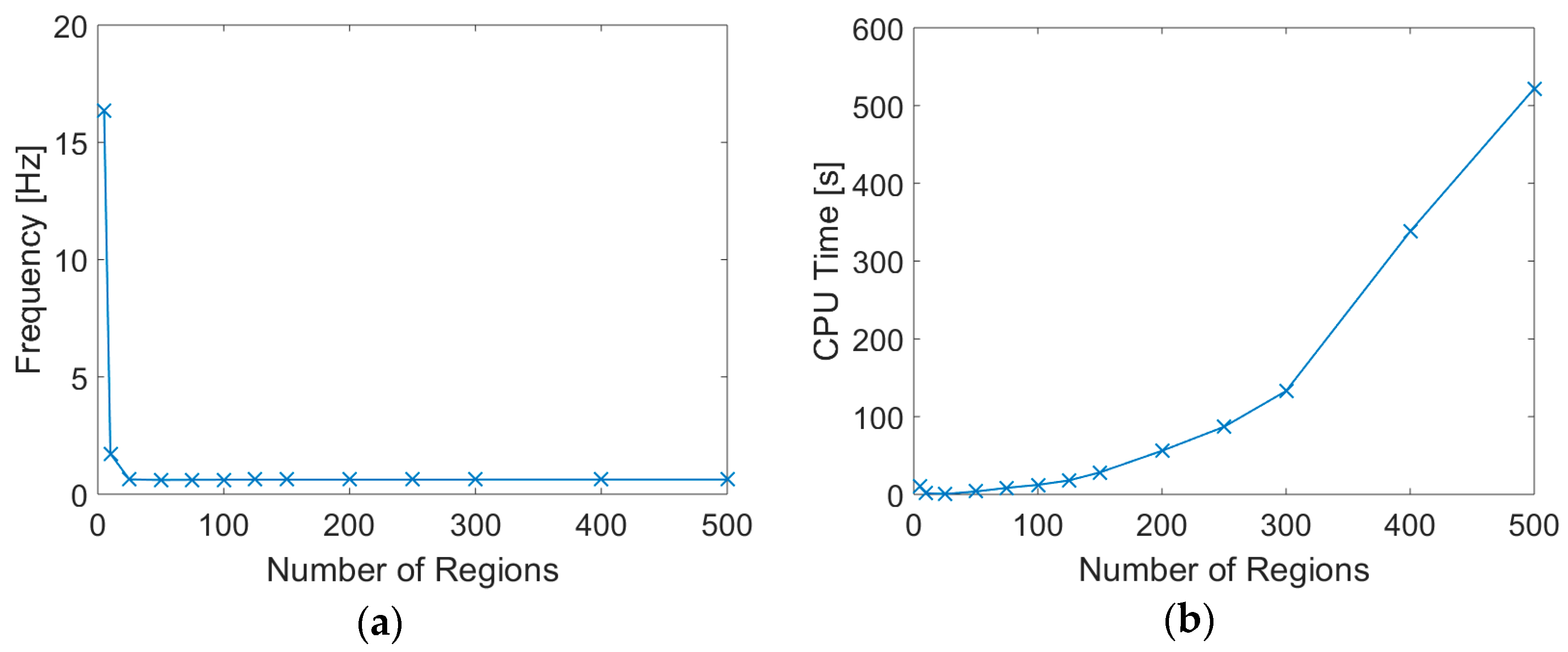
Figure 8 shows the effects of the number of regions that the beam is separated into for solution. Figure 8a shows that after 25 regions there is no significant change in the calculated first natural frequency of the beam. Figure 8b represents the CPU time elapsed to run the solution process. It should be noted that the computation was performed for the first 20 natural frequencies without using parallelisation and ran on a computer with an 8 GB RAM and Intel (Santa Clara, CA, United States) Core i7-6500U CPU @ 2.50 GHz (4 CPUs), ~2.6 GHz. It can be confidently claimed that after 100 regions, a significant rise in computational time was observed. Combining these two plots, it can be stated that 50 regions would be sufficient to achieve a satisfactory accuracy-computational time balance for this case. It is crucial to stress that the necessary number of regions will vary depending on the functions that represent the changing properties of the cross section and the material which the beam/blade is made of. The Abaqus (Dassault Systémes, Vélizy-Villacoublay, France) model requires 184 s to solve the first 20 modes of this blade structure on the same machine, and to keep a better comparison. The FE model was solved also without being in parallelisation.
4. Discussion
The error/deviation between the results of the two methods can be explained with the assumptions of the beam formulation, which includes the homogenisation of the material properties, averaging the cross-sectional properties throughout the regions along the beam axis and rigid motion of the cross section during deformation of the beam. More specifically, the reason that the analytical beam model has a slightly stiffer characteristic than the 3D FE model lies in the rigid cross-section assumption of the beam. It is claimed that during the deformation of the beam, the cross section of the beam preserves its initial shape, or in other words, it remains rigid and only undergoes rigid body motion, translation, and rotation. This leads to a stiffer behaviour than a real blade where the skin and the stiffening web make a thin-walled structure that can actually deform. However, the error introduced by this assumption does not cause the results to divert significantly from the numerical model, which is considered to be more realistic and computationally more expensive.
Apart from the natural frequencies, some coupled mode shapes are obtained. Here, the flexural (bending) and torsional modes are coupled. This occurs due to the formulation of the beam theory, which includes an asymmetrical cross section. Having an asymmetrical cross section causes the elastic, shear centres, centroid and centre of mass to be non-coincident. Particularly, the centre of mass is located further away from the rest due to both asymmetrical cross section and varying material properties throughout the cross section. This causes a twist during a bending motion or bending during torsional motion. Theoretically, all the bending and torsional modes are coupled. However, in all modes among the first eight (except for modes 6 and 8), one of the bending modes or the torsional mode is quite dominant. Therefore, these modes are named after the dominant mode character.
5. Conclusions
The main motivation of this study is to represent wind turbine blades with a more simplistic and analytical model. Hence, this study presented a novel beam formulation for three-dimensional free vibrations of beams made of axially FGM, with a varying and asymmetrical cross section. To validate the beam model, a 3D FE wind turbine model was used. The functions that define the cross-sectional and material properties of the blade were calculated using an open-source software, BECAS, which provided the necessary data from discrete points of the blade. The formulation evaluated the beam by dividing the beam into sections along the axis. Each region was handled with constant material and cross-sectional properties by calculating the average values for each quantity along the region. This allowed us to keep the model linear and easy to solve.
Comparing the results of both models, it can be stated that both are consistent and in good agreement. The error was spotted as approximately 2–3% for each mode where the maximum error was obtained as roughly 3%. Furthermore, the coupling of torsional and bending modes were observed in the mode shapes obtained from the FEM which occurred due to the asymmetrical cross-sectional geometry and nonhomogeneous material properties.
Author Contributions
Conceptualization, M.T., A.T. and E.T.; methodology, M.T. and E.T.; software, M.T. and Ö.E.G.; validation, M.T., Ö.E.G. and E.T.; formal analysis, M.T. and Ö.E.G.; investigation, M.T. and Ö.E.G.; resources, A.T.; data curation, M.T. and Ö.E.G.; writing—original draft preparation, M.T., Ö.E.G., A.T. and E.T.; writing—review and editing, M.T., Ö.E.G., A.T. and E.T.; visualization, Ö.E.G.; supervision, E.T.; project administration, E.T. and A.T. All authors have read and agreed to the published version of the manuscript.
Funding
This research received no external funding.
Conflicts of Interest
The authors declare no conflict of interest.
Appendix A
Appendix B
References
- Thomsen, O.T. Sandwich Materials for Wind Turbine Blades—Present and Future. J. Sandw. Struct. Mater. 2009, 11, 7–26. [Google Scholar] [CrossRef]
- Schubel, P.; Crossley, R.J. Wind Turbine Blade Design. Energies 2012, 5, 3425–3449. [Google Scholar] [CrossRef] [Green Version]
- Brøndsted, P.; Lilholt, H.; Lystrup, A. Composite materials for wind power turbine blades. Annu. Rev. Mater. Res. 2005, 35, 505–538. [Google Scholar] [CrossRef]
- Malek, S.; Raney, J.R.; A Lewis, J.; Gibson, L.J. Lightweight 3D cellular composites inspired by balsa. Bioinspir. Biomim. 2017, 12, 026014. [Google Scholar] [CrossRef] [PubMed]
- E Theotokoglou, E.; Balokas, G. Computational analysis and material selection in cross-section of a composite wind turbine blade. J. Reinf. Plast. Compos. 2014, 34, 101–115. [Google Scholar] [CrossRef]
- Kong, C.; Bang, J.; Sugiyama, Y. Structural investigation of composite wind turbine blade considering various load cases and fatigue life. Energy 2005, 30, 2101–2114. [Google Scholar] [CrossRef]
- Ozyildiz, M.; Muyan, C.; Coker, D. Strength Analysis of a Composite Turbine Blade Using Puck Failure Criteria. J. Phys. Conf. Ser. 2018, 1037, 042027. [Google Scholar] [CrossRef]
- Baumgart, A. A mathematical model for wind turbine blades. J. Sound Vib. 2002, 251, 1–12. [Google Scholar] [CrossRef]
- Bechly, M.; Clausen, P.D. Structural design of a composite wind turbine blade using finite element analysis. Comput. Struct. 1997, 63, 639–646. [Google Scholar] [CrossRef]
- Post, N.; Case, S.; Lesko, J. Modeling the variable amplitude fatigue of composite materials: A review and evaluation of the state of the art for spectrum loading. Int. J. Fatigue 2008, 30, 2064–2086. [Google Scholar] [CrossRef]
- Chang, L.; Yu, Y.; Liu, T. Aeroelastic Flutter and Sliding Mode Control of Wind Turbine Blade. Shock. Vib. 2020, 2020, 8846529. [Google Scholar] [CrossRef]
- Guo, S.; Li, Y.; Chen, W. Analysis on dynamic interaction between flexible bodies of large-sized wind turbine and its response to random wind loads. Renew. Energy 2020, 163, 123–137. [Google Scholar] [CrossRef]
- Bazilevs, Y.; Hsu, M.-C.; Kiendl, J.; Wüchner, R.; Bletzinger, K. 3D simulation of wind turbine rotors at full scale. Part II: Fluid-structure interaction modeling with composite blades. Int. J. Numer. Methods Fluids 2011, 65, 236–253. [Google Scholar] [CrossRef]
- Roul, R.; Kumar, A.; Roul, R. Fluid-Structure Interaction of Wind Turbine Blade Using Four Different Materials: Numerical Investigation. Symmetry 2020, 12, 1467. [Google Scholar] [CrossRef]
- Júnior, C.J.F.; Cardozo, A.C.P.; Júnior, V.M.; Neto, A.G. Modeling wind turbine blades by geometrically-exact beam and shell elements: A comparative approach. Eng. Struct. 2019, 180, 357–378. [Google Scholar] [CrossRef] [Green Version]
- Cardenas, D.; Escárpita, A.A.; Elizalde, H.; Aguirre, J.J.; Ahuett, H.; Marzocca, P.; Probst, O.; Ahuett-Garza, H. Numerical validation of a finite element thin-walled beam model of a composite wind turbine blade. Wind. Energy 2011, 15, 203–223. [Google Scholar] [CrossRef]
- Nabi, S.M.; Ganesan, N. Comparison of beam and plate theories for free vibrations of metal matrix composite pre-twisted blades. J. Sound Vib. 1996, 189, 149–160. [Google Scholar] [CrossRef]
- Kim, T.; Hansen, A.M.; Branner, K. Development of an anisotropic beam finite element for composite wind turbine blades in multibody system. Renew. Energy 2013, 59, 172–183. [Google Scholar] [CrossRef] [Green Version]
- Kosmatka, J.B.; Friedmann, P.P. Vibration analysis of composite turbopropellers using a nonlinear beam-type finite-element approach. AIAA J. 1989, 27, 1606–1614. [Google Scholar] [CrossRef]
- Vo, T.; Thai, H.-T.; Aydogdu, M. Free vibration of axially loaded composite beams using a four-unknown shear and normal deformation theory. Compos. Struct. 2017, 178, 406–414. [Google Scholar] [CrossRef]
- Kunz, D.L. Survey and comparison of engineering beam theories for helicopter rotor blades. J. Aircr. 1994, 31, 473–479. [Google Scholar] [CrossRef]
- Hodges, D.H. Review of composite rotor blade modeling. AIAA J. 1990, 28, 561–565. [Google Scholar] [CrossRef]
- Eipakchi, H.; Sohani, F. Analytical solution for modal analysis of Euler-Bernoulli and Timoshenko beam with an arbitrary varying cross-section. Math. Model. Eng. 2018, 4, 164–174. [Google Scholar] [CrossRef]
- Barr, S.M.; Jaworski, J.W. Optimization of tow-steered composite wind turbine blades for static aeroelastic performance. Renew. Energy 2019, 139, 859–872. [Google Scholar] [CrossRef]
- Capuzzi, M.; Pirrera, A.; Weaver, P.M. Structural design of a novel aeroelastically tailored wind turbine blade. Thin-Walled Struct. 2015, 95, 7–15. [Google Scholar] [CrossRef] [Green Version]
- Patni, M.; Minera, S.; Groh, R.M.J.; Pirrera, A.; Weaver, P.M. On the accuracy of localised 3D stress fields in tow-steered laminated composite structures. Compos. Struct. 2019, 225, 111034. [Google Scholar] [CrossRef]
- Yucel, A.; Arpaci, A.; Tüfekci, E. Coupled axial-flexural-torsional vibration of Timoshenko frames. J. Vib. Control. 2013, 20, 2366–2377. [Google Scholar] [CrossRef]
- Otero, A.D.; Ponta, F.L. Structural Analysis of Wind-Turbine Blades by a Generalized Timoshenko Beam Model. J. Sol. Energy Eng. 2010, 132, 011015. [Google Scholar] [CrossRef]
- Malcolm, D.J.; Laird, D.L. Modeling of Blades as Equivalent Beams for Aeroelastic Analysis. ASME 2003 Wind Energy Symp. 2003, 2003, 293–303. [Google Scholar] [CrossRef] [Green Version]
- Sayyad, A.S.; Ghugal, Y.M. Bending, buckling and free vibration of laminated composite and sandwich beams: A critical review of literature. Compos. Struct. 2017, 171, 486–504. [Google Scholar] [CrossRef]
- Hajianmaleki, M.; Qatu, M.S. Vibrations of straight and curved composite beams: A review. Compos. Struct. 2013, 100, 218–232. [Google Scholar] [CrossRef]
- Kant, T.; Marur, S.R.; Rao, G. Analytical solution to the dynamic analysis of laminated beams using higher order refined theory. Compos. Struct. 1997, 40, 1–9. [Google Scholar] [CrossRef]
- Savoia, M.; Tullini, N. Beam theory for strongly orthotropic materials. Int. J. Solids Struct. 1996, 33, 2459–2484. [Google Scholar] [CrossRef]
- Nath, S.K.D. A Finite Difference Solution of a Simply Supported Beam of Orthotropic Composite Materials Using Displacement Potential Formulation. Chin. J. Eng. 2014, 2014, 1–11. [Google Scholar] [CrossRef] [Green Version]
- Zhou, Z.; Chen, M.; Xie, K. NURBS-based free vibration analysis of axially functionally graded tapered Timoshenko curved beams. Appl. Math. Mech. 2020, 41, 1–20. [Google Scholar] [CrossRef]
- Eroglu, U. Large deflection analysis of planar curved beams made of Functionally Graded Materials using Variational Iterational Method. Compos. Struct. 2016, 136, 204–216. [Google Scholar] [CrossRef]
- Tufekci, E.; Eroglu, U.; Aya, S.A. Exact solution for in-plane static problems of circular beams made of functionally graded materials. Mech. Based Des. Struct. Mach. 2016, 44, 476–494. [Google Scholar] [CrossRef]
- Hadji, L.; Khelifa, Z.; El Abbes, A.B. A new higher order shear deformation model for functionally graded beams. KSCE J. Civ. Eng. 2015, 20, 1835–1841. [Google Scholar] [CrossRef]
- Eroglu, U.; Tüfekci, E. Small-Amplitude free vibrations of straight beams subjected to large displacements and rotation. Appl. Math. Model. 2018, 53, 223–241. [Google Scholar] [CrossRef]
- Bagheri, S.; Nikkar, A.; Ghaffarzadeh, H. Study of nonlinear vibration of Euler-Bernoulli beams by using analytical approximate techniques. Lat. Am. J. Solids Struct. 2014, 11, 157–168. [Google Scholar] [CrossRef] [Green Version]
- Bauchau, O.A.; Hong, C.H. Nonlinear Composite Beam Theory. J. Appl. Mech. 1988, 55, 156–163. [Google Scholar] [CrossRef] [Green Version]
- Foraboschi, P. Analytical Solution of Two-Layer Beam Taking into Account Nonlinear Interlayer Slip. J. Eng. Mech. 2009, 135, 1129–1146. [Google Scholar] [CrossRef]
- Monetto, I. Analytical solutions of three-layer beams with interlayer slip and step-wise linear interface law. Compos. Struct. 2015, 120, 543–551. [Google Scholar] [CrossRef]
- Eroglu, U.; Tüfekci, E. Some closed-form solutions for buckling of straight beams with varying cross-section by Variational Iteration Method with Generalized Lagrange Multipliers. Int. J. Eng. Appl. Sci. 2018, 10, 159–175. [Google Scholar] [CrossRef]
- Banerjee, J.R.; Williams, F.W. Coupled Bending-Torsional Dynamic Stiffness Matrix of an Axially Loaded Timoshenko Beam Element. Int. J. Solids Struct. 1994, 31, 749–762. [Google Scholar] [CrossRef]
- Freund, J.; Karakoç, A. Warping displacement of Timoshenko beam model. Int. J. Solids Struct. 2016, 92, 9–16. [Google Scholar] [CrossRef]
- Freund, J.; Karakoç, A. Shear and torsion correction factors of Timoshenko beam model for generic cross sections. Res. Eng. Struct. Mater. 2016, 2. [Google Scholar] [CrossRef]
- Malcolm, D.J.; Laird, D.L. Extraction of equivalent beam properties from blade models. Wind. Energy 2007, 10, 135–157. [Google Scholar] [CrossRef]
- Hodges, D.H.; Yu, W. A rigorous, engineer-friendly approach for modelling realistic, composite rotor blades. Wind. Energy 2007, 10, 179–193. [Google Scholar] [CrossRef]
- Yu, W.; Blair, M. GEBT: A general-purpose nonlinear analysis tool for composite beams. Compos. Struct. 2012, 94, 2677–2689. [Google Scholar] [CrossRef]
- Cesnik, C.E.S.; Hodges, D.H. VABS: A New Concept for Composite Rotor Blade Cross-Sectional Modeling. J. Am. Helicopter Soc. 1997, 42, 27–38. [Google Scholar] [CrossRef]
- Blasques, J.P.A.A.; Stolpe, M. Multi-material topology optimization of laminated composite beam cross sections. Compos. Struct. 2012, 94, 3278–3289. [Google Scholar] [CrossRef] [Green Version]
- Eaton, J.W.; Bateman, D.; Hauberg, S.; Wehbring, R. GNU Octave Version 5.2.0 Manual: A High-Level Interactive Language for Numerical Computations. 2019. Available online: https://www.gnu.org/software/octave/doc/v5.2.0/ (accessed on 23 December 2020).
- Bak, C.; Zahle, F.; Bitsche, R.; Kim, T.; Yde, A.; Henriksen, L.C.; Hansen, M.H.; Blasques, J.P.A.A.; Gaunaa, M.; Natarajan, A. The DTU 10-MW Reference Wind Turbine; Sound/Visual Production (Digital); DTU Library: Copenhagen, Denmark, 2013; Available online: https://orbit.dtu.dk/en/publications/the-dtu-10-mw-reference-wind-turbine (accessed on 23 December 2020).
Figure 1.
DTU-10MW-RWT blade [54].
Figure 1.
DTU-10MW-RWT blade [54].
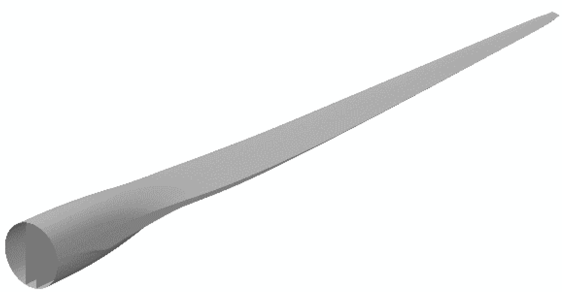
Figure 2.
The coordinate system used in the formulation.

Figure 3.
Geometry and mesh structure of the composite blade.

Figure 4.
The variations of area and area moment of inertia properties of the blade.

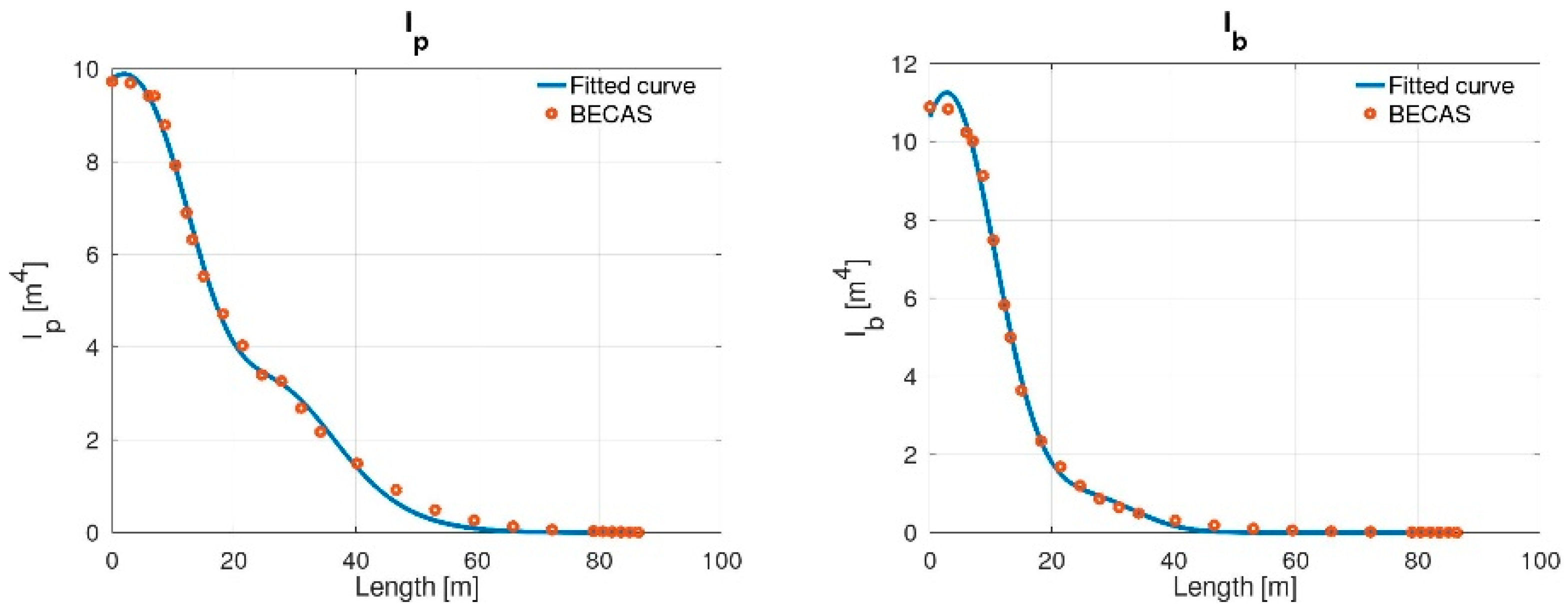
Figure 5.
The variations of shear correction factors and coordinates of centre of mass (CM) and shear centre (SC) of the blade.
Figure 5.
The variations of shear correction factors and coordinates of centre of mass (CM) and shear centre (SC) of the blade.
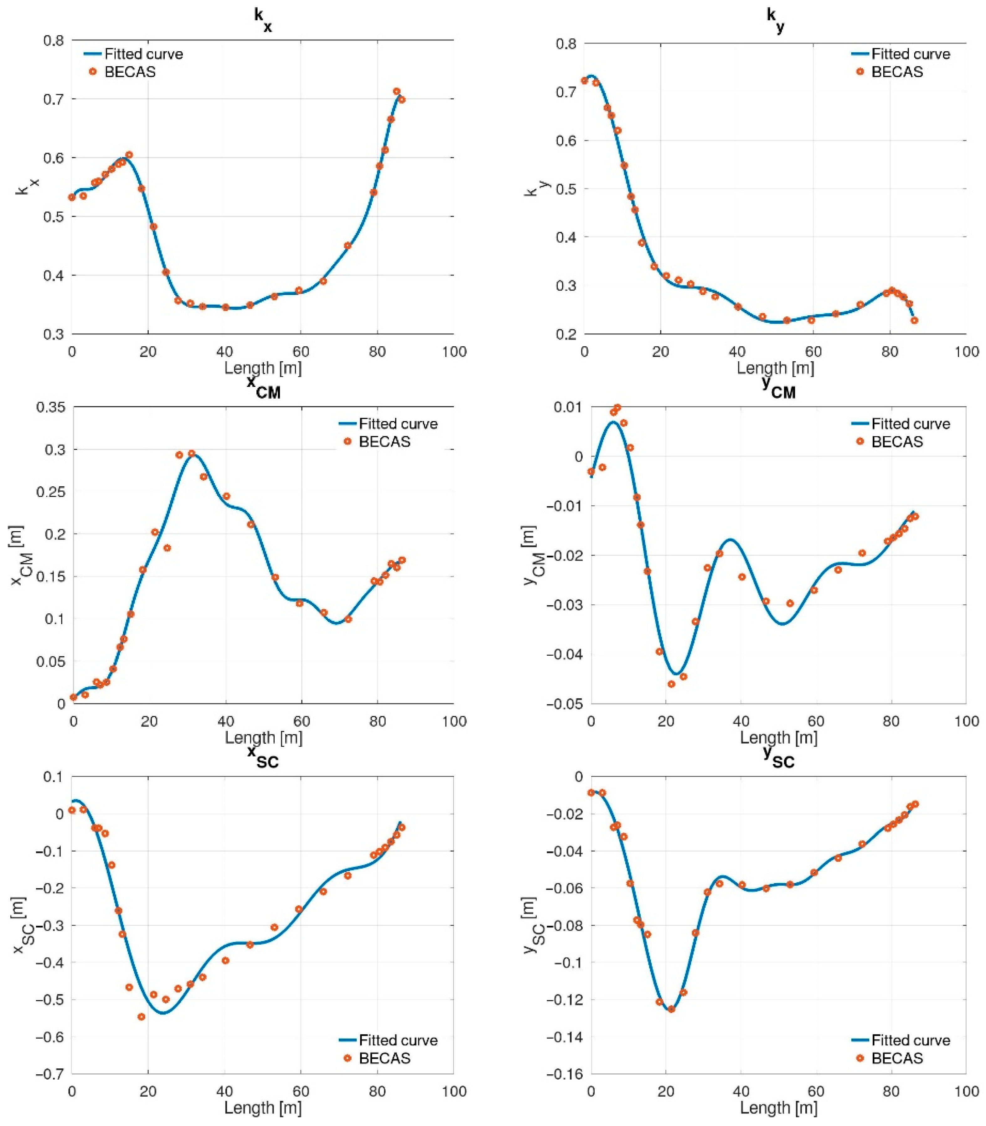
Figure 6.
The variations of material properties of the blade.

Figure 7.
Finite element mode shapes of the DTU-10MW-RWT blade.

Figure 8.
Dependence on the number of regions on the beam: (a) the first natural frequency (b) elapsed CPU time.
Figure 8.
Dependence on the number of regions on the beam: (a) the first natural frequency (b) elapsed CPU time.


Table 1.
Vibration modes of DTU-10MW-RWT blade.
| Mode | Analytical Nat. Frequency [Hz] | FEM Nat. Frequency [Hz] | Mode Type | Error [%] |
|---|---|---|---|---|
| 1 | 0.63 | 0.61 | Flapwise bending | 3.17 |
| 2 | 0.98 | 0.95 | Edgewise bending | 3.06 |
| 3 | 1.76 | 1.76 | Flapwise bending | 0 |
| 4 | 2.88 | 2.84 | Edgewise bending | 1.39 |
| 5 | 3.66 | 3.60 | Flapwise bending | 1.64 |
| 6 | 5.81 | 5.70 | Coupled flapwise-edgewise bending | 1.89 |
| 7 | 5.89 | 5.73 | Torsional | 2.72 |
| 8 | 6.28 | 6.13 | Coupled flapwise-edgewise bending | 2.39 |
Publisher’s Note: MDPI stays neutral with regard to jurisdictional claims in published maps and institutional affiliations. |
© 2020 by the authors. Licensee MDPI, Basel, Switzerland. This article is an open access article distributed under the terms and conditions of the Creative Commons Attribution (CC BY) license (http://creativecommons.org/licenses/by/4.0/).
Share and Cite
MDPI and ACS Style
Tüfekci, M.; Genel, Ö.E.; Tatar, A.; Tüfekci, E. Dynamic Analysis of Composite Wind Turbine Blades as Beams: An Analytical and Numerical Study. Vibration 2021, 4, 1-15. https://0-doi-org.brum.beds.ac.uk/10.3390/vibration4010001
AMA Style
Tüfekci M, Genel ÖE, Tatar A, Tüfekci E. Dynamic Analysis of Composite Wind Turbine Blades as Beams: An Analytical and Numerical Study. Vibration. 2021; 4(1):1-15. https://0-doi-org.brum.beds.ac.uk/10.3390/vibration4010001
Chicago/Turabian StyleTüfekci, Mertol, Ömer Ekim Genel, Ali Tatar, and Ekrem Tüfekci. 2021. "Dynamic Analysis of Composite Wind Turbine Blades as Beams: An Analytical and Numerical Study" Vibration 4, no. 1: 1-15. https://0-doi-org.brum.beds.ac.uk/10.3390/vibration4010001