
Effect of Impeller Diameter on Dynamic Response of a Centrifugal Pump Rotor


1
Department of Mechanical Engineering, Bu-Ali Sina University, Hamedan 65175-4161, Iran
2
Automotive Engineering Department, Tehran 16846-13114, Iran
*
Author to whom correspondence should be addressed.
Vibration 2021, 4(1), 117-129; https://0-doi-org.brum.beds.ac.uk/10.3390/vibration4010010
Submission received: 26 November 2020
/
Revised: 11 January 2021
/
Accepted: 26 January 2021
/
Published: 9 February 2021
(This article belongs to the Special Issue Inverse Dynamics Problems)
Abstract
:This paper investigates the effect of impeller diameter on the dynamic response of a centrifugal pump using an inverse dynamic method. For this purpose, the equations of motion of the shaft and the impeller are derived based on Timoshenko beam theory considering the impeller as a concentrated mass disk. For practical modeling, the model of Jones and Harris is added to the equation to include the effect of bearings. As a case study, the model is applied to a process pump used in an oil refinery. Computing the eigenvalues of the model and comparing them with the natural frequencies of the structure, the model updating of the problem is performed through an indirect method. Three impellers with different diameters are applied to the updated model. The results show that increasing the diameter of the pump impeller can increase the amplitude of vibration up to 52% at critical speeds of the rotor. It is found that in addition to the hydraulic condition and efficiency, the impeller diameter should be considered as an important factor in the selection of centrifugal pumps.
1. Introduction
Rotating machineries such as pumps, compressors, turbines, etc., play an important role in many different industries. Accurate predictions of rotor system dynamic characteristics are very important in the design of any type of machines. There have been many studies relating to the field of rotor dynamic systems during the recent years. Engineers have developed several new techniques about the dynamics of rotating machines.
The first recorded theory of rotor dynamics was in a classic paper of Jeffcott [1]. The Jeffcott rotor model has been used to explain the whirling effect. It consists of a simply supported flexible massless shaft with a rigid disc mounted at the mid-span. In the Jeffcott model, the moments of inertia and are not considered. This is because there are no gyroscopic moments exerted on the shaft. The disc is assumed to move in a plane that is perpendicular to the shaft spin axis. By developments in the technology of rotating machines, the rotational speed of rotors became higher, and so, the non-conservative forces generated through the bearings of the rotor become considerable. To determine the critical speeds in which resonance has occurred, it is necessary to know the natural frequencies, mode shapes, and forced responses, which are caused by unbalancing in rotor systems. Prohl studied the critical speed evaluation of a turbine shaft, and he suggested the transfer matrix method [2]. The first application of the finite element method for a rotor system was made by Ruhl and Booker [3]. In their study, the influences of the rotary inertia, gyroscopic moment, bending, shear deformation, axial load, and internal damping were neglected to simplify the model. The theory has been developed by considering the rotary inertia, gyroscopic moment, and axial forces. Nelson and McVaugh extended this to include gyroscopic effects. They derived the equations of motion for the shaft and the effects of translational and rotary inertia and gyroscopic moments on it [4]. Erturka et al. presented an analytical method based on Timoshenko beam theory for calculating the frequency response function (FRF) of a spindle–holder–tool combination. They proposed a mathematical model and obtained the point FRF for a tool [5]. Subbiah et al. showed that a rotor has certain speed ranges in which a large amplitude of vibration could occur. These speed ranges are known as critical speed, which results in excessive rotor deflection [6]. Phadatare and Barun described a step forward in calculating the nonlinear frequencies and resultant dynamic behavior of a high-speed rotor bearing system with unbalanced mass. In this study, Fast Fourier Transform (FFT) analysis was established for finding the fundamental frequencies of the rotor according to the variation of shaft diameter and location of unbalanced mass [7]. Metsebo et al. have focused on the influence of the rotating shaft on the dynamic of a rotor ball bearing system. They carried out a mathematical modeling for the system considering the shaft as a Timoshenko beam [8].
Ball bearings are the essential elements of rotating machineries. So, the influence of bearings on the performance of rotor-bearing systems is very important. El-Sayed derived a set of equations for the stiffness of bearings using the Hertz theory and determined the total deflections of inner and outer races caused by an applied load [9]. Tamura and Tsuda performed a theoretical study about fluctuations of radial spring characteristics of a ball bearing due to ball revolutions [10]. Many researchers also estimated bearing stiffness by carrying out some experiments. Stone and Walford developed a rotor-bearing test rig to estimate the bearing’s radial stiffness and damping by measuring the response of the rotor [11]. Jairo et al. presented an experimental validation for a mathematical modeling of ball bearing. In this model, the bearing was considered as a mass-spring-damper system based on Hertz equations for contact deformation [12]. Xia sheng et al. proposed a mathematical model for the stiffness of bearings, which is varying by speed. They explained that the speed of a rolling bearing varies the stiffness of the bearing [13]. Zhang et al. investigated the effect of ring misalignment on the service characteristics of ball bearing and rotor systems [14]. They improved a quasi-static model of ball bearing considering the misalignment in its ring. Neisi et al. worked on the effect of off-sized balls on contact stresses in a touchdown bearing [15]. Yi Qin et al. developed a dynamics model for deep groove ball bearings with local faults based on coupled and segmented displacement excitation [16]. Chandrasekaran et al. used computational fluid dynamic (CFD) methods and mathematical modeling to investigate the impeller design parameters on the effect of fluid follows in the centrifugal pumps [17].
The objective of this paper is investigation on the effect of impeller diameter on the amplitude of vibration at critical speeds in an overhung centrifugal pump. Modeling of the shaft and impeller is based on Timoshenko theory, and modeling of the bearing is based on the work of Jones and Harris, which is added to the model of shaft simultaneously. Then, numerical analysis for a real centrifugal pomp in the oil refinery has been done based on the proposed model. It has shown that in addition of the effect of the geometrical parameter of the shaft, the effect of the diameter of the impeller on the dynamical behavior of the pump is very important.
The novelty of this research is the development of the mathematical model of the shaft, impeller, and bearing simultaneously. Using this developed model, the effect of impeller size diameter on the dynamic behavior of a centrifugal pump has been investigated, and it has been shown that it is very considerable.
This paper includes four sections. In the first section, the literature has been reviewed and the necessity of research has been recognized. In the second section, the model of the system has been introduced and the equation of motion based on the energy method has been derived by calculating the potential and kinetic energy of the system. In the third section, the model of the bearing has been presented, and the governing equations of motion for the ball bearing have been introduced. Finally, in the last section, the derived equations have been used and solved.
For an actual centrifugal pump, the effect of impeller diameter on the amplitude of vibration has been investigated.
2. System Modeling
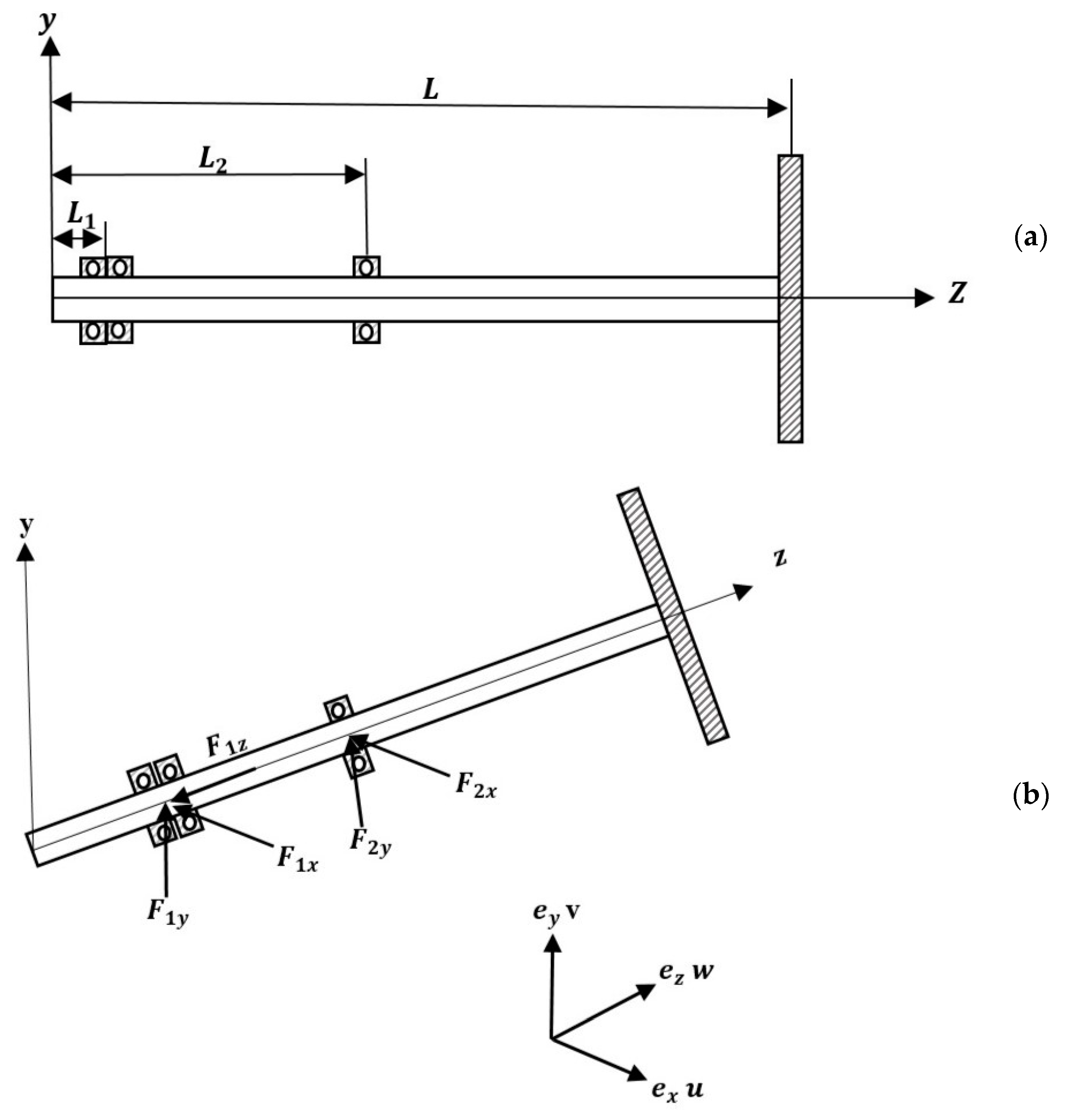
The rotor of a centrifugal pump is approximated by a simple model as shown in Figure 1a. The model is composed of a shaft of length L and supported by two bearings located at and along the shaft. u, v, and w reflect the displacement in the , , and directions, respectively.
The shaft is modeled as a Timoshenko beam. In this model, first-order shear deformation theory with rotary inertia and gyroscopic effect has been considered. The shaft rotates at a constant speed around its longitudinal axis. In addition, it has a uniform, circular cross-section.
The equations of motion of the system are obtained using the Lagrangian equations as:
where T is the total kinetic energy of the system, U is the total potential energy of the system, qn is the generalized coordinate and Qnc represents non-conservative forces that are not directly related to the potential energy of the system. So, to derive the governing equations of motion using Equation (1), one must calculate the kinetic and potential energy of the system.
The total kinetic energy of a rotor system is estimated by the dynamic motion of the shaft and disk [14].
The kinetic energy due to the rotation of the disk is difficult to calculate. Therefore, we assume that the disk is symmetric and rigid and has been fixed at the end of the shaft. The motion of the disk can be defined as two superimposed rotations , and two translational deflections u, v in directions , . So, the kinetic energy of the disk can be expressed as:
where M is the mass of the rigid disk, is the diametral mass moment of inertia, and is the polar mass moment of inertia. The term represents the gyroscopic effect, and finally, the last term defines the kinetic energy due to the rotation of the disk.
The kinetic energy of the shaft involves the kinetic energy due to bending of the shaft, effect of rotatory inertia, and gyroscopic effect. The kinetic energy of the shaft can be derived as:
where A is the cross-sectional area, is the density of the shaft, and and are the diametric and polar inertia of the shaft, respectively. So, substituting Equations (3) and (4) in Equation (2), the total kinetic energy of system has been obtained.
The potential energy of the system includes the strain energy due to the deformation of the shaft () and the strain potential energy due to the deflection of the bearing installed on the shaft () [12]:
The strain energy of the shaft can be expressed as:
where E represents the modulus of elasticity, G is the shear modulus, and k is the shear coefficient. In addition, A and I are the cross-section area and moment of inertia of the shaft receptivity. In the above equation, the first term is related to the shaft bending, and the second term is due to shear deformation. In addition, the potential energy caused by bearing forces can be expressed as:
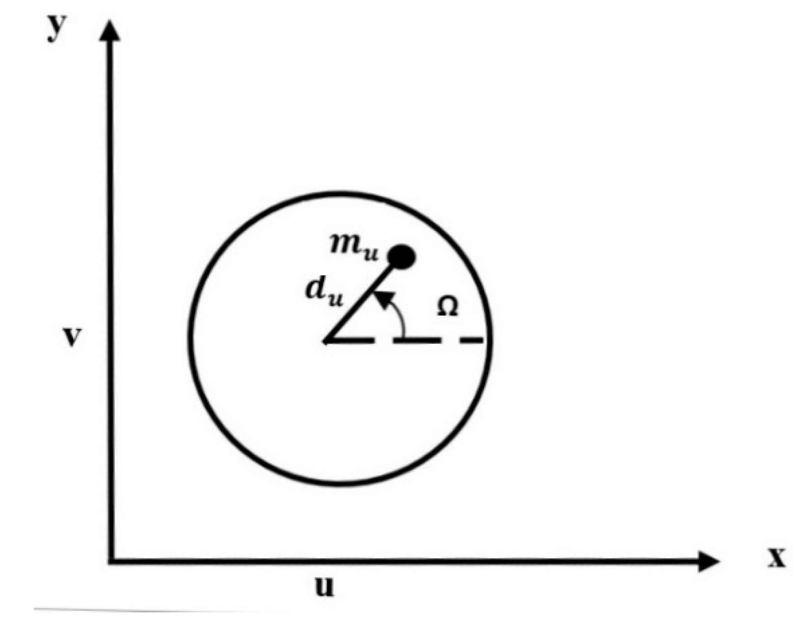
Different forces work on the impeller as a consequence of the fluid. These forces are non-conservative forces and are unknown, and they have been ignored for simplicity. However, mass unbalance generates an additional centrifugal force that makes it possible to calculate this non-conservative force. If the impeller is out of balance, the resulting centrifugal force will induce the rotor to vibrate. When the shaft rotates at a speed equal to the natural frequency, this vibration becomes large. Unbalance is defined by a small mass situated at a distance from the geometric center of the impeller, as shown in Figure 2 [13].
The out of balance force at the end of the rotor is:
This rotating force can be resolved into two components in the x and y direction as:
It is assumed that the unbalance mass is in the x direction in the initial state. The deflections in the x and y directions are expressed as:
where and are generalized independent coordinates and f(z) is the displacement function that satisfies the boundary conditions of the system. As the rotor of the centrifugal pump has simply supported at both ends, f(z) has been selected as [12]:
The angular displacements and are assumed to be small. So, they are approximated by the derivative of u and v with respect to the z-direction. Therefore, using Equations (10) and (11), and have been expressed as:
To derive the equations of motion, the kinetic energy and the potential energy are specified by generalized coordinates. So, using Equation (3), the kinetic energy of the disk in generalized coordinates is expressed as:
where
In addition, Equation (4) in the generalized equation becomes:
Likewise, using the generalized coordinates, the potential energy in the generalized coordinate will be:
where represnts the dirac delta function and
In addition, substituting the displacement function into the kinetic energy of the mass unbalance expression of Equation (11) gives:
Ball Bearing Model
In this section, a mathematical model for calculating bearing stiffness is proposed by analyzing the equations in the bearing dynamic model, which is based on Jones and Harris’s efforts [14]. This mathematical model aims to give a comprehensive consideration of the nonlinear stiffness of the ball bearing, and it can be seen that the bearing stiffness is critically dependent on the preloading, g, of the rolling elements. In case of rolling element bearings, the elastic deformation takes place at both the inner raceway and the outer raceway with the rolling element. Based on the Hertzian contact theory, the relation between load F and deflection is [15]:
where is the contact deformation and is a load–deformation constant for a single point contact (either at the inner or outer raceway). If the ball and raceway are made of steel, then [16,17]:
where is the dimensionless contact deformation and is the curvature sum [14]. So, one can write the stiffness of the inner and outer ring contact as:
where
and
In the above equations, subscripts i and o represent inner and outer raceways and is the ball diameter. In addition, is the pitch diameter, and are the inner and outer ring raceway contact diameter, and and are the inner and outer raceway groove radius, respectively.
The total deformation, , at a single rolling element location is given by:
Equation (19) can be rewritten as:
where
is the load–deformation constant for two point contacts of a ball with raceways.
To calculate the deformations, the conventions shown in Figure 3 are used. Considering the presence of radial clearance, the force produced by every spring in the horizontal and vertical direction can be obtained [18]:
where is the radial preload between the ball and races, u and v are the displacements of the moving ring in the x and y directions, respectively, and is the angular position of the i th element.
Finally, the bearing stiffness can be simplified to [15]:
where Z is the number of rolling elements.
It can be seen that the bearing stiffness is critically dependent on value of the preloading g of the rolling elements.
3. Numerical Solution
The model is applied for an installed pump (P-502B) in a Kermanshah oil refinery in Iran. This centrifugal pump and its impeller are shown in Figure 4.
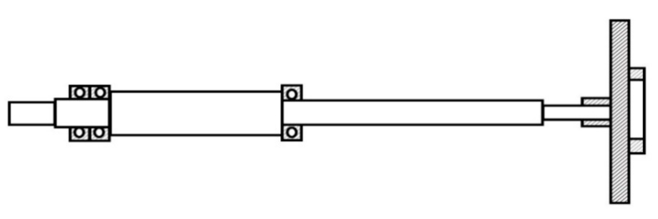
The schematic of the shaft and impeller of the above pump is shown in Figure 5. The flowing fluid is light petroleum gases including propane and butane.
The shaft of the mentioned pump is supported by two bearings SKF7308 and SKF6307, which have been installed in distance and respectively, see Figure 1a. In addition, three impellers with different diameters have been installed at the end of the shaft.
Bearing Stiffness of P-502B
To obtain the stiffness of the bearing, knowledge of the properties is necessary. The general properties of these ball bearings are shown in Table 3.
It can be seen that the bearing stiffness is critically dependent on the value of preloading force for the rolling elements.
Substituting the above values in Equation (25), the values of stiffness in the x and y directions have been obtained as:
Bearing stiffness for SKF6307:
Bearing stiffness for SKF7308:
Finally, using the Equations (3), (4), (6), (7) and Lagrangian Equation (1), the mathematical equation for the case study can be expressed as:
The above equation is a lumped parameter model that can be described as:
Looking at Equation (28), one can see that the damping matrix is dependent on the angular velocity of the shaft. The stiffness matrix is implicitly dependent on the amount of amplitude of vibration and so, the equations of motion are nonlinear equations. This will lead to a complicated model. So, for simplicity, normal clearance has been considered to make the value of the stiffness coefficient independent from the deflection, and so, the equations of motion will become linear ordinary differential equations. According to the SKF General catalog, hence and used for SKF6307 and SKF7308 respectively, the equivalent stiffness for bearings in a normal clearance case have been derived as follows:
To obtain the critical speed of the rotor, the eigenvalues and thus the natural frequencies of the system must be determined. To do this, a slightly different but equivalent approach can be used to combine the pair in Equation (29). By letting and subtracting j× in the second Equation (29) from the first Equation (29), we have [19]:
Now, we can solve this equation by letting and taking the positive root to obtain backward critical speed. If we let in which is the forward critical speed, one must add the out of balance moments to the system to determine the response. Thus:
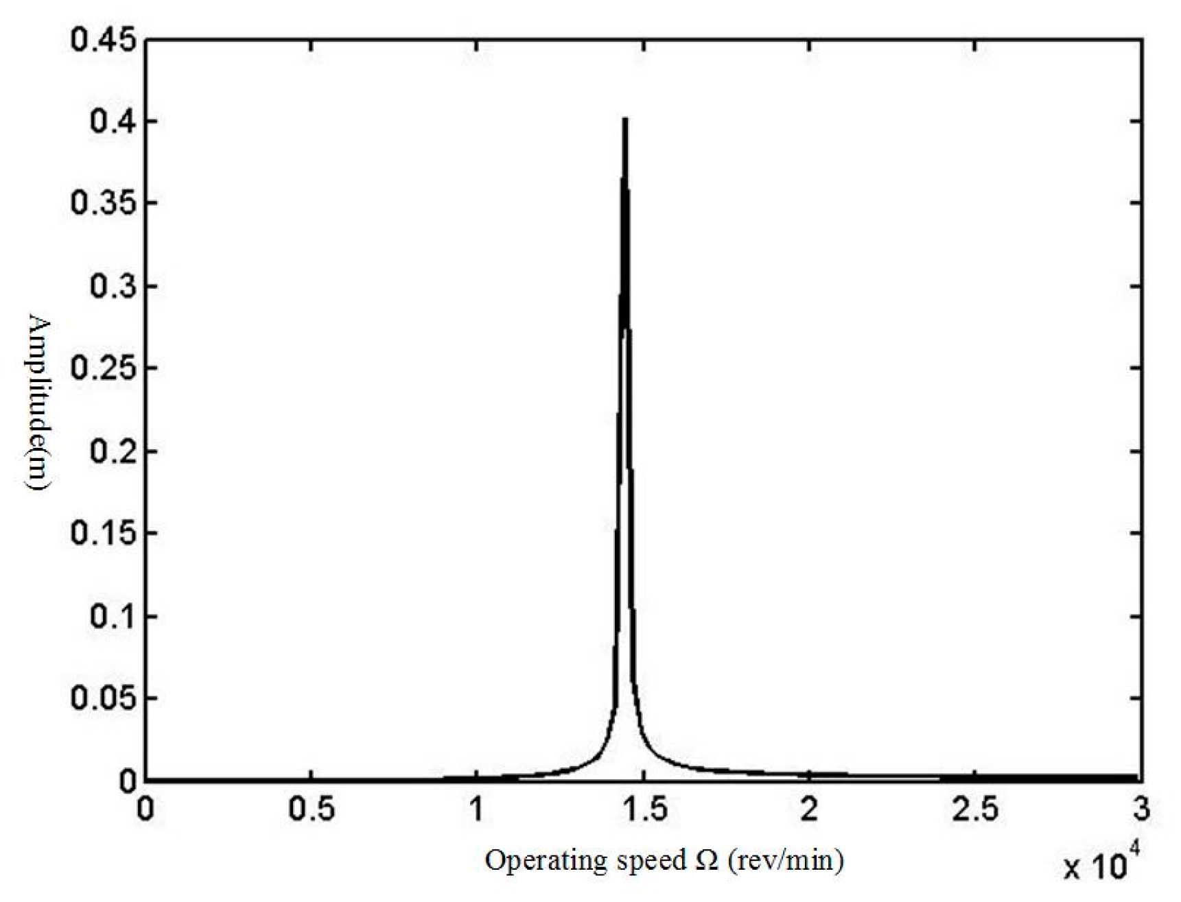
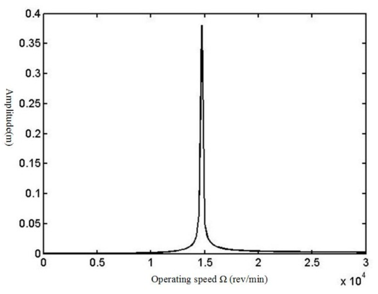
Likewise, by and subtracting j× in the second equation from the first, the rotor amplitude is calculated [19]. In addition, to determine the effect of impeller diameter, the various values of this parameter have been considered. To do this procedure, a code in MATLAB software has been written, and the following outputs shown in Figure 6, Figure 7 and Figure 8 have been derived.
The amplitudes of the rotor response plots for all pump impellers that are recommended by pump manufacture are shown in Figure 6, Figure 7 and Figure 8. The summary of the results is shown in Table 4.
So, one can see that by increasing the impeller diameter, the amplitude of vibration at critical speed will be increased up to 52%, while the value of critical speed will decrease. The value of amplitude of vibration shown in this table has been obtained without considering the structural damping of the shaft, bearings, and impeller and also the effects of fluid flow in the pump. So, in reality, these values are much smaller than the tabulated values in Table 4.
4. Conclusions
In this paper, the equations of motion for the shaft of a centrifugal pump have been derived using Lagrangian equations and based on Timoshenko beam theory and Jones and Harris [20,21] modeling for bearings based on Hertzian theory for rolling element [22,23]. By these equations, it is possible to define a lumped parameter model for the system and determine the amplitude of rotor in critical speeds [12,24]. The solutions of these equations for an applied case study show that as the impeller diameter increases, the amplitude of vibration at critical speeds increases, too. In this case study, by replacing the impeller diameter in the equations with a larger size (impeller diameter 0.256 m replaced with 0.32 m), it is shown that the amplitude is approximately increased by 52% in the critical speed. So, as the impeller trimming or impeller exchange is a general method for the maintenance in plants, it must be considered that the bigger diameter will yield more amplitude of vibration at critical speed.
It must be considered that modeling of the shaft, bearings, and impellers with details and assembling them and then conducting finite element analysis is very complex, and as the case study is a process pump in an oil refinery that works 24 h a day, stopping the production line and then measuring, modeling, and conducting FEM analysis is very expensive. On the other hand, the purpose of this manuscript is to introduce an analytical model for all the essential rotary parts of a centrifugal pump in detail and then conduct a sensitive analysis for the effect of impeller diameter on the critical speed of it inversely. For this purpose, the dynamic inverse solution is very suitable when there are practical limitations for FEM analysis, such as it being very complex and expensive.
Author Contributions
Investigation, A.S., M.K. and M.S.; Methodology, A.S. and S.S. All authors have read and agreed to the published version of the manuscript.
Funding
This research received no external funding.
Institutional Review Board Statement
Not applicable.
Informed Consent Statement
Not applicable.
Data Availability Statement
Not applicable.
Conflicts of Interest
The authors declare no conflict of interest.
References
- Jeffcott, H.H. The lateral vibration of loaded shafts in neighborhood of a whirling speed: The effect of want of balance. Philos. Mag. 1919, 6, 304–314. [Google Scholar] [CrossRef] [Green Version]
- Prohl, M.A. A general method for calculating the critical speeds of flexible rotors. J. Appl. Mech. 1945, 12, 142–148. [Google Scholar]
- Ruhl, R.L.; Booker, J.F. A finite element model for distributed parameter turbo generator system. J. Eng. Ind. 1972, 94, 126–132. [Google Scholar] [CrossRef]
- Nelson, H.D.; McVaugh, J.M. The dynamics of rotor-bearing systems using finite elements. J. Eng. Ind. May 1976, 98, 593–600. [Google Scholar] [CrossRef]
- Erturk, A.; Ozguven, H.N.; Budak, E. Analytical modeling of spindle–tool dynamics on machine tools using Timoshenko beam model and receptance coupling for the prediction of tool point FRF. Int. J. Mach. Tools Manuf. 2006, 46, 1901–1912. [Google Scholar] [CrossRef]
- Subbiah, R.; Rieger, N. On the transient analysis of rotor bearing system. J. Vib. Acoust. Stress Reliab. Des. 1988, 110, 515–520. [Google Scholar] [CrossRef]
- Phadatare, H.P.; Pratiher, B. Nonlinear Frequencies and Unbalanced Response Analysis of High Speed Rotor-Bearing Systems. In Proceedings of the International Conference on Vibration Problems, Warangal, India, 18–20 February 2015. [Google Scholar]
- Metsebo, J.; Upadhgay, N.; Kankar, P.K.; Nbendjo, B.R.N. Modeling of a rotor-ball bearing system using timoshenko beam and effect of rotating shaft on their dynamics. J. Mech. Sci. Technol. 2016, 30, 5339–5350. [Google Scholar] [CrossRef]
- El-Sayed, H.R. Stiffness of deep-groove ball bearings. Wear 1980, 63, 89–94. [Google Scholar] [CrossRef]
- Tamura, H.; Tsuda, Y. On the spring characteristics of ball bearing. Bull. JSME 1980, 23, 961–969. [Google Scholar] [CrossRef]
- Stone, B.J.; Walford, T. The measurement of the radial stiffness of rolling element bearings under oscillating conditions. J. Mech. Eng. Sci. 1980, 22, 175–181. [Google Scholar]
- Grajales, J.A.; Lopez, J.F.; Quintero, H.F. Ball bearing vibration model: Development and experimental validation. J. Ing. Compet. 2014, 16, 279–288. [Google Scholar]
- Xia, S.; Li, B.; Wu, Z.; Li, H. Calculation of ball bearing speed-varying stifness. Mech. Mach. Theory 2014, 81, 166–180. [Google Scholar]
- Zhang, Y.; Fang, B.; Kong, L.; Li, Y. Effect of the ring misalignment on the services characteristics of ball bearing and rotor system. Mech. Mach. Theory 2020, 151, 103889. [Google Scholar] [CrossRef]
- Neisi, N.; Sikanen, E.; Heikkinen, J.E.; Sopanen, J. Effect of off-sized balls on contact stresses in a touchdown bearing. Tribol. Int. 2018, 120, 340–349. [Google Scholar] [CrossRef]
- Qin, Y.; Cao, F.; Wang, Y.; Chen, W.; Chen, H. Dynamics modelling for deep groove ball bearings with local faults based on coupled and segmented displacement excitation. J. Sound Vib. 2019, 447, 1–19. [Google Scholar] [CrossRef]
- Chandrasekaran, M.; Santhanam, V.; Venkashwaran, N. Impeller design and CFD analysis of fluidflow in rotordynamic pumps. Mater. Today 2020. [Google Scholar] [CrossRef]
- Van Esch, B.P.M. Rotor Dynamcis of a Centrifugal Pump. Master’s Thesis, Technical University Eindhoven, Eindhoven, The Netherlands, February 2006. [Google Scholar]
- Atepor, L. Vibration Analysis and Intelligent Control of Flexible Rotor Systems Using Smart Materials. Ph.D. Thesis, University of Glasgow, Glasgow, UK, October 2008. [Google Scholar]
- Harris, T.A. Rolling Bearing Analysis, 4th ed.; Willey: New York, NY, USA, 2001. [Google Scholar]
- Hertz, H.; Jones., D.E.; Schott., G.A. On the Contact of Rigid Elastic Solids and on Hardness; Miscellaneous Papers; Macmillan: London, UK, 1896; pp. 163–183. [Google Scholar]
- Tiwari, R. Analysis and Identification in Rotor-Bearing System; Indian Institute of Technology: Guwahati, India, 2005. [Google Scholar]
- Harris, T.; Kotzalas, M. Rolling Bearing Analysis—Essential Concepts of Bearing Technology, 5th ed.; Taylor and Francis: Abingdon, UK, 2007. [Google Scholar]
- Friswell, M.I.; Penny, J.E.; Garvey, S.D.; Lees, A.W. Dynamic of Rotating Machines Solution Manual. Version 1. July 2011. Available online: http://www.rotordynamics.info/DRM_solutions.pdf (accessed on 8 February 2021).
Figure 1.
Model of centrifugal pump (a) definitions; (b) force of the bearing on the rotor system.

Figure 2.
Mass unbalance.

Figure 3.
Bearing model.

Figure 4.
Rotor pump P-502B in a Kermanshah oil refinery.
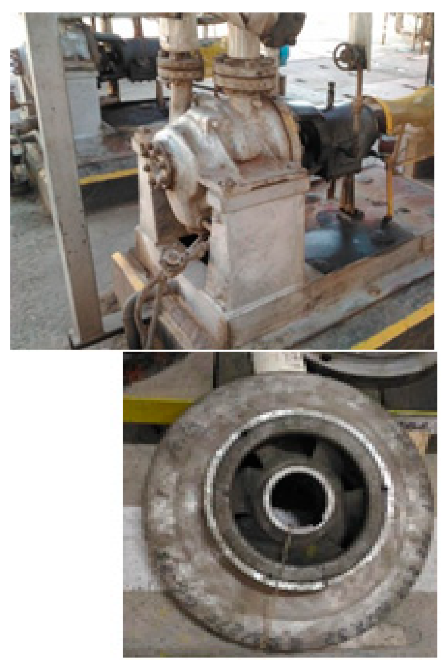
Figure 5.
The schematic diagram of the pump rotor (P-502B).

Figure 6.
Calculated response at impeller diameter = 0.254 m for API unbalance, normal bearing clearance.
Figure 6.
Calculated response at impeller diameter = 0.254 m for API unbalance, normal bearing clearance.

Figure 7.
Calculated response at impeller diameter = 0.281 m for API unbalance, normal bearing clearance.
Figure 7.
Calculated response at impeller diameter = 0.281 m for API unbalance, normal bearing clearance.

Figure 8.
Calculated response at impeller diameter = 0.31 m for API unbalance, normal bearing clearance.
Figure 8.
Calculated response at impeller diameter = 0.31 m for API unbalance, normal bearing clearance.

Table 1.
Characteristics of shaft P-502B.
| Parameter | Value |
|---|---|
| Material | AISI4140 |
| Length (m) | 0.7 |
| Equivalent diameter (m) | 0.036 |
| Young’s modulus (N/) | 2.10 × 10¹¹ |
| Density (kg/) | 7850 |
| Mass (kg) | 5.6 |
| Polar inertia of mass (kg-) | 0.000939 |
| Diametric inertia of mass (kg-) | 0.2373 |
| Moment of inertia | 8.24 × 10⁸ |
Table 2.
Characteristics of impeller P-502B.
| Parameter | Value |
|---|---|
| Material | GG25 |
| Type | closed |
| Equivalent thickness (m) | 0.12 |
| Diameters (m) | 0.254–0.281–0.31 |
| Density (kg/) | 7150 |
| Mass (kg) | 4.3–5.2–6 |
| Polar inertia of mass (kg-) | 0.03467–0.05231–0.06153 |
| Diametric inertia of mass (kg-) | 0.017338–0.02422–0.03283 |
Table 3.
Dimensional specifications and extracted parameters in bearings.
| SKF6307 | SKF7308 | |
|---|---|---|
| Parameter | Value | value |
| (mm) | 57.5 | 65 |
| (mm) | 13.5 | 15 |
| Z | 8 | 8 |
| g (mm) | 0.051 | 0.053 |
| (mm) | 41.2 | 46.35 |
| 0.23 | 0.23 | |
| 3.05 | 3.08 | |
| 3.05 | 3.08 | |
| () | 0.31 | 0.28 |
| () | 0.24 | 0.22 |
| 0.216 | 0.215 | |
| 0.212 | 0.211 | |
| 0.9865 | 0.9866 | |
| 0.9869 | 0.9871 | |
| () | ||
| () | ||
| Limited Speed (RPM) | 12,000 | 10,000 |
Table 4.
Effect of impeller diameter on the amplitude of vibration and critical speed of the rotor.
| Diameter of Impeller (mm) | Amplitude of Vibration (m) | Critical Speed (Backward) (Rpm) | Critical Speed (Forward) (Rpm) |
|---|---|---|---|
| 254 | 0.198 | 13,480 | 14,646 |
| 281 | 0.380 | 12,909 | 14,437 |
| 310 | 0.401 | 12,493 | 14,184 |
Publisher’s Note: MDPI stays neutral with regard to jurisdictional claims in published maps and institutional affiliations. |
© 2021 by the authors. Licensee MDPI, Basel, Switzerland. This article is an open access article distributed under the terms and conditions of the Creative Commons Attribution (CC BY) license (http://creativecommons.org/licenses/by/4.0/).
Share and Cite
MDPI and ACS Style
Shooshtari, A.; Karimi, M.; Shemshadi, M.; Seraj, S. Effect of Impeller Diameter on Dynamic Response of a Centrifugal Pump Rotor. Vibration 2021, 4, 117-129. https://0-doi-org.brum.beds.ac.uk/10.3390/vibration4010010
AMA Style
Shooshtari A, Karimi M, Shemshadi M, Seraj S. Effect of Impeller Diameter on Dynamic Response of a Centrifugal Pump Rotor. Vibration. 2021; 4(1):117-129. https://0-doi-org.brum.beds.ac.uk/10.3390/vibration4010010
Chicago/Turabian StyleShooshtari, Alireza, Mahdi Karimi, Mehrdad Shemshadi, and Sareh Seraj. 2021. "Effect of Impeller Diameter on Dynamic Response of a Centrifugal Pump Rotor" Vibration 4, no. 1: 117-129. https://0-doi-org.brum.beds.ac.uk/10.3390/vibration4010010