Ground Penetrating Radar Investigation of Corvin Castle (Castelul Corvinilor), Hunedoara, Romania


1
Department of Civil and Environmental Engineering, Princeton University, Princeton, NJ 08544, USA
2
ArchaeoTek: Archaeological Techniques and Research Center, Ottawa, ON K1K 4J7, Canada
*
Author to whom correspondence should be addressed.
†
These authors contributed equally to this work.
Heritage 2019, 2(2), 1316-1349; https://0-doi-org.brum.beds.ac.uk/10.3390/heritage2020085
Submission received: 14 March 2019
/
Revised: 15 April 2019
/
Accepted: 22 April 2019
/
Published: 6 May 2019
(This article belongs to the Special Issue Geophysical Surveys for Archaeology and Cultural Heritage Preservation)
Abstract
:Corvin Castle, located in Hunedoara County (Transylvania), is an important Romanian cultural site. Originally, a fort constructed in the 14th century, it was first converted into a castle by Ioan de Hunedoara in the 15th century, frequently changing owners (with significant construction in the 15th and 17th centuries) until it was abandoned in the mid-19th century. After undergoing various ill-fated reconstruction efforts in the late 19th century, the castle reopened in the 1950s when the Romanian government renewed its interest in cultural sites and undertook a series of sparsely-documented archaeological investigations and conservation projects. Presently, restoration efforts require renewed investigation of Corvin Castle’s construction and history. Ground penetrating radar (GPR) is a promising tool for investigating the construction phases of heritage structures like Corvin Castle, where invasive methods are inappropriate and extensive historical modification has left incomplete records. In 2017, a comprehensive GPR survey of the castle was conducted. The survey recognizes features mentioned in texts, discovers previously unknown constructions, locates areas of moisture ingress around the courtyard, and identifies the extent and composition of the building foundations. Information gained from these scans, especially combined with printed sources, is an asset in planning restoration efforts and understanding the effects of past modifications.
1. Introduction
The field of heritage preservation and conservation is diverse, bringing together an impressive array of disciplines, sites, and objectives. Unified by the notion that historical sites are a singular resource that hold value beyond their physical nature, conservators attempt to ensure that heritage sites remain accessible and retain their historical agency for the future. These sites are irreplaceable and valuable in terms of cultural significance, as repositories of historical knowledge, and for the tourism revenue they provide. However, they often face an onslaught of challenges—from limited work time, funding, and personnel, to the complicated relationships between stakeholders, funding sources, and legislative bodies. From a physical conservation perspective, unknown details about materials, construction, and accumulated modifications can limit the scope and success of any project. Successful conservation projects must take all of these challenges in stride and leverage each piece of information and expertise available, ensuring that the sites they seek to preserve are not mismanaged and subjected to unnecessary, harmful, or irreversible changes.
1.1. Historical Background
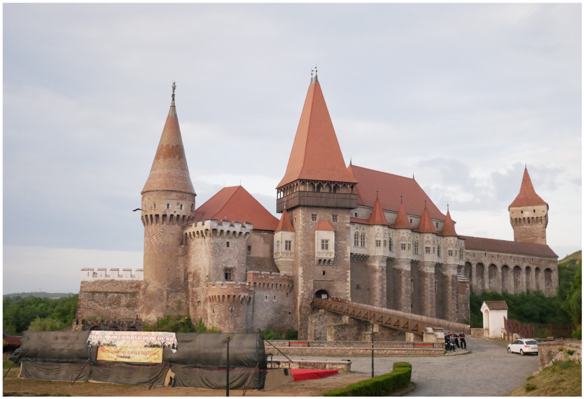
When it comes to a challenging and worthwhile conservation project, Corvin Castle is a ready example (Figure 1). Located on a bluff overlooking Hunedoara county’s Zlaşti River, the site has been occupied by various inhabitants over the millennia beginning in the Bronze Age [1]. Historical and archaeological research indicates that rich iron resources in the region facilitated trade routes passing from Alba Iulia, through Hunedoara, continuing south to Haţeg [1]. The first significant construction was a small, oval fortress with towers built sometime between AD 1299 and 13991, though the exact date is subject to scholarly dispute over the veracity of property documents drafted in the medieval period (refer to [1] vs. [3], as well as [4] and Figure 2). In either case, elements of the original fortress’ construction remain to this day. By 1409, Voicu Hunedoara was granted rights to the fortress and surrounding lands through the Donation Act of King Sigismund of Hungary [5]. Voicu’s son, Ioan de Hunedoara (alternately Iancu Hunedoara, János Hunyadi (Hungarian), and anglicized John of Hunedoara) inherited the estate and updated the fortress through two different construction phases, transforming the stronghold into a proper Renaissance castle [6]. By his death in 1456, the complex sported new, orthogonal outer walls and circular towers at each corner, as well as the Knight’s Hall, Diet Hall and the chapel [1]. The revered Hungarian king Matthias Corvinus inherited the castle after his father’s death and continued construction projects inspired by the Italian Renaissance in the northern wing of the castle until the end of the 15th century [1,2].
After Matthias’s son, John Corvin, died in 1504, possession of the castle went to the surviving widow, Beatrix de Frangepan who subsequently remarried and passed it on to her second husband George of Brandenburg. Brandenburg sold the castle to the Török family in 1526, and during that time there is little documented alteration besides the discovery of the foundation of a small structure in the southeast corner of the castle possibly built in the early 16th century [1,2,7]—see Figure 3. In 1613, Gabriel Bethlen, prince of Transylvania (1613–1629), gained possession of the Hunedoara estate and began a new era of reconstruction [6]. Throughout the 17th century, ownership of the castle was contested and passed frequently between the region’s nobility, including the Zolyomi family, who constructed the southern wing. After falling into possession of the Austrian state in 1724, the castle was variously converted into administrative housing or storage for an ironworks in the 18th century [1].
On 13 April 1854, Corvin Castle was struck by lightning, severely damaged and abandoned until Ludovie Arányí’s 1869 description of the castle revitalized interest in the structure [1]. Subsequent imaginative restoration works executed between the end of the 19th and early 20th centuries may have caused more harm than good, as original elements of the Western palace were destroyed and “faithfully” reconstructed by Ferenc Schulcz, while other elements were “restored” more creatively [1]—see Figure 4. By 1874, architect Imre Steindl had reimagined the monument and added roof tiles, archways, and the Ioan de Hunedoara statue atop the Painted Tower, raised the roof level with various vaulted ceilings, and contributed a variety of features (e.g., crenellations, a small tower) reminiscent of the castle’s origins as a fortification [1]. After 1874, architects replastered the insides and outsides of the buildings and recycled sculptural material as masonry [1]. Finally, in 1907, Istvan Möller restored the western and northern wings of the castle as accurately as possible, relying on archaeological excavations, drawings from L. Arányi, and rescuing repurposed fragments of sculpture from previous reconstructions [2]. Möller’s work was interrupted by the outbreak of World War I, when he was no longer able to continue work on the castle [2]. After Romania gained the territory of Transylvania through the Treaty of Trianon in 1920, the president of the Transylvania branch of the Romanian Historical Monuments Commission, Alexandru Lapedatu, decided to cease all restoration works in Corvin Castle [7].
A change in Romanian government led to a change in government policy regarding monuments and sites of historical significance. From 1956 to 1968, the state sponsored research and endeavored to restore each section to its historically accurate original state2 [1]. This effort investigated and successfully restored the Diet Hall (Sala Dietei), Knight’s Hall (Sala Cavalerilor), and chapel to commemorate the 500 year anniversary of Ioan de Hunedoara’s death in 1956 [1,3]. R. Heitel and the Department of Historical Monuments resumed restoration works and continued archaeological investigation from 1966–1967 in order to further academic understanding of the structure and continue conservation work begun in the 1950s. Though the results were never officially published, some of Floca’s 1956 archaeological report was later analyzed by Bogdan in an attempt to gather information on the evolution of the castle’s building phases, shown in Figure 3 [2]. After this period, the castle and surrounding complex have been the subject of a number of archaeological investigations and building updates, but no restoration campaigns focused on more than one wing or room of the castle. Archaeological excavations inside the castle (including the courtyard and sacristy) confirm the historical record of occupation from the 15th to 17th centuries, though excavations outside the walls of the castle find the archaeological record disturbed by the restoration works and construction debris of the 19th and 20th centuries.
Now, over 60 years since the last restoration work of Hunedoara Castle, the building needs continuing conservation work. Centuries of legends, muddled records, and interloping antiquarians have stifled proper scientific study and even damaged some elements of this important cultural landmark. New scientific advancements and international partnerships not previously possible are finally enabling researchers to fill in the gaps left behind by the historical record. The castle requires extensive scientific and historical research so that new, accurate renovations can take place in a timely fashion and the castle can continue to educate visitors. This work aims to begin compiling historical information, apply scientific techniques like ground penetrating radar (GPR), and integrate the results for an analysis that offers conservators important information relating the visible and invisible structures of the castle to its historical development.
1.2. Nondestructive Methods
Regular site evaluation and investigation practices include excavation, sample collection, and other invasive testing. Though these practices are accepted, invasive testing permanently alters the site or object being conserved and may not be desirable. For example, as excavation procedures and documentation have improved, they can reveal more and more information about a site; however, it is not possible to retroactively re-excavate an important site that was first excavated with very different means. This motivation has developed the field of nondestructive testing and evaluation into an increasingly robust set of techniques and tools to perform assessments and investigations of historic buildings. These include portable XRF (X-ray fluourescence) analyzers [9], ultrasonic testing [10], etc. In structural applications (for feature detection and resolution of targets larger than a few centimeters) methods like GPR, magnetometry, and photogrammetry are common [10,11,12]. These methods have the potential to provide information about a structure, ranging from the composition of pigment layers in paintings [9] to the mapping of foundation walls [12]. They are best used in concert with one another, as many of the methods provide complementary information that can be used to gain a fuller understanding of the investigated work. Increased applications of these tools can improve the methods and techniques themselves, as well as increase the appeal and familiarity of these methods to a broader audience.
Ground Penetrating Radar
Ground penetrating radar (GPR) is a nondestructive method of electromagnetic tomography, used commonly in a range of applications, including archaeological prospection and building surveys. It is an excellent method prized for its flexibility in subsurface inspection and noninvasive methodology. The method involves emitting pulses of an electromagnetic signal and recording the strength of the reflected signal as a function of time; the time series signal is called a trace or A-scan. A series of traces are collected along a line, or transect, to produce a radargram, line, transect, or B-scan. The signal is reflected when it encounters a contrast in electromagnetic properties like dielectric constant and conductivity. The stronger the contrast, the stronger the reflection. Since the dielectric constant is highly sensitive to moisture and air content, some reflections are caused by changes in these properties and not the physical materials themselves. Other times, strong reflections can indicate changes in material or composition, which are represented by high amplitudes of reflection in the traces and radargrams. If transects are collected at a consistent spacing, the lines form a grid which can be interpolated into a 3D data set and viewed as plan view “slices” of the grid area at different depths. These depth slices are particularly useful for interpreting linear features and, when combined with interpretations of the transects themselves, can provide clear visual indications of subsurface features. The size of the smallest resolvable features and the depth of signal penetration depends on the frequency of the antenna. Higher frequencies can resolve smaller features, but they cannot penetrate as deeply as lower frequency antennas because the signal is attenuated more quickly. In materials that are more conductive (wetter, higher salt or metallic content) or have high attenuation, all GPR antennas have reduced overall penetration depth. For further technical details, the interested reader is encouraged to pursue reference texts on the subject (e.g., [13,14,15,16]).
GPR is tremendously diverse in its applications, prized for providing rapid results (in real time for some applications) and being adaptable to a wide range of targets and site characteristics. These applications range from forensics, to civil infrastructure monitoring, to unexploded ordnance and geological resource mapping. Its use in the archaeological prospection arsenal is well documented, from forensic studies of Viking Age graves [17] to mapping Roman sites in urban contexts [18]. Similar to this work, GPR has been used to detect previous construction phases and crypts while mapping humid areas in cathedrals [19,20]. Additional works point to the potential of GPR to provide useful information about moisture ingress [21], subtle foundational and archaeological structures [22,23], and partially collapsed ancient walls [24]. As such, GPR is a natural choice to gather and verify important details about Corvin Castle’s history and physical structure. The castle is an enclosed, electrified, and paved space open to tourists; as such, the environment has particularly high background noise and confined spaces that impede equipment maneuverability over highly modified ground. Other non-destructive methods like electrical resistivity tomography (ERT) were not appropriate because of the solid floors, while potential field surveys (i.e., magnetic gradiometry) inside buildings are relatively absent from the literature and do not provide useful results in setting such as the castle. For these reasons, GPR was selected as an appropriate method of investigation over other ground-based techniques for subsurface investigation in complex urban environments.
1.3. Objectives
To perform documentation and assessment of the castle for this work, GPR was chosen because of its ability to provide the desired information, the interpretability of the results, and the availability of the equipment and resources to perform the study. We conducted a GPR survey of the castle, prioritizing the older and public spaces to understand the extent and character of different construction phases, substructures, and embedded elements. Additionally, GPR may be able to identify previously unknown features of the castle and provide details that can help align various historical accounts and records. The data serve as a resource for future investigations and restoration projects at the castle, as well as in applied GPR research3. All of this information is of interest to both conservators and historians of the castle in their future work maintaining, restoring, and safeguarding the castle for future generations.
2. Materials and Methods
2.1. Data Collection
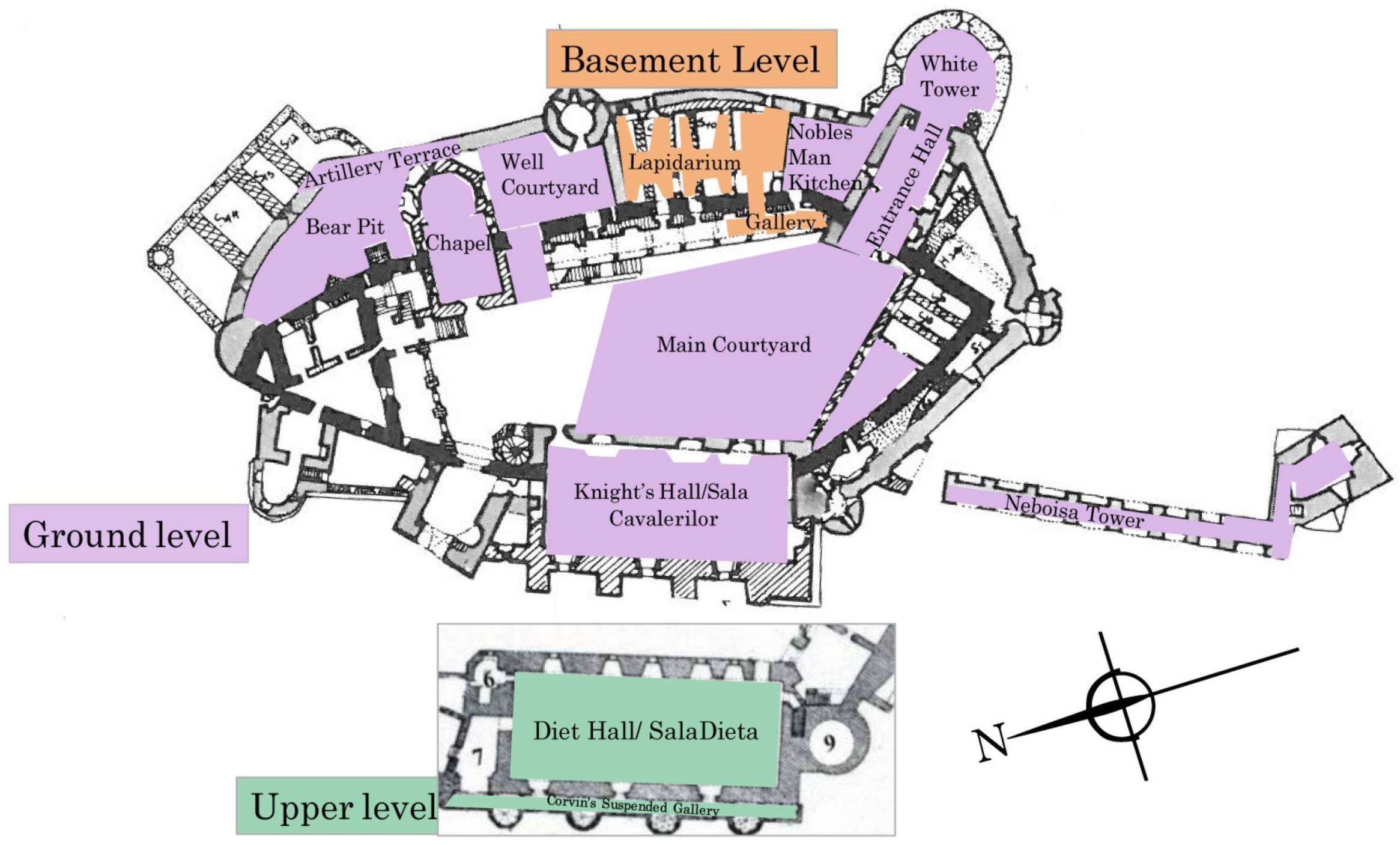
The survey of Corvin Castle was planned and conducted in the summer of 2017. With castle management, areas of priority including public and private rooms and courtyards were identified. These areas are described in the castle floor plan below and in the following summaries (Figure 5). All data were collected by ArchaeoTek field school teams under the supervision of Isabel Morris and Andre Gonciar in bi-directional (X and Y) orthogonal grids so that depth slices could easily be generated to aid in interpretation. For full coverage of the scanned rooms, multiple grids were collected in each room and then stitched together in the EKKO 5 project software (Sensors and Software, Mississauga, Canada). The data were largely collected at line spacing between 25–50 cm, with some exceptions collected at the spacing of floor tiles. A Sensors and Software Noggin 500 MHz antenna in Smart Tow configuration was used for maneuverability and the ability to scan smaller areas, though the physical configuration of the survey wheel/odometer requires at least 20 cm clear before the start of each line and therefore can limit coverage in some situations.
Assorted walls of interest were scanned in addition to large floor and courtyard areas, particularly in the Northeast sector of the castle (including the Bear Pit and Well Courtyard). These scans of vertical surfaces were primarily conducted to identify embedded elements indicating walls that were constructed at different times and belong to different phases. For example, vertical scans can locate a former staircase embedded in a wall by identifying reflection patterns of different construction material and technique in the shape of stairs (refer to Figure 4 and the wall in the background of the image of the well in 2.4.8 Northeast Sector) These scans were conducted as appropriate for each segment, aiming to collect three horizontal lines (parallel to the floor) at 50–100 cm spacing and additional vertical lines (scanned from top to bottom) collected at 25 cm spacing.
2.2. Processing
All GPR data processing was conducted using Sensors and Software EKKO Project with SliceView and LineView modules. In most cases, standard processing and filtering was applied; exceptions are noted in the results. The slices and lines are interpreted cooperatively in the SliceView module, which facilitates examining the data in both forms simultaneously. For lines (greyscale), processing steps during interpretation includes dewow and SEC gain (whose parameters are automatically determined). In depth slices (color), the processing includes dewow, migration, use of amplitude envelope, and automatic SEC gain. Initial interpolation between lines is done bi-directionally; this interpolation scheme produces the two-directional smearing of strong amplitude reflections into plus- or star-shapes Other interpolation schemes reduce these artifacts of data processing, though they were not available or necessary for this project. Interpretation of some grids is improved by using only one direction of lines; single-direction depth slices are noted and presented for some grids. These reasons include bias from different line spacing in each direction, orientation of features in the scans like floor tiles or columns, and directionality of the surrounding environment, which might include anything from electrical wiring to agricultural furrows. The display settings (contrast, sensitivity) are not adjusted. Basic processing steps were sufficient for most of the surveys and it was not necessary to apply additional filters or processes to reduce site-specific noise and interference. Note that, for radargrams, all horizontal axes are shown in meters and vertical axes representing depth are shown in meters, converted from two-way travel times with a nominal velocity of 0.1 m/ns, which was verified when possible using approximate depth information from excavation reports (in the Chapel, Entrance Hall, and White Tower). Depth slices are shown with the axes in meters.
2.3. Sources
Though few sources pertaining to the structures and plans of Corvin Castle are available, GPR scans were cross-referenced with a number of historical reports and maps. A valuable early plan, drawn immediately after the fire in 1854 by a student of Friedrich von Schmidt named Franz Neumann, likely served as a reference for the restorations carried out by F. Schulcz. Neumann’s drawing of Corvin Castle is currently housed in the collections of the University of Vienna’s Department of History of Art (Institut für Kuntegeschichte der Universität Wien, Plansammlung) and is used here with permission. Möller’s 1913 map of the original fortress has survived through several publications, including Vatasianu’s 1933 overview of castle restoration projects [7]. The map, which shows features of the original fortress walls, was a highly influential sketch incorporated into later reports (including this report) and was used as a basis for archaeological research at the castle. Bogdan (1970) is perhaps the most comprehensive report ever published on Corvin Castle and supplied a stratigraphic report and update to Möller’s map that were crucial for this paper [2]. Images from Bogdan’s reports are included here with permission from Arhiva INP (Institutul Naţional al Partimoniului), Fond DMI (Direcţia Monumentele Istorice), Cercetri arheologice 1967. All images not otherwise attributed are by the authors. By examining the original fortress walls (as estimated by Möller and others) and the location of archaeological trenches (made available through Bogdan’s map), most features in the GPR scans could be attributed to a mapped feature. Additionally, most other available maps of the castle floor plan are derived from Bogdan and Möller’s maps. Wherever the maps did not provide enough detail to explain GPR reflections, information was gleaned through historical sources and archaeological reports. Vatasianu (1933), Velescu (1961), and Bogdan (1970) are the main sources available [1,2,7] 4. Roman and Tincu’s (2009 in Romanian and 2012 in English) report on the chapel provide invaluable information on the stratigraphy of the northeast corner of the castle [25]; the 2012 translation is one of the only sources printed in English [3]. There are a number of other sources that include the castle or a feature of the castle in either a specific investigation or as part of a more general survey, e.g., [26,27,28].
2.4. Summary of Scanned Areas
These summaries present the primary rooms and areas of investigation in this work. Necessarily, neither the summaries nor coverage of the fortress is exhaustive. The amount of information about materials and construction phases is often quite limited, except in rare cases like the chapel complex. Resources that do exist are sparse, often in Romanian, located in European libraries, or of unreliable merit. The investigations are concentrated in the older and more complex evolution on the southern half of the complex (bounded by the chapel on the east and the Diet Hall on the west). Therefore, they contain little of the 17th century expansion of Gabriel Bethlen and 19th century reconstructions on the North side of the castle.
2.4.1. Noble’s Man Kitchen (Bucataria Nobiliara)
In its present configuration, this room is a large space in which almost all phases of the castle coexist. The lower portions of the walls are constructed out of stone, transitioning to bricks and adding a layer of plaster higher up. Visible evidence of modification is common, with filled in fireplaces, the sprinings of an earlier vaulted brick ceiling, and even an exterior doorway which served as the 20th century public entrance to the castle. Many of these modifications and previous configurations are shown on maps, including the subdivision in Neumann’s 1867 ground plan and Möller’s plan of the 1446 configuration (Figure 2 and Figure 4). According to Bogdan (Figure 3), the west wall along the courtyard was part of the first fortress wall in the 14th century and the south and east walls that remain were likely constructed during Ioan de Hunedoara’s 1442 campaigns (Figure 6); the north wall belongs to Bethlen’s 1619 expansions [2].
2.4.2. White Tower and Entrance Hall (Bastionul Alb and Turnul vechi de poarta)
Much of the White Tower (Turnul Alb or turnul și poarta veche) and entrance hall remain unchanged from the original configuration. The entrance hall was part of the original 14th century construction, where it appears that Ioan de Hunedoara reused the fortress’ east gate and tower (Figure 7. Bethlen modified the shape of the tower so that it was a circular fortification and left the inscription “1619” in more than one window (Figure 3, [2]). The entrance hall has two barrel-vaulted brick segments and a hewn stone floor. There are a number of niches and “windows” along the entrance hall connecting to adjacent rooms, including the Noble’s Man Kitchen. Two of Bogdan and Heitel’s trenches from the late 1960s (H1 and H2) run through the floor of the White Tower from east to west. H1 is 15.2 × 1.5 m running through the center of the White Tower, and H2 is 12.4 m × 1 m and runs through the entrance hall (Figure 3, [2]).
2.4.3. Courtyard (Curtea)
Throughout its active history5, the courtyard has been in constant use since the original stone fortress was constructed in the 14th century (Figure 8, [1]). Evidence of Gothic stone door frames from the original fortress can still be seen today [2]. Besides these two Gothic frames cited by Velescu and Vatasianu, the 1967 investigation discovered two more semi-circular frames (and supposedly a fractured frame “nearby”) in the basement of the Bethlen wing 10–13 m north of the Eastern Gate Tower under the Neo-Gothic gallery and walkway that had been added in the 1870s along the east side of the courtyard [1,2]. Velescu’s reports indicate that there are massive stone blocks in the courtyard which attest to this fortress’ oval walls [1]. The most significant repurposing of the space was the 17th century administrative housing/complex constructed by the Zolyomi family during their construction of the castle’s Southern wing [1]. This complex was explored by Floca in a few archaeological campaigns, the results of which were never published, but were available in Romanian archives as references for Bogdan [2] and Roman and Tincu [3].
The courtyard is presently covered by an uneven shallow layer of fine silty soil (likely less than 20 cm) on bedrock, which is visible over about one third of the courtyard’s surface. The precise geology is unknown, though the underlying outcrop is most likely composed of metamorphic schists and dolomite [29]. The perimeter of the courtyard is paved on three sides and modern drains are installed on the eastern edge. The space generally slopes down towards the current entrance on the northern end, rendering this northwestern part of the courtyard damper for longer periods than the higher southeastern corner. The results of the courtyard GPR investigation and their comparison to the archaeological investigations were originally reported in [30].
2.4.4. Chapel Complex (Capella and Sacristy or Complexul Ecleziastic)
The chapel is a Late Gothic structure on the northeast side of the castle comprised of a typical narthex/entrance in the west, rectangular nave, polygonal apse in the east, as well as a choir loft over the narthex in the west and a sacristy to the north (Figure 9). Construction of the chapel began sometime in the 1440s, though the precise date is debated by historians. Roman and Tincu note Floca’s belief that the chapel was actually built atop an earlier structure—possibly a corner tower from the first fortification—that was demolished for the construction of the chapel and associated rooms around AD 1450 [3]. A continuous layer of plaster in the nave, apse, and the rooms added by Bethlen between 1605–1619 indicate remodeling of the chapel at that time, but most of the structural layout and elements are believed to be relatively unchanged. When the castle was repurposed as administrative space in the 18th century, a document from 1754 reports a plank floor, a new marble altar, and possible subdivision of the chapel into three chambers [3].
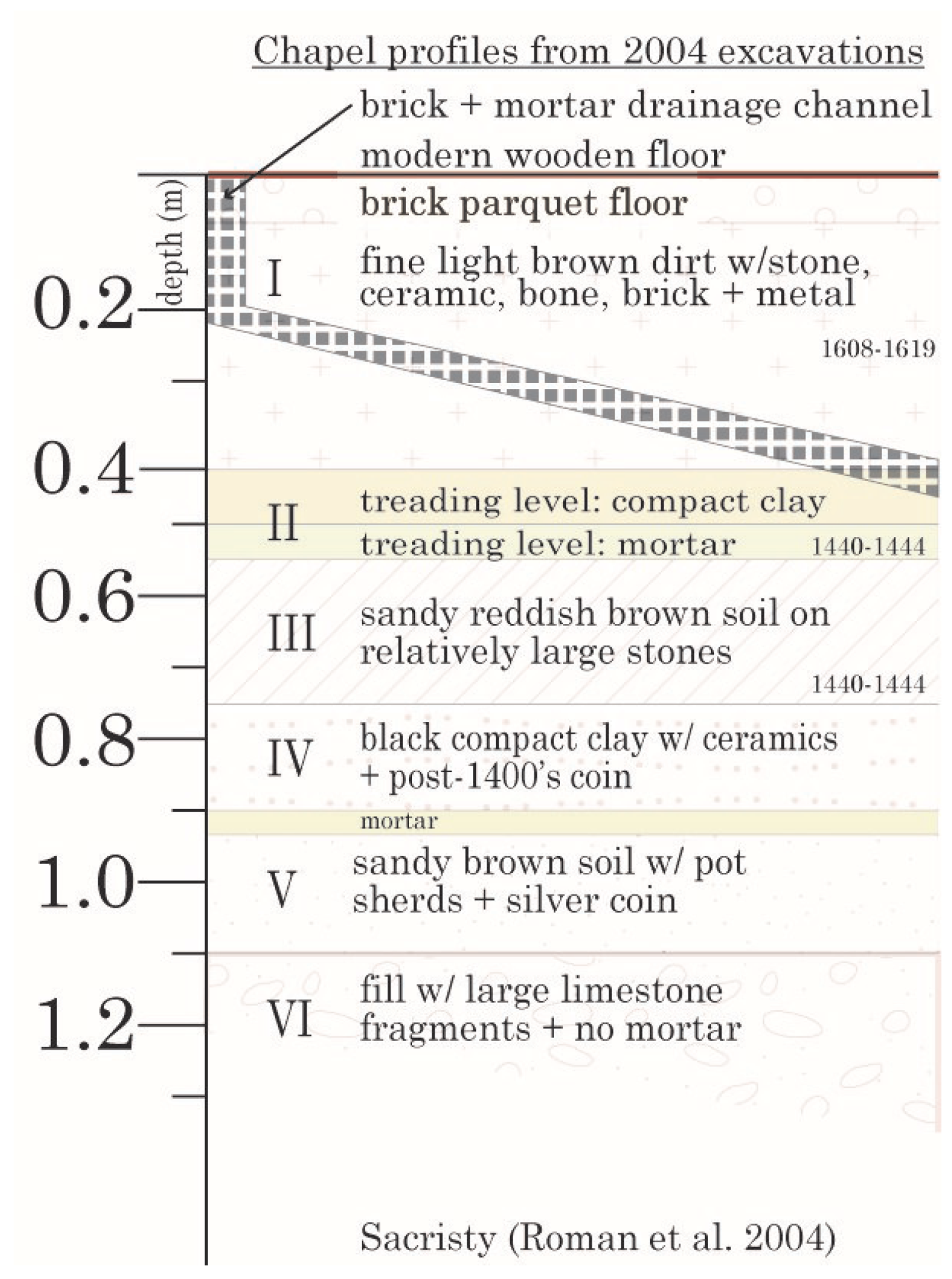
The ecclesiastical complex was excavated in 1956 by Floca as part of the Romanian restoration effort [3]. His excavation sought to determine if one of the chapel walls was part of the original castle construction by Ioan de Hunedoara in the mid-15th century, but was inconclusive. Floca’s report includes a description of an underground chamber lined with brick and stone that contained a bronze cross and two 17th or 18th century coins [3]. It is believed that Floca likely backfilled the chamber after he completed his work in the chapel [3]. Further excavations prompted by the installation of tourist facilities near the Sacristy were conducted by Roman in 2000. Many more substantial excavations took place in 2001 and 2002 when the stratigraphy of the sacristy was more clearly established (Figure 10, [31]). There is some speculation that a tower was built in the northeastern sector of the original fortress grounds but was demolished when the chapel was built in the mid-15th century [3]. According to data from Roman’s excavations, the northern section of the chapel was primarily built atop bedrock that was covered by a fill layer of black, compact clay [31]), except in the NE corner, where the bedrock slopes down and was covered by a layer of black humus [3]. These findings indicate a relatively consistent sequence of phases and strata for the chapel and Sacristy with the rest of the castle between the 15th–17th centuries (Figure 10, [3]).
2.4.5. Neboisa Tower (Turnul Njeboisia)
The Neboisa tower was built originally by Ioan de Hunedoara by the mid-15th century and has persisted to this day in its original form [1]. It served an obvious military function, standing five levels high on a 30 m hanging gallery and housing Serbian soldiers during the 15th century Ottoman invasion [7]; the name of the tower comes from the Serbian “nje boisia” meaning “do not be afraid.” The construction of the tower reflects this, with massive dolomitic limestone double walls that inspired the travelling Austrian topographer Josef Adalbert Krickel to comment that the tower was built such that “everything was skillfully arranged, so that any injury does not seem possible [32].” The gallery connected the tower to the main castle, with a room at the base for carriages to pass through and another walkway that connected it directly to the city, no longer standing [1].
2.4.6. Diet Hall and Knight’s Hall (Sala Dietei and Sala Cavalerilor)
The Knight’s Hall (ground floor) and Diet Hall (second floor, Figure 11) are the largest rooms in the castle. The Diet Hall (named for an assembly formed for the purpose of formal discussion or negotiation) was built in the 1450s and largely demolished in the 17th century [7]. During the 17th century, the Diet Hall was split into two levels and divided into three rooms, one of which was used to display paintings that were almost completely destroyed in the 19th century fire and following period of abandonment [1]. Restoration crews in the 20th century were able to rebuild the Diet hall from salvaged masonry in a style and plan that paralleled the lower Knight’s Hall, with a central row of octagonal columns. Using brick remains visible in the walls, they were able to recreate the Gothic vaulting and restore the original 15th century version of Diet Hall [1].
The Diet Hall rests atop the Knight’s Hall (Sala Cavalerilor), which also has a row of central columns and vaulted ceiling. Along the Diet Hall’s western side runs the suspended Galeria Huniazilor (Hunyad Gallery). The original size of the Knight’s Hall was roughly half its current size (Figure 2). It was expanded to the current size by Ioan de Hunedoara in the middle of the 15th century. During this remodelling, the gap between the original exterior wall and the new wall was left unfilled and accessible from a hatch in the floor of the Knight’s hall, which now forms a small cell [2]6. Significant partial restorations of the room were carried out by Schulcz (before 1874), Antal (1876) and Möller (1907) [1]. Today, the Knight’s Hall is in good condition, but there are depressions and cracking in the floor and humidity issues accumulating along the eastern wall along with the courtyard. Because of the courtyard’s slope, water drains toward the Knight’s Hall. There are three deep alcoves with windows on this wall, and there is persistent damage to the bricks, plaster, and other materials in the alcoves.
2.4.7. Lapidarium of the Corvin Museum and Gallery
The room currently used as the lapidarium of the Corvin Museum and its associated galleries is located on the south side of the Well Courtyard (containing the Turkish Well) underneath the Bethlen living rooms (Sufrageria Bethlen) along the eastern side of the castle (Figure 12). It is primarily constructed of 15th century brick and stone, likely the same dolomitic limestone used in other areas of the castle. Little is known about the lapidarium and its occupational history because it is apparently omitted from plans of the ground floor and prominent rooms located directly above it, but it could have been roofed and expanded upon to increase the footprint of the castle on a relatively consistent level. This space has been used as a lapidarium to display the stone monuments, architectural elements, and other carved fragments from the castle since the restoration works of the 20th century sought to salvage the original architecture of the castle [7]. Connected to the southwest end of the lapidarium is a closed in subterranean gallery, about which little is known.
2.4.8. Northeast Sector
These areas on the northeast corner of the castle closest to the Mace Tower (Turnul Buzdugan), primarily belong to the phases of Ioan de Hunedoara (1450’s) and Bethlen (1619). Included in this grouping are the Bear Pit (Groapa Ursilor), Artillery Terrace (Bastionul Munitiilor), and the small eastern courtyard that contains the Turkish well (fantana), called the Well Courtyard 7 (Figure 13). The Artillery Terrace was added by Bethlen, while the courtyard and Bear Pit were present in Ioan de Hunedoara’s original construction (Figure 2, [2]). The chapel was constructed in the castle yard, dividing it from the Bear Pit and the space which would be paved and leveled into the Well Courtyard. The courtyard itself is bordered by Ioan de Hunedoara’s original exterior wall on the east side and the older 14th century fortress wall on the west side.
3. Results
GPR surveys have provided important results for each of the areas presented here. In general, scans of the floors successfully reveal pavement levels, changes in floor covering, moisture patterns, and myriad substructures. In some areas, such as the courtyard and bear pit, features were more difficult to interpret. This is largely due to the uneven ground and surface debris in these areas. Asterisks (*) indicate that GPR scans of the area include a material change in the foundation of the indicated room; the foundations are discussed separately. In most rooms, the penetration depth of the antenna was estimated at between 1–1.5 m (using a velocity of 0.1 m/ns, which is appropriate for most of the castle and verified where possible using depths reported by excavations). Note that features are visible in very lightly processed data; this data is presented in an effort to provide a reference for continued study of the castle.
3.1. Noble’s Man Kitchen
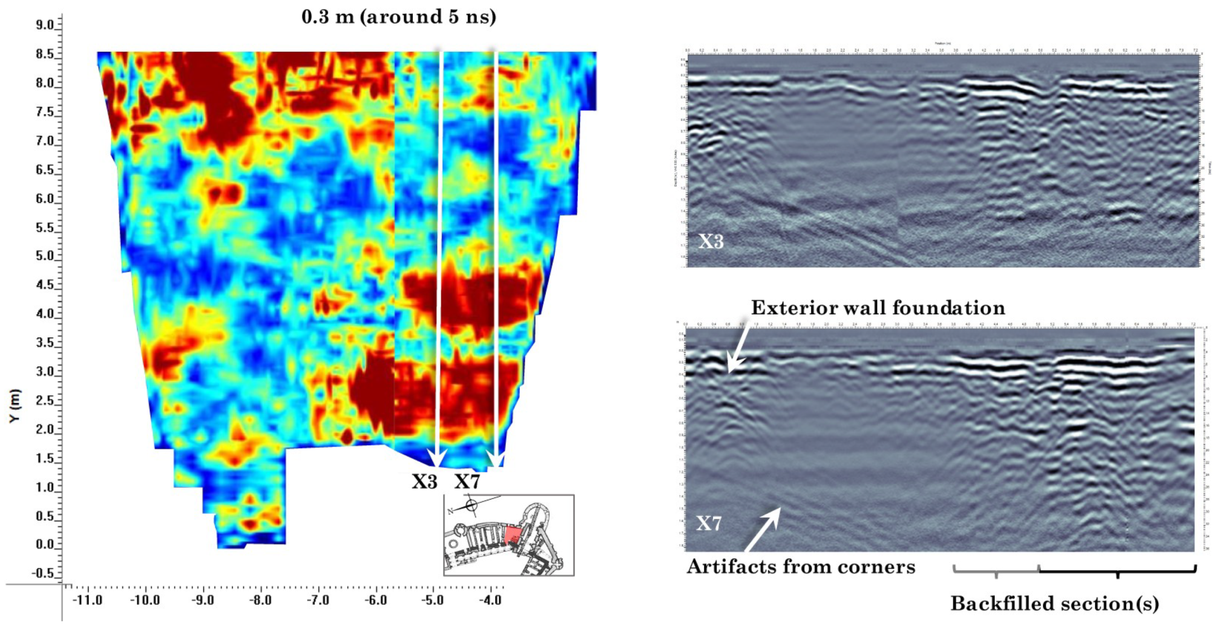
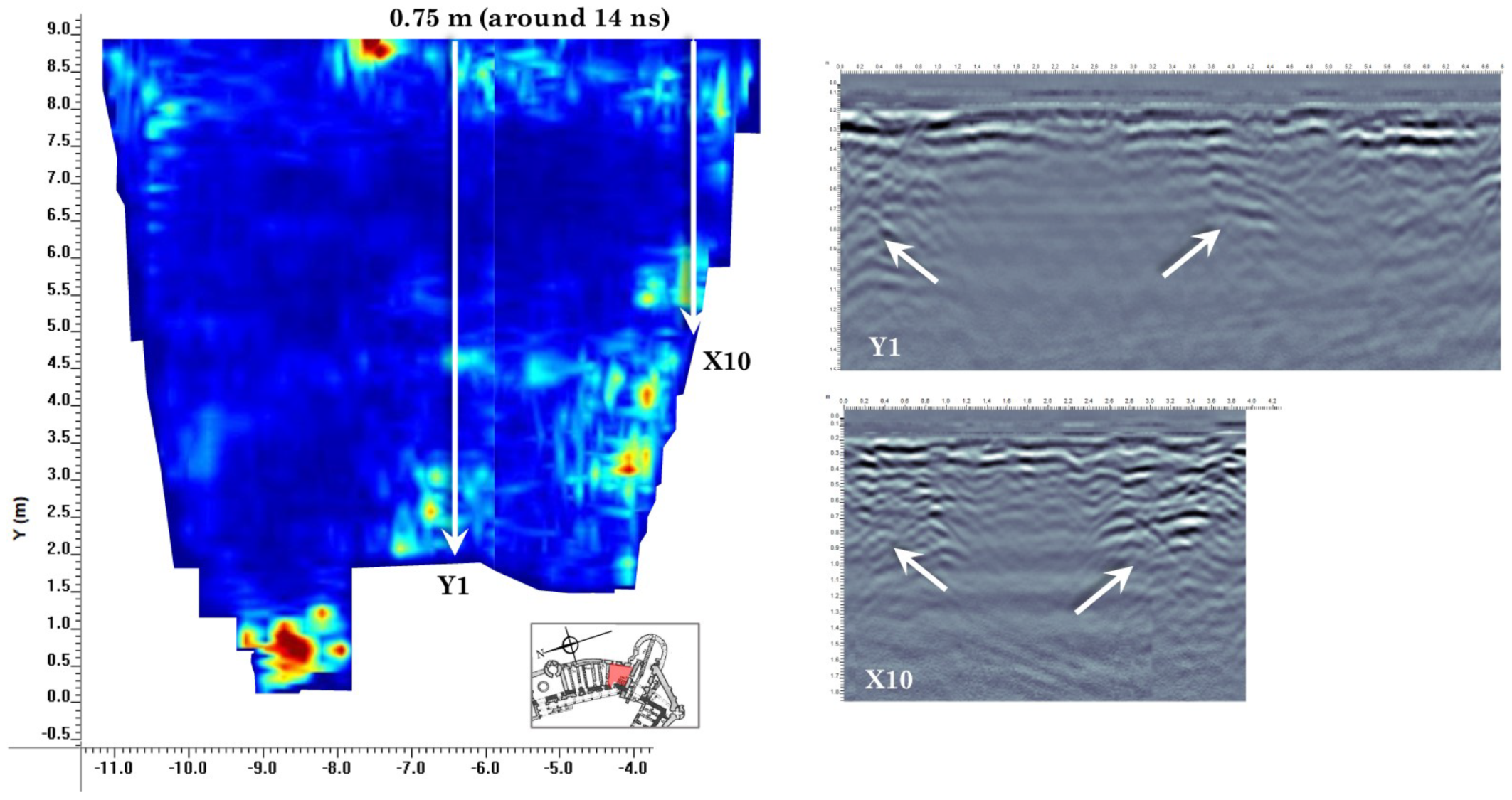
In GPR scans of the Noble’s Man Kitchen, the foundations of structures implied in early maps are present (Figure 2). The highly reflective area in the SW corner is caused most likely by both the backfilled excavation trench reported in Bogdan (“caseta T,” Figure 3 and Figure 14) and foundations of structures drawn in Figure 4. Just southeast of this section, there is an area that appears similar to the backfilled trench in the corner (an area of high reflection strength), but this is not reported in Bogdan and does not appear to extend as deeply (Figure 14). In deeper slices, there also appear to be at least two more wall foundations along the southern edge that may extend into the kitchen from the entrance hall (Figure 15). The longer segment closest to the eastern wall appears to be part of an older phase of the fortress, possibly an original exterior wall. The artificial air reflection at the exterior wall is also visible in the lines that begin perpendicular to that wall (Figure 14), accompanied by the strong shallow reflections from the paving and leveling surface of the floor. Note that the room was scanned in two grids which divide the room into a north and south half.
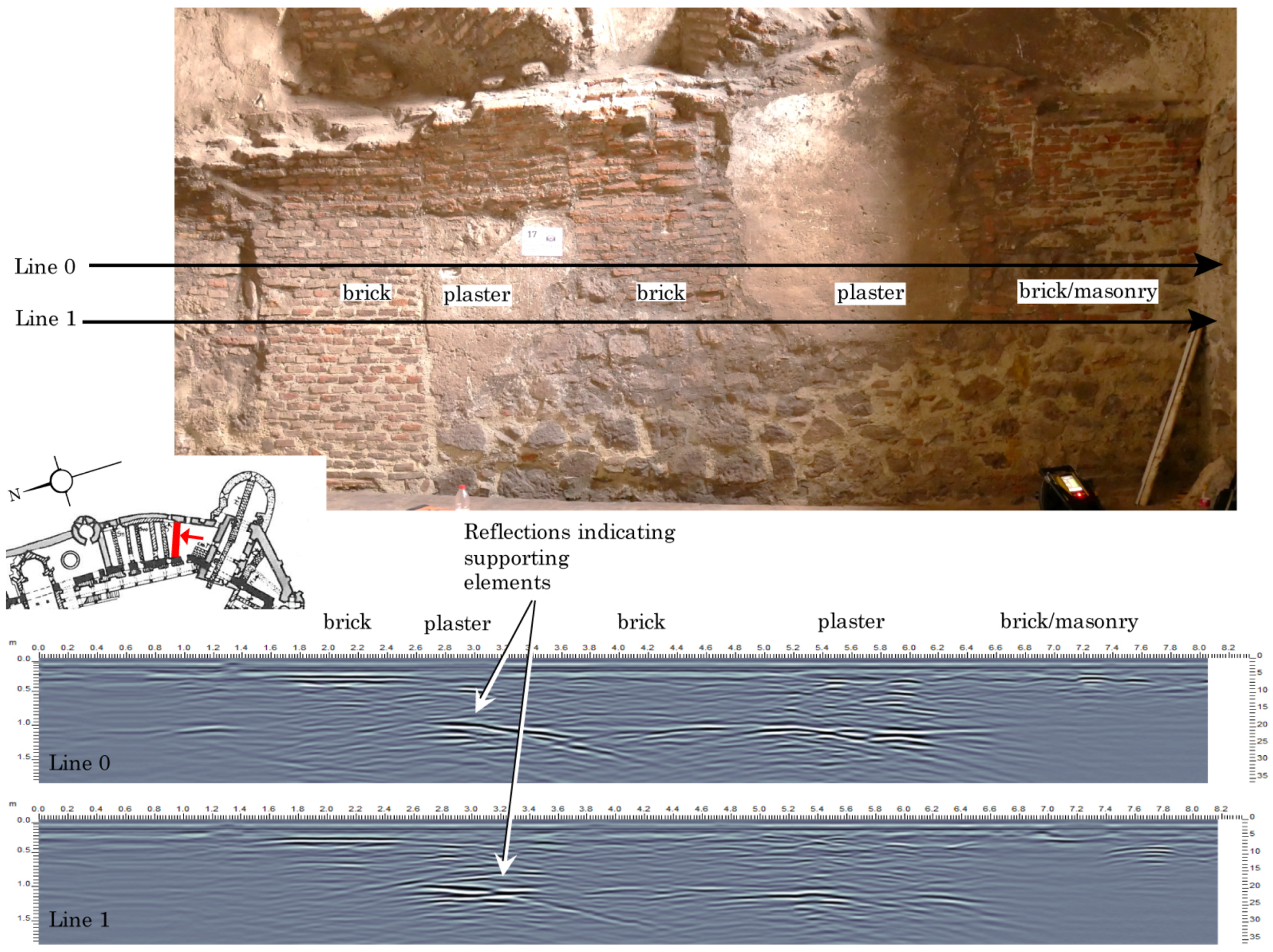
GPR scans collected on the four walls of the Noble’s Man Kitchen can verify the different materials and phases visible on the surface, while extending the knowledge of each of those phases to their complex subsurface interactions. Regular and irregular patterns of bricks, masonry, and plastered surfaces are distinguishable in depth slices parallel to the face of the wall, though close inspection of the radargrams themselves is more informative (Figure 16). The most important feature that is visible in these scans is the substructure of earlier phases visible below the outer face of the wall (Figure 16). These structures line up with the springings of the second-floor vaulting that are visible higher up on the wall, indicating that they are supporting elements or columns for the now-absent structure (Figure 16). The vaulted ceiling may have been ripped off by modern restorer in the 19th or 20th century, or by Bethlen in the 17th century, as he did with the vaulting in the chapel and Knight’s Hall [7].
3.2. White Tower and Entrance Hall
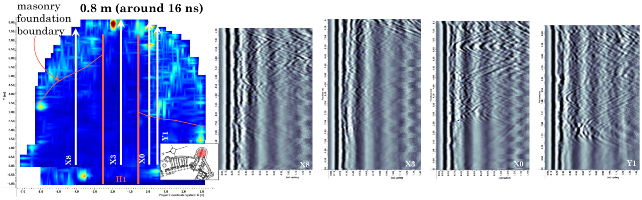
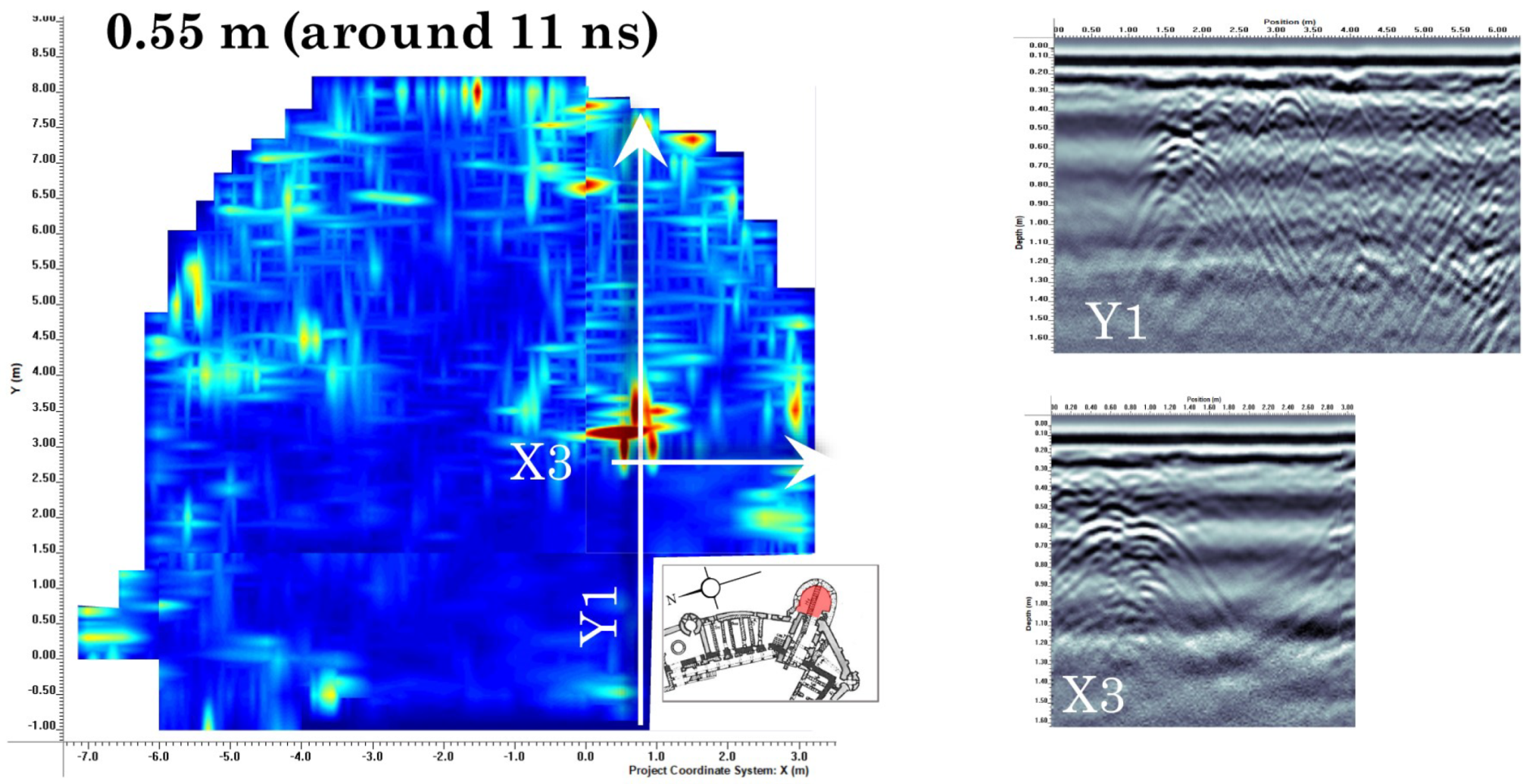
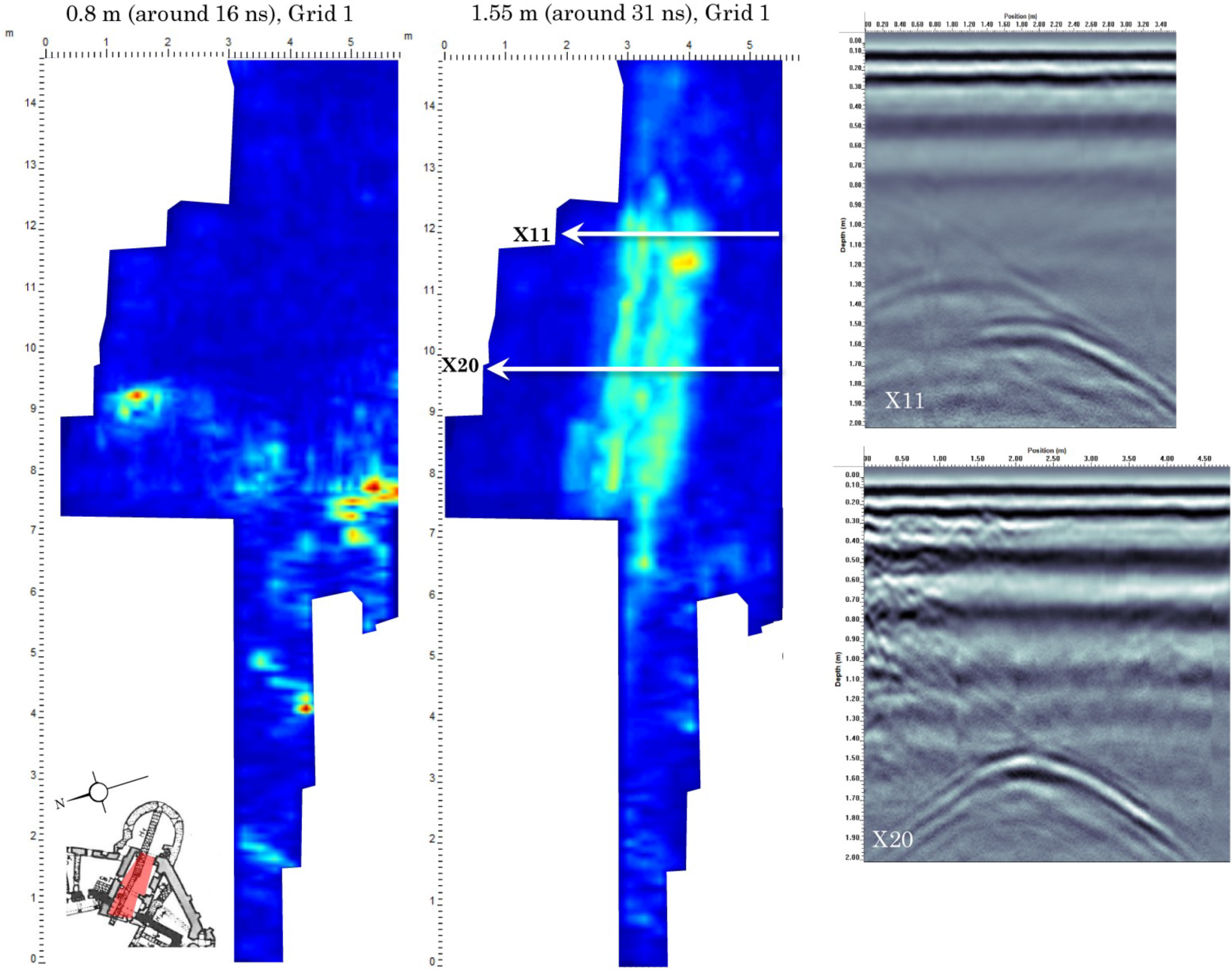
The White Tower and former entrance hall of the East Gate contain a number of interesting features, the most prominent of which are Bogdan’s backfilled trenches from 1969. These trenches run east–west through the middle of the entrance hall and tower for their entire length (Figure 3). According to Bogdan, most of the entrance hall and tower lie on a shallow layer of leveled fill (from the 14th–18th c.) reportedly resting atop bedrock (Figure 17), while the tower lies partially on an extended stone or brick foundation [2]. This foundations is verified in the GPR scans (Figure 18). In the tower, there is a strong reflection in the central east side, likely an air void or large stone block, possibly related to the excavation and backfilling of the 1969 trenches (Figure 19). The tower also contains a signature of Bogdan’s excavations, but of a different character from those in the entrance hall. In the tower, the trench appears as an area without reflections, indicating strongly attenuating or conductive backfill (Figure 18). The exact spatial delineation of the foundation reported by Bogdan was unknown outside the confines of the 1969 trenches, but can be mapped across the tower from the GPR scans, where the foundation is clearly differentiated from the bedrock (see Section 3.9 Foundations)). Note that the tower was scanned in three grids stitched together for full coverage of the floor area; individual scans (e.g., X3) represent the size of a specific grid rather than reflecting the dimensions of the tower.
In the entrance hall connecting the tower to the courtyard, the strongest and deepest reflections are those aligned with Bogdan’s backfilled trenches (Figure 20, [2]). Note that the backfill for the trench H1 appears as a “dead zone” and the bottom of the trench is less visible in the GPR scans, while the bottom of H2 is more visible (Figure 20). This could indicate H2’s shallower depth and different backfill material in each trench (H2 with lower attenuation). Running perpendicular to the trench, there are significant features that likely belong to earlier phases of the castle, “probably built on the site of the old gate of the first fortress [2]”. First, there is a strong dipping reflector across the center of the entrance hall that is roughly in line with one of the short wall foundations in the Noble’s Man kitchen (Figure 14 and Figure 21). More subtle is the reflection of two additional wall foundations closer to the courtyard, which are aligned with the original 14th century fortress as shown in solid black on the Möller and Bogdan maps (Figure 22). These walls or features do not appear in the drawn profiles from the 1969 excavation, though there is significant debate surrounding Bogdan’s conclusions in this room. Some debate centers on the trenches stopping at bedrock, with the possibility that the trenches stopped before bedrock and actually report depths to an architectural feature, perhaps a now-filled cellar as mentioned by Krickel [32,33]. Without further excavation, the reflections in these radargrams and the features themselves cannot be definitively understood. Across the hall itself, the floor material changes at around 7 ns in the GPR scans. At a nominal velocity of 0.1 m/ns and with a time-zero correction, this would indicate a level of at least 20 cm. Because the paving was added after Bogdan’s excavation and is not included in his profiles, the velocity cannot be confirmed, but it reasonable and useful nonetheless.
3.3. Courtyard
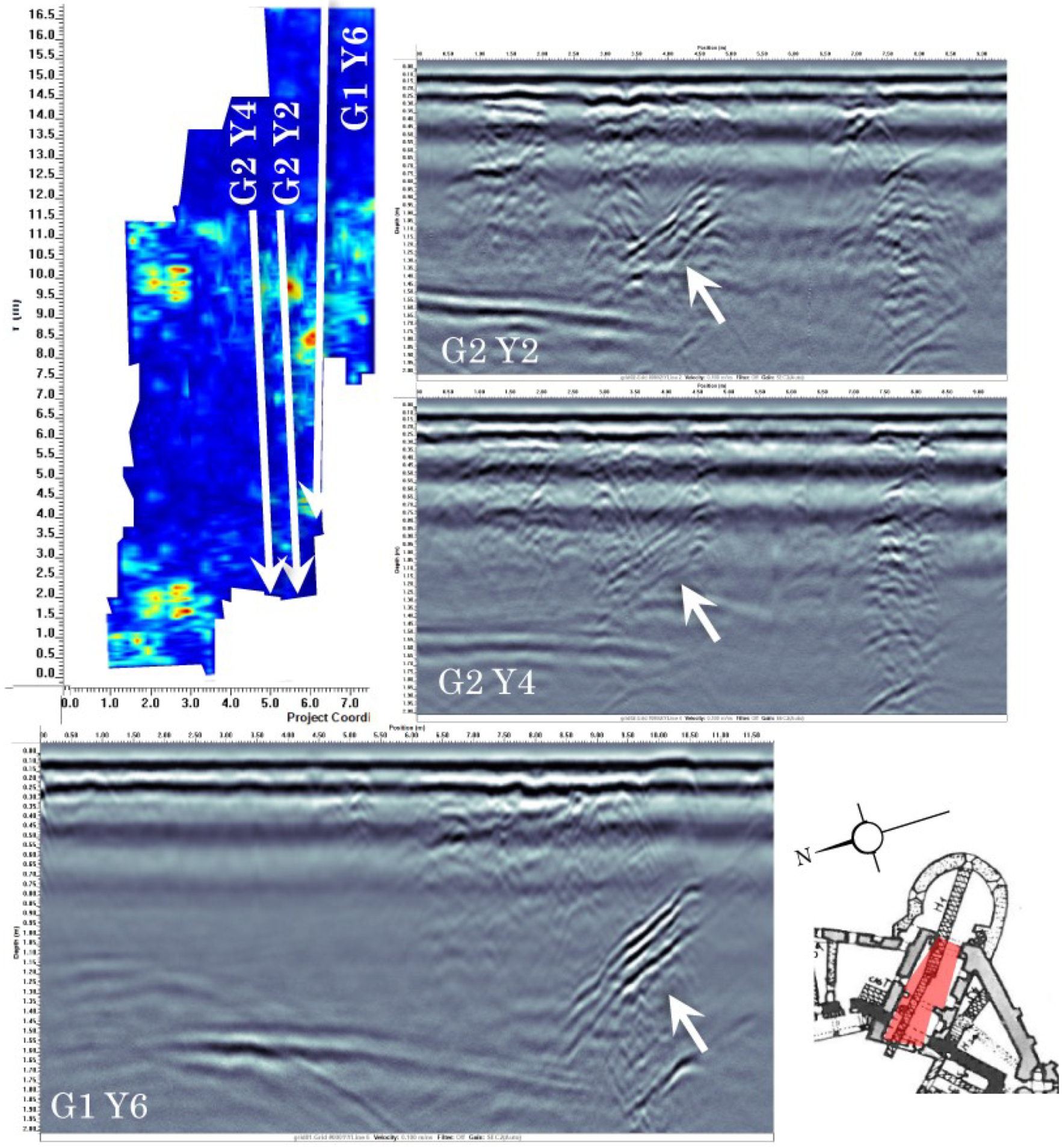
In addition to mapping the light silty soil coverage across the courtyard (nominally 20 cm, with most areas shallower) and metamorphic features in the bedrock, the scans in the courtyard identify reflections that may correspond to the foundations of earlier structures, including the administrative complex and early phases of the castle (Figure 23). The structures related to earlier constructions are located primarily in the southern half of the grid. For example, there are strong reflections in the western (lower right hand) corner of the grid that correspond with a staircase drawn by Neumann in 1867 when he was an architecture student at the University of Vienna (Figure 4) and a small gate which Vatasianu claims was repurposed by Ioan de Hunedoara [7]. Reflections from the bedrock in the courtyard is readily recognized in these scans, which enables identification and characterization of the foundations in surrounding rooms of the castle from the GPR scans. This helps to demarcate areas in other rooms where the foundations of the fortress have been extended with other materials (likely masonry, as in the profiles from Bogdan, Figure 17). The results presented here are extended from the results presented in [30].
3.4. Chapel
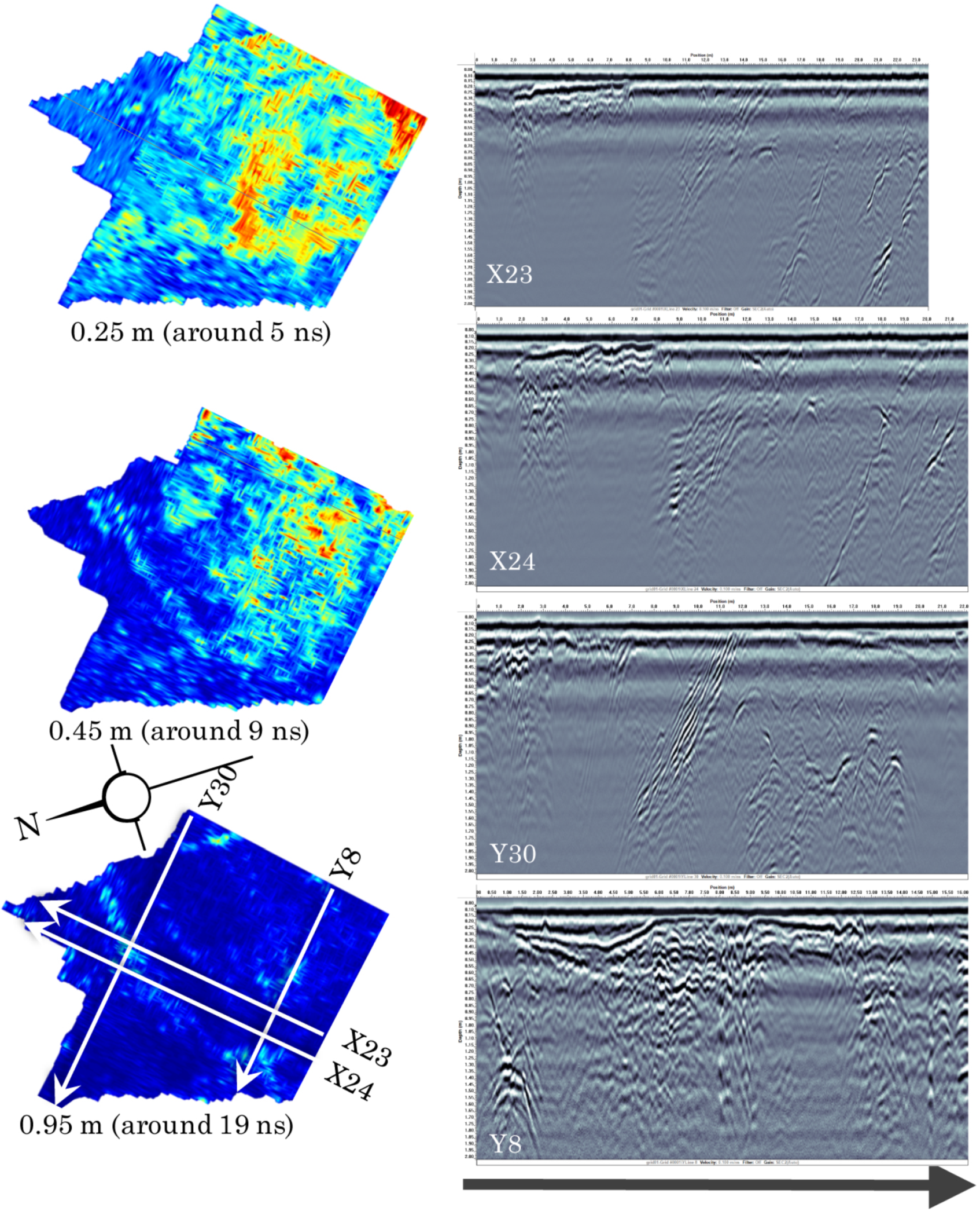
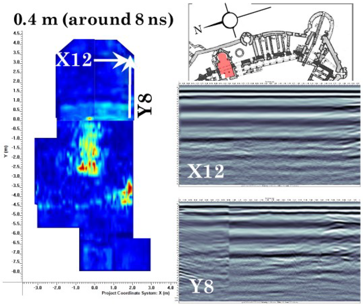
In addition to being the area with the most complete and recent documentation, the chapel has many features that are positively identified and verified in GPR scans. Visible immediately below the current level of the floor in the center of the chapel is an underground room, most likely used as a crypt and later filled with construction and remodeling debris. In GPR scans, the chamber is approximately 1.25 m wide and 2.5 m long, with approximately 1 m of clear space between the floor and ceiling (Figure 24). According to Floca’s 1956 excavation results as reported in Roman and Tincu 2009 and 2012, the actual dimensions of the “underground room” are 1.15 m wide by 2.55 m long by 2.40 m deep [3]. The crypt is located in the center of the chapel at the east end of the nave. The western portion of the crypt contains many reflections which indicate two possibilities: first, that this portion of the crypt is filled with large debris; second, that the western boundary of the crypt is composed of the original 14th century fortress wall (Figure 24, especially lines X8 and Y8). In either case, most of the crypt is filled with debris material from Bethlen’s 17th century reconstructions through Floca’s 1950’s archaeological backfill [3]. According to Möller’s plans of Corvin Castle and confirmed by GPR, the original fortress wall should run through the center of the chapel at approximately the western edge of the crypt (Figure 2, Figure 3 and Figure 4)8. Roman and Tincu notes in a footnote that the west wall of the crypt may be composed of brick from the original 14th century fortress which became available as the chapel evolved [3]. Because GPR evidence indicates that the western end of the chapel is markedly different from the rest, GPR may confirm the inclusion of the 14th century wall in the western wall of the crypt and not as one of the walls of the chapel, as imagined by Floca.
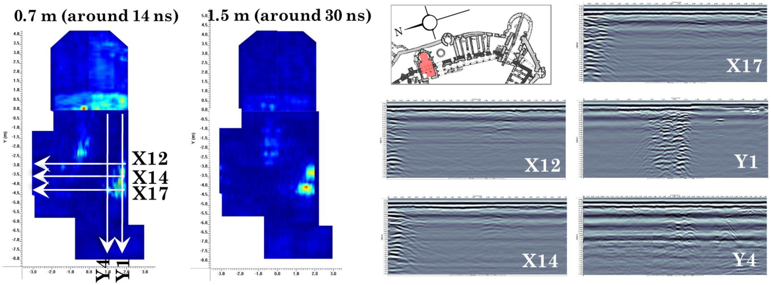
Aside from the crypt, GPR scans indicate wall foundations from earlier phases along the southern wall of the chapel (shared with the Well Courtyard). Two foundations appear in the nave of the chapel, just west of the crypt along the wall (Figure 25). These are also aligned with the original fortress boundary and should be associated with that phase. The eastern-most reflections may be related to the 1956 restoration excavations [25]. The foundations visible in the southern corner of the apse are located at the intersection of the chapel with the edge of the courtyard, where there are now stairs leading into the Bear Pit (Figure 26). This detail is included in most plans of the chapel besides those of Bogdan (Figure 2, Figure 3 and Figure 4), and the reflection may be related to the appearance of the staircase. Also note the “ringing” effects on the radargram (localized columns of black and white stripes) from a strip of iron installed in the floor and the carpet between the apse and nave and the artifacts from corners, as in Figure 14 (Figure 24, line Y8). Deep on the west end of Y4 lies an unexplained reflection. It is not in line with the columns but some documentation could give more context. Roman and Tincu [3] look into the Floca excavations in 1956 which mentioned another brick pavement on the Western enclosure of the chapel, 18 cm below the known 15th century brick pavement. Floca believed that the older bricks might have belonged to a 14th century fortress tower that was torn down, though Roman and Tincu express hesitation about his hypothesis. Unfortunately, Floca’s notes were unclear as to whether he had left the brick in situ or dismantled the flooring. Additionally, in the year 2000, archaeologists investigated the west wall of the Sacristy (located north of the narthex) and found sandstone slabs that served as steps −0.2 to −0.33 m (west to east) under the current treading level. The reflection in Y4 must be related to one or more of these features.
3.5. Neboisa Tower and Gallery
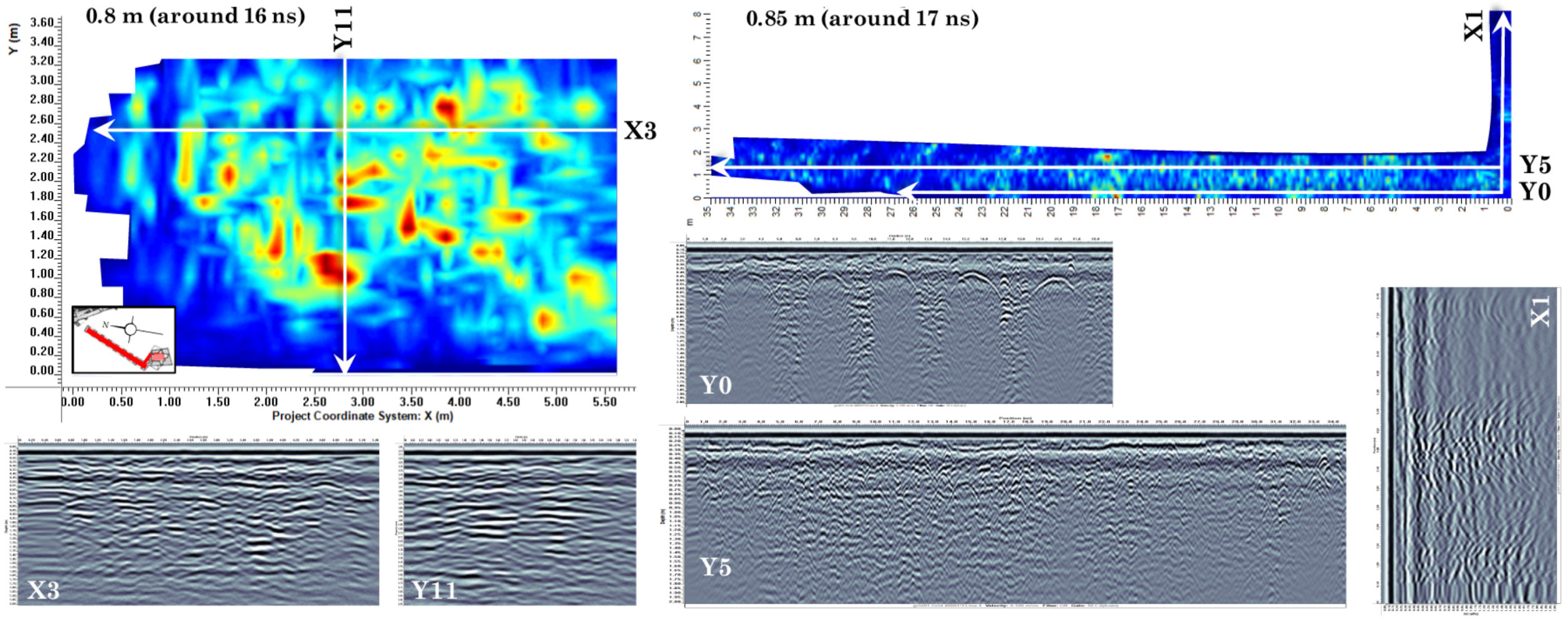
The iconic tower and gallery of Neboisa have readily recognizable reflections in GPR scans. Because the tower’s substructure has remained largely unchanged since its construction by Ioan de Hunedoara, the only reflections visible are of the brick and stone construction (Figure 27, [7]). Laterally, the GPR scans indicate that the supporting structure of the walkway and tower does not consist of walls sandwiching fill, but of solid masonry. Note that in lines at the edges of the gallery (e.g., Y0, X1), the arched buttressing is visible. This is also present, more subtly, in line X1. X1 changes character towards the end of the scan because this is where the gallery joins the tower, so the GPR signal is also dispersed throughout the tower substructure rather than being isolated on both sides by the surrounding air, as in the rest of the gallery.
3.6. Diet Hall and Knight’s Hall
Scans of the Diet Hall clearly show the variable depth of the floor and quadripartite vaulted ceiling of the Knight’s Hall below. These patterns are especially pronounced along the axes of the grid defined by the columns in the Knight’s Hall (Figure 28). Note that the line of blue in the depth slices is the unscanned area between the central columns. Though the scans of this room appear markedly different from other scans of the castle, the survey parameters and collection method are the same in the Diet Hall as other rooms. The differences are primarily caused by the nature of scanning a ceiling, where there are clear reflections from a single integrated level with air on both sides. The ceiling was restored in 1874 by Schulcz and later by the Historical Monuments Directorate (1966–1969) [1,2]. The extent of the latest restoration is unclear, though the reflections indicate that the ceiling may be made (at least partially) of reinforced concrete (Figure 28, especially X26).
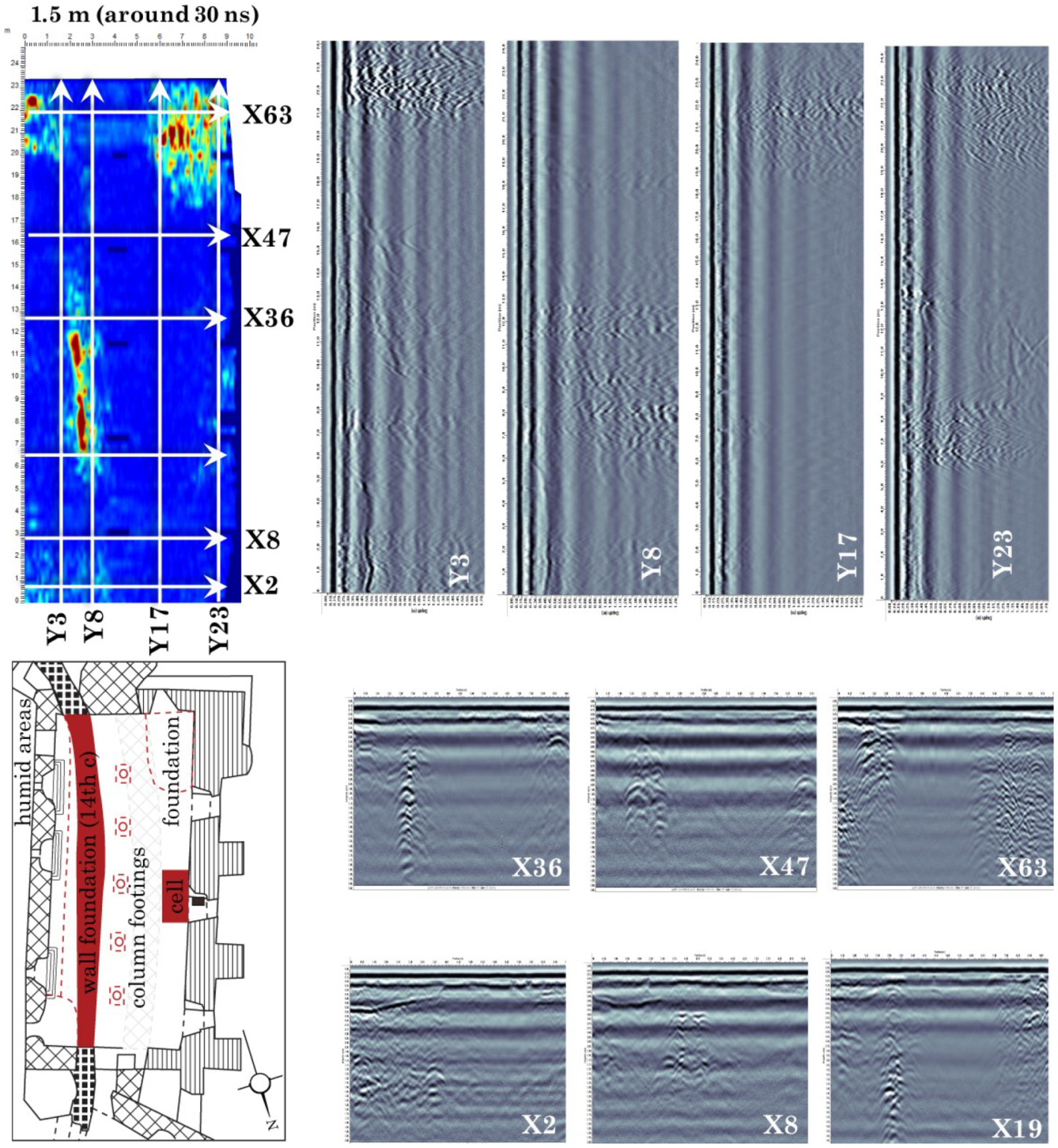
In the Knight’s Hall, GPR scans reveal the complex evolution and expansions of the castle to the west, including part of the original 14th century fortress, a small underground chamber, and clues about the foundations of the castle. In most plans of the castle, both the 14th century fortress and Ioan de Hunedoara’s 15th century expansion pass through the modern Knight’s Hall (Figure 3). The 14th century fortress (shown in dashed lines in most plans) has a jagged appearance, indicating that its actual trajectory is unknown. In GPR scans, the path of the wall appears to follow the same overall trajectory, with a change in construction style rather than a “jog” present near the center of the room (Figure 29, compare lines X36 with X47 and X63); note that these reflections are consistent in the x-lines, but inconsistent in the depth slices. This is caused by a combination of different materials and construction styles that is accentuated by uneven depths of the remaining wall foundations and the interpolation between the scans that create the depth slice. The 15th century wall (west of the 14th century wall) does not clearly present itself in the GPR scans, confirming written accounts of its removal by Ioan de Hunedoara (Figure 29, esp. lines X19 and X36, [1]). This could indicate that these two phases share the same foundations, that the later construction completely replaced the original, or that substructures west of the 14th century wall were removed during later renovation of the castle. This area is an excellent candidate for more focused investigations.
In addition to this significant wall feature, there are a number of other notable reflections in the scans. The dimensions of an empty cell (celule) accessible from the Knight’s Hall can be seen in the center of the Hall along the western wall (Figure 29, esp. lines X36 (end) and Y23 (center, look for the faint “x” at the bottom of the scan)). The footings of the columns (X8), the foundations of a spiral staircase just outside the SE corner of the hall and next to the 14th century foundations (end of Y3), and strong early-time reflections around the alcoves and entrance on the eastern wall (beginning of most x-lines and beginning of Y3 and X2) can be seen in Figure 29. The early time reflections along the courtyard side of the room are evidence of moisture ingress in these areas, supported by visibly damp walls on this side. Water drains down the slope of the courtyard and accumulates in the shallow depression along this wall, where it soaks into the walls and foundations of the Knight’s Hall. Finally, there is confirmatory GPR evidence that portions of the castle’s modern foundations were built up in its exterior, which is visible in the SW corner of the hall (see the ends of lines X63, Y17, and Y23 Figure 29).
3.7. Lapidarium of the Corvin Museum and Gallery
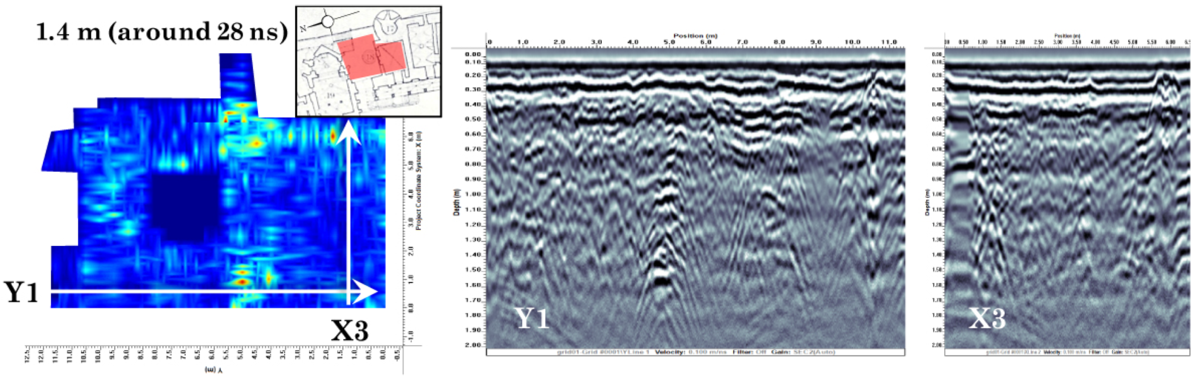
These two conjoined rooms exhibit a number of interesting features, but due to the narrow architecture and floor plan with only small areas of continuous space, walls and other structures are difficult to identify in depth slices. Once again, foundation materials and construction techniques vary across the room, with bedrock near the center of the complex and built up foundations in the northern and southeastern portions (Figure 30, especially y-lines). In the built up foundation sections, some reflections resemble more vertically coherent wall foundations (especially in the attached gallery on the SW side) and the foundations of the room’s walls in the north end (lines Y6 and Y3G4*, Figure 30). Deeper features are also present (1.2m depth slice in Figure 30). Across the center of the lapidarium running east–west is what is perhaps a drain due to its strong reflection and placement (i.e., center of Y6, Figure 30). Also visible in the deeper slice are similar reflections at the edges of the room (in beginning of X10, end of X3, and X3 G4*, Figure 30). Note the artificial reflections as in Figure 14 from the air wave inside the corner of the room. It is possible that these are related to features mentioned in Bogdan’s excavation report, such as the two Gothic arches and his suspicion of a garrison attached to the NE side of the early fortress. The locations of these features from excavation are unknown, so the identity of these particular reflections is still unknown, though there is now additional evidence to motivate further investigation.
3.8. Northeast Sector
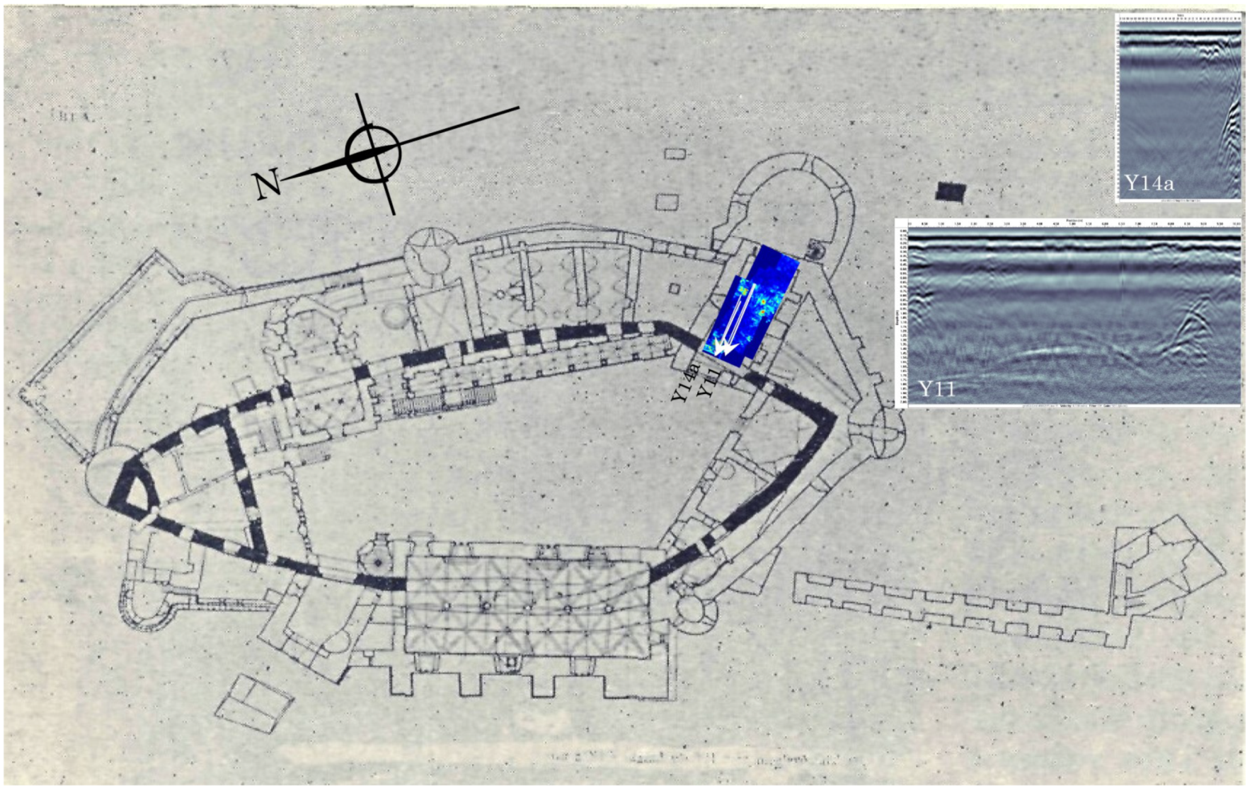
3.8.1. Well Courtyard
In this smaller courtyard, the wall foundation running East to West is the most significant feature, appearing directly south of the well near the center of the y-lines. The related foundations along the eastern side of this earlier room (which used to surround the tower) are also apparent in the GPR results. Also visible in the lines are the modern drainage modifications and the underlying foundations, which are likely shallow constructions on top of the bedrock slope in this area. There are no reflections from remains of the staircase or foundations on the southern side of the Möller and Viennese plans (Figure 31), though remains of the stairs are visible on the exterior of the South wall of the courtyard.
3.8.2. Bear Pit
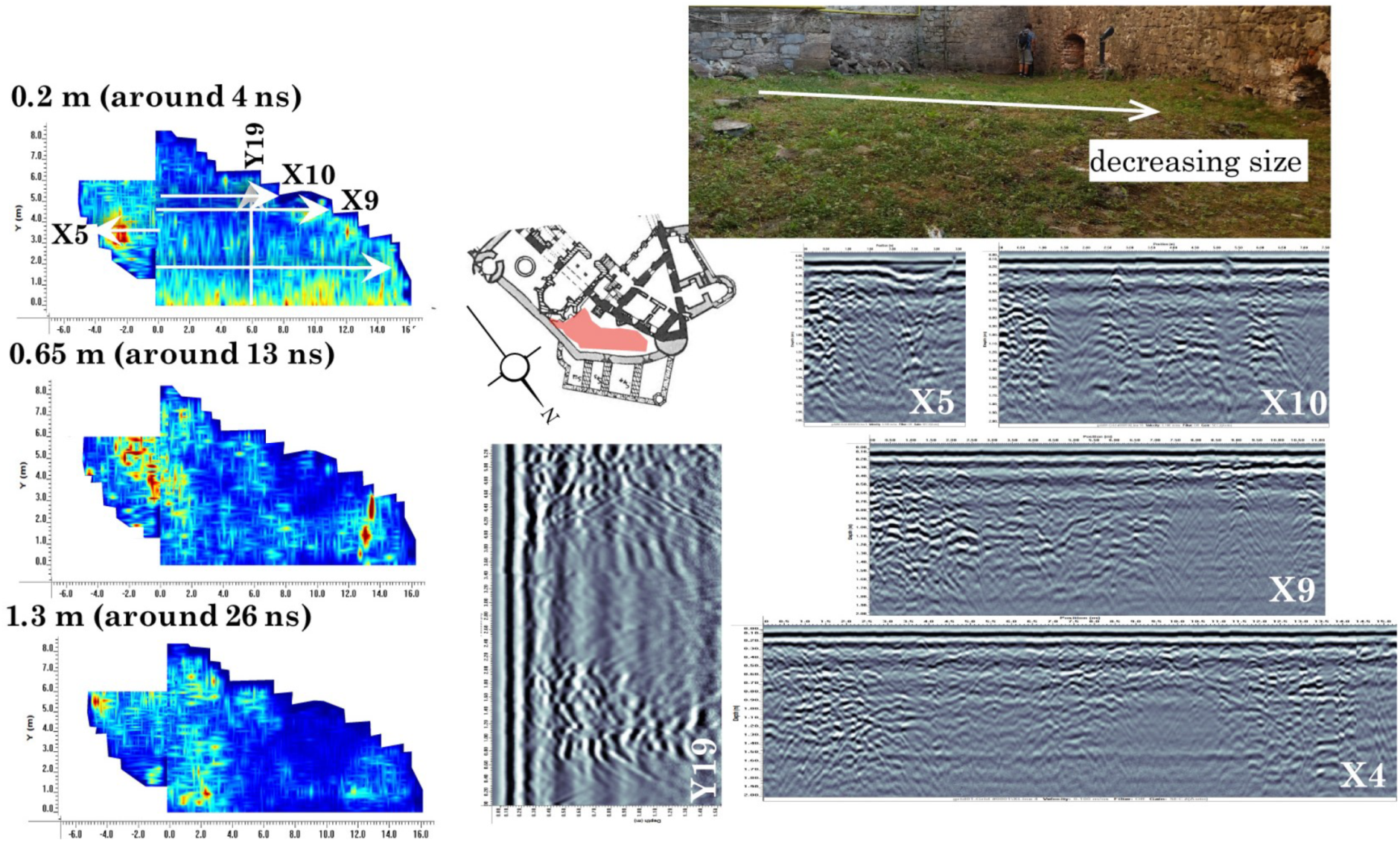
In the Bear Pit, the irregular ground surface and prevailing rubble produce scans which are more difficult to interpret. Numerous surface features can be identified and confirmed on site, including areas of buried rubble surrounding visible piles of debris (especially around the chapel e.g., end of Y19, beginning of X10 and X9, and X5, Figure 32), and the relatively flat and silty accumulation in the northern half of the grid (end of X4). The distribution of debris reflects general principles of erosion, where the larger materials remain higher up on the slope (in the south and west of the grid).
3.8.3. Selected Walls
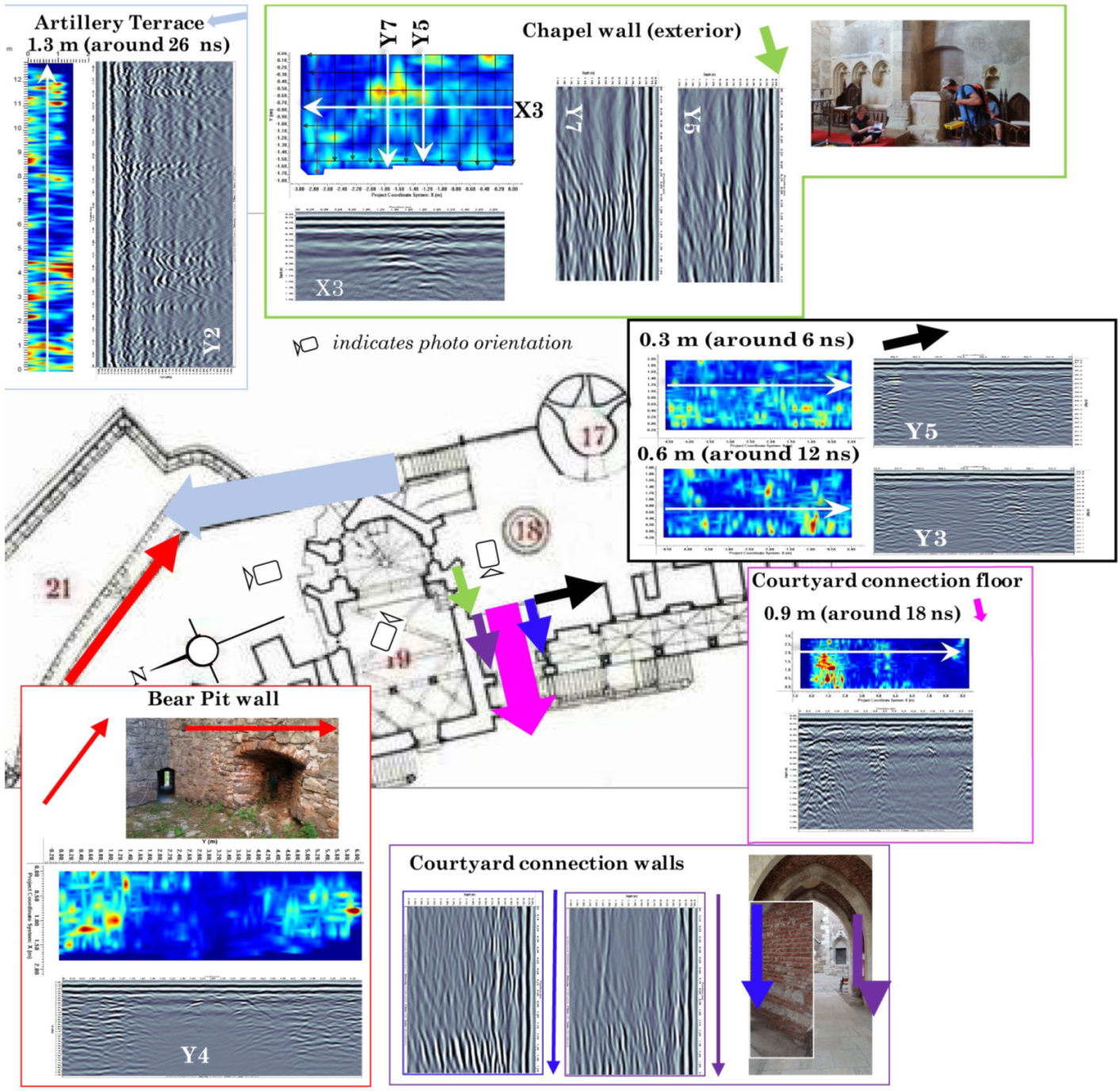
A number of wall sections and related smaller areas of the grounds were scanned, primarily in the eastern portion of the castle (including the Well Courtyard, Bear Pit, and chapel). The primary results of these scans are the presence and location of embedded elements such as portions of older phase walls. First, the outer wall of the Artillery Terrace can be seen inside the wall separating the terrace from the Bear Pit (Figure 33, esp. “Artillery Terrace”). This confirms that the dividing wall is more recent than the Artillery Terrace wall; note that this survey was only collected in on direction. Next, the wall dividing the Bear Pit from the Artillery Terrace, which has a brick archway through the base that runs all the way to the Artillery Terrace, appears to be constructed with two phases. One phase cuts through a vertical section of the wall just above this arch (pictured) and separates the left and right sides of the wall (Figure 33, “Bear Pit wall”). Moving to the connection path between the main courtyard and the Well Courtyard, the walls on each side are constructed of alternating layers of large ashlar masonry and many courses of bricks. In GPR scans, only the lowest layer of stone is easily determined. One possible explanation for this could include the exterior location of these walls and the presence of salts and moisture drawn into the masonry by capillary action (e.g., [34]), which is halted by the change in courses (Figure 33, “courtyard connection walls”). In the floor of this entryway, the abundance of crosscutting wall foundations from earlier phases places the passageway itself most likely in the Bethlen phase (Figure 33, “courtyard connection floor”; also compare to Figure 3). In the courtyard itself, the western wall is reported to contain at least the components of a frame from the original 14th century fortress (Figure 31). GPR scans confirm the embedded brick staircase present in this wall, which is visible in several locations and appears in the lines and depth section (Figure 31) as an area with weaker reflections (Figure 33, right, west wall of courtyard). North of the Well Courtyard, the exterior wall of the chapel contains reflections of the niche and former pulpit are visible (Figure 33, “Chapel wall exterior”).
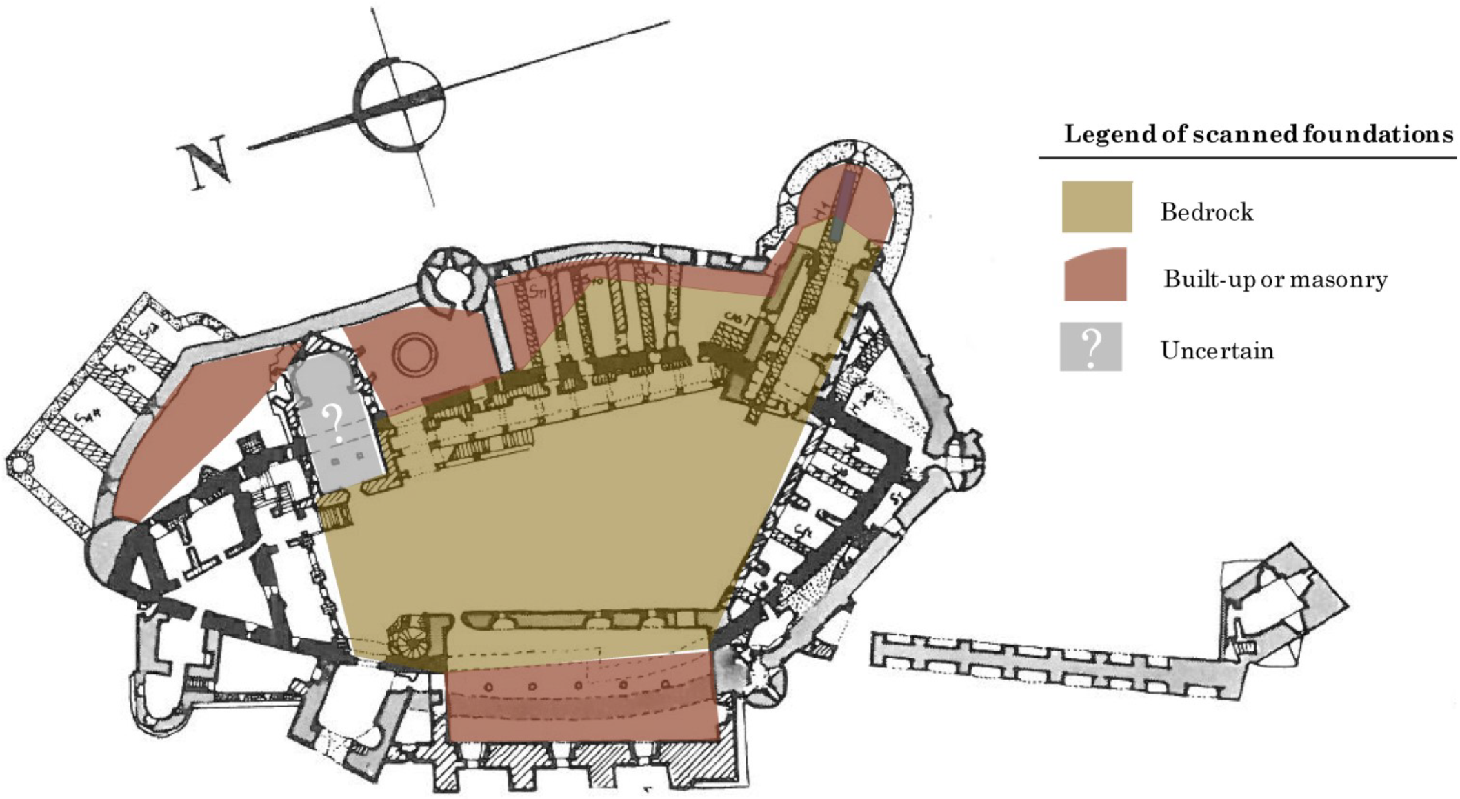
3.9. Foundations
Looking at reflection patterns across scans of the whole castle, the character of the foundations apparently shifts from bedrock to built-up masonry (stone or brick) [30]. In the metamorphic bedrock, there is high attenuation and there are few reflections aside from those of the geological features of the bedrock itself (i.e., metamorphic folds, Figure 23). The built up masonry foundations, on the other hand, can be identified by the abundant reflections from the components of masonry construction. It is proposed that this represents the transition between foundation on bedrock and the foundation laid on top of bedrock using supplemental construction materials (Figure 34). This trend is seen in multiple rooms across the scanned areas of the castle (e.g., Figure 18, Figure 29, and Figure 30). As the castle evolved and its floor plan was expanded, it outgrew the rocky outcrop that served as the primary foundation (especially in the center and south). Additional built-up masonry foundations (either of stone, brick, or a combination of materials) served to expand the area enclosed by the castle walls and create the current footprint of the castle. As determined by GPR, the transition follows the general layout of the original 14th century fortress with the exception of the original entrance and White Tower (Figure 34). The original southeastern entrance to this phase of the castle, now enclosed in the White Tower and entrance hall, lies on the sloping bedrock outside the 14th century walls. The distinction between “bedrock” and “masonry” in Figure 34 is shown as a sharp line, though in most areas (except the Knight’s Hall), it is actually a more gradual transition where the built-up foundations increase in depth according to the profile of the rock below to create a level floor. Archaeological excavations of the chapel indicate built-up foundations on bedrock, though the orientation of this transition is unclear in GPR scans. Also note that the depth of the built-up foundations may exceed the penetration depth (especially in the chapel) of the GPR antenna (1.5 m on average).
4. Discussion
Features identified with GPR provide insight into lingering questions and unresolved historical debates about the castle’s past, including the history of the lapidarium area (Figure 30). This room is much lower in elevation than the rest of the castle. An additional hypothesis arising from these investigations is that the lapidarium and adjacent courtyard with the same floor level were part of the pre-Bethlen phase of the castle. Beginning with Bethlen, later modifications may have sought to provide a larger and more even footprint for the structure. The accuracy of earlier plans of Corvin Castle has been substantiated by GPR surveying and analysis. In scans of the northeast portion of the castle (surrounding the Well Courtyard), there are reflections from wall foundations running East–West and North–South (Figure 31). This feature is shown in the Möller map, however no longer present above ground or indicated in other plans. The data attest to the presence of the crypt and the original fortress wall foundation through the chapel, as in some sources (e.g., Möller, Figure 24). The jagged path of a wall running through the Knight’s Hall in Möller’s map, possibly indicating the uncertainty of the 14th century wall, was verified as a continuous and curved foundation in GPR scans without the jog (Figure 29). Further investigations into the substructures and history of these areas of the castle are an excellent candidate for future targeted investigations aimed at resolving these questions and validating the results of this work. These investigations could be performed as part of restoration efforts using a variety of methods, including small targeted excavations, higher frequency GPR survey, or other methods.
5. Conclusions
Even though historical accounts of Corvin Castle are sparse and can be inconsistent or difficult to obtain, GPR scans were able to confirm features reported in both plans and textual sources, especially the foundation of the 14th century fortress walls (e.g., Figure 15, Figure 22, and Figure 24). In addition, GPR expands our knowledge of known features, corrects previous assumptions, and even identifies unreported substructures and architectural features, especially in the White Tower and the chapel (e.g., Figure 18, Figure 19, and Figure 24). The extent of the bedrock foundations and transition to built-up masonry foundations was previously unknown and has been mapped using GPR in the scanned areas (Figure 34). Moisture ingress identified in the Knight’s Hall and the lapidarium can be localized and investigated (Figure 29 and Figure 30). Unidentified anomalies can be sought out and clarified, increasing our knowledge of Corvin Castle and its complex history while preserving the integrity of the site.
GPR surveys help critically evaluate the quality of the information provided by historical documents, reveal previously unrecorded information (such as the locations of some of Bogdan’s backfilled 1969 trenches, Figure 14) and provide clues to the internal architecture of previous phases (as it did in the present Noble’s Man Kitchen [Figure 16], the courtyard [Figure 23] and lapidarium [Figure 30]). The data also serve as a baseline for more detailed study; for this reason, both selected features and typical scans are presented here. At Corvin Castle, where invasive tests have been the primary (if not exclusive) means of investigation for the last two centuries, nondestructive methods like GPR are critical to the survival of this heritage site and our overall understanding of its history. GPR investigations of Corvin Castle will aid the present restoration effort and future efforts by providing important and more complete reference information about architectural features.
Author Contributions
Conceptualization, I.M. and A.G.; Data curation, I.M. and J.C.; Formal analysis, I.M. and J.C.; Funding acquisition, A.G.; Investigation, I.M. and J.C.; Methodology, I.M. and A.G.; Project administration, I.M. and A.G.; Resources, J.C. and A.G.; Software, I.M. and A.G.; Supervision, I.M., A.G. and B.G.; Validation, I.M., J.C. and B.G.; Visualization, I.M. and B.G.; Writing—original draft, I.M. and J.C.; Writing—review and editing, I.M., J.C., A.G. and B.G.
Funding
This research is part of the graduate research of I.M., funded by the NSF GRFP program, Grant No. DGE #1148900.
Acknowledgments
The authors wish to acknowledge the support of James G. Keppeler and Patty Cleary in editing and drafting; the management of Corvin Castle for consulting and coordinating the surveys (Sorin Tincu and Cristian Roman); staff at the libraries and archives who assisted with sources and images, including Arhiva INP (Institutul Naţional al Partimoniului), Fond DMI (Direcţia Monumentele Istorice), Cercetri arheologice 1967) and University of Vienna’s Department of History of Art (Institut für Kuntegeschichte der Universität Wien, Plansammlung); participants in the Summer 2017 Advanced GPR workshop; Kaleigh Kenney for additional images; the MCDR and Hunedoara Heritage offices for serving as liaisons for the work; Victor Charpentier for assistance and planning of figures; and Kaleigh Kenney and JP Chamness for additional data collection.
Conflicts of Interest
The authors declare no conflict of interest. The funders had no role in the design of the study; in the collection, analyses, or interpretation of data; in the writing of the manuscript, or in the decision to publish the results.
References
- Velescu, O. Castelul de la Hunedoara; Editura Meridiane: Monumentele Patriei Noastre: Bucuresti, Romania, 1961. [Google Scholar]
- Bogdan, A. Contributii arheologice la cunoasterea evolutiei castelului corvinestilor de la hunedoara. Bul. Monum. Istor. 1970, 2, 18–25. [Google Scholar]
- Roman, C.C.; Tincu, S. Observations regarding the ecclesiastical complex from Hunedoara—The Corvin’s Castle. Sargetia Acata Musei Devensis 2012, 3, 243–258. [Google Scholar]
- Schilling, R. Historical conclusions about the archaeological excavations at the medieval castle of Hunedoara. Bul. Monum. Istor. 1970, 2, 55. [Google Scholar]
- Romulus, I. Romanian ironships of the 16th to 18th centuries. Steel Times 1999, 227, 392. [Google Scholar]
- Entz, G. Hunedoara Castle. In Oxford Art Online; Oxford University Press: Oxford, UK, 2003. [Google Scholar] [CrossRef]
- Vatasianu, V. Castelul Corvinilor din Hunedoara. Boabe de Grau 1933, 6, 420–431. [Google Scholar]
- Engle, M. The Collection of plans of the department of history of art. In Academic Showcases: The collections at the University of Vienna; Feigl, C., Beuran, D., Eds.; Bohlau Verlag: Vienna, Austria, 2016; pp. 118–120. [Google Scholar]
- Buck, S.L. Shaker Painted Furniture: Provocative Insights into Shaker Paints and Painting Techniques. In Painted Wood: History and Conservation; Dorge, V., Howlett, F.C., Eds.; The Getty Conservation Institute: Williamsburg, VA, USA, 1994; p. 143. [Google Scholar]
- Ramos, L.F.; Miranda, T.; Mishra, M.; Fernandes, F.M.; Manning, E. A Bayesian approach for NDT data fusion: The Saint Torcato church case study. Eng. Struct. 2015, 84, 120–129. [Google Scholar] [CrossRef] [Green Version]
- Binda, L.; Saisi, A.; Tiraboschi, C. Investigation procedures for the diagnosis of historic masonries. Constr. Build. Mater. 2000, 14, 199–233. [Google Scholar] [CrossRef]
- Ranieri, G.; Godio, A.; Loddo, F.; Stocco, S.; Casas, A.; Capizzi, P.; Messina, P.; Orfila, M.; Cau, M.A.; Chávez, M.E. Geophysical prospection of the Roman city of Pollentia, Alcudia (Mallorca, Balearic Islands, Spain). J. Appl. Geophys. 2016, 134, 125–135. [Google Scholar] [CrossRef]
- Annan, A. Ground Penetrating Radar Principles, Procedures, and Applications; Sensors and Software Inc.: Mississauga, ON, Canada, 2003; p. 285. [Google Scholar]
- Goodman, D.; Piro, S. GPR Remote Sensing in Archaeology; Springer: Berlin/Heidelberg, Germany, 2013. [Google Scholar]
- Conyers, L.B.; Goodman, D. Ground Penetrating Radar: An Introduction for Archaeologists; AltaMira: Walnut Creek, CA, USA, 1997; p. 232. [Google Scholar]
- Jol, H.M. (Ed.) Ground Penetrating Radar Theory and Applications; Elsevier Science: Amsterdam, The Netherlands, 2009; p. 544. [Google Scholar]
- Damiata, B.N.; Steinberg, J.M.; Bolender, D.J.; Zoëga, G.; Schoenfelder, J.W. Subsurface imaging a Viking-Age churchyard using GPR with TDR: Direct comparison to the archaeological record from an excavated site in northern Iceland. J. Archaeol. Sci. Rep. 2017, 12, 244–256. [Google Scholar] [CrossRef]
- Castellaro, S.; Imposa, S.; Barone, F.; Chiavetta, F.; Gresta, S.; Mulargia, F. Georadar and passive seismic survey in the Roman Amphitheatre of Catania (Sicily). J. Cult. Heritage 2008, 9, 357–366. [Google Scholar] [CrossRef]
- Perez Gracia, V.; Canas, J.A.; Pujades, l.G.; Clapes, J.; Caselles, O.; Garcia, F.; Osorio, R. GPR survey to confirm the location of ancient structures under the Valencian Cathedral (Spain). J. Appl. Geophys. 2000, 43, 167–174. [Google Scholar] [CrossRef]
- Pérez-Gracia, V.; Caselles, J.O.; Clapés, J.; Martinez, G.; Osorio, R. Non-destructive anlaysis in cultural heritage buildings: Evaluating the Mallorca cathedral supporting structures. NDT E Int. 2013, 59. [Google Scholar] [CrossRef]
- Ferrara, C.; Barone, P.M. Detecting moisture damage in archaeology and cultural heritage sites using the GPR technique: A brief introduction. Int. J. Archaeol. 2015, 3, 57–61. [Google Scholar] [CrossRef]
- Pincus, J.A.; De Smet, T.S.; Tepper, Y.; Adams, M.J. Ground-penetrating radar and electromagnetic archaeogeophysical investigations at the Roman legionary Camp at Legio, Israel. Archaeol. Prospect. 2013, 20, 175–188. [Google Scholar] [CrossRef]
- Conyers, L.B. Ground-penetrating radar mapping using multiple processing and interpretation methods. Remote Sens. 2016, 8, 562. [Google Scholar] [CrossRef]
- Ercoli, M.; Brigante, R.; Radicioni, F.; Pauselli, C.; Mazzocca, M.; Centi, G.; Stoppini, A. Inside the polygonal walls of Amelia (Central Italy): A multidisciplinary data integration, encompassing geodetic monitoring and geophysical prospections. J. Appl. Geophys. 2016, 127, 31–44. [Google Scholar] [CrossRef]
- Roman, C.C.; Tincu, S. Observatii pe marginea complexului ecleziastic de la Hunedoara—Castelul Corvinilor. Terra Sebus 2009, 1, 153–171. [Google Scholar]
- Pataki, I. Hunedoara Domain at the Beginning of the 16th Century: Study and Documents; Publishing House of the Academy of the Socialist Republic of Romania: Bucharest, Romania, 1973; Volume 39. [Google Scholar]
- Ion, R.M.; Iancu, L.; Carutiu, D.T.; Schroder, V.; Tincu, S.; Roman, C.; Ion, N.; Bucurica, I.A.; Teodorescu, S.; Dulama, I.D.; et al. Traditional building materials and modern restoration products identified at the painted Matia-fresco Loggia, Corvins’ Castle, Romania. In Proceedings of the Geophysical Research Abstracts: EGU General Assembly 2018, Vienna, Austria, 8–13 April 2018; EGU, Ed.; Volume 20, p. 5198. [Google Scholar]
- Ion, R.; Iancu, L.; Grigorescu, R.; Carutiu-Turcanu, D.; Tincu, S.; Ion, N.; Bucurica, I.; Teodorescu, S.; Dulama, I.; Stirbescu, R.; et al. Arhaeometric Concepts and Methods of Intervention on Historical Monument Buildings. The Case of the Corvins’ Castle. In IOP Conference Series: Materials Science and Engineering; IOP Publishing Ltd.: Bristol, UK, 2018; Volume 374. [Google Scholar] [CrossRef]
- Foldvary, G.Z. Geology of the Carpathian Region; World Scientific: Hackensack, NJ, USA, 1988. [Google Scholar]
- Morris, I.M.; Cleary, J.; Keppeler, J.G.; Gonciar, A.; Glisic, B. Confirming archaeological excavation results with ground penetrating radar: The main courtyard of Corvin Castle. In Proceedings of the AGU Fall Meeting, Washington, DC, USA, 10–14 December 2018. [Google Scholar]
- Roman, C.C.; Diaconescu, D.; Tiplic, M. Archaeological excavations at Hunedoara—The Corvins’ Castle—The sacristy of the chapel. In Studii de Istorie Veche si Arheologie: Bibliotheca Archaeologica et Historica Corvinensis—IV; Matos, C., Ed.; Editura Mereamia Napocae: Hunedoara, Romania, 2004. [Google Scholar]
- Filitti, G. Călători străini despre Ţările Române în secolul al XIX-lea; Number 2; Editura Academiei Române: Bucurest, Romania, 2005. [Google Scholar]
- Gonciar, A.; Roman, C.C.; Hunedoara, Romania. Personal Communication, 2017.
- Doehne, E.; Price, C.A. Stone Conservation: An Overview of Current Research, 2nd ed.; Getty Conservation Institute: Los Angeles, CA, USA, 2011; Volume 2, p. 164. [Google Scholar] [CrossRef]
| 1. | Though Möller initially dated the first fortress to the late 13th century based on the composition of the mortar, historians throughout the 20th century generally agree that the fortress was more likely built sometime in the mid- to late-14th century. Roland Schilling makes a compelling argument for the first documentation of the fortress in the year AD 1364 as noted at the end of Bogdan’s German summary [2]. |
| 2. | Bogdan [2] elaborates that a campaign from 1966 to 1969 carried out “by the Historical Monuments Directorate of C.S.C.A. (Chief Project Officer E. Chefneux)” engaged in several restoration projects involving the Bethlen wing, the Zolyomi (South) wing, Diet Hall, the Matthaias Corvin wing and the Bethlen terrace. |
| 3. | The data is available by request from the authors (Andre Gonciar or Isabel Morris). |
| 4. | All three of these sources were translated from their original Romanian. The authors apologize if any information was lost or mistaken during translation. |
| 5. | Including, for example, Valentin Török reportedly beheading his adulterous wife Barbara in the courtyard in 1557 [1]. |
| 6. | The cell is incorrectly rumored to have briefly imprisoned Vlad the Impaler, but there is no evidence for this. |
| 7. | The well in the courtyard is sometimes called the “Turkish Well” because it was dug by Turkish prisoners during the 15th century. According to legend, the prisoners were promised their freedom in exchange for reaching water, but perhaps never freed upon completion of the well [1]. |
| 8. | Möller’s plans are based on his excavation and Aranyi’s drawings, and since his publication in the early 20th century historians have pondered the possibility of a tower structure in the NE corner of the original fortress not reflected in Möller’s plans. Historical documents and published stratigraphy neither confirm nor deny existence of this 14th century tower structure in the NE of Corvin’s Castle. |
Figure 1.
Corvin Castle as seen from the modern entrance gate.

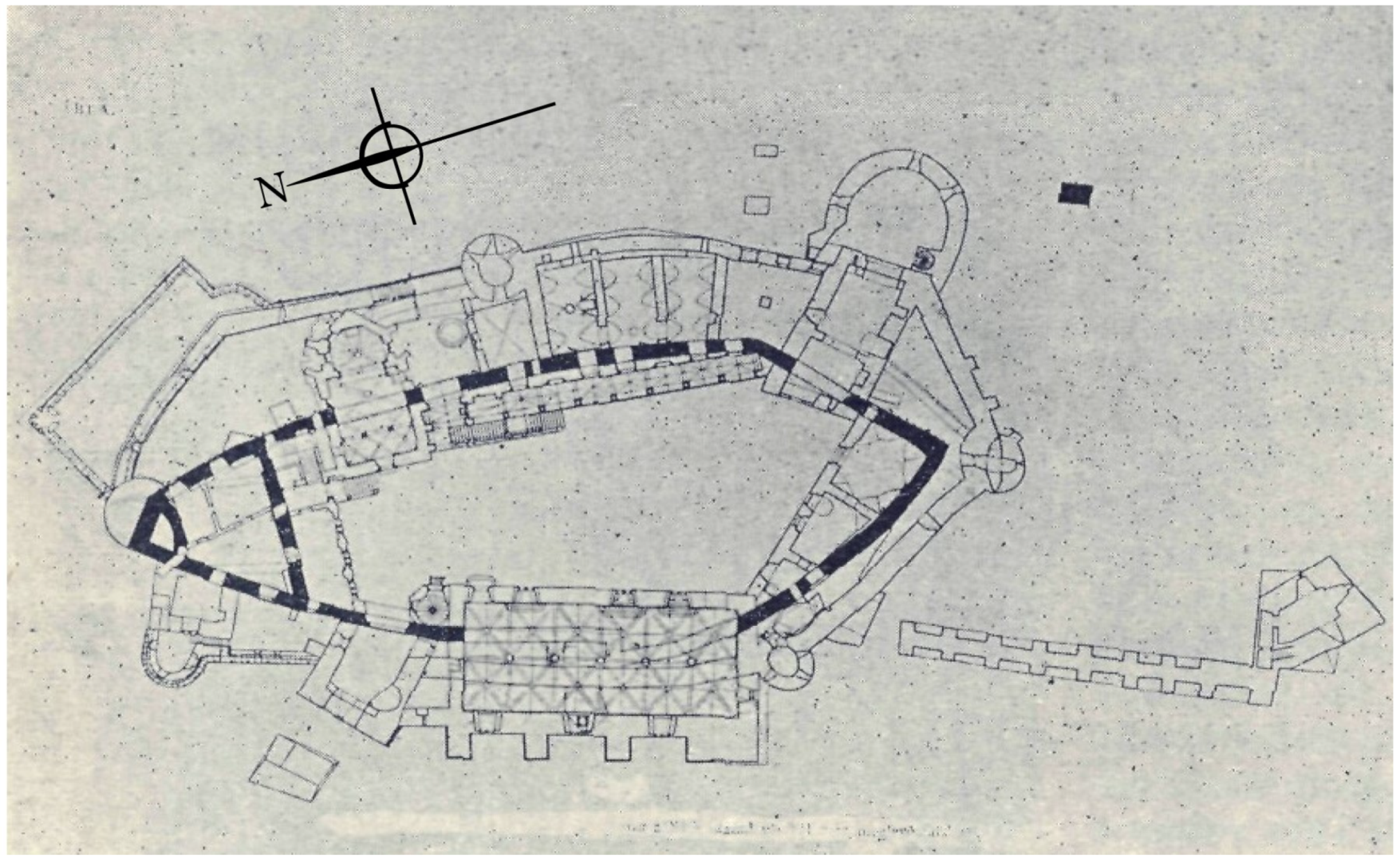
Figure 2.
A sketch of Corvin Castle phases drawn by Möller during his 1907–1914 investigation. The original oval fortress is drawn with bold black lines. Möller had thought the first structure was established at the end of the 13th century, though modern historians believe the fortress began in the middle of the 14th century [7].

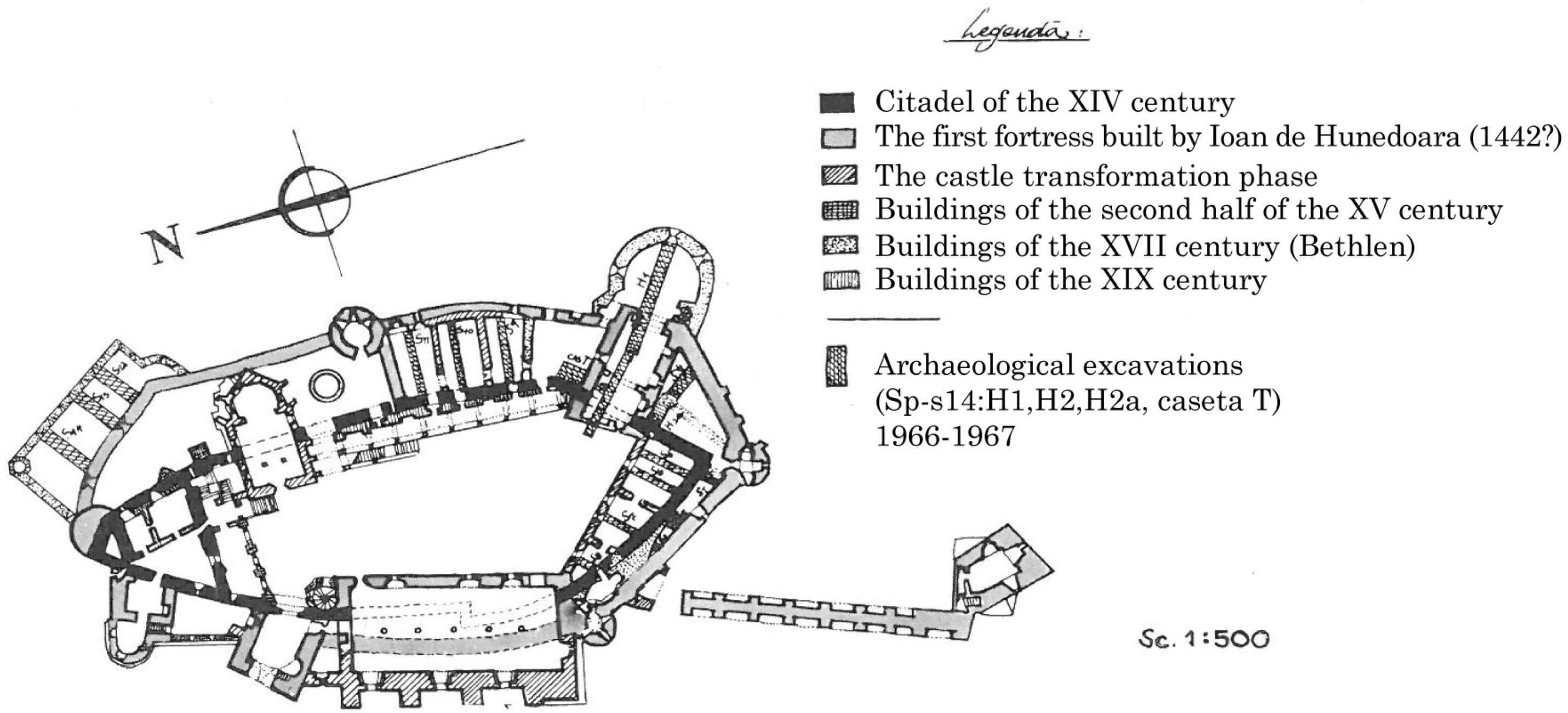
Figure 3.
Bogdan’s map of construction phases and excavations, translated and used with permission of Arhiva INP (Figure 2, [2]).
Figure 3.
Bogdan’s map of construction phases and excavations, translated and used with permission of Arhiva INP (Figure 2, [2]).

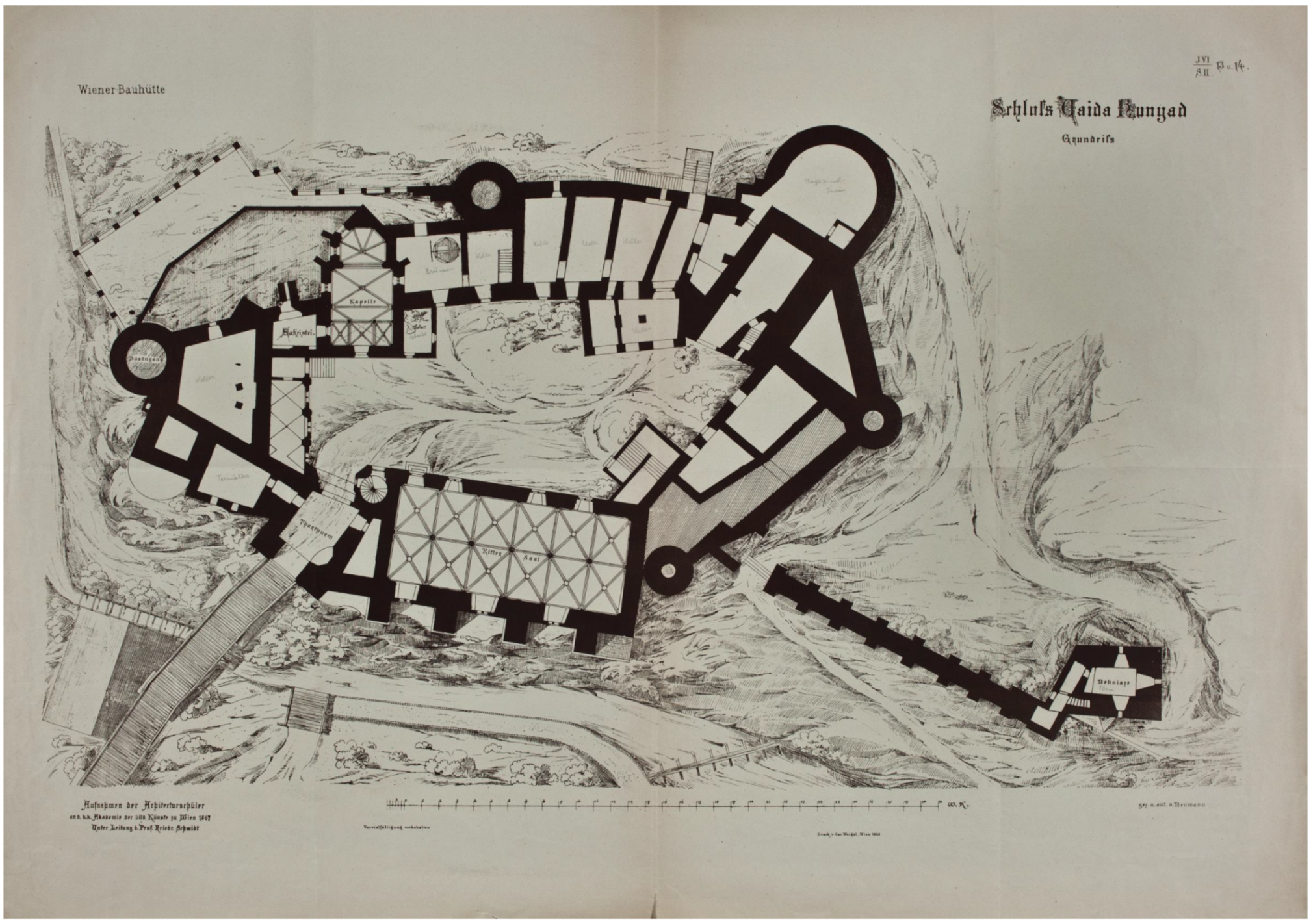
Figure 4.
Ground plan of Corvin Castle by Franz Neumann, Publicationen der Wiener Bauhutte, Jg. Vl.2, Blatt 13-14, used with permission from Institut für Kunstgeschichte der Universität Wien, Plansammlung [8].
Figure 4.
Ground plan of Corvin Castle by Franz Neumann, Publicationen der Wiener Bauhutte, Jg. Vl.2, Blatt 13-14, used with permission from Institut für Kunstgeschichte der Universität Wien, Plansammlung [8].

Figure 5.
Summary of scanned areas of the castle (based on Figure 3).
Figure 5.
Summary of scanned areas of the castle (based on Figure 3).

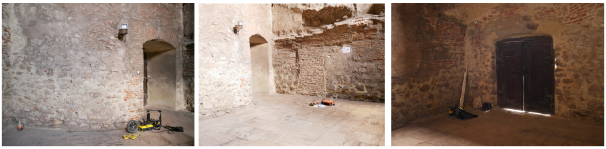
Figure 6.
GPR scanning in the Noble’s Man Kitchen, facing eastern exterior wall.

Figure 7.
Images taken from the White Tower (left) and entrance hall facing the tower (right).

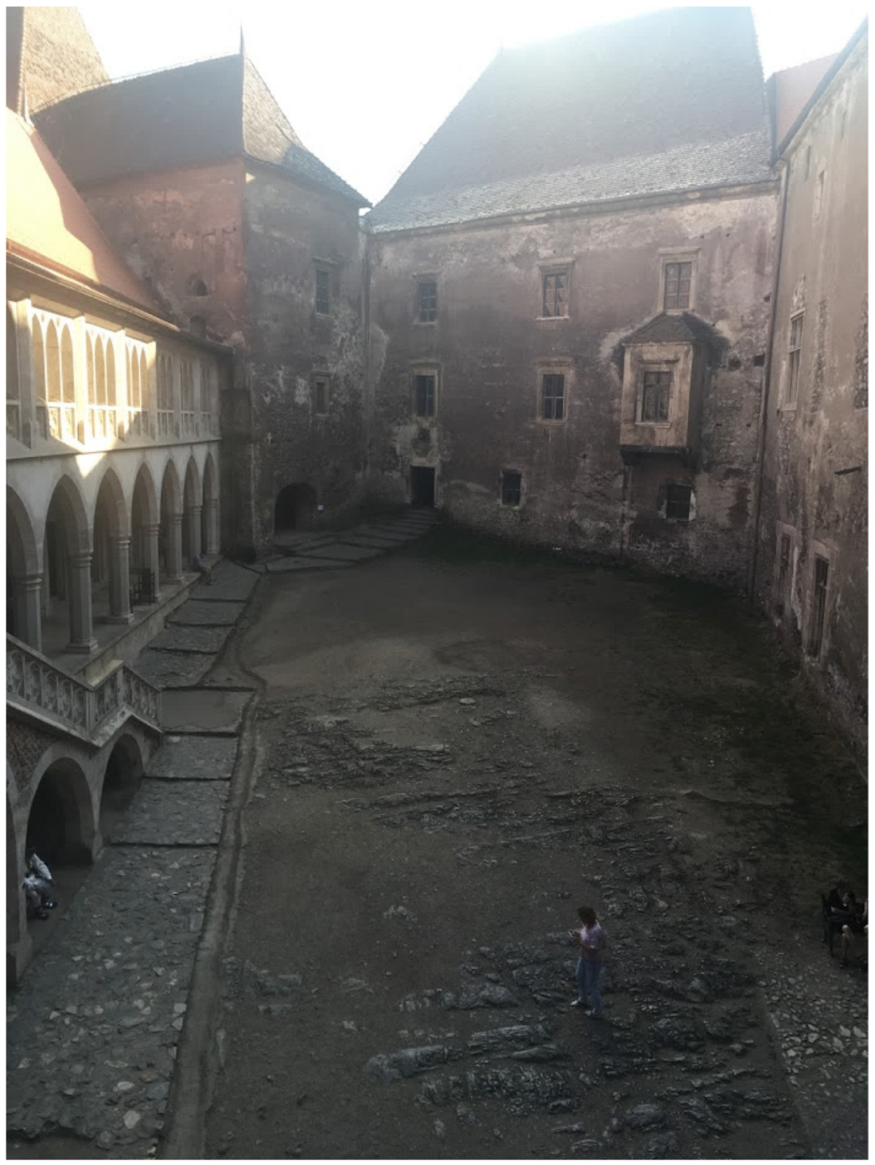
Figure 8.
Image of courtyard taken from the balcony of the Bethlen wing.

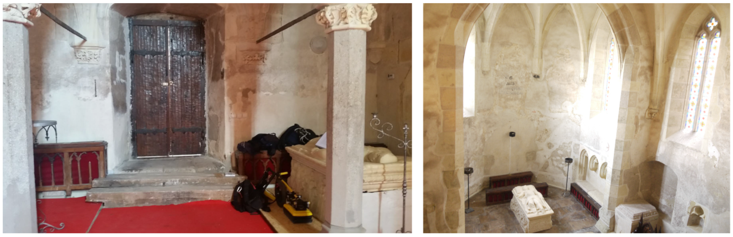
Figure 9.
GPR scanning in the chapel, facing east towards the apse.


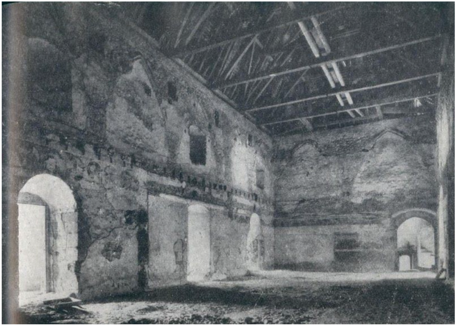
Figure 11.
Velescu’s image of the Diet Hall as it looked before restoration, used with permission ([1], Arhiva INP).
Figure 11.
Velescu’s image of the Diet Hall as it looked before restoration, used with permission ([1], Arhiva INP).

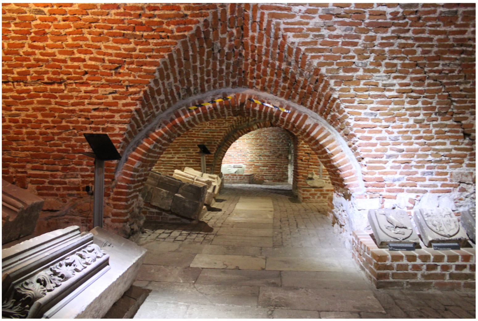
Figure 12.
Image of the modern lapidarium.

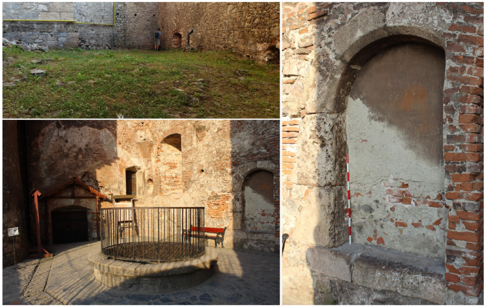
Figure 13.
Features in the northeast sector, including the Bear Pit and the repurposed frame and embedded staircase in the Well Courtyard.
Figure 13.
Features in the northeast sector, including the Bear Pit and the repurposed frame and embedded staircase in the Well Courtyard.

Figure 14.
Depth slices of the Noble’s Man Kitchen showing the excavation backfill in the lower right-hand corner, the exterior wall across the top, and the variable depth of the backfilled trench(es) in lines X3 and X7.
Figure 14.
Depth slices of the Noble’s Man Kitchen showing the excavation backfill in the lower right-hand corner, the exterior wall across the top, and the variable depth of the backfilled trench(es) in lines X3 and X7.

Figure 15.
Deeper slice showing possible wall foundations along the exterior wall and near the 14th century fortress present in the kitchen.
Figure 15.
Deeper slice showing possible wall foundations along the exterior wall and near the 14th century fortress present in the kitchen.

Figure 16.
GPR lines and photograph of the 1cm thick northern wall in the kitchen with different phases and wall treatments on the surface. Note the supporting elements indicated on the western (left) side.
Figure 16.
GPR lines and photograph of the 1cm thick northern wall in the kitchen with different phases and wall treatments on the surface. Note the supporting elements indicated on the western (left) side.

Figure 17.
Bogdan’s reported profiles (with author translations) from the white tower and entrance hall. H1 is in the tower (east), H2 is in the entrance hall (west) (figure from Bogdan (1970, [2] used with permission).
Figure 17.
Bogdan’s reported profiles (with author translations) from the white tower and entrance hall. H1 is in the tower (east), H2 is in the entrance hall (west) (figure from Bogdan (1970, [2] used with permission).

Figure 18.
Depth slice at 0.8 m (16 ns) and radargrams showing the transition from bedrock foundation to built up masonry foundations in the White Tower. Note the location of the backfilled trench H1 through the center, where the foundation is homogeneous and modern. Note that the lines presented belong to two grids but are oriented in the tower as shown.

Figure 19.
Shallow depth slice of tower at 55 cm (11 ns), showing feature in the central southeast half of the tower.
Figure 19.
Shallow depth slice of tower at 55 cm (11 ns), showing feature in the central southeast half of the tower.

Figure 20.
0.8 m depth slice showing the cross cutting of two walls (upper half, 0.8 m) and the dipping reflector from the other figure (lower half, 0.8 m). 1.55 m depth slice and lines show the bottom of the backfilled trench H2, also shown in two representative lines (X11 and X20). NB: contrast slightly enhanced in these slices.

Figure 21.
Radargrams showing the dipping reflector across the center of the room, possibly in line with the dotted wall noted in Bogdan’s map and an earlier boundary. Also notice the wall foundation which appears in lines in G2 and which may correspond to the original stone fortress shown in solid black on the Bogdan and Möller maps.

Figure 22.
Possible identification of original 14th century fortress under the courtyard side of the entrance hall (shown on the right-hand side of each line) with the Möller map [7].
Figure 22.
Possible identification of original 14th century fortress under the courtyard side of the entrance hall (shown on the right-hand side of each line) with the Möller map [7].

Figure 23.
Depth slices and radargrams from the courtyard scans. Lines X23 and X24 show the two wall foundations (on the left); In X23, X24, and Y30, note the upward sloping reflections from underlying geology. Line Y8 is typical of the southern (left) half of the courtyard, with both geological and anthropogenic features.

Figure 24.
GPR scans of the crypt showing depth slices of the upper portion (0.4 m) and the floor (starting at 1.25 m). Note the change in fill from east to west visible in line Y8 and near X8 that likely indicates the inclusion of the 14th century fortress wall.
Figure 24.
GPR scans of the crypt showing depth slices of the upper portion (0.4 m) and the floor (starting at 1.25 m). Note the change in fill from east to west visible in line Y8 and near X8 that likely indicates the inclusion of the 14th century fortress wall.

Figure 25.
Lines investigating features on the southern side of the chapel. In the slice at 1.5 m, it is clear that there are two separate features, likely early wall foundations. The upper foundation (in lines X12 and X14) may be part of the original 14th century fortress, which ran through the center of the chapel from North to South according to the Bogdan and Möller maps.

Figure 26.
Lines in the apse showing foundations of walls or courtyards on the chapel’s exterior, as indicated by Möller and Neumann’s plan; this detail is omitted from Bogdan’s map. In Y8, note the abrupt surface change from the carpet across the front of the apse (also visible in the depth slice).

Figure 27.
Representative radargrams of the Neboisa tower and gallery; note the arch reflections in the edges of the gallery (Y0), also visible in the first half of X1.
Figure 27.
Representative radargrams of the Neboisa tower and gallery; note the arch reflections in the edges of the gallery (Y0), also visible in the first half of X1.

Figure 28.
Depth slices and radargrams showing different aspects of the Knight’s Hall vaulted ceiling from the floor in the Diet Hall above. Notice the curvature of the vaults in line Y11 and the rib visible in line X59.
Figure 28.
Depth slices and radargrams showing different aspects of the Knight’s Hall vaulted ceiling from the floor in the Diet Hall above. Notice the curvature of the vaults in line Y11 and the rib visible in line X59.

Figure 29.
GPR results from the Knight’s Hall. The interpreted features are included in the map, shown in the depth slice, and also visible in the linescans.
Figure 29.
GPR results from the Knight’s Hall. The interpreted features are included in the map, shown in the depth slice, and also visible in the linescans.

Figure 30.
GPR results from the Lapidarium showing the variety of features. In the Y lines, notice the built-up foundations at the north end and the deep feature in the center; in X10, note the deep feature at the beginning of the scan; in X3, the bedrock to masonry foundation at the end of the line; the possible trench floor in Y4G3*; the built up foundations and high humidity in Y3 G4*.

Figure 31.
In the eastern courtyard with the well, the most significant feature found with the GPR is the wall foundation running east–west (near the center of Y1). This is the outer wall of an earlier room (shown in the inset) which appears on some maps of castle (such as Figure 2 and Figure 4).

Figure 32.
Selected lines and depth slices from the Bear Pit. Note the rubble piles on the southern edge (and in X5) and the predominant areas of high scatter vs. low scatter.
Figure 32.
Selected lines and depth slices from the Bear Pit. Note the rubble piles on the southern edge (and in X5) and the predominant areas of high scatter vs. low scatter.

Figure 33.
GPR scans and results from the northeast sector.

Figure 34.
Compilation of scanned and identified foundations. The foundation composition in the chapel is still unknown, but likely contains both built-up and bedrock foundations. Note the unscanned areas and comparison to the solid black 14th century extent walls, overlain on map from Bogdan (1970, [2].)

© 2019 by the authors. Licensee MDPI, Basel, Switzerland. This article is an open access article distributed under the terms and conditions of the Creative Commons Attribution (CC BY) license (http://creativecommons.org/licenses/by/4.0/).
Share and Cite
MDPI and ACS Style
Morris, I.; Cleary, J.; Gonciar, A.; Glisic, B. Ground Penetrating Radar Investigation of Corvin Castle (Castelul Corvinilor), Hunedoara, Romania. Heritage 2019, 2, 1316-1349. https://0-doi-org.brum.beds.ac.uk/10.3390/heritage2020085
AMA Style
Morris I, Cleary J, Gonciar A, Glisic B. Ground Penetrating Radar Investigation of Corvin Castle (Castelul Corvinilor), Hunedoara, Romania. Heritage. 2019; 2(2):1316-1349. https://0-doi-org.brum.beds.ac.uk/10.3390/heritage2020085
Chicago/Turabian StyleMorris, Isabel, Julia Cleary, Andre Gonciar, and Branko Glisic. 2019. "Ground Penetrating Radar Investigation of Corvin Castle (Castelul Corvinilor), Hunedoara, Romania" Heritage 2, no. 2: 1316-1349. https://0-doi-org.brum.beds.ac.uk/10.3390/heritage2020085