Review

Corrosion of Carbon Steel in Marine Environments: Role of the Corrosion Product Layer

1
Laboratoire des Sciences de l’Ingénieur pour l’Environnement (LaSIE), UMR 7356 CNRS-La Rochelle Université, Av. Michel Crépeau, CEDEX 01, F-17042 La Rochelle, France
2
Naval Group Research, BP 440, CEDEX 50104 Cherbourg-Octeville, France
*
Author to whom correspondence should be addressed.
Corros. Mater. Degrad. 2020, 1(1), 198-218; https://0-doi-org.brum.beds.ac.uk/10.3390/cmd1010010
Submission received: 5 May 2020 / Revised: 29 May 2020 / Accepted: 30 May 2020 / Published: 3 June 2020

Abstract

:
This article presents a synthesis of recent studies focused on the corrosion product layers forming on carbon steel in natural seawater and the link between the composition of these layers and the corrosion mechanisms. Additional new experimental results are also presented to enlighten some important points. First, the composition and stratification of the layers produced by uniform corrosion are described. A focus is made on the mechanism of formation of the sulfate green rust because this compound is the first solid phase to precipitate from the dissolved species produced by the corrosion of the steel surface. Secondly, localized corrosion processes are discussed. In any case, they involve galvanic couplings between anodic and cathodic zones of the metal surface and are often associated with heterogeneous corrosion product layers. The variations of the composition of these layers with the anodic/cathodic character of the underlying metal surface, and in particular the changes in magnetite content, are thoroughly described and analyzed to enlighten the self-sustaining ability of the process. Finally, corrosion product layers formed on permanently immersed steel surfaces were exposed to air. Their drying and oxidation induced the formation of akaganeite, a common product of marine atmospheric corrosion that was, however, not detected on the steel surface after the permanent immersion period.

1. Introduction

Seawater is one of the most complex and aggressive media. Marine corrosion depends on numerous interdependent parameters and combines chemical, biological and mechanical factors. The understanding of the influence of each of these parameters and factors is the key to the optimization of the design of metal structures and devices used in marine environments. It is also the key to the optimization of anticorrosion methods and materials performance. Localized corrosion is a particularly insidious degradation phenomenon and thus a hazard for metal structures integrity. Severe localized degradations may induce major industrial failures while consuming a very small amount of materials. In seawater, owing to various combined factors such as materials heterogeneity (grain boundaries, inclusions, welds…) [1,2,3,4,5], differential aeration [6,7,8,9], and biological activity [10,11,12,13,14,15,16,17,18], the corrosion processes of carbon steels, though commonly acknowledged as being mainly uniform, are often localized. The well-known ALWC (Accelerated Low Water Corrosion) phenomenon, which combines differential aeration and bacteria consortium activity [15,17], perfectly illustrates this point.
Carbon steels are widely used materials for marine applications. They are massively produced (~1.8 × 10⁹ tons worldwide in 2018 [19]) and are actually inexpensive while they offer good mechanical properties. They also mainly suffer uniform corrosion and were studied for decades so that their corrosion rate can be modeled and their lifetime predicted with rather good accuracy in various marine environments. The phenomenological model proposed by Melchers et al. [20,21,22] was designed via a thorough analysis of numerous data. It is based on the description and understanding of the mechanisms of the uniform corrosion process of iron-based materials. It aims to predict the short and long-term behavior of steel structures permanently immersed in seawater and forecast reliably the lifetime of these structures.
Microbiologically influenced corrosion (MIC) is often considered the main reason for the non-uniformity of carbon steel corrosion in seawater [10,11,12,13,14,15,16,17,18]. The biofilm that forms on any material immersed in seawater is intrinsically heterogeneous and leads to the coexistence of aerated and deaerated zones, creating aeration cells and favoring the growth and activity of harmful microorganisms. Electroactive bacteria may even uptake electrons from the metal and thus influence directly the corrosion rate [23,24,25]. However, if sulfate-reducing bacteria (SRB) develop initially in deaerated zones because they are anaerobe microorganisms and favor temporarily localized corrosion processes, they rapidly colonize the whole metal surface [26], which ultimately leads again to more or less uniform corrosion [22,26].
The solid corrosion products forming on the steel surface are the primary consequences of the dissolution of the metal. They can strongly affect the ongoing corrosion process. First of all, they form a physical barrier between metal and environment and therefore contribute to the protection of the metal, because they hinder the transport of dissolved oxygen from seawater to the metal surface [20,21]. Secondly, they are porous and thus offer a unique habitat for microorganisms that can develop in a specific environment [26,27,28,29,30,31]. Thirdly, some phases are electronic conductors, e.g., magnetite [32,33,34] and iron sulfides [16,23], which can favor galvanic cells. The composition of the corrosion product layer also varies with the exposure zone [26,35,36,37,38,39,40,41,42] and may change in the long term [43].
This article reports recent advances in the understanding of localized corrosion processes of carbon steel permanently immersed in natural seawater, obtained through a detailed analysis of the corrosion product layers [26,30,36,41,42,44]. These layers, formed on steel surfaces in laboratory experiments or seaport exposure sites, reflect the complexity of iron chemistry in natural seawater. Their composition differs in anodic and cathodic zones [9,41,42] so that they participate actively in the persistence of corrosion cells and favor localized corrosion processes [41].

2. Materials and Methods

2.1. Materials and Exposure Sites

The article is focused on results obtained with natural seawater. Actually, the complex mechanisms involved during marine corrosion cannot be fully reproduced via laboratory experiments using artificial seawater.
The results discussed here were obtained with coupons immersed in three main exposure sites. Two of these sites were set in seaports of La Rochelle (Atlantic Ocean, France). In one site (Les Minimes marina), the coupons were immersed at constant immersion depth (~50 cm). In the other site (cargo port), the immersion depth, i.e., the distance between coupon and atmosphere, varied with the tide, between a few centimeters and ~5 m. The third site was the Naval Group Research laboratory in Cherbourg (English Channel, France). In this facility, natural seawater is pumped directly from the English Channel to flow continuously at a rate of 100 L/h through the electrochemical cells. In this last case, the steel coupons were 5–10 cm distant from the seawater/air interface so that differential aeration phenomena could be induced and favored localized corrosion. However, the results obtained in each site proved comparable so that general trends could be deduced. More detailed information on the exposure conditions can be found in the original articles [26,30,36,37,40,41,42,43,44].
It is also worthy to recall the average composition of seawater. The study of the water flowing through the Naval Group Research lab in Cherbourg led to the following composition (main ionic species only): [Cl] = 19 g kg−1, [SO42−] = 2.7 g kg−1, [HCO3] = 0.14 g kg−1, [Na+] = 10 g kg−1, [Mg2+] = 1.3 g kg−1, [Ca2+] = 0.41 g kg−1 and [K+] = 0.4 g kg−1. It clearly shows that seawater is not, in any case, a simple NaCl solution, and the role of various other species, e.g., SO42−, Ca2+, Mg2+, and HCO3, is clearly illustrated by the composition of the mineral layers covering carbon steel in seawater [26,30,36,41,42]. Note also that the alkalinity of seawater (pH measured between 8.0 and 8.2 at Naval Group Research lab), is mainly associated with the presence of hydrogencarbonate ions.
The present article describes the behavior of carbon steel and thus does not deal with the influence of alloying elements. More precisely, the article relates to studies performed with three main materials. The first one is the alloy typical of sea harbor steel sheet piles, i.e., carbon steel S355GP. The other alloys are S355NL and TU250B carbon steels. The composition of each steel grade is given in Table 1. The slight observed differences, e.g., less carbon and manganese and more copper for TU250B, did not lead to detectable effects [41] so that it can be considered that the composition of the corrosion product layer does not depend, or only marginally, on the considered carbon steel grade. This is also illustrated by the results obtained with different carbon steel alloys [26,30,36,41,42]. Experimental details about the preparation of the carbon steel samples can be found in the original articles [26,30,36,37,40,41,42,43,44]. In any case, the steel surface was shot blasted to remove any trace of previous rusting or mill scale and degreased with acetone.

2.2. Characterization of the Corrosion Product Layers

The characterization of the corrosion product layers requires that samples are preserved from oxidation by air (or more exactly oxygen). This important point is developed in the article (Section 5). In the lab, the samples can be kept in a freezer (−24b °C), a simple procedure that hinders the oxidation of Fe(II)-based corrosion products that are reactive towards oxygen [40,41,42]. This frozen state moreover facilitates the sampling of small slices of corrosion product layers that can be easily handled. Once warmed up, these solid slices transform to sludge due to their high content of water.
The thorough and unambiguous characterization of the phases present in the corrosion product layers cannot be achieved using a single analytical tool. Moreover, the characterization techniques must be adapted to the particular nature of the layers that are thick, heterogeneous, and very porous. The pores are filled with water, microorganisms, and organic matter. When analyzing a corrosion product layer, the first objective is to identify all the crystalline solid phases that constitute this layer. This can be achieved using X-ray diffraction (XRD). Another technique must at least be used to characterize amorphous, nanocrystalline or poorly crystallized compounds. The second objective is to determine how the various compounds are distributed inside the corrosion product layer, in particular, to establish if there exists some kind of stratification from metal to seawater. A local method such as µ-Raman spectroscopy (µ-RS) is adequate for that purpose. µ-RS is moreover suitable for the analysis of wet (and even immersed) samples and the characterization of non-crystalline matter. The combination of µ-RS with XRD, used in various works [26,30,36,37,39,40,41,42,43,44], is then a minimal requirement.
µ-RS analysis was performed in any case at room temperature using a Jobin Yvon High Resolution Raman spectrometer (LabRam HR or LabRam HR evo) equipped with a confocal microscope and a Peltier-based cooled charge-coupled device (CCD) detector. Two laser sources were used indifferently, a solid-state diode-pumped green laser (532 nm) or a He-Ne laser (632.8 nm). The laser power must be reduced down to 10% (0.6 mW), and in some cases, even to 1% (0.06 mW), of the maximum to prevent the transformation of the analyzed compounds into hematite α-Fe2O3. This transformation can take place due to excessive heating, as observed for Fe(III)-oxyhydroxides [45] and magnetite Fe3O4 [45,46]. The acquisition time was variable and depended on the nature of the analyzed phase. It was generally equal to 60 s but could be increased up to 2 min to optimize the signal to noise ratio. At least 20 zones (diameter of 3–6 μm) of a given sample were analyzed through a 50× long working distance objective (50 × LWD). A motorized XY stage was used in order to focus on the different zones of the sample and determine the possible organization/stratification of the corrosion product layer. Most of the investigations could be performed without specific protection from air, which was possible because the time required for analysis was short and samples remained wet during analysis, which delays oxidation.
X-ray diffraction (XRD) analysis was performed with an Inel EQUINOX 6000 diffractometer, using a curved detector (CPS 590), with the Co-Kα radiation (λ = 0.17903 nm) at 40 kV and 40 mA. The CPS 590 detector is designed for the simultaneous detection of the diffracted photons on a 2θ range of 90°. The analysis was performed with a constant angle of incidence (5 degrees) for 30 to 60 min depending on the sample. To prevent the oxidation of Fe(II)-based compounds during preparation and analysis, the samples were mixed with a few drops of glycerol in a mortar before being crushed until a homogenous oily paste was obtained. With this procedure, the various particles that constitute the sample are coated with glycerol and thus sheltered from the oxidizing action of O2 [47]. Glycerol may only give rise to a very broad “hump” visible on the XRD pattern between 2θ~25° and 2θ~35° [48].
XRD and µ-RS results are displayed throughout the present article to illustrate the complexity of the corrosion product layers formed on carbon steel in natural seawater.

3. General Features of the Corrosion Product Layer

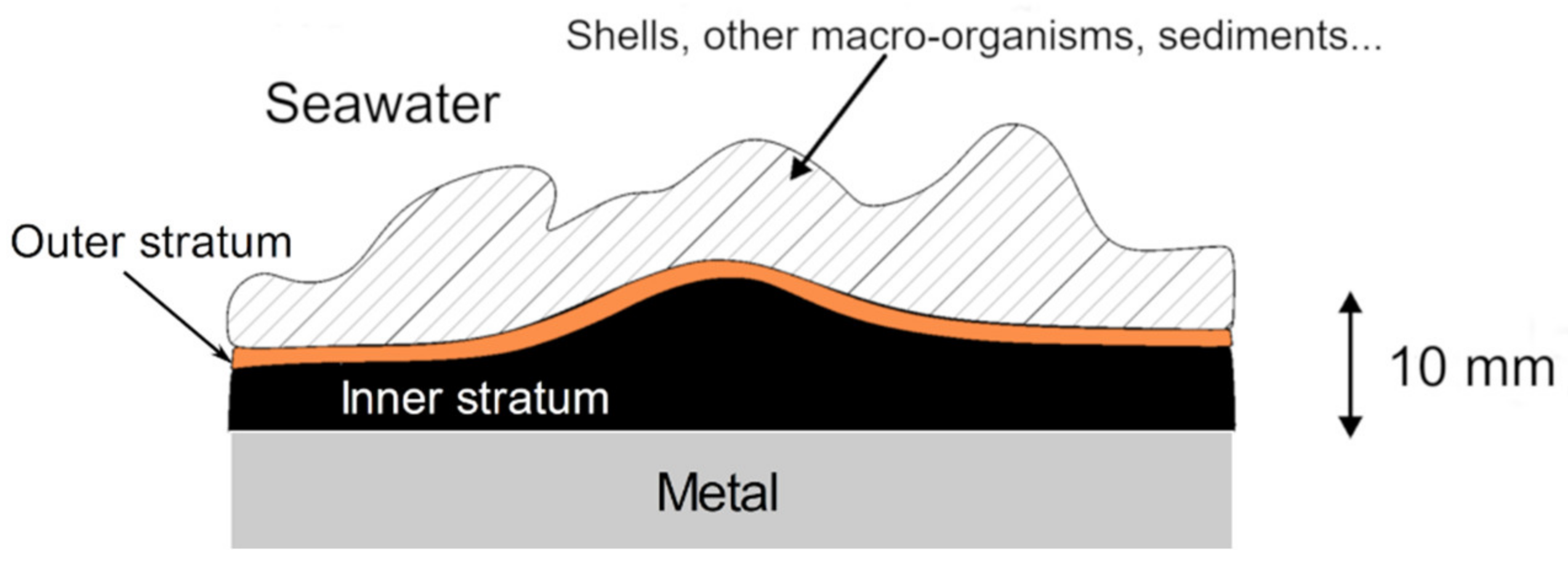
3.1. Stratification of the Corrosion Product Layer

After several years in natural seawater, the surface of carbon steel structures permanently immersed in natural seawater is covered by a corrosion product layer itself covered by biofouling. Figure 1 displays the main features of the layers formed on carbon steel coupons after 6 to 11 years of immersion [36,41,42,44].
The corrosion product layer can be several millimeters thick, reaching locally a thickness of 1 cm or more. Under the biofouling layer that may incorporate mineral compounds (sand, clay, fragments of shells) and macro-organisms, an orange-brown corrosion product layer is generally seen. This is the outer stratum, mainly composed of Fe(III)-oxyhydroxides (FeOOH). Lying underneath is found the inner stratum, characterized by a black color, that is in contact with the steel surface. This inner stratum is mainly composed of Fe(II)-based corrosion products, mixed with magnetite Fe3O4. The Fe(II)-based compounds are reactive towards oxygen and the Fe(III)-oxyhydroxides that constitute the orange-brown outer layer are the end products of their oxidation by dissolved O2. After 6–11 years in natural seawater, the inner black stratum is much thicker than the orange-brown outer stratum. This demonstrates that the steel surface and the main part of the corrosion product layer are no more reached by dissolved oxygen, i.e., that anoxic conditions are met. This explains why anaerobe microorganisms develop systematically inside the corrosion product layers and influence necessarily the corrosion process, as perfectly illustrated by the phenomenological model proposed by Melchers et al. [17,22]. Dissolved oxygen cannot reach the inner part of the corrosion product layer because the aerobe microorganisms that colonize the biofouling layer and the orange-brown outer stratum consume it. The little oxygen that could possibly reach the dark inner stratum would then react with the Fe(II)-based corrosion products to form FeOOH phases and/or magnetite.
The stratification of the corrosion product layer can be clearly observed as soon as 1–2 months of immersion [30].

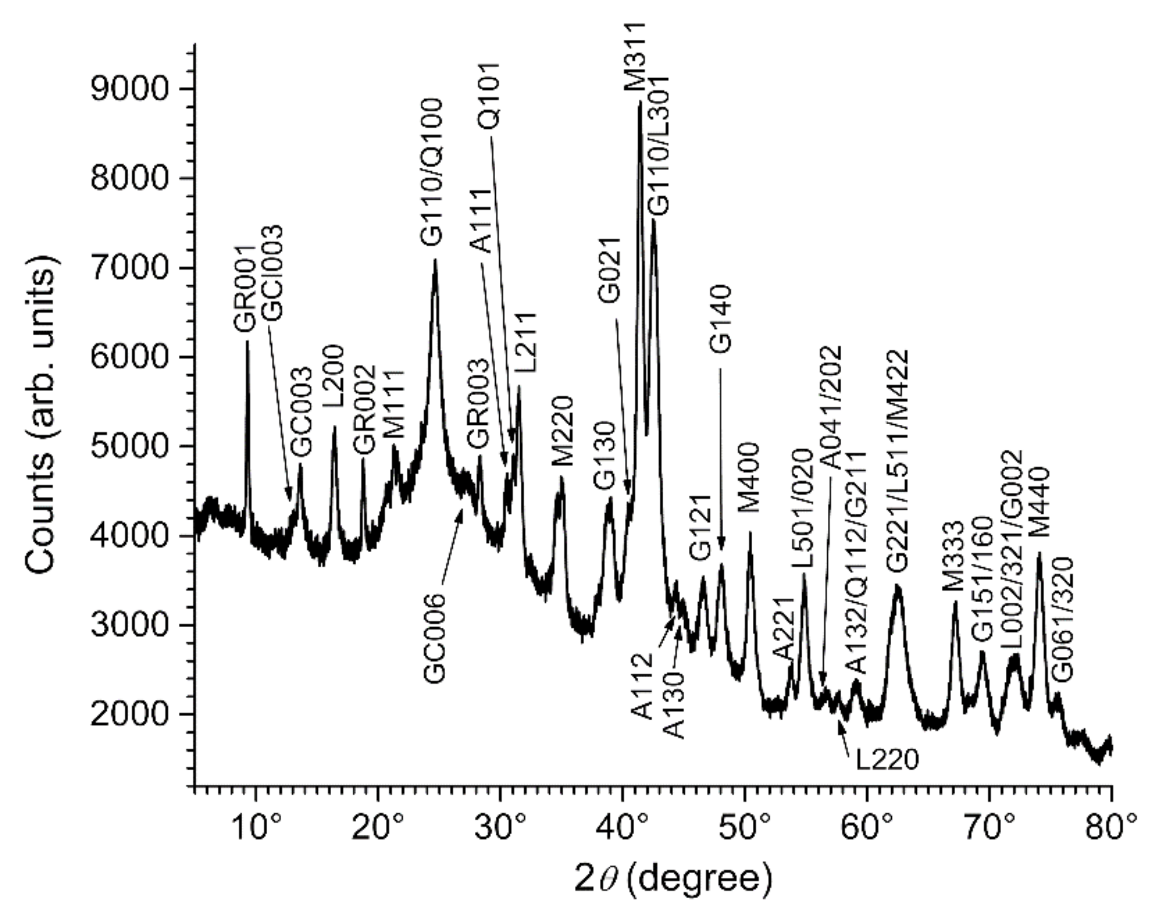
3.2. Composition of the Corrosion Product Layer

Figure 2 shows the XRD pattern of the corrosion product layer that covered a carbon steel coupon immersed 6 months in natural seawater (Les Minimes marina exposure site, La Rochelle, Atlantic Ocean). The main crystalline solid phases that constitute such corrosion product layers are all detected here. Two Fe(III)-oxyhydroxides, namely goethite α-FeOOH and lepidocrocite γ-FeOOH, are identified. They constitute the orange-brown outer stratum. Magnetite, the Fe(II,III) mixed-valence oxide Fe3O4, is identified too. It is present in the inner dark layer. Magnetite can form in anoxic conditions as shown by thermodynamic data e.g., [49,50]. The overall reaction involves the oxidation of three Fe(0) atoms to one Fe(II) cation and two Fe(III) cations, and the reduction of four water molecules to hydrogen. It can be written as:
3Fe + 4H2O → Fe3O4 + 4H2
This first process explains the formation of magnetite on or close to the metal surface. However, magnetite can also be obtained indirectly as an oxidation product of Fe(II)-based corrosion products at very low oxygen flow rates [51]. This second process explains why magnetite was in some cases mainly detected at the interface between the inner dark stratum and the outer orange stratum [41], where a small amount of oxygen can access after having crossed over the outer parts of the biofouling/corrosion product layer.
The other corrosion products identified via the XRD pattern of Figure 2 are green rust (GR) compounds, namely the sulfate GR, the carbonate GR, and the chloride GR. Green rust compounds are mixed-valence Fe(II,III) layered double hydroxides (LDH) mainly containing Fe(II) cations (67% to 75%). In contrast, magnetite contains mostly Fe(III) cations (67% i.e., only 33% of Fe(II) cations). The crystal structure of GR compounds consists of the stacking of hydroxide layers, built on Fe(OH)6 octahedra, carrying a positive charge because of the presence of the Fe(III) cations [52,53,54,55]. So-called interlayers constituted of anions and water molecules are intercalated between two adjacent hydroxide layers. Various GRs can be obtained depending on the anions present in the surrounding environment, and seawater, given its composition, can induce the formation of GR(Cl), GR(SO42−), and GR(CO32−).
The sulfate green rust is predominant as revealed by the numerous results accumulated in the past ten years [26,30,36,41,42]. This is also illustrated in Figure 2 by the higher relative intensity of the diffraction peaks of GR(SO42−). The chloride GR, which could be expected to be the predominant GR variety because of the high chloride concentration of seawater, was rarely identified or as a very minor compound. However, the stability of the various GR compounds does not only depend on the intercalated anion concentration. It depends on the geometry, size, and number of charges of the anion, or more generally, on any parameter that influences the stability of the LDH crystal structure. The studies dealing with the affinity of this structure for various anions revealed that divalent anions were generally preferred to monovalent ones [56,57,58]. In solutions characterized by large [Cl]/[SO42−] concentration ratios, it was demonstrated accordingly that GR(SO42−) was obtained preferentially to GR(Cl) [58].
Other compounds can be identified with the XRD pattern of Figure 2. Quartz, i.e., sand, comes from the environment. Aragonite, a CaCO3 phase, can also come from the environment as some shells are made of it. However, its formation may be associated with the corrosion process, as explained in Section 4.1.
Table 2 lists the compounds positively identified via XRD and/or µ-RS spectroscopy in the corrosion product layers formed on carbon steel permanently immersed in natural seawater, as reported in references [26,30,36,41,42,44]. Chukanovite Fe2(OH)2CO3 and greigite Fe3S4 were rarely identified and do not appear among the products revealed by the XRD pattern of Figure 2. In contrast, mackinawite FeS is one of the main corrosion products, present in the inner dark layer, but it is not detected either via the XRD pattern. This is generally the case because mackinawite is mainly found in a nanocrystalline state and is rarely identified by XRD [26,30,36,41,42,44]. It can however be detected using µ-Raman spectroscopy [59].
Figure 3 shows a picture obtained with the optical microscope of the µ-RS apparatus. It was taken during the analysis of the inner dark layer covering a carbon steel coupon immersed 6 years in natural seawater (exposure site: Naval Group laboratory, Cherbourg, English Channel). At the center of the image, a stack of thin bluish platelets can be seen. Only a part of these platelets is visible, as the rest is covered with shiny black matter, but one can see that these particles seem to have the characteristic hexagonal shape of GR crystals [36,41,60,61,62]. µ-RS analysis of these platelets (not shown) confirmed that they corresponded to a GR compound. The shiny black matter that surrounds them was also analyzed by µ-RS (Figure 4). Figure 4a displays the most commonly found spectrum. It is composed of two Raman peaks, the main one located at 283 cm−1 and the other one at 207 cm−1. This spectral signature is typical of nanocrystalline mackinawite [59]. This nanocrystalline compound, formerly considered as “amorphous FeS” or “poorly ordered FeS”, is the solid that precipitates from dissolved Fe(II) and S(-II) species [63,64]. Aging in the solution can improve the crystallinity but this process is very slow in alkaline conditions and at ambient temperatures [59]. In seawater (pH~8.1), mackinawite then remains essentially in its nanocrystalline state.
Figure 4b displays another Raman spectrum of the shiny black matter, less frequently observed than the previous one. First, the two Raman peaks of nanocrystalline mackinawite are seen, at 207 cm−1 and 282 cm−1. Secondly, other intense peaks are seen at 125 cm−1, 253 cm−1, 310 cm−1, and 364 cm−1. They are attributed to the so-called “Fe(III)-containing mackinawite”, a slightly oxidized form of mackinawite [59,65] that may contain up to 20% of Fe(III) [59,66]. The proposed chemical formula is then FeII1-3xFeIII2xS [59]. The in-situ oxidation of Fe(II) into Fe(III) can take place even in anoxic conditions, and this process finally leads to greigite Fe3S4 [65] via a solid-state transformation [67]. Actually, the spectrum of Figure 4b shows typical features of greigite that are the peaks at 143 cm−1, 194 cm−1, and 364 cm−1 (shared with Fe(III)-containing mackinawite) [65,68].
The iron sulfides are formed because of bacterial activity. Sulfide species are not present in seawater except in deaerated conditions that promote the growth and activity of sulfide-producing bacteria such as SRB. In studies combining a microbiological analysis of the bacterial flora with a characterization of the corrosion products, the presence of FeS was indeed associated with that of SRB (e.g., [18,26,27,30,69]). As explained above, anoxic conditions are established after some time in the inner black stratum of the corrosion product layers and consequently anaerobe microorganisms such as SRB can grow and be active. At the beginning of the corrosion process, only a few deaerated regions are found and FeS forms only locally. It could be detected in one particular zone of a steel coupon after 1 month of immersion, a finding associated with the concomitant detection of SRB [30]. After 6–12 months, FeS is scattered more or less homogeneously in the inner black layer [26], which indicates that anaerobic conditions prevail all over the steel surface. This corresponds to the moment when the influence of SRB becomes significant, as it affects the whole steel surface, a particular time of the corrosion process that is characterized by an increase of the corrosion rate [22,69].
Finally, maghémite (γ-Fe2O3) and ferrihydrite (Fe5HO8·4H2O) are two compounds possibly present as minor components of the orange outer stratum. They are difficult to characterize by XRD because: (i) the XRD pattern of maghémite is close to that of magnetite and (ii) ferrihydrite is a very poorly ordered and crystallized form of Fe(III)-(oxy)hydroxide. They could not be unambiguously identified in previous works [26,30,36,41,42,44] and for this reason, were omitted from Table 2.

3.3. GR(SO42−), the First Compound Resulting of the Corrosion of Carbon Steel in Seawater

Analysis of the corrosion product layers formed on carbon steel coupons after 1 week of immersion in natural seawater (Les Minimes marina, La Rochelle, Atlantic Ocean) revealed only two phases, the sulfate GR and lepidocrocite γ-FeOOH [30]. Actually, lepidocrocite is the main oxidation product of GR(SO42−) by dissolved O2 [58], which indicates that GR(SO42−) is the first solid phase to form from the dissolved species produced by the corrosion of the metal. This point was confirmed by anodic polarization experiments performed with carbon steel electrodes immersed in artificial seawater-like solutions deaerated with argon [36]. After 15 min, 3 h, and 26 h of polarization, only the sulfate GR (with traces of the carbonate GR) could be identified on the steel surface.
The formation of GR compounds in seawater-like conditions was also studied using another method. GR compounds could be precipitated by mixing a solution of NaCl, Na2SO4·10H2O, FeCl2·4H2O, and FeCl3·6H2O with a solution of NaOH [70]. The obtained precipitates were analyzed immediately after their formation and after 1 week of aging in suspension at room temperature. The initial precipitate was in any case a mixture of GR(SO42−) with GR(Cl). After one week of aging, only traces of GR(Cl) remained, GR(SO42−) being the final result of the overall process. This study shows that GR(Cl) may be an intermediate transient compound, rapidly transformed to GR(SO42−). This would explain why GR(Cl) could be sometimes identified, always in small amounts, in the dark inner stratum of the corrosion product layer.
From all these findings, it can be proposed that GR(SO42−) forms from the dissolved Fe(II) species produced by the corrosion of steel through the process illustrated in Figure 5. This process may take place within a few minutes or a few seconds as GR(SO42-) was the only product detected after 15 min of immersion [36].
It is generally admitted that the Fe2+ cations produced by the anodic reaction precipitate first with the OH ions produced by the cathodic reaction (see Section 4.1), which leads to the Fe(II) hydroxide Fe(OH)2. The crystal structure of Fe(OH)2 is based on sheets formed by hydroxide-bridged FeII(OH)6 octahedra. The formation of the solid phase may then begin by the formation of small units of such sheets, where Cl and SO42− anions (predominant in seawater) are adsorbed (Figure 5a). At the pH of seawater, Fe(OH)2 can be oxidized to GR(SO42−) even in anoxic conditions [50], so that in any case some Fe(II) cations are rapidly oxidized to Fe(III). A FeIII(OH)6 octahedron necessarily bears an excess positive charge and attracts anions, facilitating their adsorption on the forming hydroxide sheets, as illustrated in Figure 5b with the example of a sulfate anion. The stacking of such Fe(III)-containing hydroxide sheets, with intercalated anions and water molecules, actually corresponds to the structure of GR compounds [52,53,54,55], as explained in previous Section 3.1. Since divalent anions give greater stability to this structure, Cl ions should be finally expelled from the interlayers, finally leading to GR(SO42−) as illustrated in Figure 5c.
The overall process leading from the Fe(II) dissolved species to the first solid corrosion product, i.e., GR(SO42−), can then be summarized by the reactions (2), if dissolved O2 is present, or (3), if anoxic conditions are established:
6Fe2+ + 10OH + SO42− + ½O2 + 9H2O → FeII4FeIII2(OH)12SO4⋅8H2O
6Fe2+ + 10OH + SO42− + 10H2O → FeII4FeIII2(OH)12SO4⋅8H2O + H2

4. Characterization of Anodic and Cathodic Zones

4.1. Heterogeneity of the Corrosion Product Layer and Role of Interfacial pH

The use of sufficiently large carbon steel coupons, e.g., 10 cm × 10 cm sized coupons, generally enables us to observe the heterogeneity of the corrosion process [41]. An example is displayed in Figure 6, showing the surface of a coupon after 6 years in seawater. Although the coupon surface is mostly covered by biofouling and macro-organisms (a shell is visible near the center) different zones can be easily distinguished. At the bottom (middle of the lower edge) of the coupon, a large orange tubercle has formed. This accumulation of corrosion products indicates that the corrosion process has been accelerated here. The underlying metal surface then more likely corresponds to an anodic zone. This can be rigorously demonstrated after the corrosion product layer is removed via the determination of the localized degradation depth [9,41,42]. Other zones are covered by a much thinner dark layer of corrosion products, as indicated in Figure 6, where the corrosion rate was less important. They correspond to cathodic zones of the underlying carbon steel surface.
The formation of cathodic zones, where the cathodic reaction rate is higher than that of the anodic reaction rate, and anodic zones, where the cathodic reaction rate is lower than the anodic reaction rate, may have various origins. The possible causes of localized corrosion are well established and include the inherent heterogeneity of the biofilm, the differential aeration cells (especially for vertical surfaces), and the heterogeneity of the steel surface (inclusions, welds, segregation…). The possible persistence of the galvanic coupling between anodic and cathodic zone is however governed, for long immersion times, by the properties of the corrosion product layers that progressively grow on each zone. The detailed characterization of the products forming in cathodic and anodic zones was then a key point towards the understanding of the long-term localized corrosion processes of carbon steel in seawater [41,42].
The thick tubercles of corrosion products such as the one shown in Figure 6 are, like the corrosion product layers resulting from uniform corrosion, composed of two main strata, an inner dark stratum in contact with the metal surface and an outer orange-brown stratum [41,42]. Figure 7 displays the XRD pattern of a fragment of the inner dark stratum sampled close to the metal surface in an anodic zone. This pattern is mainly composed of the diffraction peaks of the sulfate GR that are very intense. Other GR compounds are not identified and only the main diffraction peak of magnetite (M311) is clearly seen.
Figure 8 displays the XRD pattern of a fragment of the whole dark layer that covered a cathodic zone of the metal surface. The most intense peak is in this case the main diffraction peak M311 of magnetite. The diffraction peaks of other GR compounds are now clearly detected, and those of the carbonate GR are particularly intense. Aragonite is also clearly identified. The Fe(III)-oxyhydroxides are minor components of the corrosion product layer formed in this cathodic area, in agreement with its visual aspect (black color). This demonstrates that the composition of the corrosion product layer depends on the anodic/cathodic character of the underlying metal surface.
Iron sulfides were identified in any case in both anodic and cathodic zones using µ-RS. Actually, the Raman spectra of mackinawite displayed in Figure 4 were obtained from the corrosion product layer covering a cathodic zone. This demonstrates that SRB can grow and be active in both kinds of zones, which mainly indicates that oxygen does not reach the inner dark layer neither in the anodic nor in the cathodic zones (this point is further discussed in Section 4.4). At the present time, it is not possible to state whether SRB develops first or preferentially in one kind of zone.
In Table 2 that lists the products positively identified inside the corrosion product layers [26,30,36,41,42,44], it is indicated whether a compound is preferentially formed in anodic or cathodic zones. The compounds favored in cathodic zones are carbonate-containing phases, namely aragonite, chukanovite, and GR(CO32−), and magnetite. In each case, the main reason is the increase of the interfacial pH induced by the difference between the cathodic and the anodic reaction rates. On a metal surface where uniform corrosion takes place, the cathodic and anodic reaction rates are equal. The anodic reaction produces Fe2+ cations:
Fe → Fe2+ + 2e
The corresponding cathodic reaction, whether it is O2 or H2O reduction, produces 2 OH ions per 2 consumed electrons:
½O2 + H2O + 2e → 2OH
2H2O + 2e → H2 + 2OH
Fe2+ and OH ions are then produced in a ratio OH/Fe2+ = 2 and subsequently incorporated inside the solid phases that constitute the corrosion product layer. This is commonly summarized by the following reaction:
Fe2+ + 2OH → Fe(OH)2
As discussed in Section 3.3, the formation of Fe(II)-hydroxide sheets is rapidly followed in seawater by that of GR(SO42−) but, as shown by reaction (7), the pH at the steel/seawater interface is unaffected. The same conclusion is drawn if another corrosion product is considered, as illustrated by the example of magnetite formation (reaction 1). In cathodic zones, the rates of reduction reactions (5) and/or (6) is higher than that of the anodic reaction (4) because part of the consumed electrons comes from the anodic zones. The ratio between the produced OH and Fe2+ ions in a cathodic zone is then higher than 2, which induces an increase of the interfacial pH. This effect is well-known for steel structures subjected to cathodic protection and leads to the formation of the so-called calcareous deposit, mainly composed of aragonite CaCO3 e.g., [44,71,72,73,74]. The presence of aragonite among the corrosion products of steel inside the layers forming on a cathodic zone is then clearly associated with the increase of the interfacial pH. This assumption was confirmed via experiments performed in artificial seawater where shells, the other possible origin of aragonite, were of course not present [9]. The increase of the interfacial pH leads to changes in the inorganic carbonic equilibrium at the metallic interface and favor CO32− over HCO3:
HCO3 + OH → CO32− + H2O
This explains why the formation of aragonite is not the only process favored in the cathodic zones: the formation of other CO32− based compounds, i.e., chukanovite and GR(CO32−), is also facilitated.
In contrast, the ratio between the produced OH and Fe2+ ions is lower than 2 in the anodic zones. As Fe2+ is a Lewis acid, the interfacial pH may tend to decrease in the anodic areas. This well-known phenomenon is the origin of various localized corrosion phenomena such as crevice corrosion, pitting corrosion, etc...

4.2. Equilibrium Conditions between GR(SO42−) and GR(CO32−)

The formation of GR(CO32−) in the cathodic zones was thoroughly studied. The first results were obtained with a study of the impact of cathodic protection on aged (5 years of immersion) and already strongly corroded carbon steel coupons. It was observed after one year of cathodic polarization that the whole amount of GR(SO42−) initially present in the corrosion product layers had been entirely transformed to GR(CO32−) [44]. The reaction induced by the polarization can be written as follows:
FeII4FeIII2(OH)12SO4⋅8H2O + CO32− → FeII4FeIII2(OH)12CO3⋅2H2O + 6H2O + SO42−
This writing clearly shows that the transformation is favored by the increase of the CO32− concentration. More precisely, the equilibrium conditions between GR(SO42−) and GR(CO32−) are governed by the pH, the sulfate concentration, and the carbonate species concentration [9,44]. This can be highlighted by writing the reaction with the main carbonate dissolved species present in seawater, i.e., HCO3:
FeII4FeIII2(OH)12SO4⋅8H2O + HCO3 ⇆ FeII4FeIII2(OH)12CO3⋅2H2O + 6H2O + SO42− + H+
The equilibrium conditions are then expressed by:
pK = pH – log[a(SO42−)/a(HCO3)]
In Equation (11), a(SO42−) and a(HCO3) are the activities of SO42− and HCO3 in the solution where GR(SO42−) and GR(CO32−) coexist. A study of these equilibrium conditions was achieved to obtain a numerical value of the equilibrium constant [9], which led to:
pK = 7.85 ± 0.35
Using the typical values of a(SO42−) and a(HCO3) for seawater [9], it was computed that the pH corresponding to the equilibrium conditions between both GR compounds was equal to 8.24 ± 0.35 [9], which is similar or only slightly higher than the average pH of seawater. This explains why a slight increase of the interfacial pH can indeed favor the formation of GR(CO32−) at the detriment of that of GR(SO42−).

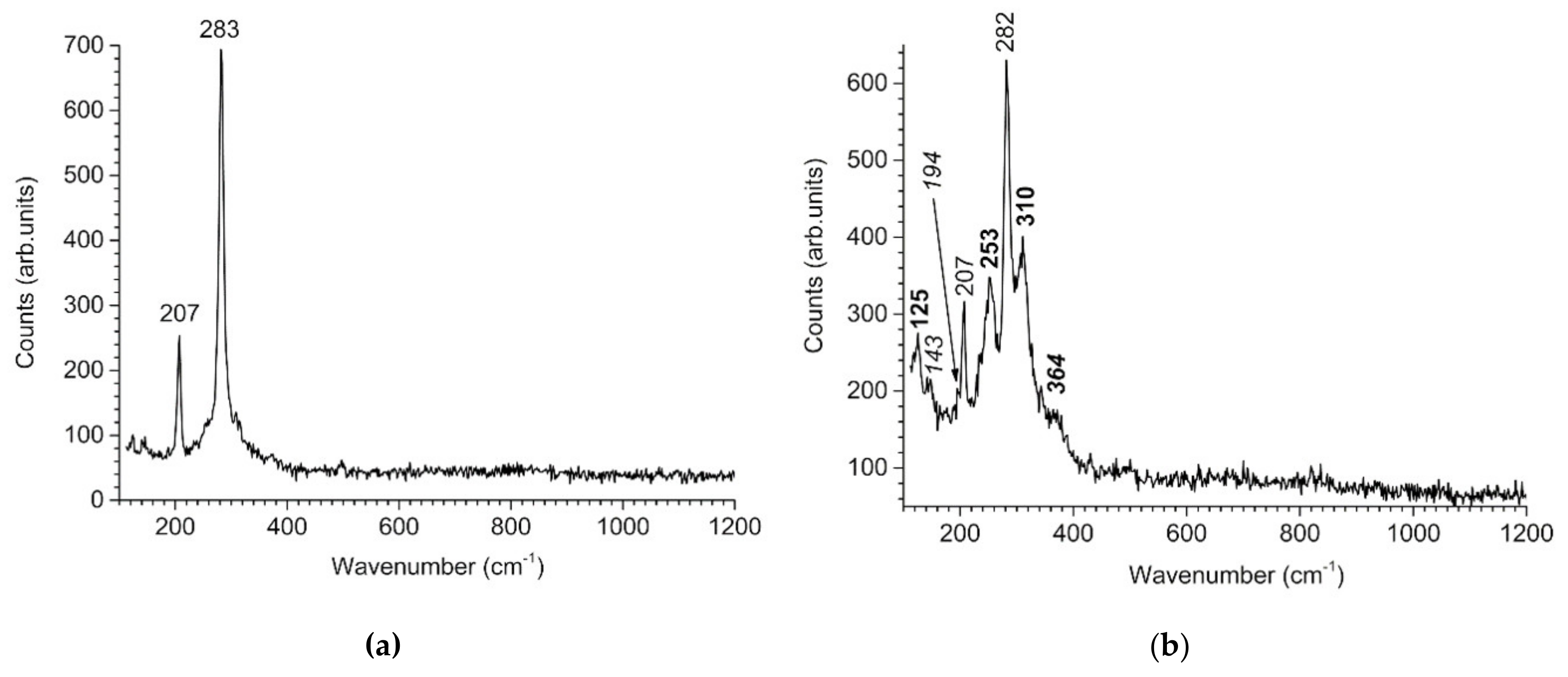
4.3. Variations of the Magnetite Content

The key point is however the competitive formation processes of magnetite and GR(SO42−) because magnetite is a well-known electronic conductor [32,33,34] whereas, to our better knowledge, GR(SO42−) is an insulator. According to thermodynamic data, magnetite would indeed be favored by an increase of pH, and conversely, GR(SO42−) by a decrease of pH [50]. This was also confirmed by experimental results [50].
As for the corrosion product layers formed on carbon steel permanently immersed in seawater, the relative proportions of magnetite and GR(SO42−) proved to depend on the anodic/cathodic character of the underlying metal surface. This is illustrated by the results synthesized in Table 3.
This table gathers data from [41,42] and unpublished results coming from the same research program. To quantify the changes in the relative proportions of magnetite and GR(SO42−) revealed by XRD analysis, the M311 diffraction line intensity to GR003 diffraction line intensity ratio, i.e., I(M311)/I(GR003), was used. This ratio was chosen because, in the considered experimental conditions (Naval Group laboratory, Cherbourg, English Channel), it was close to 1 (actually between 0.77 and 1.05) for the corrosion product layers generated by uniform corrosion [41]. After 6 years of immersion in these conditions, the average corrosion rate was determined, from thickness loss measurements, to be equal to 0.07 ± 0.02 mm/year for uniform corrosion. Therefore, a zone of the metal surface where the local corrosion rate is significantly higher than 0.07 mm/year should be considered as an anodic zone. Conversely, if the local corrosion rate is significantly lower than 0.07 mm/year then this part of the steel surface should be considered as a cathodic zone.
The data related to the various analyzed zones are listed in Table 3 with decreasing measured local corrosion rates or, in other words, from the most severely degraded areas (0.5 mm/year, top line) to less degraded regions (0.01 mm/year, bottom line). In each case, the corrosion product layer covering the metal was analyzed by XRD so that the composition of the layer could be associated with the corrosion rate. It can then be seen in Table 3 that the I(M311)/I(GR003) ratio determined from the XRD analysis increases with decreasing corrosion rate. This trend is more clearly illustrated by the diagram displayed in Figure 9, where the average value of the I(M311)/I(GR003) ratio is plotted against the average local corrosion rate. This clearly shows that the magnetite content of the corrosion product layer increases with the cathodic character of the metal surface.

4.4. The Localized Corrosion Mechanism Associated with Magnetite-Rich Cathodic Zones

As described in the previous section, the corrosion product layers covering cathodic zones are significantly enriched with magnetite that is an electronic conductor. Moreover, these layers do not contain, or only in small amounts, FeOOH compounds [41,42], in agreement with visual observations: these layers are black, i.e., the orange-brown outer stratum composed of FeOOH compounds did not form. This is only possible if dissolved O2 does not react with the Fe(II)-based compounds present in the corrosion product layer. This means that the O2 molecules reaching the outer surface of the corrosion product layer are consuming, through the reduction process, electrons coming from another part of the system, i.e., necessarily the anodic zones of the steel surface. This process is possible only if an electronic pathway exists inside the corrosion product layer. This pathway can be constituted by a network of interconnected magnetite particles also connected to the metal surface. Such a network may indeed be present in the magnetite-rich layers covering the cathodic zones, that are moreover much thinner than those covering the anodic zones ([41,42], see also Figure 6). A schematic representation of the mechanism is presented in Figure 10.
Actually, the anodic zones of the metal surface are thick and enriched with insulating compounds such as Fe(III)-oxyhydroxides and GR(SO42−). Dissolved O2 cannot reach the metal surface underneath or be reduced at the surface of magnetite particles that are present in small amounts and consequently not interconnected. It is consumed in the outer stratum by aerobe microorganisms or in the dark inner stratum through its reaction with Fe(II)-based corrosion products.
Localized corrosion can only lead to severe issues if it can persist for a long time. The particular mechanism associated with the heterogeneity of the corrosion product layers is based on the assumption that dissolved O2 participates in the corrosion process because it can be reduced on the outer surface of the magnetite-rich layer covering the cathodic zones [41]. Since the formation of magnetite is favored by an increase of pH, this mechanism has then a self-sustaining ability as it creates conditions that favor its own persistence: If oxygen reduction takes place preferentially in the cathodic zones, then the interfacial pH increases and consequently the formation of magnetite is favored. Conversely, the process favors a decrease of pH in the anodic zones that hinders the formation of magnetite and leads to an accumulation of insulating compounds on the metal surface.
The role of SRB in this mechanism may also be important. Anaerobic conditions are met at the metal surface in both anodic and cathodic zones and SRB can grow and be active in both zones, as demonstrated by the identification of FeS in any case. In the cathodic zones, dissolved O2 may reach the outer part of the dark corrosion product layer covering the metal before to be reduced at the surface of magnetite particles so that SRB would preferentially develop closer to the metal. In any case, iron sulfides are electronic conductors [16,23] and their formation in the cathodic zones would then favor the persistence of the corrosion cell described above thus reinforcing the corresponding localized corrosion mechanism. Electroactive SRB [23,24,25] could also take advantage of the interconnected Fe3O4/FeS particles network linked to the metal surface in the cathodic zones, and favor its persistence.
Finally, this process would stop once:
(i)
the layer covering the cathodic zone is covered by a thick layer of biofouling/calcareous deposit that prevents (as in anodic zones) dissolved O2 to reach magnetite particles,
(ii)
the corrosion product layer covering the cathodic zone becomes so thick that the network of interconnected Fe3O4/FeS particles is no more linked to the metal surface.

5. Oxidation of the Corrosion Product Layers and FORMATION of Akaganeite

Akaganeite (β-FeOOH) is a common corrosion product of steel in marine atmospheres e.g., [38,39,75,76]. Though it is considered as the β-phase of Fe(III) oxyhydroxides, it necessarily contains Cl ions and its chemical formula is more exactly FeO1−x(OH)1+xClx [77]. However, akaganeite was rarely observed, and always as a minor component, in the studies [26,30,36,41,42,44] dealing with corrosion products formed on carbon steel permanently immersed in seawater.
The corrosion processes involved during permanent immersion are of course different from those of atmospheric corrosion. The wet/dry cycles typical of atmospheric corrosion induce oxidation and transformation of Fe(II) species/compounds that do not take place during permanent immersion and may be responsible for the formation of akaganeite. To clarify this point a coupon was, after 1 year of immersion in natural seawater, exposed 11 days to the atmosphere of the laboratory so that the corrosion product layer dried completely. This layer was then analyzed by XRD and the result is shown in Figure 11.
The Fe(III)-based compounds already formed during the immersion period, i.e., magnetite, lepidocrocite, and goethite, are the main components of the dried oxidized layer. The Fe(II)-based corrosion products, i.e., GR compounds, are not detected anymore. They were integrally oxidized and transformed into Fe(III) compounds during the 11 days of exposure to air. Aragonite is also identified, it comes more likely from a cathodic zone of the metal. Calcite is also present but may come from fragments of shells. The drying of the sample has moreover induced the formation of NaCl (halite). Finally, another Fe(III) compound, not initially present in the corrosion product layer, is now identified: it is akaganeite.
This shows that akaganeite may mostly result from the oxidation and drying of corrosion product layers previously formed during the immersion of steel in seawater. Actually, the formation of akaganeite requires a high concentration of both dissolved Fe(II) and Cl species [78]. During the drying of a corrosion product layer, water evaporates progressively and dissolved species (Cl, Fe2+) concentrations increase continuously until the formation of akaganeite is possible. The overall reaction could be written as:
4Fe2+ + O2 + 6H2O + 4HCl → 4FeO1−x(OH)1+xClx + 8H+
Note that intermediate compounds/species could be involved, e.g., GR(Cl) [78,79], Fe(II)-hydroxychloride [78,79] or dissolved Fe(III) species.
This result points out the necessity to shelter the corrosion product layer from the air before and during analysis. First, the Fe(II)-based compounds must be preserved because, as they form directly from the dissolution of steel, they convey the most important information about the corrosion mechanism. Secondly, the formation of compounds not really associated with the corrosion process must be avoided because it may lead to a misinterpretation of the mechanisms involved.
A final corrosion product must be discussed, the Fe(II)-hydroxychloride β-Fe2(OH)3Cl known as a precursor of akaganeite [78,79]. Though it has not been clearly identified on “modern” steel structures, it has however been reported as the main component of the corrosion product layer covering Gallo-Roman iron ingots that remained at the bottom of the Mediterranean Sea for 2000 years [43]. This finding shows that the corrosion mechanisms may change drastically after a (very) long time of permanent immersion in seawater. However, no information is currently available about this possible transition period and the associated mechanisms and processes.

6. Conclusions

The thorough characterization of the corrosion product layers provided important information that led to a better understanding of the mechanisms of marine corrosion of carbon steel permanently immersed in natural seawater. Important facts must be pointed out:
-
It is generally admitted that, after a sufficiently long immersion time (variable but at least 6 months), anoxic conditions are met at the steel surface and inside the inner part of the corrosion product layer. Anaerobe microorganisms such as SRB can develop and be active, which leads to the formation of iron sulfides. Marine corrosion is then intrinsically a biologically influenced process and its complexity cannot be entirely mimicked by laboratory experiments and/or using artificial seawater. The biofilm itself and other microorganisms are also known to have an influence on corrosion processes.
-
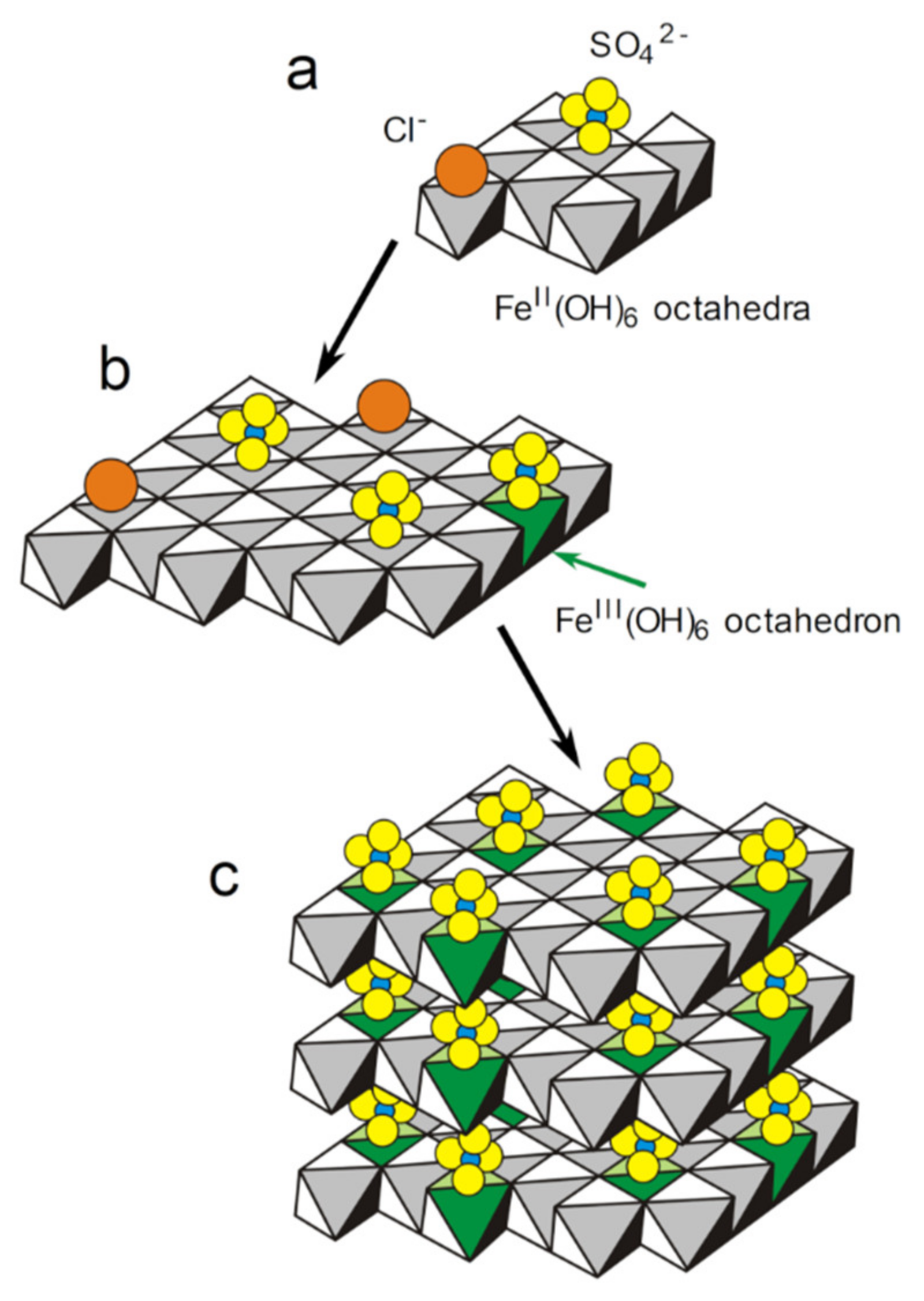
The first solid phase to form on the steel surface is the sulfate GR. It is favored, with respect to magnetite and carbonate GR, in the anodic zones, by the decrease of the interfacial pH. A mechanism is proposed, involving (i) the adsorption of anions (mainly Cl and SO42−) on the nuclei of Fe(OH)2 hydroxide sheets, (ii) the oxidation of part of the Fe(II) cations to Fe(III) in the hydroxide sheets and (iii) the stacking of the sheets leading to GR(SO42−) after the release of Cl ions.
-
A particular mechanism can however involve oxygen even if anoxic conditions are established at the steel surface. The pH proved to have a significant influence on the composition of the corrosion product layer and this composition then depends on the anodic/cathodic character of the underlying metal surface. In cathodic zones, the increased interfacial pH favors the formation of magnetite (among other compounds) that is an electronic conductor. Associated with a low corrosion rate, the process then leads to a magnetite-rich layer that remains moderately thick (~2–5 mm) even after 6–8 years [41,42]. The reduction of dissolved O2 can then take place at the outer surface of this layer as long as the magnetite particles remain interconnected and connected to the steel surface.
-
The activity of SRB (and other sulfide-producing bacteria) in the cathodic zones may favor and reinforce this mechanism because it generates additional conductive corrosion products, i.e., iron sulfides.
-
Finally, it is necessary to preserve the samples from air to avoid the transformation of Fe(II)-based compounds. The nature of these compounds is directly related to the corrosion mechanisms. Moreover, the oxidation/transformation of the Fe(II)-based corrosion products may produce other compounds (e.g., akaganeite), thus possibly leading to an erroneous interpretation of the mechanisms.

Author Contributions

Conceptualization, all authors; methodology, all authors; validation, all authors; formal analysis, all authors; investigation, all authors; writing—original draft preparation, P.R.; writing—review and editing, all authors; visualization, P.R., M.J.; supervision, A.-M.G., P.R.; project administration, A.-M.G., P.R.; funding acquisition, A.-M.G., P.R. All authors have read and agreed to the published version of the manuscript.

Funding

The various studies synthesized here were funded by: the Technological Research Institute Jules Verne of Nantes (France) through the ADUSCOR research program; the European Regional Development Fund (ERDF) and the CDA of La Rochelle through the DYPOMAR research project; the seaports (GPM) of La Rochelle, Nantes-Saint-Nazaire, Marseille, and Le Havre.

Conflicts of Interest

The authors declare no conflict of interest.

References

  1. Chaves, I.A.; Melchers, R.E. Long term localised corrosion of marine steel piling welds. Corros. Eng. Sci. Technol. 2013, 48, 469–474. [Google Scholar] [CrossRef]
  2. Melchers, R.E.; Jeffrey, R.J.; Usher, K.M. Localized corrosion of steel sheet piling. Corros. Sci. 2014, 79, 139–147. [Google Scholar] [CrossRef]
  3. Melchers, R.E.; Chaves, I.A.; Jeffrey, R. A conceptual model for the interaction between carbon content and manganese sulphide inclusions in the short-term seawater corrosion of low carbon steel. Metals 2016, 6, 132. [Google Scholar] [CrossRef] [Green Version]
  4. Liu, C.; Cheng, X.; Dai, Z.; Liu, R.; Li, Z.; Cui, L.; Chen, M.; Ke, L. Synergistic effect of Al2O3 inclusion and pearlite on the localized corrosion evolution process of carbon steel in marine environment. Materials 2018, 11, 2277. [Google Scholar] [CrossRef] [PubMed] [Green Version]
  5. Liduino, V.S.; Lutterbach, M.T.S.; Sérvulo, E.F.C. Biofilm activity on corrosion of API 5L X65 steel weld bead. Colloids Surf. B Biointerfaces 2018, 172, 43–50. [Google Scholar] [CrossRef]
  6. Evans, U.R. The Corrosion and Oxidation of Metals: Scientific Principles and Practical Applications; Edward Arnold (Publishers) Ltd.: London, UK, 1960. [Google Scholar]
  7. Jeffrey, R.; Melchers, R.E. Corrosion of vertical mild steel strips in seawater. Corros. Sci. 2009, 51, 2291–2297. [Google Scholar] [CrossRef]
  8. Zou, Y.; Wang, J.; Bai, Q.; Zhang, L.L.; Peng, X.; Kong, X.F. Potential distribution characteristics of mild steel in seawater. Corros. Sci. 2012, 57, 202–208. [Google Scholar] [CrossRef]
  9. Duboscq, J.; Sabot, R.; Jeannin, M.; Refait, P.H. Localized corrosion of carbon steel in seawater: Processes occurring in cathodic zones. Mater. Corros. 2019, 70, 973–984. [Google Scholar] [CrossRef]
  10. Lee, W.; Lewandowski, Z.; Nielsen, P.H.; Hamilton, W.A. Role of sulfate-reducing bacteria in corrosion of mild steel: A review. Biofouling 1995, 8, 165–194. [Google Scholar] [CrossRef]
  11. Starovetsky, D.; Khaselev, O.; Starovetsky, J.; Armon, R.; Yahalom, J. Effect of iron exposure in SRB media on pitting initiation. Corros. Sci. 2000, 42, 345–359. [Google Scholar]
  12. Huang, Y.; Duan, J.; Ma, S. Effects of anaerobe in sea bottom sediment on the corrosion of carbon steel. Mater. Corros. 2004, 55, 46–48. [Google Scholar] [CrossRef]
  13. Jeffrey, R.; Melchers, R.E. The changing topography of corroding mild steel surfaces in seawater. Corros. Sci. 2007, 49, 2270–2288. [Google Scholar] [CrossRef]
  14. Castaneda, H.; Benetton, X.D. SRB-biofilm influence in active corrosion sites formed at the steel-electrolyte interface when exposed to artificial seawater conditions. Corros. Sci. 2008, 50, 1169–1183. [Google Scholar] [CrossRef]
  15. Beech, I.B.; Campbell, S.A. Accelerated low water corrosion of carbon steel in the presence of a biofilm harbouring sulphate-reducing and sulphur-oxidising bacteria recovered from a marine sediment. Electrochim. Acta 2008, 54, 14–21. [Google Scholar] [CrossRef]
  16. Dong, Z.H.; Shi, W.; Ruan, H.M.; An Zhang, G. Heterogeneous corrosion of mild steel under SRB-biofilm characterised by electrochemical mapping technique. Corros. Sci. 2011, 53, 2978–2987. [Google Scholar] [CrossRef]
  17. Melchers, R.E.; Jeffrey, R. Corrosion of long vertical steel strips in the marine tidal zone and implications for ALWC. Corros. Sci. 2012, 65, 26–36. [Google Scholar] [CrossRef]
  18. Stipaničev, M.; Turcu, F.; Esnault, L.; Schweitzer, E.W.; Kilian, R.; Basseguy, R. Corrosion behavior of carbon steel in presence of sulfate-reducing bacteria in seawater environment. Electrochim. Acta 2013, 113, 390–406. [Google Scholar] [CrossRef] [Green Version]
  19. World Steel Association. “World Steel in Figures 2019”, Brussels, Belgium. 2019. Available online: https://www.worldsteel.org/publications/infographics.html (accessed on 2 June 2020).
  20. Melchers, R.E. Mathematical modelling of the diffusion controlled phase in marine immersion corrosion of mild steel. Corros. Sci. 2003, 45, 923–940. [Google Scholar] [CrossRef]
  21. Melchers, R.E.; Jeffrey, R. Early corrosion of mild steel in seawater. Corros. Sci. 2005, 47, 1678–1693. [Google Scholar] [CrossRef]
  22. Melchers, R.E.; Wells, T. Models for the anaerobic phases of marine immersion corrosion. Corros. Sci. 2006, 48, 1791–1811. [Google Scholar] [CrossRef]
  23. Enning, D.; Venzlaff, H.; Garrelfs, J.; Dinh, H.T.; Meyer, V.; Mayrhofer, K.J.J.; Hassel, A.W.; Stratmann, M.; Widdel, F. Marine sulfate-reducing bacteria cause serious corrosion of iron under electroconductive biogenic mineral crust. Environ. Microbiol. 2012, 14, 1772–1787. [Google Scholar] [CrossRef] [PubMed] [Green Version]
  24. Venzlaff, H.; Enning, D.; Srinivasan, J.; Mayrhofer, K.J.J.; Hassel, A.W.; Widdel, F.; Stratmann, M. Accelerated cathodic reaction in microbial corrosion of iron due to direct electron uptake by sulfate-reducing bacteria. Corros. Sci. 2013, 66, 88–96. [Google Scholar] [CrossRef] [Green Version]
  25. Yu, L.; Duan, J.; Du, X.; Huang, Y.; Hou, B. Accelerated anaerobic corrosion of electroactive sulfate-reducing bacteria by electrochemical impedance spectroscopy and chronoamperometry. Electrochem. Commun. 2013, 26, 101–104. [Google Scholar] [CrossRef]
  26. Pineau, S.; Sabot, R.; Quillet, L.; Jeannin, M.; Caplat, C.H.; Dupont-Morral, I.; Refait, P.H. Formation of the Fe(II-III) hydroxysulphate green rust during marine corrosion of steel associated to molecular detection of dissimilatory sulphite-reductase. Corros. Sci. 2008, 50, 1099–1111. [Google Scholar] [CrossRef]
  27. Duan, J.; Wu, S.; Zhang, X.; Huang, G.; Du, M.; Hou, B. Corrosion of carbon steel influenced by anaerobic biofilm in natural seawater. Electrochim. Acta 2008, 54, 22–28. [Google Scholar] [CrossRef]
  28. Boudaud, N.; Coton, M.; Coton, E.; Pineau, S.; Travert, J.; Amiel, C. Biodiversity analysis by polyphasic study of marine bacteria associated with biocorrosion phenomena. J. Appl. Microbiol. 2010, 109, 166–179. [Google Scholar] [CrossRef]
  29. Usher, K.M.; Kaksonen, A.H.; MacLeod, I.D. Marine rust tubercles harbour iron corroding archaea and sulphate reducing bacteria. Corros. Sci. 2014, 83, 189–197. [Google Scholar] [CrossRef]
  30. Lanneluc, I.; Langumier, M.; Sabot, R.; Jeannin, M.; Refait, P.; Sablé, S. On the bacterial communities associated with the corrosion product layer during the early stages of marine corrosion of carbon steel. Int. Biodeter. Biodegrad. 2015, 99, 55–65. [Google Scholar] [CrossRef]
  31. Stipanicev, M.; Turcu, F.; Esnault, L.; Rosas, O.; Basseguy, R.; Sztyler, M.; Beech, I.B. Corrosion of carbon steel by bacteria from North Sea offshore seawater injection systems: Laboratory investigation. Bioelectrochemistry 2014, 97, 76–88. [Google Scholar] [CrossRef] [Green Version]
  32. Rlinger, M.I.; Samokhvalov, A.A. Electron conduction in magnetite and ferrites. Phys. Stat. Sol. B 1977, 79, 9–48. [Google Scholar] [CrossRef]
  33. Ihle, D.; Lorenz, B. Small-polaron band versus hopping conduction in Fe3O4. J. Phys. C Solid State Phys. 1985, 18, L647–L650. [Google Scholar] [CrossRef]
  34. Lopez Maldonado, K.L.; de la Presa, P.; de la Rubia, M.A.; Crespo, P.; de Frutos, J.; Hernando, A.; Matutes-Aquino, J.A.; Elizalde Galindo, J. Effects of grain boundary width and crystallite size on conductivity and magnetic properties of magnetite nanoparticles. J. Nanopart. Res. 2014, 16, 2482. [Google Scholar] [CrossRef]
  35. Li, Y.; Hou, B.; Li, H.; Zhang, J. Corrosion behavior of steel in Chengdao offshore oil exploitation area. Mater. Corros. 2004, 55, 305–309. [Google Scholar] [CrossRef]
  36. Refait, P.; Nguyen, D.D.; Jeannin, M.; Sablé, S.; Langumier, M.; Sabot, R. Electrochemical formation of green rusts in deaerated seawater-like solutions. Electrochim. Acta 2011, 56, 6481–6488. [Google Scholar] [CrossRef]
  37. Refait, P.; Jeannin, M.; Sabot, R.; Antony, H.; Pineau, S. Corrosion and cathodic protection of carbon steel in the tidal zone: Products, mechanisms and kinetics. Corros. Sci. 2015, 90, 375–382. [Google Scholar] [CrossRef]
  38. Morcillo, M.; Chico, B.; Alcantara, J.; Diaz, I.; Wolthuis, R.; de la Fuente, D. SEM/Micro-Raman characterization of the morphologies of marine atmospheric corrosion products formed on mild steel. J. Electrochem. Soc. 2016, 163, C426–C439. [Google Scholar] [CrossRef]
  39. Morcillo, M.; Chico, B.; de la Fuente, D.; Alcantara, J.; Odnevall Wallinder, I.; Leygraf, C. On the Mechanism of Rust Exfoliation in Marine Environment. J. Electrochem. Soc. 2017, 164, C8–C16. [Google Scholar] [CrossRef]
  40. Refait, P.; Grolleau, A.-M.; Jeannin, M.; François, E.; Sabot, R. Corrosion of carbon steel at the mud zone/seawater interface: Mechanisms and kinetics. Corros. Sci. 2018, 130, 76–84. [Google Scholar] [CrossRef]
  41. Refait, P.; Grolleau, A.-M.; Jeannin, M.; François, E.; Sabot, R. Localized corrosion of carbon steel in marine media: Galvanic coupling and heterogeneity of the corrosion product layer. Corros. Sci. 2016, 111, 583–595. [Google Scholar] [CrossRef]
  42. Refait, P.; Jeannin, M.; François, E.; Sabot, R.; Grolleau, A.-M. Galvanic corrosion in marine environments: Effects associated with the inversion of polarity of Zn/carbon steel couples. Mater. Corros. 2019, 70, 950–961. [Google Scholar] [CrossRef]
  43. Rémazeilles, C.; Neff, D.; Kergourlay, F.; Foy, E.; Conforto, E.; Guilminot, E.; Reguer, S.; Refait, P.; Dillmann, P. Mechanisms of long-term anaerobic corrosion of iron archaeological artefacts in seawater. Corros. Sci. 2009, 51, 2932–2941. [Google Scholar] [CrossRef]
  44. Refait, P.; Jeannin, M.; Sabot, R.; Antony, H.; Pineau, S. Electrochemical formation and transformation of corrosion products on carbon steel under cathodic protection in seawater. Corros. Sci. 2013, 71, 32–36. [Google Scholar] [CrossRef]
  45. De Faria, D.L.A.; Silva, S.V.; Oliveira, M.T.D. Raman micro spectroscopy study of some iron oxides and oxyhydroxides. J. Raman Spectrosc. 1997, 28, 873–878. [Google Scholar] [CrossRef]
  46. Shebanova, O.N.; Lazor, P. Raman study of magnetite (Fe3O4): Laser-induced thermal effects and oxidation. J. Raman Spectrosc. 2003, 34, 845–852. [Google Scholar] [CrossRef]
  47. Hansen, H.C.B. Composition, stabilisation, and light absorption of Fe(II)-Fe(III) hydroxycarbonate (green rust). Clay Miner. 1989, 24, 663–669. [Google Scholar] [CrossRef]
  48. Duboscq, J.; Abdelmoula, M.; Jeannin, M.; Sabot, R.; Refait, P. On the formation and transformation of Fe(III)-containing chukanovite, FeII2−xFeIIIx(OH)2−xOxCO3. J. Phys. Chem. Solids 2020, 138, 109310. [Google Scholar] [CrossRef]
  49. Pourbaix, M. Thermodynamics and corrosion. Corros. Sci. 1990, 30, 963–988. [Google Scholar] [CrossRef]
  50. Refait, P.; Géhin, A.; Abdelmoula, M.; Génin, J.-M.R. Coprecipitation thermodynamics of iron(II-III) hydroxysulphate green rust from Fe(II) and Fe(III) salts. Corros. Sci. 2003, 45, 656–676. [Google Scholar] [CrossRef]
  51. Ruby, C.; Abdelmoula, M.; Naille, S.; Renard, A.; Khare, V.; Ona-Nguema, G.; Morin, G.; Génin, J.-M.R. Oxidation modes and thermodynamics of FeII-III oxyhydroxycarbonate green rust: Dissolution-precipitation versus in situ deprotonation. Geochim. Cosmochim. Acta 2010, 74, 953–966. [Google Scholar] [CrossRef] [Green Version]
  52. Stampfl, P.P. Ein basisches eisen-II-III-karbonat in rost. Corros. Sci. 1969, 9, 185–187. [Google Scholar] [CrossRef]
  53. Allmann, R. Doppelschichtstrukturen mit brucitähnlichen Schichtionen [Me(II)1−xMe(III)x(OH)2]x+. Chimia 1970, 24, 99–108. [Google Scholar]
  54. Refait, P.; Abdelmoula, M.; Génin, J.-M.R. Mechanisms of formation and structure of green rust one in aqueous corrosion of iron in the presence of chloride ions. Corros. Sci. 1998, 40, 1547–1560. [Google Scholar] [CrossRef]
  55. Simon, L.; François, M.; Refait, P.; Renaudin, G.; Lelaurain, M.; Génin, J.-M.R. Structure of the Fe(II-III) layered double hydroxysulphate green rust two from Rietveld analysis. Sol. State Sci. 2003, 5, 327–334. [Google Scholar] [CrossRef]
  56. Miyata, S. Anion-exchange properties of hydrotalcite-like compounds. Clays Clay Miner. 1983, 31, 305–311. [Google Scholar] [CrossRef]
  57. Mendiboure, A.; Schöllhorn, R. Formation and anion exchange reactions of layered transition metal hydroxides [Ni1−xMx](OH)2(CO3)x/2(H2O)z (M=Fe,Co). Rev. Chim. Miner. 1986, 23, 819–827. [Google Scholar] [CrossRef]
  58. Refait, P.; Memet, J.B.; Bon, C.; Sabot, S.; Génin, J.-M.R. Formation of the Fe(II)-Fe(III) hydroxysulphate green rust during marine corrosion of steel. Corros. Sci. 2003, 45, 833–845. [Google Scholar] [CrossRef]
  59. Bourdoiseau, J.A.; Jeannin, M.; Sabot, R.; Rémazeilles, C.; Refait, P. Characterisation of mackinawite by Raman spectroscopy: Effects of crystallisation, drying and oxidation. Corros. Sci. 2008, 50, 3247–3255. [Google Scholar] [CrossRef]
  60. Bocher, F.; Géhin, A.; Ruby, C.; Ghanbaja, J.; Abdelmoula, M.; Génin, J.-M.R. Coprecipitation of Fe(II-III) hydroxycarbonate green rust stabilised by phosphate adsorption. Sol. State Sci. 2004, 6, 117–124. [Google Scholar] [CrossRef]
  61. Barthélémy, K.; Naille, S.; Despas, C.; Ruby, C.; Mallet, M. Carbonated ferric green rust as a new material for efficient phosphate removal. J. Colloid Interface Sci. 2012, 384, 121–127. [Google Scholar] [CrossRef]
  62. Usman, M.; Hanna, K.; Abdelmoula, M.; Zegeye, A.; Faure, P.; Ruby, C. Formation of green rust via mineralogical transformation of ferric oxides (ferrihydrite, goethite and hematite). Appl. Clay Sci. 2012, 64, 38–43. [Google Scholar] [CrossRef]
  63. Jeong, H.Y.; Lee, J.H.; Hayes, K.F. Characterization of nanocrystalline mackinawite: Crystal structure, particle size, and specific surface area. Geochim. Cosmochim. Acta 2008, 72, 493–505. [Google Scholar] [CrossRef] [PubMed] [Green Version]
  64. Ohfuji, H.; Rickard, D. High resolution transmission electron microscopic study of synthetic nanocrystalline mackinawite. Earth Planet. Sci. Lett. 2006, 241, 227–233. [Google Scholar] [CrossRef]
  65. Bourdoiseau, J.-A.; Jeannin, M.; Rémazeilles, C.; Sabot, R.; Refait, P. The transformation of mackinawite into greigite studied by Raman spectroscopy. J. Raman Spectrosc. 2011, 42, 496–504. [Google Scholar] [CrossRef]
  66. Mullet, M.; Boursiquot, S.; Abdelmoula, M.; Génin, J.-M.R.; Ehrhardt, J.J. Surface chemistry and structural properties of mackinawite prepared by reaction of sulfide with metallic iron. Geochim. Cosmochim. Acta 2002, 66, 829–836. [Google Scholar] [CrossRef]
  67. Lennie, A.R.; Redfern, S.A.T.; Champness, P.E.; Stoddart, C.P.; Schofield, P.F.; Vaughan, D.J. Transformation of mackinawite to greigite: An in situ X-ray powder diffraction and transmission electron microscope study. Am. Min. 1997, 82, 302–309. [Google Scholar] [CrossRef]
  68. Rémazeilles, C.; Saheb, M.; Neff, D.; Guilminot, E.; Tran, K.; Bourdoiseau, J.-A.; Sabot, R.; Jeannin, M.; Matthiesen, H.; Dillmann, P.; et al. Microbiologically influenced corrosion of archaeological artefacts; characterisation of iron(II) sulphides by Raman spectroscopy. J. Raman Spectrosc. 2010, 41, 1135–1143. [Google Scholar] [CrossRef]
  69. Malard, E.; Kervadec, D.; Gil, O.; Lefevre, Y.; Malard, S. Interactions between steels and sulphide-producing bacteria-Corrosion of carbon steels and low-alloy steels in natural seawater. Electrochim. Acta 2008, 54, 8–13. [Google Scholar] [CrossRef]
  70. Refait, P.; Sabot, R.; Jeannin, M. Role of Al(III) and Cr(III) on the formation and oxidation of the Fe(II-III) hydroxysulfate Green Rust. Colloids Surf. A Phys. Eng. Asp. 2017, 531, 203–212. [Google Scholar] [CrossRef]
  71. Hartt, W.H.; Culberson, C.H.; Smith, S.W. Calcareous deposits on metal surfaces in seawater- A critical review. Corrosion 1984, 40, 609–618. [Google Scholar] [CrossRef]
  72. Lee, R.U.; Ambrose, J.R. Influence of cathodic protection parameters on calcareous deposit formation. Corrosion 1986, 44, 887–891. [Google Scholar] [CrossRef]
  73. Yan, J.F.; White, R.E.; Griffin, R.B. Parametric studies of the formation of calcareous deposits on cathodically protected steel in seawater. J. Electrochem. Soc. 1993, 141, 1275–1280. [Google Scholar] [CrossRef] [Green Version]
  74. Barchiche, C.; Deslouis, C.; Festy, D.; Gil, O.; Refait, P.; Touzain, S.; Tribollet, B. Characterization of calcareous deposits in artificial sea water by impedance techniques. 3- Deposit of CaCO3 in the presence of Mg(II). Electrochim. Acta 2003, 48, 1645–1654. [Google Scholar] [CrossRef]
  75. Cook, D.C.; van Orden, A.C.; Carpio, J.J.; Oh, S.J. Atmospheric corrosion in the Gulf of Mexico. Hyperf. Interact. 1998, 113, 319–329. [Google Scholar] [CrossRef]
  76. Li, S.; Hihara, L.H. A micro-Raman spectroscopic study of marine atmospheric corrosion of carbon steel: The effect of akaganeite. J. Electrochem. Soc. 2015, 162, C495–C502. [Google Scholar] [CrossRef]
  77. Stahl, K.; Nielsen, K.; Jiang, J.; Lebech, B.; Hanson, J.C.; Norby, P.; van Lanschot, J. On the akaganeite crystal structure, phase transformations and possible role in post-excavational corrosion of iron artifacts. Corros. Sci. 2003, 45, 2563–2575. [Google Scholar] [CrossRef]
  78. Rémazeilles, C.; Refait, P. On the formation of β-FeOOH (Akaganéite) in chloride-containing environments. Corros. Sci. 2007, 49, 844–857. [Google Scholar] [CrossRef]
  79. Refait, P.; Génin, J.-M.R. The mechanisms of oxidation of ferrous hydroxychloride β-Fe2(OH)3Cl in chloride-containing aqueous solution: The formation of β-FeOOH akaganeite; an X-ray diffraction, Mössbauer spectroscopy and electrochemical study. Corros. Sci. 1997, 39, 539–553. [Google Scholar] [CrossRef]
Figure 1. Schematic representation (cross-section) of the layer covering a carbon steel coupon after 6–11 years of permanent immersion in natural seawater.
Cmd 01 00010 g001
Figure 2. XRD analysis of the corrosion product layer covering a carbon steel coupon after 6 months in natural seawater (exposure site: Les Minimes marina, La Rochelle, Atlantic Ocean). A = aragonite, G = goethite, GR = sulfate green rust, GC = carbonate green rust, GCl = chloride green rust, L = lepidocrocite, M = magnetite, and Q = quartz. The diffraction lines are denoted with the corresponding Miller index.
Cmd 01 00010 g002
Figure 3. Photograph of a stack of hexagonal platelets of GR(SO42−) surrounded by shiny black matter (Optical microscope of the Raman apparatus, ×50 objective), taken during the analysis of the inner stratum of the corrosion product layer covering cathodic zones of a carbon steel coupon after 6 years in natural seawater (exposure site: Naval Group laboratory, Cherbourg, English Channel).
Cmd 01 00010 g003
Figure 4. Raman spectra obtained from the shiny black matter shown in Figure 3: (a) nanocrystalline mackinawite, (b) mixture of various iron sulfides.
Cmd 01 00010 g004
Figure 5. Schematic representation (ac) of the possible mechanism for GR(SO42−) formation as the first solid phase resulting from the corrosion of carbon steel in seawater. The water molecules present in the interlayer of the GR or adsorbed on the hydroxide sheets are omitted for clarity.
Cmd 01 00010 g005
Figure 6. Picture showing the surface of a 10 cm × 10 cm carbon steel coupon after 6 years in natural seawater (exposure site: Naval Group laboratory, Cherbourg, English Channel).
Cmd 01 00010 g006
Figure 7. XRD analysis of the inner stratum of the corrosion product layer covering anodic zones of a carbon steel coupon after 6 years in natural seawater (exposure site: Naval Group laboratory, Cherbourg, English Channel). GR = sulfate green rust, and M = magnetite. The diffraction lines are denoted with the corresponding Miller index.
Cmd 01 00010 g007
Figure 8. XRD analysis of the inner stratum of the corrosion product layer covering cathodic zones of a carbon steel coupon after 1 year in natural seawater (exposure site: cargo port of La Rochelle, Atlantic Ocean). A = aragonite, GR = sulfate green rust, GC = carbonate green rust, GCl = chloride green rust, L = lepidocrocite, M = magnetite, and Q = quartz. The diffraction lines are denoted with the corresponding Miller index.
Cmd 01 00010 g008
Figure 9. Variation of the I(M311)/I(GR003) ratio (determined from XRD analysis of the dark inner layers covering steel surfaces after 6 years of immersion in natural seawater), with the corresponding average local corrosion rate (determined by local thickness measurements as described in [40,41,42]).
Cmd 01 00010 g009
Figure 10. Schematic representation of the localized corrosion process associated with the heterogeneity of the corrosion product layer.
Cmd 01 00010 g010
Figure 11. XRD analysis of the inner stratum of the corrosion product layer of a carbon steel coupon after 1 year in natural seawater (exposure site: cargo port of La Rochelle, Atlantic Ocean) and subsequent exposure of 11 days to the atmosphere (laboratory). Ak = akaganeite, A = aragonite, C = calcite, G = goethite, H = halite (NaCl), L = lepidocrocite, and M = magnetite. The diffraction lines are denoted with the corresponding Miller index.
Cmd 01 00010 g011
Table 1. Composition (wt. %) of the three carbon steels used in this study (nominal composition for S355GP or as given by the manufacturer, i.e., Arcelor-Mittal for S355NL, and Vallourec for TU250B), rest = Fe.
Carbon SteelCMnPSSiAlCrCuNi
S355GP≤0.27≤1.7≤0.055≤0.055≤0.60.02---
S355NL0.171.40.0150.0050.210.020.020.010.02
TU250B0.120.60.0170.0060.22-0.080.190.09
Table 2. List of corrosion products/minerals identified on carbon steel coupons or structures permanently immersed in natural seawater according to References [26,30,36,41,42,44] and their possible link with the anodic/cathodic nature of the underlying metal surface.
Compound Name: Chemical FormulaImportance/Abundance and LocalizationLink to Anodic and Cathodic Zones
Sulfate green rust, GR(SO42−): FeII4FeIII2(OH)12SO4·8H2OMain component of the inner layerFavored in anodic zones
Carbonate green rust, GR(CO32−): FeII4FeIII2(OH)12CO3·2H2OMinor component of the inner layerFavored in cathodic zones
Chloride green rust, GR(Cl): FeII3FeIII(OH)8Cl·2H2OMinor component of the inner layerNot known
Chukanovite: Fe2(OH)2CO3RareCathodic zones
Mackinawite/Fe(III)-containing mackinawite: FeIIS/FeII1-3xFeIII2xSMain component of the inner layer, due to SRBNot known
Greigite: Fe3S4RareNot known
Magnetite: Fe3O4Main component of the inner layerFavored in cathodic zones
Lepidocrocite: γ-FeOOHMain component of the outer layerAnodic zones or uniform corrosion
Goethite: α-FeOOHMain component of the outer layerAnodic zones or uniform corrosion
Akaganeite: β-FeOOHRare, minor componentNot known
Aragonite: CaCO3Outer layerCathodic zones
Table 3. Determined values of the I(M311)/I(GR003) ratio for inner layers on anodic and cathodic zones and associated corrosion rates from references [41,42] and previously unpublished results from the same research program. The corrosion rates were determined by local thickness measurements as described in [40,41,42] on carbon steel coupons permanently immersed 6–8 years in natural seawater (exposure site: Naval Group laboratory, Cherbourg, English Channel).
Zone Corrosion Rate (mm/Year)I(M311)/I(GR003)
Strongly anodic 0.50 ± 0.010
Anodic 0.20 ± 0.030.12
Anodic0.15 ± 0.040.5
Anodic 0.14 ± 0.020.03
Slightly anodic0.08 ± 0.020.51
Uniform corrosion0.07 ± 0.020.77 to 1.05
Slightly cathodic 0.06 ± 0.01 0.5
Slightly cathodic 0.06 ± 0.01 3.1
Cathodic0.05 ± 0.01 1.9 to 3.3
Cathodic 0.040 ± 0.005 8.9 to 10
Cathodic0.035 ± 0.005 2.6
Strongly cathodic~ 0.01 4.9 to 14.3

