Article

Corrosion Behaviour of Titanium Alloy and Carbon Steel in a High-Temperature, Single and Mixed-Phase, Simulated Geothermal Environment Containing H2S, CO2 and HCl

by
Andri Isak Thorhallsson
* and
Sigrun Nanna Karlsdottir
Faculty of Mechanical Engineering, Industrial Engineering and Computer Science, University of Iceland, Hjardarhagi 2-6, 107 Reykjavik, Iceland
*
Author to whom correspondence should be addressed.
Corros. Mater. Degrad. 2021, 2(2), 190-209; https://0-doi-org.brum.beds.ac.uk/10.3390/cmd2020011
Submission received: 25 March 2021 / Revised: 24 April 2021 / Accepted: 26 April 2021 / Published: 29 April 2021

Abstract

:
The corrosion behaviour of a new titanium-based alloy, with nickel, molybdenum and zirconium as the main alloying elements, was studied in a simulated geothermal environment at various phase conditions of a corrosive fluid. Corrosion testing of carbon steel was also conducted for comparison. Both materials were tested at an elevated temperature between 180 and 350 °C and at a 10 bar gauge pressure in H2O containing HCl, H2S, and CO2 gases with an acidic condensate of pH = 3. The study found that the titanium alloy demonstrated good corrosion resistance in a single- and multiphase geothermal environment. In the testing volume, where the boiling of testing fluid occurred, the carbon steel was prone to localized damage of oxide, sulphide and chloride corrosion products. In the superheated testing volume, a homogeneous oxide corrosion layer was observed on the carbon steel. In the testing volume where condensation of the testing fluid occurred, a sulphide layer with an oxide sublayer was formed on the carbon steel.

1. Introduction

The application of titanium and titanium-based alloys as a structural and process equipment material in the geothermal industry has received growing attention in the last few decades due to its excellent corrosion resistance, which exceeds that of the more conventional steels and stainless steels [1]. Titanium alloy corrosion resistance is due to the protectiveness of a passive TiO2 surface film that forms in various corrosive environments [2,3,4,5]. The main limitation to titanium application in the geothermal industry is considered to be its high cost and the de-rating of mechanical properties at high temperatures [6]. Nogara and Zarrouk have summarized results from different corrosion tests of various titanium alloys for geothermal energy application, but none of the tests included titanium alloys with nickel, molybdenum and zirconium as the main alloying elements. Schutz et al. [7] reported that nickel and molybdenum are thought to enhance the corrosion resistance of the TiO2 passive film and increase the mechanical strength of the titanium alloy at high temperatures. Zirconium has been reported to enhance the mechanical stability of β-phase (body centred cubic (BCC)) titanium in a Nb- and Zr-based alloy [8,9,10] and enhance the passivity and corrosion resistance [11] (up to 50 wt.% Zr) of titanium alloys for biomedical applications. Increased corrosion resistance and mechanical strength at high temperatures are required if a titanium alloy is to be used in a geothermal environment. In this paper, the corrosion behaviour of a new titanium-based alloy (with nickel, molybdenum and zirconium as the main alloying elements), will be studied in a simulated geothermal environment at various phase conditions of the corrosive fluid from 180 to 350 °C at 10 bar gauge.
In the geothermal power production industry, material in a down-hole geothermal well and surface equipment can be subjected to critical corrosion damage, which increases maintenance costs and limits the lifetime of the well, thus affecting power production efficiency. The degree of corrosion damage depends on several factors, including the corrosion resistance of the materials, and the chemical composition and phase state of the geothermal fluid as summarized by Nogara and Zarrouk [12,13,14]. The corrosive geothermal fluid consists mainly of H2O as steam with other corrosive species such as H2S and CO2 (aqueous, gas or mixed-phase state) depending on the chemical composition of the fluid, the pressure and the temperature. The chemical composition and the phase state of the corrosive geothermal fluid affect the corrosion rate and behaviour of the material exposed to the corrosive geothermal fluid [15,16,17,18]. The phase state of the corrosive fluid affects its ionic activity, which strongly depends on the density of the fluid at high-temperature or in aqueous solutions [19,20]. As a result, for a fluid with a fixed chemical composition and containing H2O with corrosive species, dissimilar corrosion rates and behaviours can be expected for materials exposed to the fluid in a liquid state under high pressure (due to the high ionic activity of an aqueous solution) and corrosion in superheated steam under low pressure (due to the low ionic activity of the gas phase). Different corrosive behaviours can also be expected in saturated-liquid and saturated-vapour conditions since, as discussed by Liu et al, corrosion is more likely to occur in the saturated liquid state [21]. For liquid solutions containing salts, boiling the liquid can leave concentrated salt residuals on the surface that can induce under-deposit corrosion, as discussed by Yang et al., for Ni-based alloys and stainless steels tested in supercritical water [22].
To simulate the corrosion behaviour of materials in different phase state scenarios (i.e., corrosive environments), in the geothermal energy production field, a corrosion testing flow-through reactor setup was used in this study. Previous trials and tests were conducted using a single corrosion testing reactor setup. The results indicated that condensation and boiling occurred in a scheduled gas-phase fluid environment [23], affecting the corrosion rate and corrosion forms in the testing samples in the single reactor. In a further attempt to homogenize the testing conditions, three flow-through reactors were connected in series where the first reactor was applied as a preheater. Several corrosion trials were conducted in this new setup, but results still indicated inhomogeneous conditions in the testing volume [24]. This was concluded from different corrosion behaviours in the samples in different locations in the testing volume. Thorhallsson et al. reported that further adjustments and modifications eventually led to homogeneous corrosion behaviour in the second and third reactor since the first reactor was only used as a preheater [15].
The objective of this study was to map the phase state of the corrosive fluid in three reactor-based testing volumes and investigate the corrosion behaviour of a titanium alloy (Ti-0.4Ni-3.6Mo-0.75Zr) and carbon steel in a single and multiphase corrosive fluid during a simulated geothermal testing environment. The corrosion testing was conducted in boiling, superheated and condensation conditions, and the three-reactors were connected in series. The first and the second reactors were set at 350 °C and the third reactor at 180 °C. All were under 10 bar gauge pressure. The corrosive fluid used in the simulated high-temperature geothermal environment was water containing HCl, H2S and CO2 gasses with a pH of 3 at room temperature.

2. Materials and Methods

2.1. Simulated Geothermal Test Fluid

The testing fluid was formed by the reaction of two aqueous reactant solutions in the mixing point. One solution contained HCl(aq) and the other contained anhydrous Na2S(aq) and NaHCO3(aq). The solution was prepared by titrating sulphide with mercury acetate with a dithizone indicator and back titrating CO2 according to Arnorsson [25]. When the reactant solutions were mixed, hydrochloric acid reacted with the two species in the other reactant solution to form H2S and CO2 with NaCl and H2O as by-products. After mixing, the concentration of H2S and CO2 was 150 ppm and 250 ppm, respectively with a pH of 3. The flow rate and pH were measured after the outlet of the third reactor (cold volume). The H2S and CO2 were collected regularly at the outlet and inlet to verify the chemical composition of the fluid, which was eventually neutralized in an alkaline (NaOH) solution containing zinc acetate. The concentration of the reactants in each solution can be seen in Table 1.

2.2. Testing Facility and Conditions

The two reactant solutions in separate mixing flasks were connected by PVC tubes to Labhut degassers and from there to Chromtech Series I high-pressure pumps, which injected the two fluids at the mixing junction before the inlet of the testing volume where the testing fluid was formed. The expected scenario of the testing fluid condition and phase transition inside the testing volume was as follows: The testing fluid flowed into the first reactor with a set temperature of 350 °C where the fluid was heated from room temperature to the saturation point of the testing solution, where it is completely evaporated to vapour-phase state. As the fluid was almost pure H2O, the expected saturation point was near 184 °C at 10 bar gauge [26]. The density of pure H2O vs. temperature at 10 bar gauge can be seen in Figure 1 [27].
In the rest of the testing volume in the first reactor, the solution was heated past the saturation point to the superheated state. When the testing fluid entered the second reactor at 350 °C, the fluid maintained the superheated condition. Piping without insulation connected the second and third reactor allowing the testing fluid to lose heat to the environment, cooling down to lower temperatures. The third reactor had a set temperature of 180 °C, where condensation of the testing fluid was expected. The first and second reactor were insulated externally with glass wool, and to ensure efficient heat loss from the third reactor no external insulation was applied from the outlet of the second reactor to the outlet of the third reactor. A water cooling jacket was connected to the outlet pipe of the third reactor which condensed and cooled all the testing fluid. The heating tape that had been applied in earlier setups to ensure superheated conditions at the outlet of the third reactor was now excluded. After the condenser, the back-pressure regulator was connected to the test flow line. The cold and condensed testing fluid was then inserted into a chemical waste bin where the toxic H2S was neutralized with alkaline zinc acetate. The tubing between reactors and the tubing in the hot temperature volume in the testing facility was made of UNS N10276 (American Special Metals, Pompano Beach, FL, USA), the same material used in the reactor tubes. The sample holder and fasteners were made of Inconel UNS N06625 (Velvik, Reykjavik, Iceland). Ceramic alumina (Ortech, Sacramento, CA, USA) washers were inserted between the testing samples and the fasteners to prevent a galvanic coupling effect. The hot-part assembly (heaters, reactors and insulation surrounding the reactor pipes and heating elements) were custom made at the University of Iceland. Electrical parts for the heater were provided by Rafhitun ehf (Hafnarfjordur, Iceland). The temperature in the system was monitored with K-type thermocouples connected to a U6 datalogger (Labjack, Lakewood, CA, USA). The pressure in the test flow line was measured at the outlet of the condenser with S-20 digital pressure transducer (WIKA, Klingenberg, Germany) which was connected to the U6 datalogger. An analog pressure gauge meter was also connected at the outlet of the condenser. The pressure in the testing volume was regulated by a custom made back pressure regulator provided by Prologo (Kopavogur, Iceland) and the pressure set value was controlled with a SITEC 750 hand pump (SITEC, Maur, Switzerland). The testing facility design can be seen in Figure 2.
The physical and chemical composition of the testing fluid is summarized in Table 2:
A more detailed description of the testing facility and pre and post-testing procedures is described by Thorhallsson et al. [15], the main differences in this study being the set temperature and insulation of the third reactor as described earlier.

2.3. Testing Materials and Testing Period

The materials tested in this study were carbon steel S235JRG2 (Salzgitter, Salzgitter, Germany) and the titanium alloy (TIMET, Warrensville Heights, OH, USA); Ti-0.4Ni-3.6Mo-0.75Zr or TIMETAL® 475 (Ti-475). A UNS number has not yet been assigned to this alloy. The alloy was tested in the annealed condition. The carbon steel and titanium alloy were tested in separate batches. In each material testing batch, three flat coupons were accommodated in all the three reactors. In each one, two coupons had dimensions 100 mm × 7 mm × 1–2 mm and one shorter coupon was placed between the two longer samples with a dimension of 50 mm × 7 mm × 1–2 mm. To summarize, in each testing batch, 9 samples of each material were tested with the sample number designated according to Figure 2: samples 1–3 were tested in reactor 1; samples 4–6 in reactor 2; and samples 7–9 in reactor 3. In light of the experience by Jonsson [23] where the carbon steel was prone to a high corrosion rate, it was decided to test it for only 3 days in this study. The testing period of the titanium alloy, summarized in Table 3, was 10 days. The chemical composition of the carbon steel and titanium-based alloy is given in Table 4.
The titanium alloy has potential application in the field of geothermal power production as a downhole, casing material. The geothermal application of titanium casing is well known to be limited due to the low mechanical strength of titanium alloys at elevated temperatures. However, the mechanical properties of the titanium alloy Ti-0.4Ni-3.6Mo-0.75Zr fulfil the requirements for minimum casing strength for a corrosion-resistant alloy (CRA) according to the API 5CRA standard [28] as seen in Table 5.

2.4. Sample Preparation and Weight Loss Analysis

All the samples were ground to 600 grit with SiC abrasive paper, cleaned in ethanol with an ultrasound bath then weighed and measured. The measured corrosion rate (CR) of the material tested in mm/year was calculated via the weight loss method and according to the ASTM G1-90 standard [29]
CR   =   K · W A · t · ρ
where K is the corrosion rate constant equal to 8.76·104 mm/year; W is the mass loss in grams of the tested material with a precision of ±0.00005 grams; A is the exposed surface area in cm2 of a tested sample; t is the exposure time in hours; and ρ is the material density of the material in g/cm3. The density of the materials was 7.85 and 4.68 g/cm3 for carbon steel and the titanium alloy, respectively. The alloy was not cleaned due to the unavailability of standard cleaning procedure for titanium alloys in ASTM G1-90.

2.5. Post Exposure Measurements and Analysis

Microstructural analysis was done on the sample surfaces and several cross-sections. Samples 2, 3, 4, 6, and 7 were selected for surface analysis and then used in weight loss analysis. Samples 1, 5, 8 and 9 were selected for cross-sectional analysis for the carbon-steel samples. The same procedure was done for the titanium alloy except for sample 8, which was applied to the weight loss analysis but not the cross-sectional analysis. As boiling of the testing fluid was expected in the first few centimetres in reactor 1 and condensation was expected in the last few centimetres at the outlet of reactor 3, these samples were selected for cross-sectional analysis under a Supra 25, Scanning Electron Microscope (Zeiss, Oberkochen, Germany). For elemental analysis under X-ray Electron Dispersive Spectroscopy (XEDS) from Oxford Instruments (Abingdon, UK), samples were sectioned, ground and polished with colloidal silica to a final 0.02–0.06 µm particle size. Pre- and post-analysis of the samples were conducted. The XEDS instrument had a Si(Li) X-ray detector and AZtec software (version 3.3). Surface and cross-sectional analysis of samples were also analysed with Meiji Techno´s MT7530OH optical microscope (Somerset, UK) with Infinity Analyze software (version 6.5.7). The crystal structure of the materials and corrosion products were analysed in situ by an X-ray Diffractometer before and after corrosion tests with an XPert Pro XRD diffractometer (Malvern Panalytical, Malvern, UK) with Data Collector software (version 1.3).

3. Results and Discussion

3.1. Visual Inspection, Microstructural and Chemical Analysis

The carbon-steel samples had turned from shiny metal to black in appearance after the corrosion test as seen in Figure 3, but the titanium alloy samples showed only small discolourization after the testing.
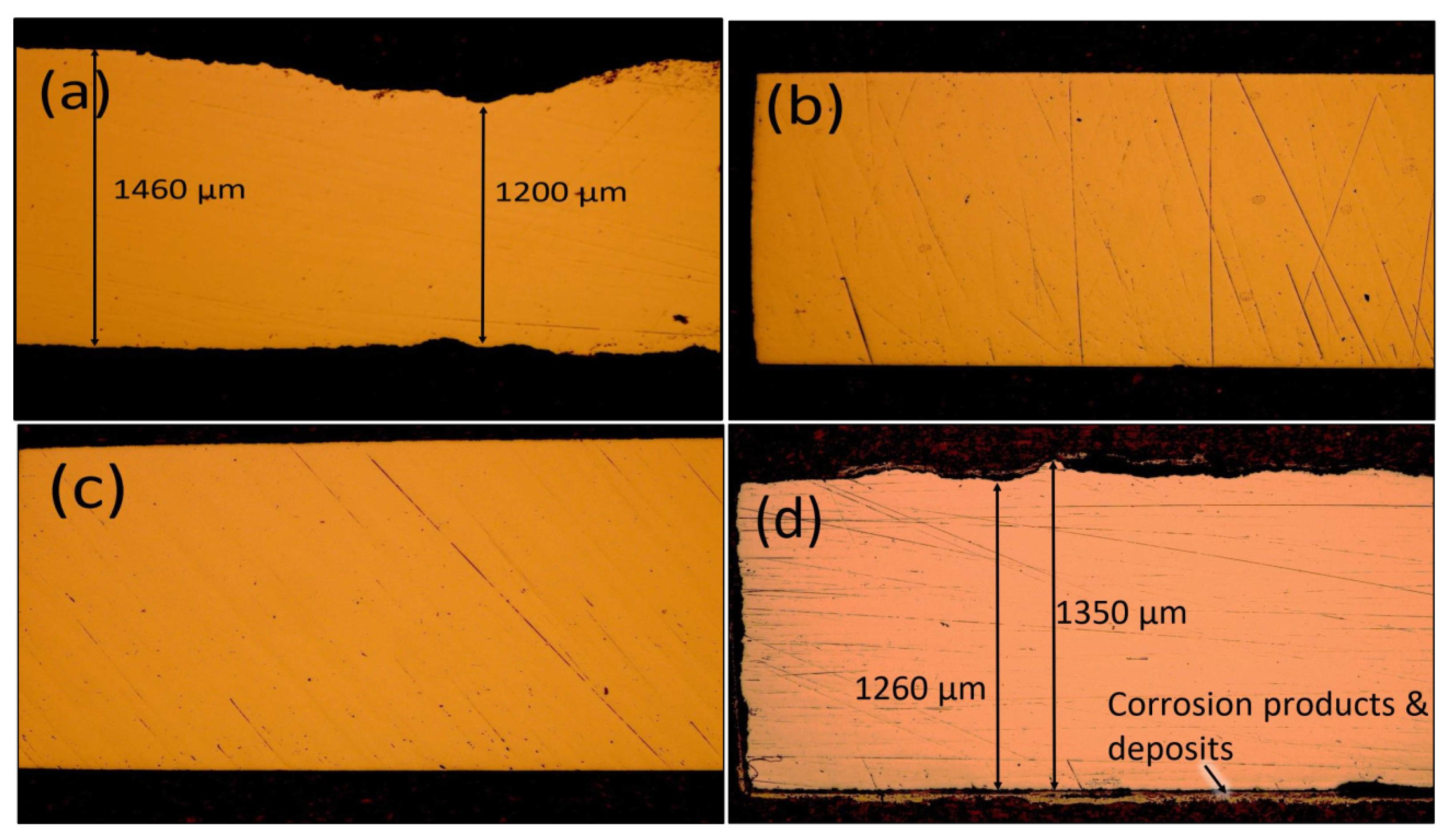
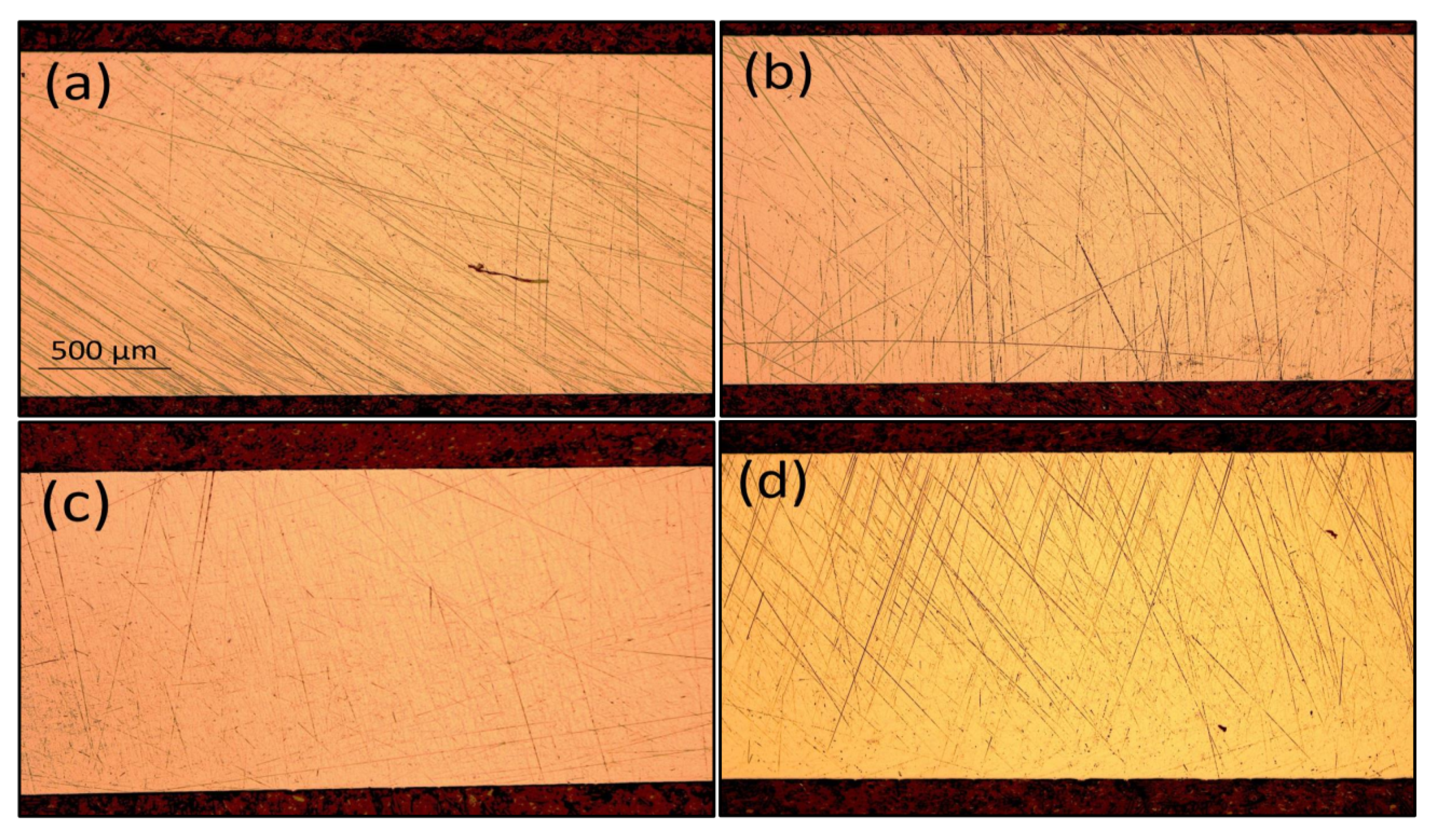
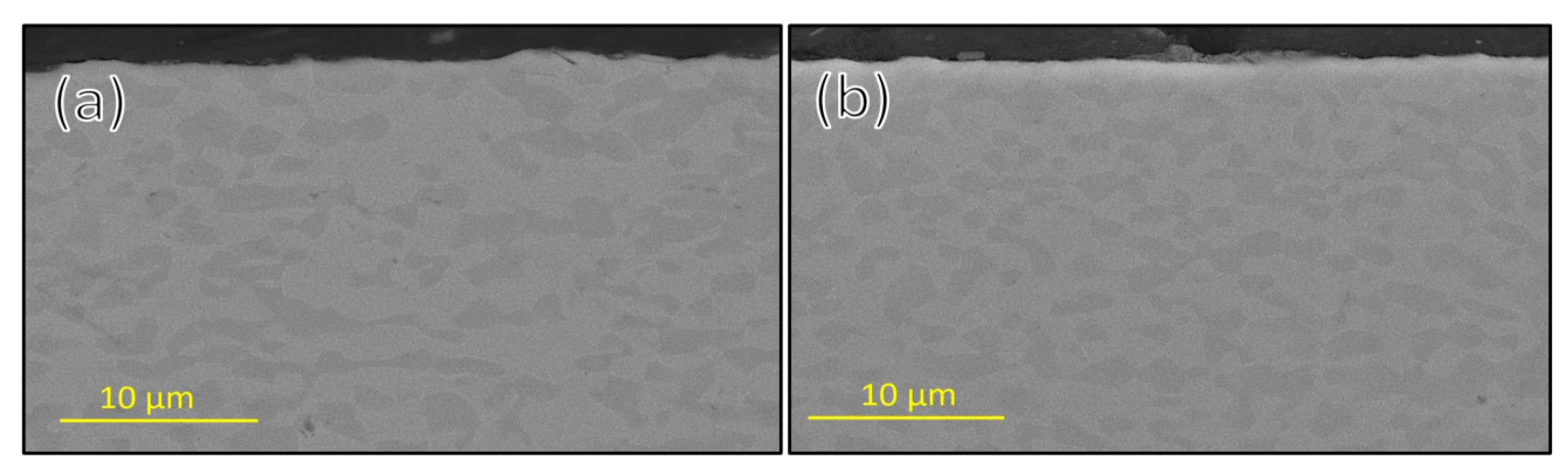
Further visual inspection of the carbon-steel samples after the corrosion testing indicated that some corrosion had occurred on sample 1 at the inlet of the first reactor and sample 9 at the outlet of the third reactor. This observation was evident from the bulk mass removal effect and pitting on the surface; a lower corrosion effect was observed on the samples between these two samples. This observation was strengthened under an optical microscope where the thickness reduction was apparent in a cross-sectional view of the first and last sample in comparison with other samples tested as can be seen in Figure 4.
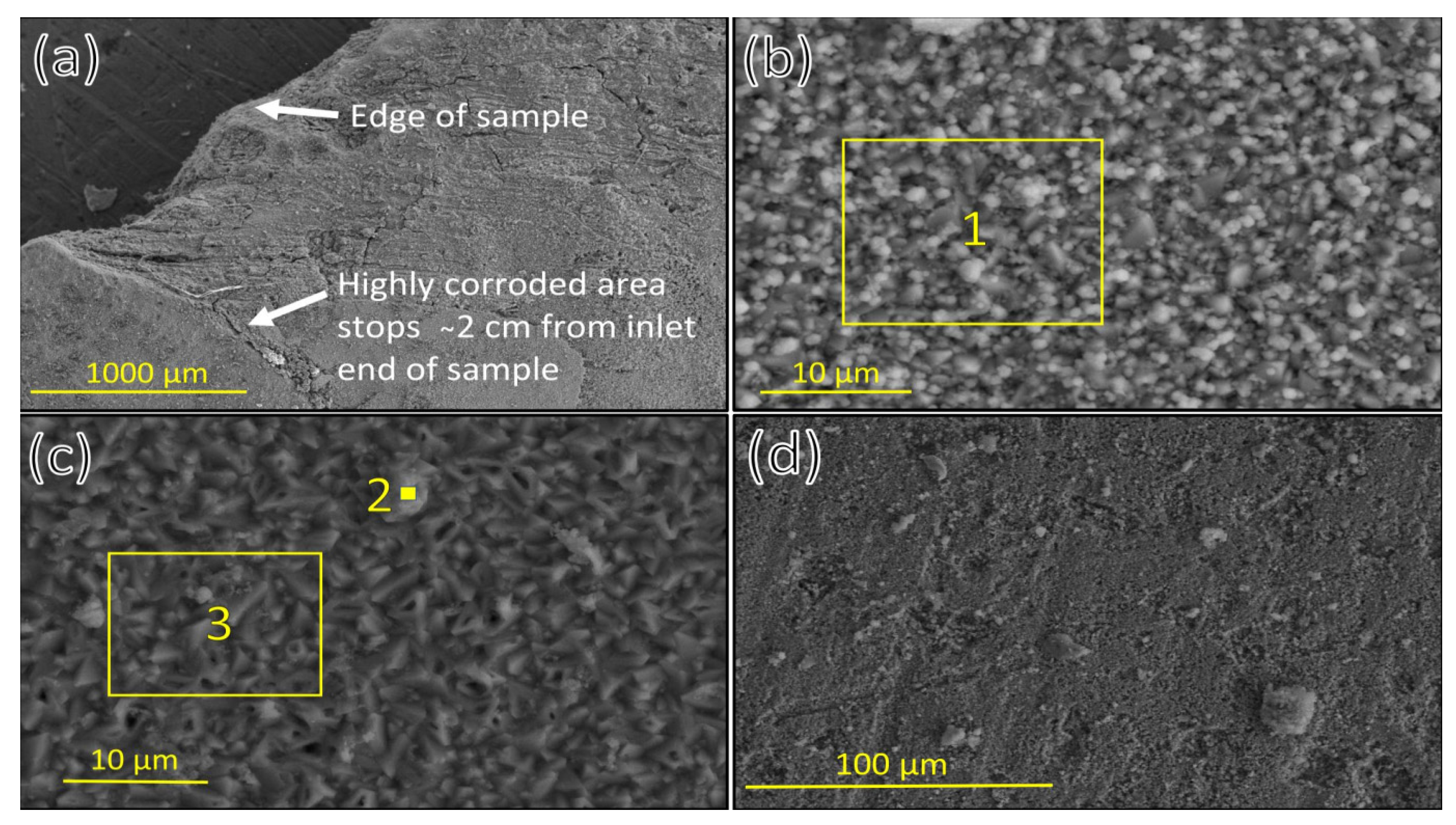
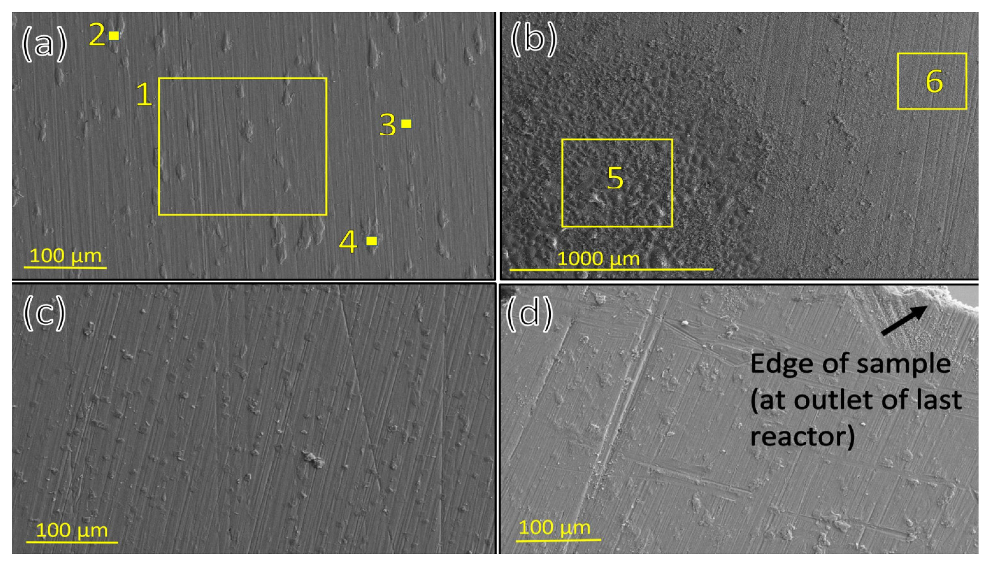
A surface analysis of all the carbon-steel samples showed that corrosion to some extent had occurred on the first few centimetres of sample 1 and sample 9. The first 1 to 2 cm of sample 1 had been prone to apparent corrosion, where part of the samples had been corroded away during the test. The corrosion observed on sample 9 had more micropitting texture rather than bulk mass removal. The samples in between had, to a large extent, surface texture similar to the surface texture characterized by the presence of magnetite (see Figure 5 and Table 6). This had been observed in other corrosion tests performed in the same testing equipment (but with different setup) in a superheated environment done by Thorhallsson et al. [15]. A broad range of corrosion forms was observed on the carbon-steel sample in the first few centimetres of sample 1: some locations had negligible oxide film observed on the surface; other locations had a dense oxide film present.
These findings might indicate that wet (aqueous) corrosion could have occurred at the first few centimetres and at the last centimetre in the testing volume because of boiling at the inlet and condensation at the outlet. Elemental analysis of carbon-steel samples indicated that some corrosion products from the fasteners or the reactor pipes (nickel-based alloy) had likely been transported to the surface of the corroded carbon-steel samples because Ni and Mo were sometimes observed on the corroded samples as seen in Figure 5 and Table 7 (and in Figure 4 and 
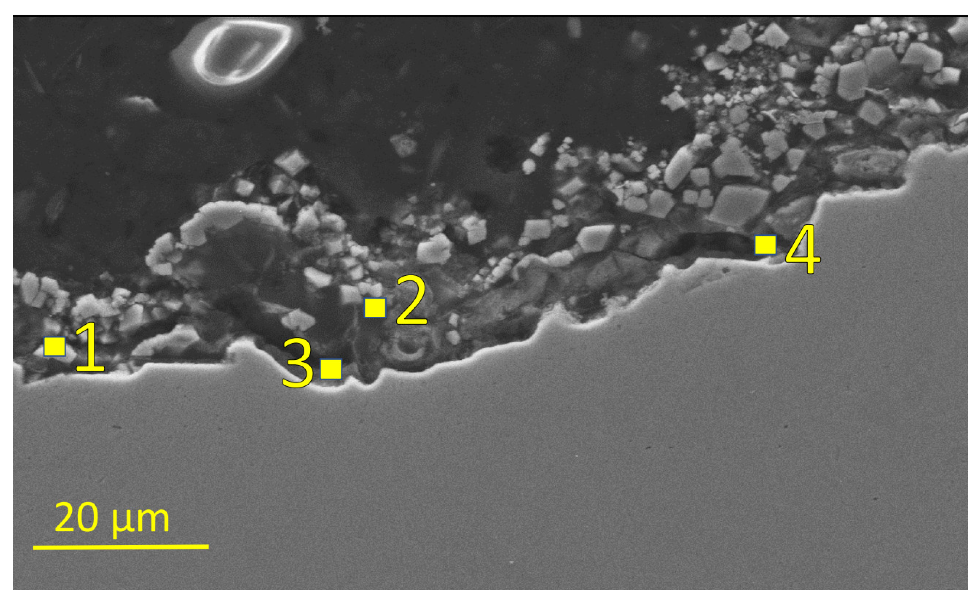
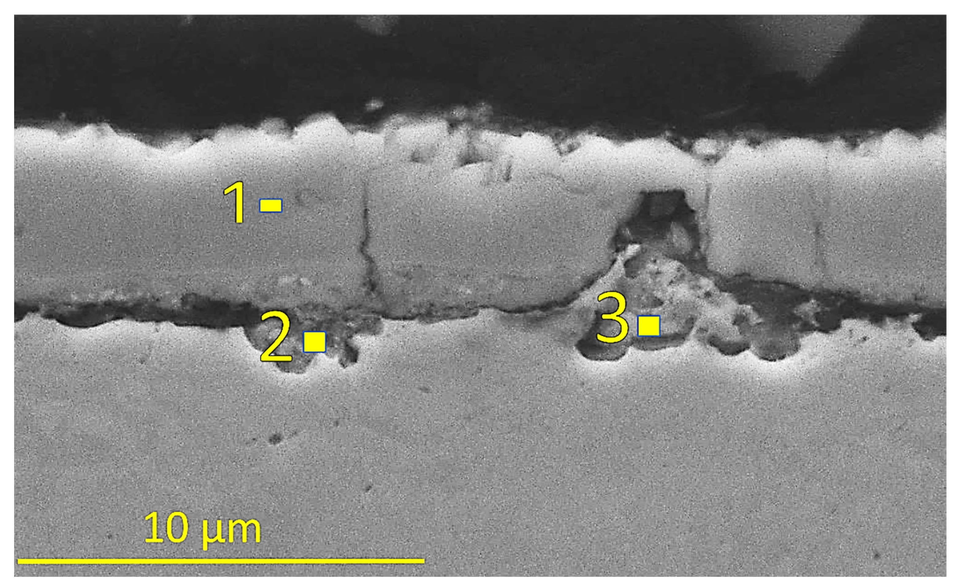
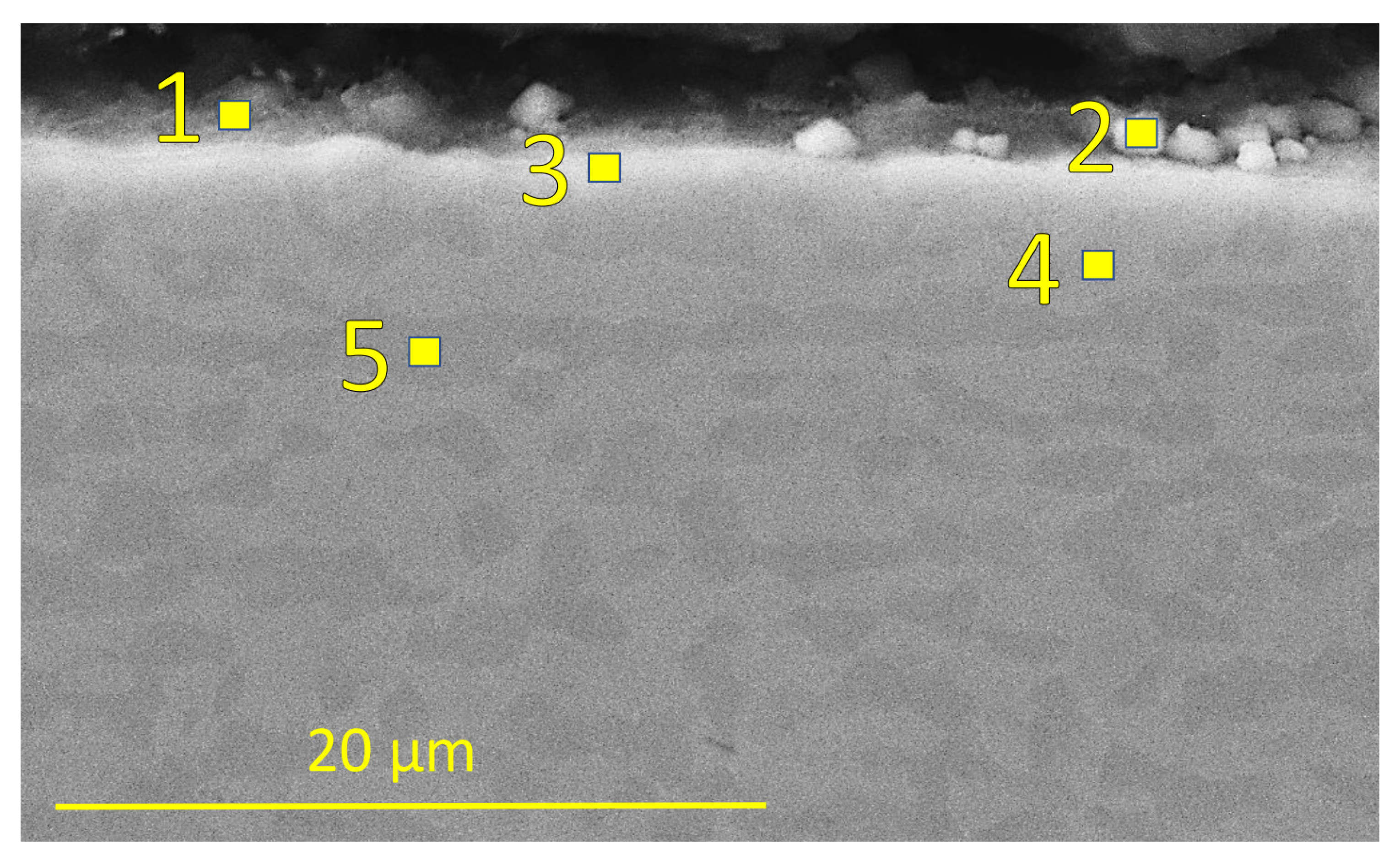
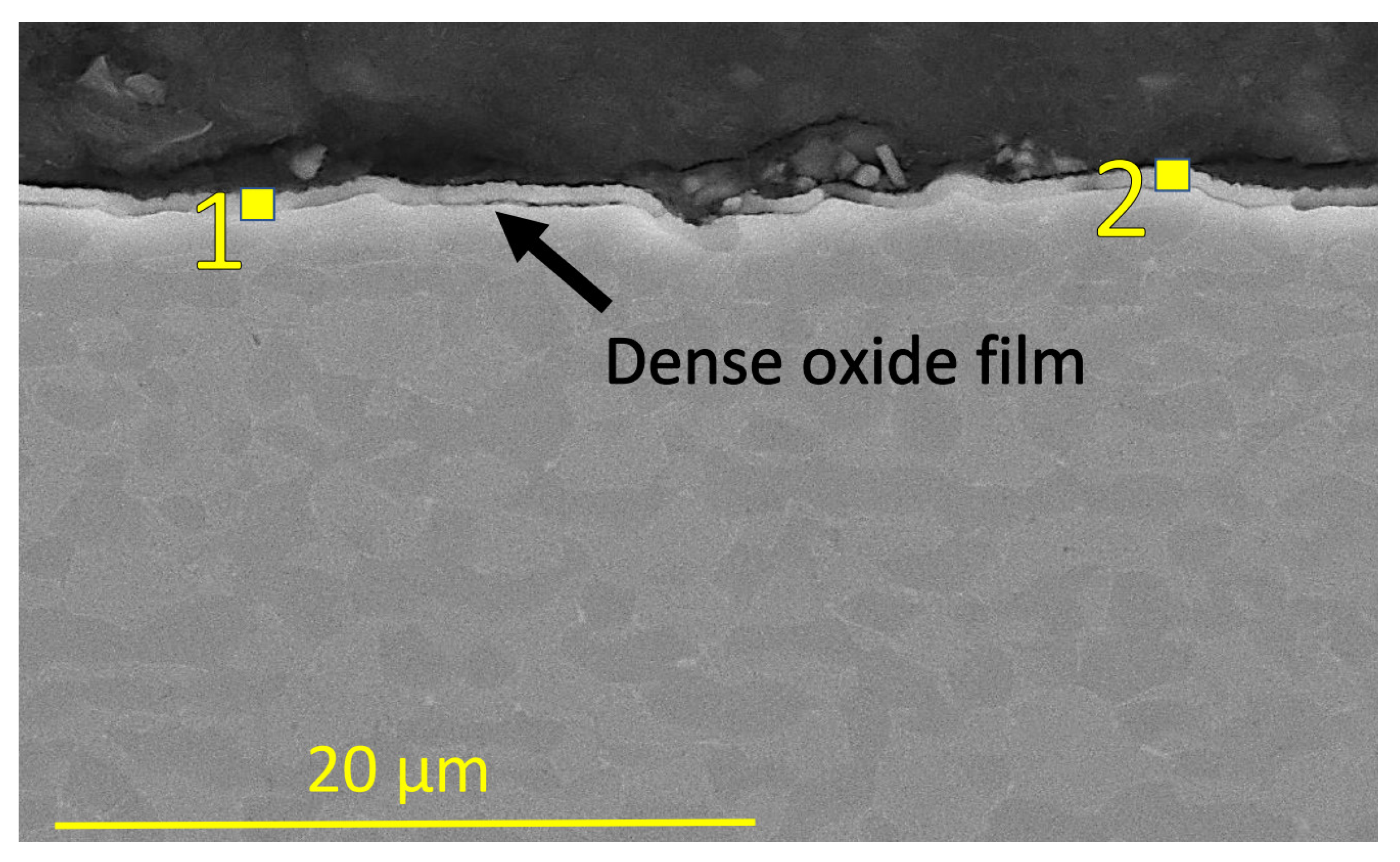
Table 6). When the cross-section of the samples in the three reactors was studied, some corrosion behaviour variability was observed: the first few centimetres of sample 1 had an incident of corrosion damage both where carbon-steel material residuals inside the corrosion film were observed on the sample (Figure 6 and 
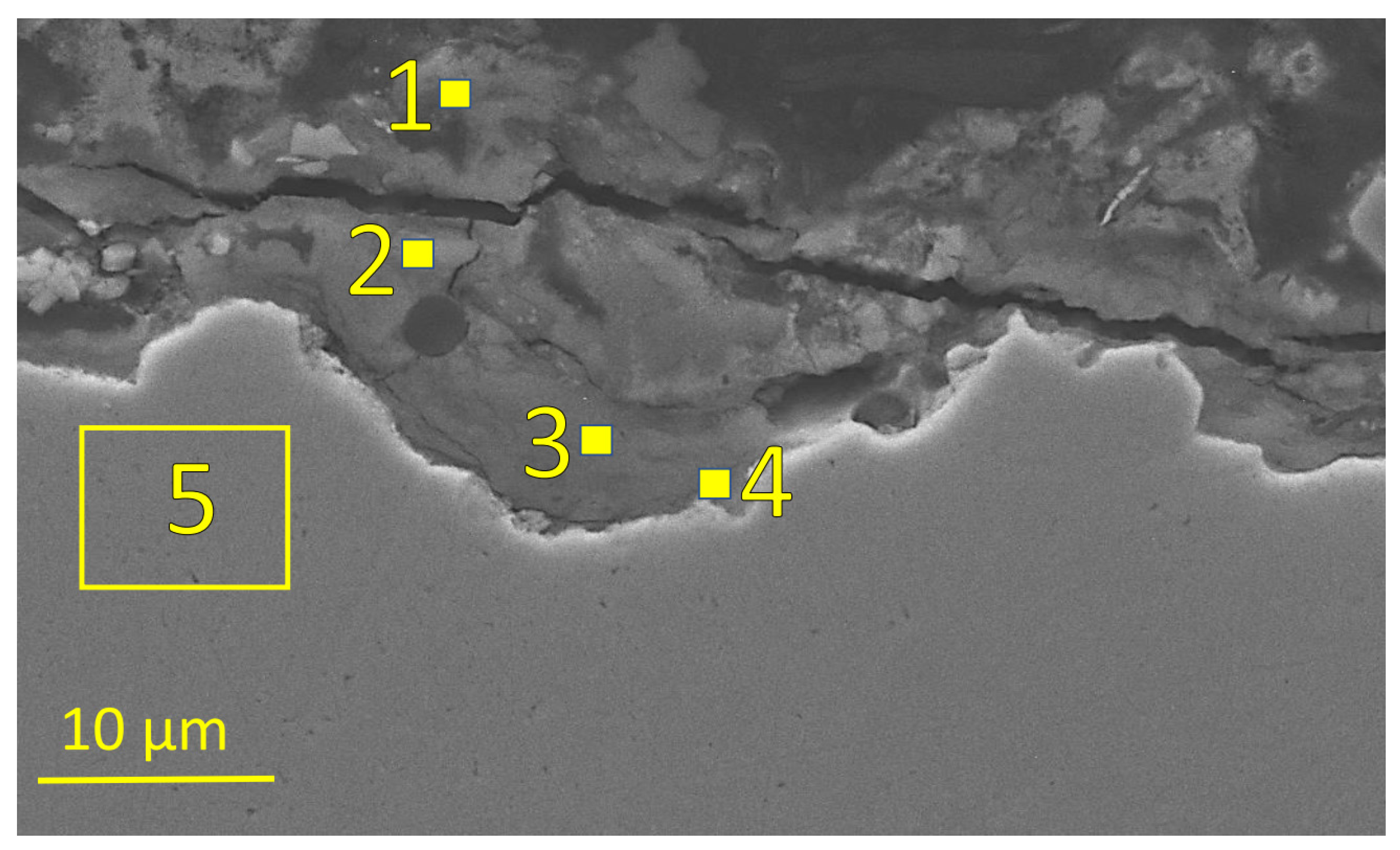
Table 7), and another incident where the thicker corrosion product (oxide film) was observed on the sample (Figure 7 and Table 8). The surface profile indicated in both cases that severe corrosion damage had occurred.
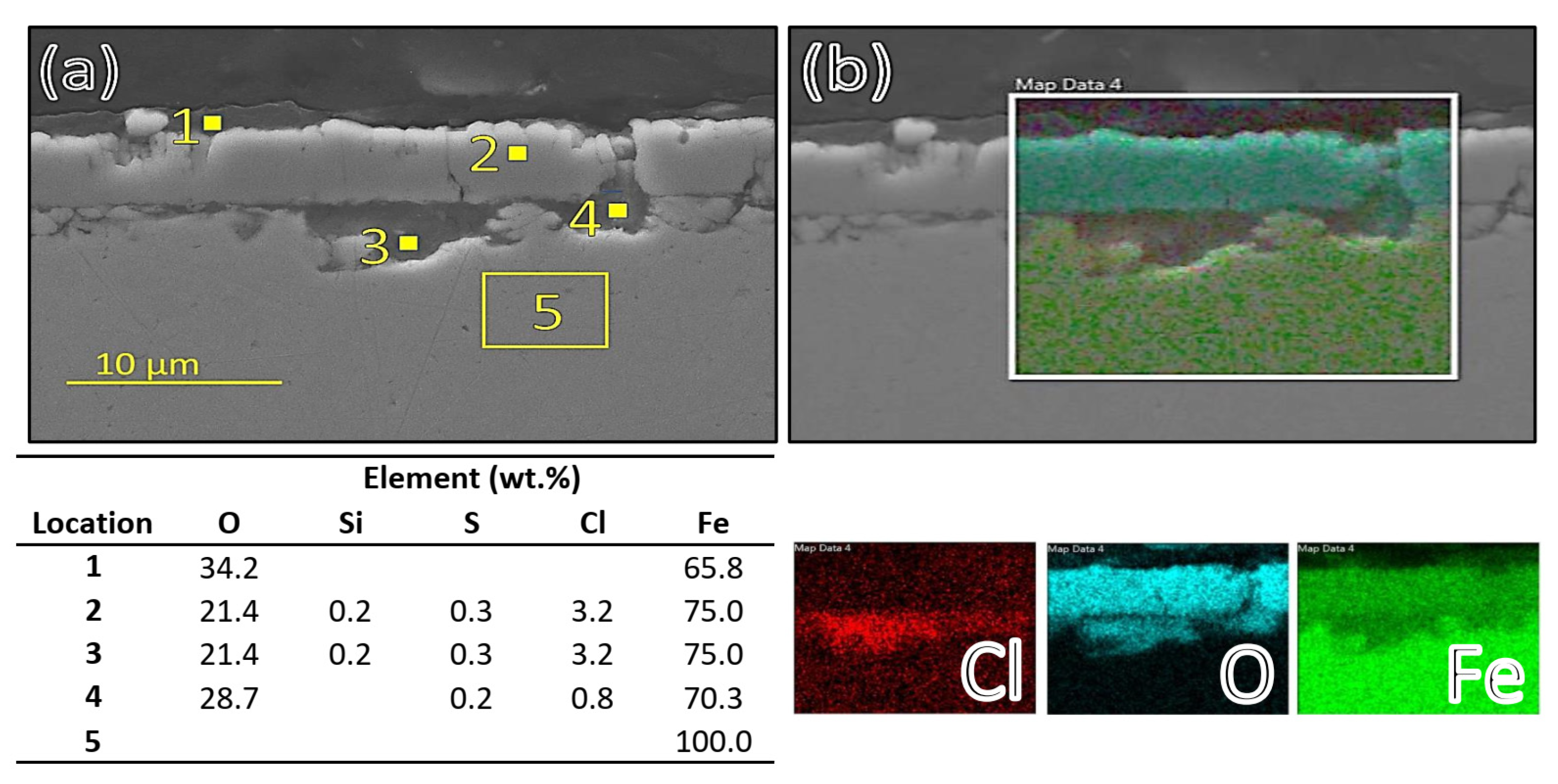
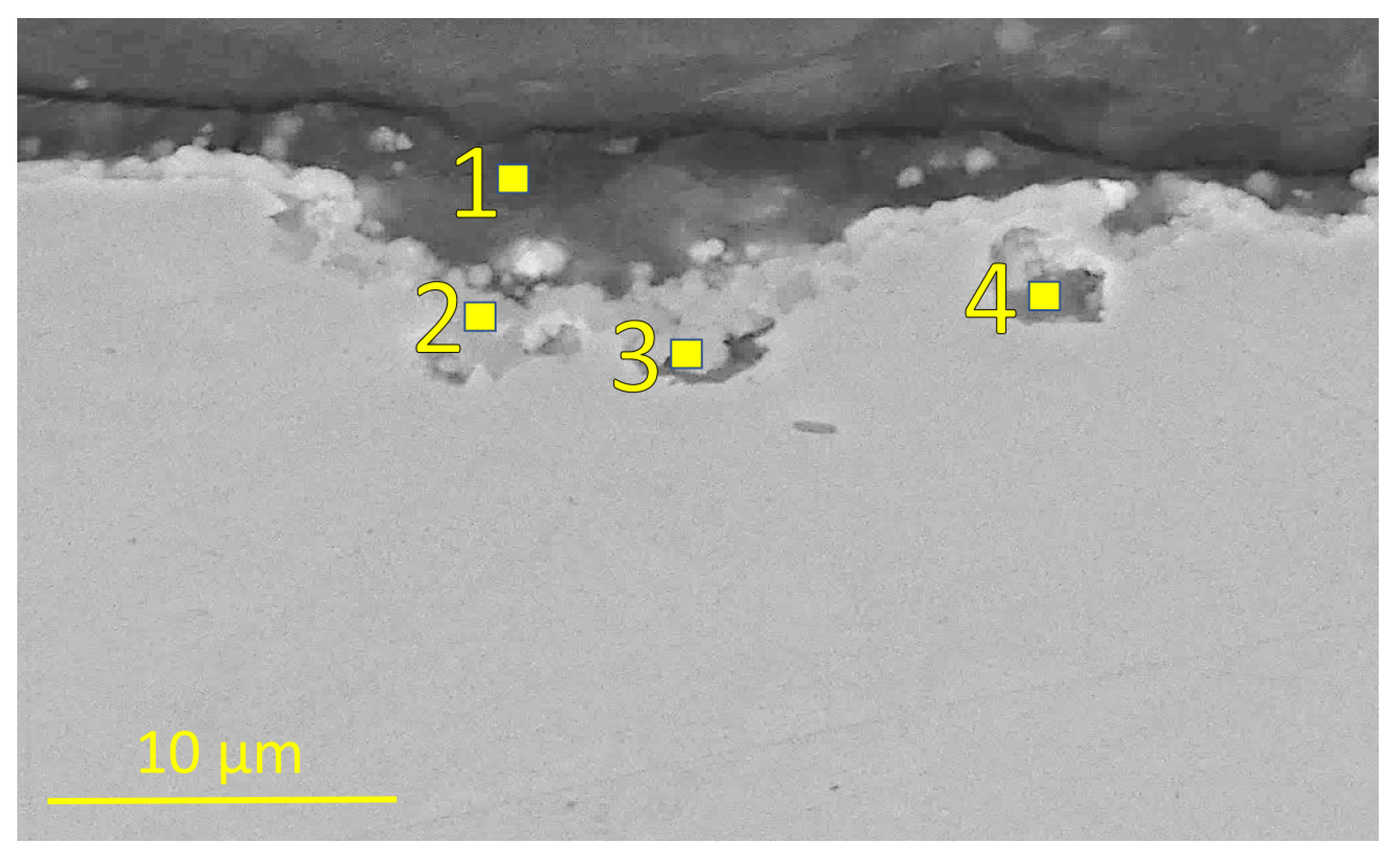
Further into the testing volume or 3 cm from the inlet of the first reactor, the form of the corrosion products changed to a more consistent or homogeneous texture, i.e., chloride rich pits under oxide film were observed more consistently than in the first 1 to 2 cm of sample 1 as can be seen in Figure 8.
These findings might indicate that the transition from acidic aqueous solution to vapour phase fluid occurred at the first few centimetres of sample 1. The corrosion of carbon steel in an acidic H2S environment at low and high temperatures showed that the carbon steel was prone to general and localized corrosion damage with an inner magnetite (Fe3O4) layer and outer iron sulphide layer in the corrosion film as reported by Gao et al. [30,31,32] in an aqueous environment. A study by Choi et al. showed that H2S can have an inhibiting effect on the corrosion of carbon steel in an acidic CO2/H2S environment at 25 °C [33], and Mursalov addressed the multifactor dependence and complexity of corrosion of H2S in an acidic environment [34]. The lack of an observed sulphide layer in our testing in the first few centimetres of carbon-steel sample 1 might have been due to the very high acidity of the testing fluid, which dissolved the sulphide layer, or to the high concentration of sodium chloride deposits on the corrosion samples that prevented sulphide formation by forming a mass transfer barrier at the surface when the testing fluid boiled in the first few centimetres of the first reactor. Furthermore, the kinetics of iron sulphide layer formation is slow in comparison to those of magnetite formation as concluded by Gao et al. [31]. In the sulphide layer formation process, magnetite layer forms first and iron sulphide then forms gradually in an acidic H2S environment at 120 °C. The lack of sulphide film in the first few centimetres of sample 1 could, therefore, have been due to the synergistic effect of slow sulphide-formation kinetics, or to the effect of an enriched concentration of corrosive species and salt deposits on the surface due to boiling of the testing fluid in the first few centimetres of sample 1. The stability of iron sulphide layers, summarized by Gao et al. [31], showed that the stability of the sulphides was reduced significantly below pH = 4 and was dependent on the reduction potential of the environment. In light of our testing results, low pH = 3 in our testing environment, and the lack of an iron sulphide layer in the corrosion product film, it was likely that the iron sulphide(s) corrosion products were not stable in the aqueous testing environment in the first few centimetres in the first reactor. A low concentration of sodium chloride was, however, detected in the corrosion products in the first few centimetres of sample 1. It likely occurred after the testing period because of the flushing of deionized water through the testing volume after the testing period (to prevent acidic condensation at high temperatures) and before the samples were removed from the reactor. The sodium chloride deposited due to boiling likely dissolved in the flushing water after the testing period and was flushed away with the deionized water through the testing volume at the end of the experiment. The loss of material and the lack of corrosion film on the surface in the first few centimetres of sample 1 indicated that the acidic aqueous solution at high temperature caused the removal of the corrosion products at a rapid rate. The results also indicate that, further into the first reactor, the fluid became less corrosive and the corrosion behaviour trended towards a more localized corrosion attack, as observed in previous study by Thorhallsson et al., for materials tested in superheated conditions [15]. The corrosion behaviour observed for carbon-steel sample 5 in the second reactor resembled the corrosion behaviour observed for sample 1 after the first few centimetres. The exception was that less chloride was detected in the pits in sample 5 in the second reactor and in sample 8 in middle of the third reactor, as seen in Figure 9, Table 9 and Figure 10 and Table 10, respectively.
This might also have indicated that the less non-volatile NaCl by-products were transported further into the testing volume. The corrosion products in the superheated testing volume (second reactor) did have a small concentration of sulphide corrosion products or a sulphide-rich layer which Thorhallsson et al. saw to a greater extent in the previous test [15]. This difference in the extent of sulphide formation could have been attributed to a shorter test period of the carbon steel, i.e., three days of testing in this study compared to 10 days in the previous testing. This observed difference in corrosion behaviour might indicate that the formation of the sulphide layer is a slow process in the superheated fluid containing H2S.
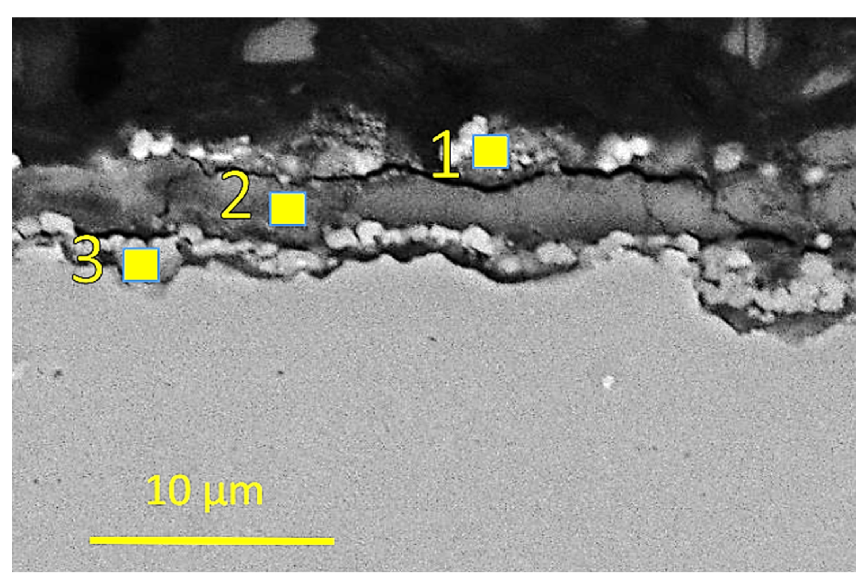
The corrosion behaviour of the carbon steel started to change again in the last sample in the third reactor where the set temperature was 180 °C. The corrosion in sample 9, three centimetres from the outlet, had a corrosion film with multiple layers. In comparison with samples 2–8, some sulphur was detected in the corrosion layers of sample 9, three centimetres from the outlet as seen in Figure 11 and Table 11.
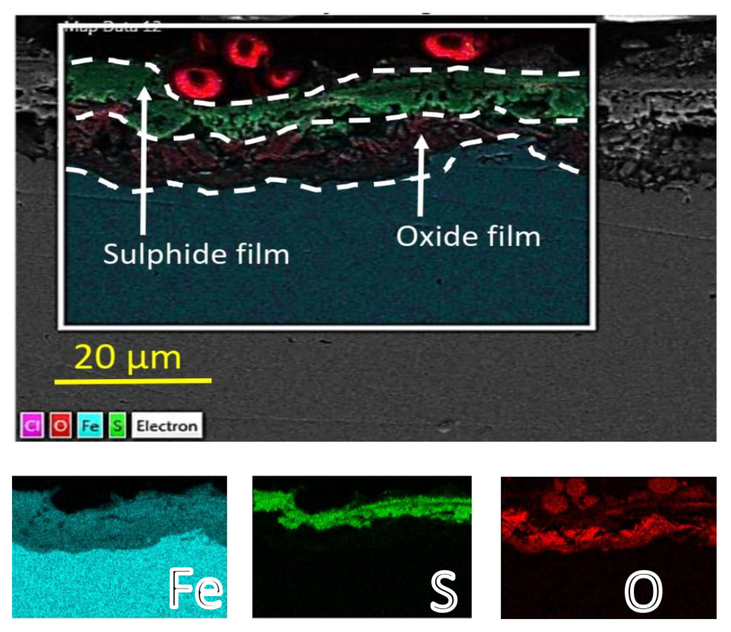
The transition to multiple-layer corrosion film behaviour became more apparent in the last centimetre of sample 9 in the third reactor. A sulphide-rich outer layer and an oxygen-rich sublayer formed, which was in an agreement with other study results of H2S corrosion of carbon steel in an aqueous environment at high temperatures [30,31] (See Figure 12).
The difference between the corrosion products observed on the carbon steel in the first few centimetres of sample 1 in the first reactor (where the boiling of the testing fluid likely occurred) and those of sample 9 in the last reactor (where condensation of the testing fluid occurred) could be due to different pH conditions and the concentration of the corrosive species (HCl, H2S and CO2) in the testing fluid. The effect of the deposited NaCl by-product in the boiling and NaCl enrichment in the testing fluid in the first few centimetres of the first reactor was also another factor that likely affected the corrosion mechanism, which led to different corrosion behaviour in the testing volume, where boiling and condensation presumably occurred.
The same test setup was applied to testing the titanium-alloy samples. The appearance of the cross-section of the titanium-alloy samples after testing indicated that no corrosion damage was experienced as seen in Figure 13.
Microstructural and chemical analysis in the SEM with XEDS confirmed the optical microscopy result: no corrosion damage was observed in any of the titanium-based samples tested. Some sulphur deposits were analysed on the surface of the samples and some corrosion products from the washers and the fastener/tubing in the testing equipment, but no indication of localized corrosion damage or general corrosion was observed. A denser oxide layer was observed in sample 5 in the superheated testing volume, indicating that the kinetics of TiO2 film growth on the surface could be a temperature-dependent mechanism even though the titanium oxide growth rate was constant at high temperatures as reported by Kumagai et al. [35]. Microstructural and elemental analysis of both surface and the cross-section of the titanium alloy samples can be seen in Figure 14 (with Table 12), Figure 15 (with Table 13), Figure 16 (with Table 14) and Figure 17. Titanium and titanium alloys are known to perform well in various corrosive environments [36,37], which is consistent with results observed in this study.

3.2. Weight Loss Analysis

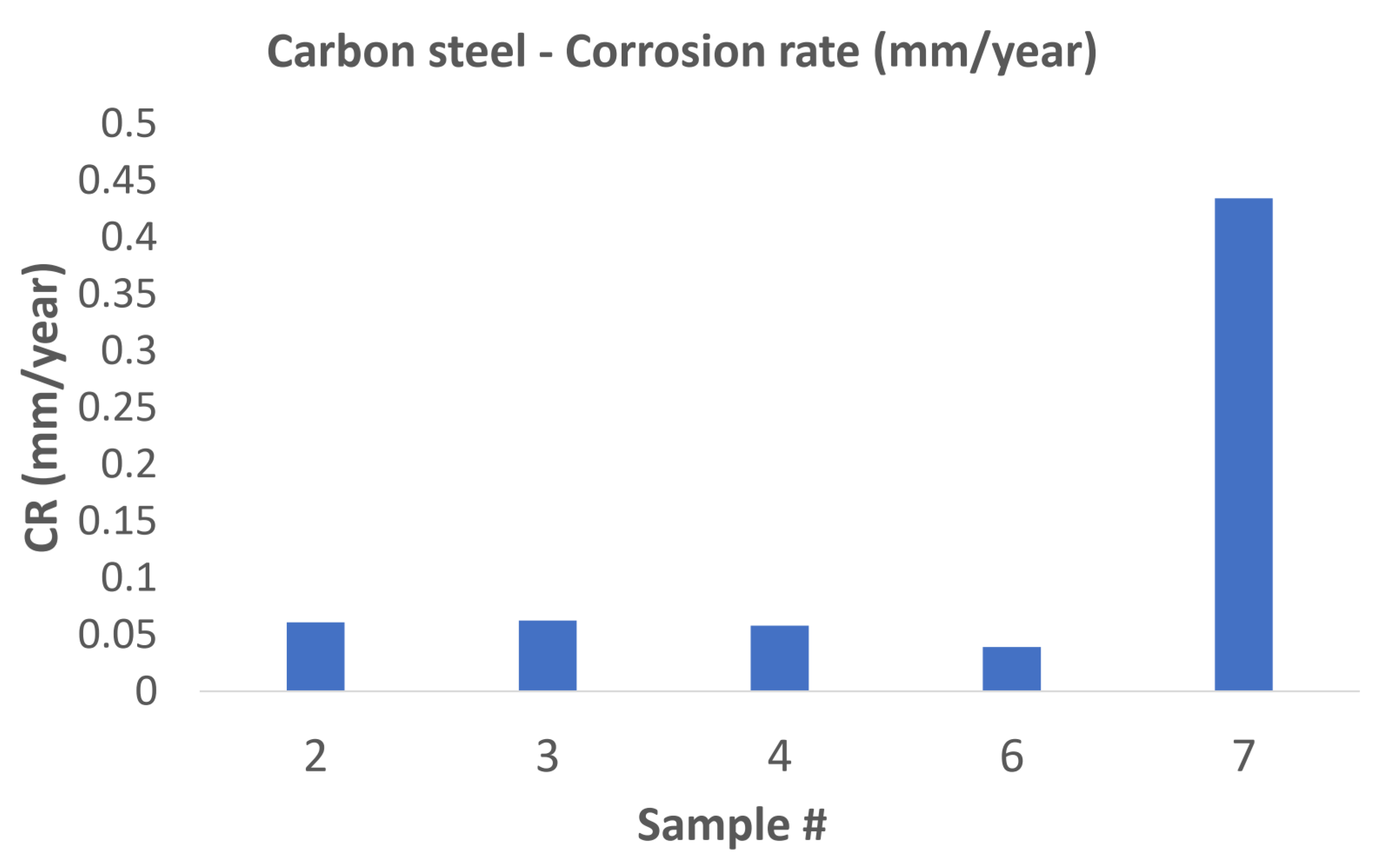
Samples 2, 3, 4, 6, and 7 were used for weight-loss analysis for the tested carbon-steel material. The weight loss, and hence the calculated corrosion rate in the samples accommodated in the first and second reactors, had a corrosion rate of the same order of magnitude as the carbon steel tested in a superheated environment in a study by Thorhallsson et al. [15]. The first sample in the third reactor had a corrosion rate an order of magnitude higher than all other weight loss samples in the first and second reactor as can be seen in Figure 18. The increased corrosion rate of sample 7 in the third reactor might indicate that condensation of the testing fluid started at the inlet of the 3rd reactor, resulting in rapid electrochemical corrosion.
As described earlier, the titanium-alloy samples were only cleaned by ethanol in an ultrasonic bath due to the extremely adherent titanium oxide film that formed. Samples 2 and 3 in the first reactor, sample 4 and 6 in the second reactor and samples 7 and 8 in the third reactor were used for weight-loss analysis. Only a negligible weight gain was observed for all the titanium samples except for sample 8, which had a weight loss of 0.001 mm/year, which was insignificant. The weight gain of titanium alloys, however, was well known due to the growth of the titanium dioxide film during exposure.

3.3. XRD Analysis

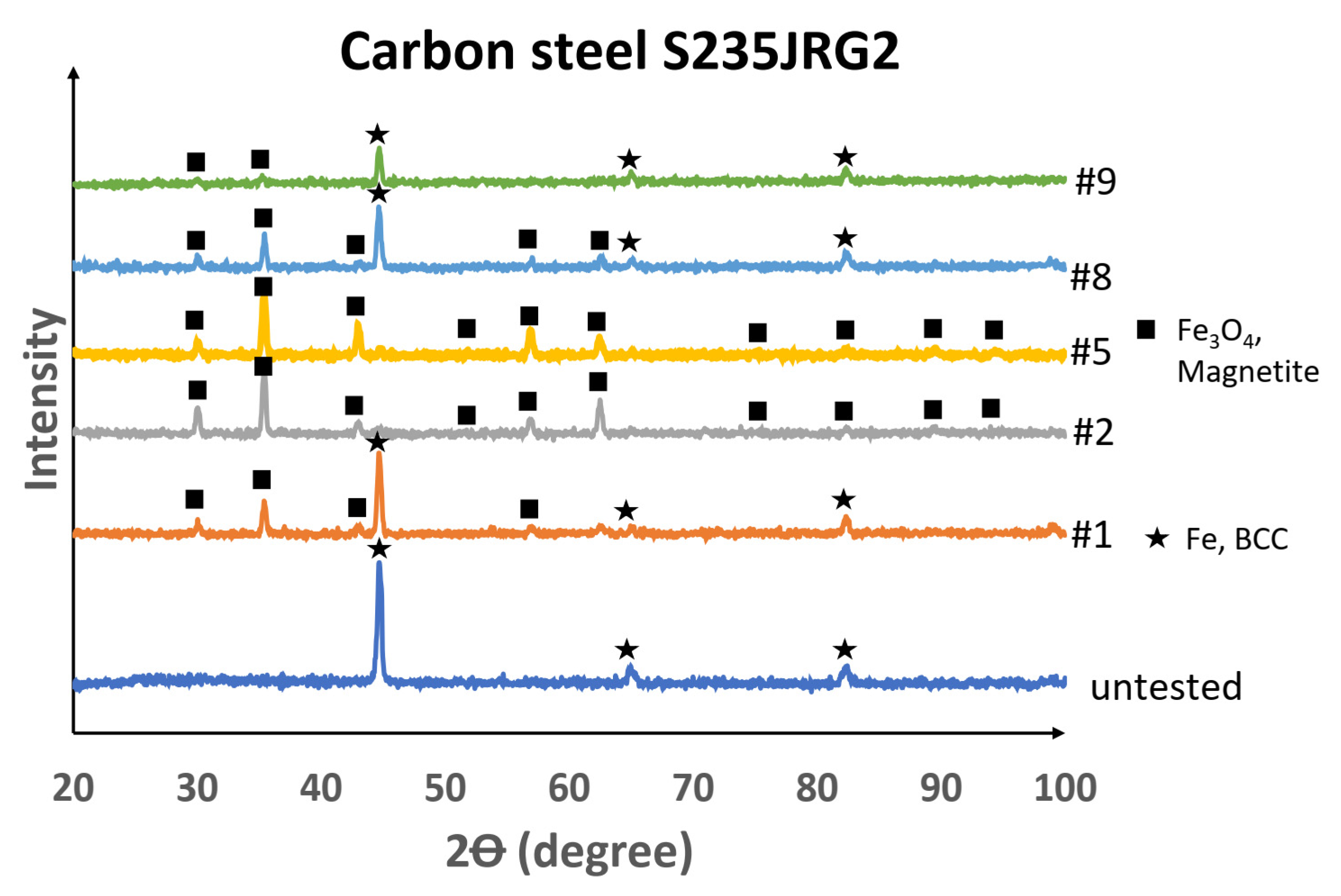
It was necessary to evaluate the XRD results of the untested and corrosion-tested carbon steel in connection with the state of the fluid and with the SEM and XEDS results, which showed that the liquid state or condensation of the testing fluid occurred at the inlet of the first reactor (sample 1) and in all the volume of the third reactor (sample 9). From the XRD pattern of the surface of sample 1, the crystalline phases detected were the body-centred cubic (BCC) system with iron (Fe) and the cubic crystal system with iron oxide in the form of magnetite (Fe3O4). The samples in the proposed superheated testing volume, samples 2–5, had magnetite detected on the surface, but in sample 8 the transition from magnetite as a surface covering to an exposed BCC–Fe bulk material likely occurred. Sample 9 then had peaks of BCC–Fe crystal structure identified. From the Pourbaix diagram of iron at high temperatures [38], it was concluded that magnetite is not stable or present in an acidic (pH < 4) aqueous solution. Since the peaks for magnetite were not present in the XRD pattern for samples 1 and 9, it further strengthened the conclusion that acidic, aqueous conditions were present in the testing volume where sample 1 and sample 9 were located. Weak magnetite scattering from sample 8 indicated that the extent of acidic condensation (condensate) was likely less on sample 8 in comparison with sample 9. The XRD patterns of the untested and tested carbon-steel samples are shown in Figure 19.
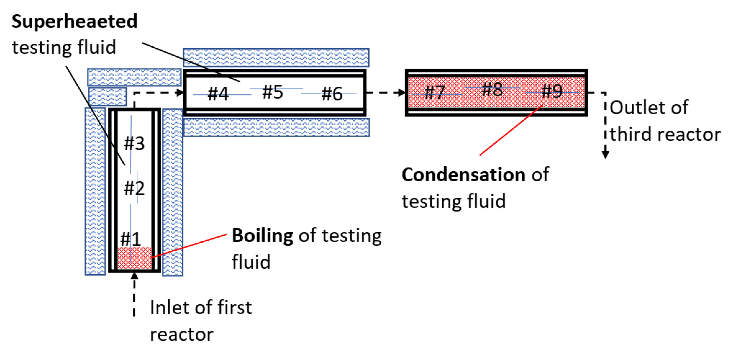
From the microstructural, weight-loss and XRD analysis of the carbon steel, it was concluded that the testing fluid was likely in a two-phase state at the first few centimetres in the inlet of the first reactor and in a two-phase state or condensing condition in the third reactor. The results indicated that the testing fluid was in a superheated state in the testing volume between the two-phase volumes as illustrated in Figure 20.
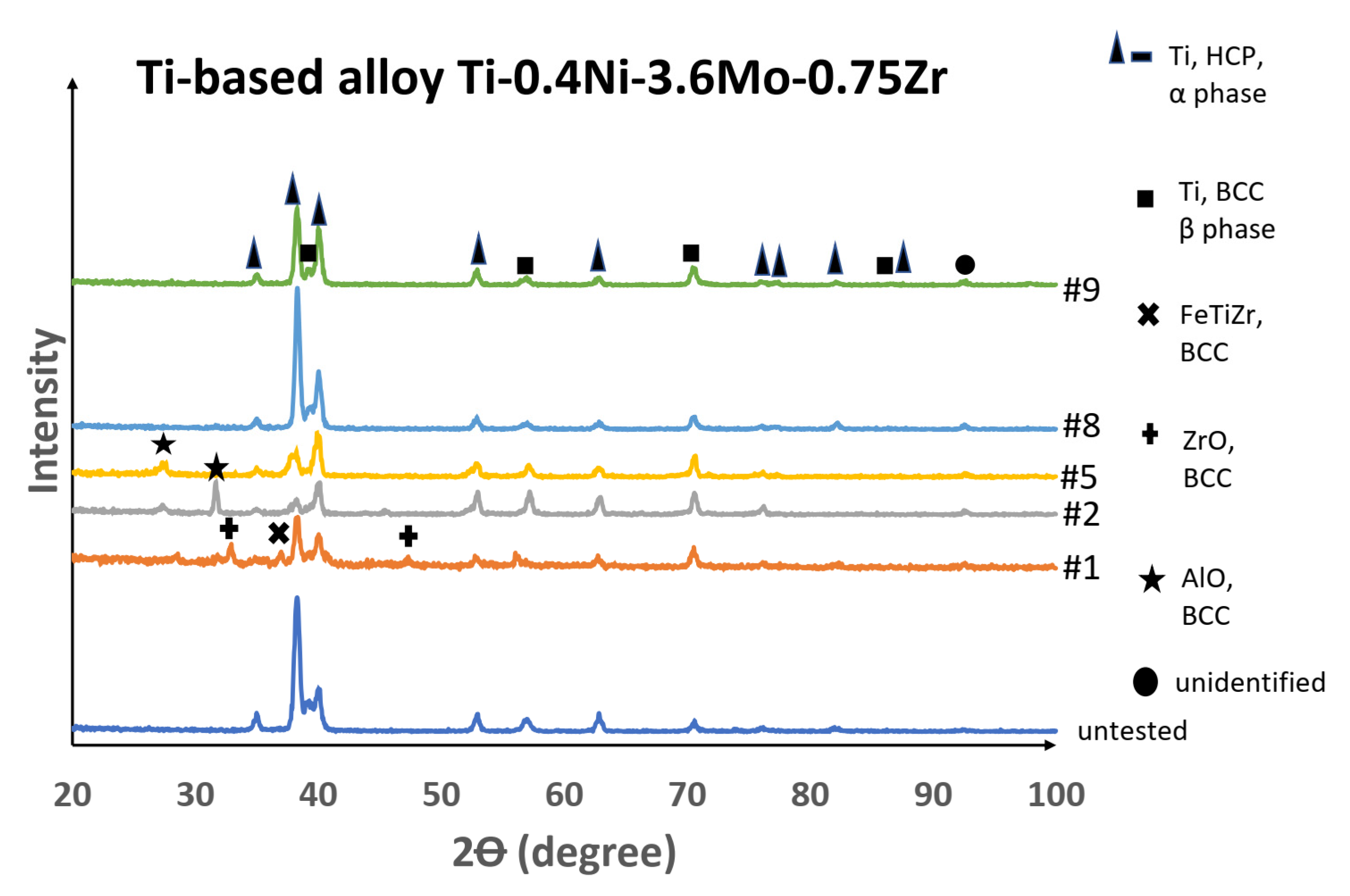
The XRD results of the surface of the titanium alloy samples showed little difference in crystal structure for the tested sample in comparison with the untested sample. Some changes were observed for sample 1 (a zirconium oxide crystal structure), which was not detected in other samples. Alumina oxide–BCC phase was detected on samples 2 and 5, which was likely due to corroded alumina oxide washers’ being transported to the samples. The XRD result for the tested titanium alloy samples was in good agreement with the results from the SEM and XEDS analysis, i.e., an insignificant corrosion effect as illustrated in Figure 21.

4. Conclusions

Carbon steel and titanium-alloy were tested in a simulated, high-temperature geothermal environment. From the corrosion testing of the carbon steel, it was concluded that the testing fluid was at boiling conditions (two-phase) at the first few centimetres of reactor 1 where sample 1 was situated, at superheated (single-phase) conditions in the testing volume accommodating samples 2–6 and at condensation (two-phase) conditions at samples 7–9. The low carbon steel, S235JRG2, was prone to general and localized corrosion damage in the testing volume where boiling and condensation occurred, i.e., the two-phase state of the testing fluid. Mixed corrosion products (oxides, sulphides and chlorides) were observed in the sample at boiling locations. The oxide corrosion layer was dominant on the samples in the superheated testing volume, and sulphides with an oxide sublayer were observed on the samples in the testing volume where condensation occurred. A dissimilar corrosion behaviour of carbon steel in the testing volume where boiling and condensation occurred could have been attributed to the effect of sodium chloride brine deposits that formed in the boiling process, or to different mass-removal transport phenomena due to availability of aqueous testing fluid and the barrier effect of the sodium chloride brine. The lack of sulphide layer formation on the oxide layer on the surface of the sample in the superheated testing volume could have been due to the slow kinetics of sulphide formation. The titanium alloy, Ti-0.4Ni-3.6Mo-0.75Zr (Ti-475) was not prone to corrosion where the testing fluid was in a single superheated or two-phase testing volume. This alloy could therefore be a promising candidate as a geothermal casing material in a high-temperature, corrosive, geothermal environment where single- or double-phase conditions with high brine and acidic concentrated conditions are expected.

Author Contributions

Conceptualization, A.I.T. and S.N.K.; methodology, A.I.T. and S.N.K.; software, A.I.T.; formal analysis, A.I.T.; investigation, A.I.T.; resources, A.I.T.; data curation, A.I.T.; writing-original draft preparation, A.I.T.; writing—review and editing, A.I.T. and S.N.K.; visualization A.I.T. and S.N.K.; supervision, S.N.K.; project administration, S.N.K.; funding acquisition, S.N.K.; All authors have read and agreed to the published version of the manuscript.

Funding

The authors would like to thank the Icelandic Research Fund (RANNÍS) grants No. 163108-051, 163108-052 and 163108-053, Geothermal Research Group (GEORG) and Energy Research Fund (Landsvirkjun) for funding this project.

Data Availability Statement

The raw/processed data required to reproduce these findings cannot be shared at this time as the data also forms part of an ongoing study.

Acknowledgments

The authors would like to give gratitude to employees at Innovation Center of Iceland (ICI) and employees at Grein Research for their technical assistance. The authors would also like to give gratitude to Titanium Metals Corporation (TIMET) for collaboration and providing titanium samples for the testing.

Conflicts of Interest

The authors declare no conflict of interest.

References

  1. Thomas, R. Titanium in the geothermal industry. Geothermics 2003, 32, 679–687. [Google Scholar] [CrossRef]
  2. Syrett, B.C.; Macdonald, D.D.; Shih, H. Pitting resistance of engineering materials in geothermal brines—I. Low salinity brine. Corrosion 1980, 36, 130–139. [Google Scholar] [CrossRef]
  3. MacDonald, W.D.; Grauman, J.S. Exposure testing of UNS R53400, R56404 and N06625 in simulated salton sea geothermal brine. In Proceedings of the NACE-2018-11547, Phoenix, AZ, USA, 15–19 April 2018; p. 9. [Google Scholar]
  4. Faes, W.; Lecompte, S.; Ahmed, Z.Y.; Van Bael, J.; Salenbien, R.; Verbeken, K.; De Paepe, M. Corrosion and corrosion prevention in heat exchangers. Corros. Rev. 2019, 37, 131–155. [Google Scholar] [CrossRef]
  5. Carter, J.P.; McCawley, F.X. Corrosion tests in brine and steam from the Salton Sea KGRA. J. Mater. Energy Syst. 1982, 3, 30–38. [Google Scholar] [CrossRef]
  6. Grauman, J.S. Titanium—Properties and applications for the chemical process industries. Encycl. Chem. Process. Des. 1998, 58, 123–147. [Google Scholar]
  7. Schutz, R.W.; Wardlaw, T.L.; Hall, J.A. Ti-CODE 12—An improved industrial alloy. In Proceedings of the Anniversary Conference of the Japan Titanium Society, Kobe, Japan, 15–18 November 1982. [Google Scholar]
  8. Abdel-Hady, M.; Fuwa, H.; Hinoshita, K.; Kimura, H.; Shinzato, Y.; Morinaga, M. Phase stability change with Zr content in β-Type Ti-Nb alloys. Scr. Mater. 2007, 57, 1000–1003. [Google Scholar] [CrossRef]
  9. Zhou, Y.; Li, Y.; Yang, X.; Cui, Z.; Zhu, S. Influence of Zr content on phase transformation, microstructure and mechanical properties of Ti75-XNb25Zrx (x = 0–6) Alloys. J. Alloy. Compd. 2009, 486, 628–632. [Google Scholar] [CrossRef]
  10. Oliveira, N.T.C.; Ferreira, E.A.; Duarte, L.T.; Biaggio, S.R.; Rocha-Filho, R.C.; Bocchi, N. Corrosion resistance of anodic oxides on the Ti-50Zr and Ti-13Nb-13Zr alloys. Electrochim. Acta 2006, 51, 2068–2075. [Google Scholar] [CrossRef]
  11. Zhang, Y.; Davenport, A.J.; Burke, B.; Vyas, N.; Addison, O. Effect of Zr addition on the corrosion of Ti in acidic and Reactive Oxygen Species (ROS)-Containing environments. ACS Biomater. Sci. Eng. 2018, 4, 1103–1111. [Google Scholar] [CrossRef]
  12. Nogara, J.; Zarrouk, S.J. Corrosion in geothermal environment: Part 1: Fluids and their impact. Renew. Sustain. Energy Rev. 2018, 82, 1333–1346. [Google Scholar] [CrossRef]
  13. Nogara, J.; Zarrouk, S.J. Corrosion in geothermal environment: Part 2: Metals and alloys. Renew. Sustain. Energy Rev. 2018, 82, 1347–1363. [Google Scholar] [CrossRef]
  14. Karlsdottir, S.N. Corrosion, Scaling and Material Selection in Geothermal Energy Production. In Comprehensive Renewable Energy; Elsevier: Amsterdam, The Netherlands, 2012; pp. 239–256. ISBN 978-0-08-087872-0. [Google Scholar]
  15. Thorhallsson, A.I.; Stefansson, A.; Kovalov, D.; Karlsdottir, S.N. Corrosion testing of materials in simulated superheated geothermal environment. Corros. Sci. 2020, 168, 108584. [Google Scholar] [CrossRef]
  16. Ikeuchi, J.; Sanada, N.; Asano, O.; Kurata, Y.; Sata, N.; Nanjo, N.; Ikeshoji, T.; Okahara, Y. Corrosion behavior of materials in various geothermal environments. J. Electrochem. Soc. 1987, 134, C423. [Google Scholar]
  17. Culivicchi, G.; Palmerini, C.G.; Scolari, V. Behaviour of materials in geothermal environments. Geothermics 1985, 14, 73–90. [Google Scholar] [CrossRef]
  18. Karlsdottir, S.N.; Ragnarsdottir, K.R.; Thorbjornsson, I.O.; Einarsson, A. Corrosion testing in superheated geothermal steam in Iceland. Geothermics 2015, 53, 281–290. [Google Scholar] [CrossRef]
  19. Kritzer, P. Corrosion in high-temperature and supercritical water and aqueous solutions: A review. J. Supercrit. Fluids 2004, 29, 1–29. [Google Scholar] [CrossRef]
  20. Sarrade, S.; Feron, D.; Rouillard, F.; Perrin, S.; Robin, R.; Ruiz, J.-C.; Turc, H.-A. Overview on corrosion in supercritical fluids. J. Supercrit. Fluids 2017, 120, 335–344. [Google Scholar] [CrossRef]
  21. Liu, Z.; Gao, X.; Du, L.; Li, J.; Zheng, C.; Wang, X. Corrosion Mechanism of Low-Alloy Steel Used for Flexible Pipe in Vapor-Saturated H2S/CO2 and H2S/CO2-Saturated Brine Conditions. Mater. Corros. Werkst. Korros. 2018, 69, 1180–1195. [Google Scholar] [CrossRef]
  22. Yang, J.; Wang, S.; Li, Y.; Tang, X.; Wang, Y.; Xu, D.; Guo, Y. Effect of salt deposit on corrosion behavior of Ni-based alloys and stainless steels in supercritical water. J. Supercrit. Fluids 2019, 152, 104570. [Google Scholar] [CrossRef]
  23. Jonsson, T. Corrosion Testing in a Simulated High Temperature Geothermal Environment. Master’s Thesis, University of Iceland, Reykjavik, Iceland, 2015. [Google Scholar]
  24. Thorhallsson, A.I.; Karlsdottir, S.N.; Stefansson, A. Corrosion testing of uns n06625 in a simulated high temperature geothermal environment. In Proceedings of the NACE Corrosion Conference & Expo 2018, Phoenix, AZ, USA, 15 April 2018. [Google Scholar]
  25. Arnórsson, S. Isotopic and Chemical Techniques in Geothermal Exploration, Development and Use: Sampling Methods, Data Handling, Interpretation; Non-Serial Publications; International Atomic Energy Agency: Vienna, Austria, 2001; ISBN 92-0-101600-X. [Google Scholar]
  26. Felder, R.M.; Rousseau, R.W.; Bullard, L.G. Felder´s Elementary Principles of Chemical Processes; Wiley and Sons: Hoboken, NJ, USA, 2016. [Google Scholar]
  27. Wolfram. Wolfram Alpha Widgets; Wolfram Alpha LLC: Champaign, IL, USA, 2020. [Google Scholar]
  28. American Petroleoum Institute. API 5CRA—Specification for Corrosion Resistant Alloy Seamless Tubes for Use as Casing, Tubing and Coupling Stock; American Petroleoum Institute: Washington, DC, USA, 2015. [Google Scholar]
  29. ASTM. ASTM G1-90 Standard Practice for Preparing, Cleaning, and Evaluating Corrosion Test Specimens; ASTM: West Conshohocken, PA, USA, 1999. [Google Scholar]
  30. Gao, S.; Jin, P.; Brown, B.; Young, D.; Nesic, S.; Singer, M. Corrosion behavior of mild steel in sour environments at elevated temperatures. Corrosion 2017, 73, 915–926. [Google Scholar] [CrossRef]
  31. Gao, S.; Brown, B.; Young, D.; Singer, M. Formation of iron oxide and iron sulfide at high temperature and their effects on corrosion. Corros. Sci. 2018, 135, 167–176. [Google Scholar] [CrossRef]
  32. Gao, S.; Jin, P.; Brown, B.; Young, D.; Nešić, S.; Singer, M. Effect of high temperature on the aqueous H2S corrosion of mild steel. Corrosion 2017, 73, 1188–1191. [Google Scholar] [CrossRef]
  33. Choi, Y.-S.; Nesic, S.; Ling, S. Effect of H2S on the CO2 corrosion of carbon steel in acidic solutions. Electrochim. Acta 2011, 56, 1752–1760. [Google Scholar] [CrossRef]
  34. Mursalov, N.I. Characteristic and mechanism of hydrogen sulfide corrosion of steel. Process. Petrochem. Oil Refin. 2017, 18, 215–228. [Google Scholar]
  35. Kumagai, H.; Matsumoto, M.; Toyoda, K.; Obara, M.; Suzuki, M. Fabrication of titanium oxide thin films by controlled growth with sequential surface chemical reactions. Thin Solid Film. 1995, 263, 47–53. [Google Scholar] [CrossRef]
  36. MacDonald, W. The service history and performance of titanium in geothermal systems. In Proceedings of the NACE Corrosion Conference & Expo 2014, San Antonio, TX, USA, 9 March 2014. [Google Scholar]
  37. Schutz, R.W.; Watkins, H.B. Recent developments in titanium alloy application in the energy industry. Mater. Sci. Eng. A 1998, 243, 305–315. [Google Scholar] [CrossRef]
  38. Beverskog, B.; Puigdomenech, I. Revised pourbaix diagrams for iron at 25–300 Degrees C. Corros. Sci. 1996, 38, 2121–2135. [Google Scholar] [CrossRef]
Figure 1. Density of pure H2O at 10 bar gauge from (a) 0 to 350 °C and (b) at superheated conditions (>184.1 °C).
Cmd 02 00011 g001
Figure 2. Flow diagram of the three reactors, flow-through testing facility. Three samples were accommodated in each reactor.
Cmd 02 00011 g002
Figure 3. The carbon-steel samples in reactor 2 after the testing. All the carbon-steel samples in all three reactors had turned from shiny metal appearance to black appearance after the corrosion test.
Cmd 02 00011 g003
Figure 4. Optical microscope (5× magnification) of a carbon-steel sample cross-section (a) 1 cm from the inlet end of sample 1, (b) 3 cm from the inlet end of sample 1 in the first reactor, (c) In the middle of sample 5 in the second reactor and (d) one cm from the outlet end of sample 9 in the third reactor.
Cmd 02 00011 g004
Figure 5. (a) Tested carbon-steel sample 1 only one cm from inlet end in the first reactor, (b) tested carbon-steel sample 1 now three cm from inlet end in reactor 1, (c) tested carbon-steel sample 5 in middle of the second reactor and (d) tested carbon-steel sample 9 at the outlet of the last reactor.
Cmd 02 00011 g005
Figure 6. Cross-section of tested carbon-steel sample 1 one cm from the inlet of the first reactor.
Cmd 02 00011 g006
Figure 7. Cross-section of tested carbon-steel sample 1 one cm from the inlet of the first reactor. A continuous oxide layer was observed.
Cmd 02 00011 g007
Figure 8. Cross-section of tested carbon-steel sample 1, three cm from the inlet of the first reactor with (a) localized chemical analysis and (b) elemental scanning.
Cmd 02 00011 g008
Figure 9. Cross-section in the centre of the tested carbon-steel sample 5 in the middle of the second reactor.
Cmd 02 00011 g009
Figure 10. Cross-section in the centre of the tested carbon-steel sample 8 in the middle of the last reactor (condenser).
Cmd 02 00011 g010
Figure 11. Cross-section 3 cm from the outlet end of tested carbon-steel sample 9 at the end of the last reactor (condenser).
Cmd 02 00011 g011
Figure 12. Elemental scanning of cross-section 1 cm from the outlet end of tested carbon-steel sample 9 at the end of the last reactor (condenser).
Cmd 02 00011 g012
Figure 13. Optical microscope images of the cross-section of the titanium alloy sample (5× magnification); (a) 1 cm from the inlet end of sample 1, (b) 3 cm from the inlet end of sample 1 in the first reactor, (c) In the middle of sample 5 in the second reactor and (d) 1 cm from the outlet end of sample 9 in the third reactor.
Cmd 02 00011 g013
Figure 14. SEM images of the surface of; (a) the untested titanium-based alloy, (b) the tested titanium alloy sample 1,1 cm from the inlet end in the first reactor, (c) tested titanium alloy sample 1 3 cm from the inlet end of the first reactor and (d) tested titanium alloy sample 9 at the end of the last reactor.
Cmd 02 00011 g014
Figure 15. SEM and XEDS analysis of the cross-section of tested titanium alloy sample 1 at 1 cm from the inlet end of the first reactor.
Cmd 02 00011 g015
Figure 16. SEM image and XEDS analysis of a cross-section of the middle part of the tested titanium alloy sample 5 in the middle of the second reactor (superheated fluid).
Cmd 02 00011 g016
Figure 17. SEM and XEDS analysis of the cross-section of tested titanium alloy sample 9 (a) middle of sample 9 and (b) one cm from outlet end in the last reactor.
Cmd 02 00011 g017
Figure 18. Weight loss analysis of carbon-steel samples. Samples 2 and 3 were accommodated in the 1st reactor, samples 4 and 6 in the 2nd reactor and sample 7 in the 3rd reactor.
Cmd 02 00011 g018
Figure 19. XRD scatters from carbon-steel samples from bottom to top: (untested) Unexposed sample, (1) tested sample at the inlet in the first reactor, (2) tested sample in the middle of the first reactor, (5) tested sample in the middle of the second reactor, (8) tested sample in the middle of the third reactor and (9) tested sample at the outlet of the third reactor.
Cmd 02 00011 g019
Figure 20. Boiling was thought to have occurred in the volume in the first few centimetres in the first reactor and condensation of testing fluid was thought to have occurred in the third reactor.
Cmd 02 00011 g020
Figure 21. XRD scatters from the titanium alloy from bottom to top: (untested) Unexposed sample, (1) tested sample at the inlet in the first reactor, (2) tested sample in the middle of the first reactor, (5) tested sample in the middle of the second reactor, (8) tested sample in the middle of the third reactor and (9) tested sample at the outlet of the third reactor.
Cmd 02 00011 g021
Table 1. Concentration of the reactant species in the reactant solutions.
ParameterValueUnit
Reactant Solution 1
HCl31mmol
Total volume 1000mL
Reactant Solution 2
Na2S8.8mmol
NaHCO311.4mmol
Total volume1000mL
Table 2. Physical conditions and chemical composition of testing fluid.
ParameterValueUnit
pH3-
Temperature—Reactor 1350°C
Temperature—Reactor 2350°C
Temperature—Reactor 3180°C
Fluid pressure10 bar
Cl35.5 *mg/kg
CO2250mg/kg
H2S150mg/kg
* Calculated at pH = 3.
Table 3. The testing periods for the two testing materials.
Material TypeAlloy Test Period (Days)
Carbon steelS235JRG23
Ti-based alloyTi-0.4Ni-3.6Mo-0.75Zr10
Table 4. Chemical composition of the testing materials.
MaterialUNS NumberOther DesignationNominal Composition (% wt)
CSiMnCrNiMoCuAlOTiZrFe
Carbon steelN/ANS-EN S235JRG2 (ASTM A 284C)0.040.020.20.040.02-0.040.04---balance
Titanium-based alloyN/ATi-0.4Ni-3.6Mo-0.75Zr----0.443.43--0.16bal.0.740.18
Table 5. Mechanical properties of Ti-0.4Ni-3.6Mo-0.75Zr.
Mechanical Properties *Annealed Heat-TreatedUnit
Yield Strength (YS, 0.2%)552758MPa
Ultimate Tensile Strength (UTS)758896MPa
Ductility EL (%)2910%
Ductility RA (%)5730%
* Minimum values.
Table 6. Elemental analysis from locations in Figure 5.
LocationElement (wt.%)
ONaSiSClFeNi
123.81.00.30.30.673.10.9
223.41.70.40.30.773.6
331.61.20.20.70.465.30.6
Table 7. Elemental analysis from locations in Figure 6.
LocationElement (wt.%)
OAlSiSCaFeMo
139.80.30.40.1-59.20.3
2-0.80.9--98.3-
321.20.30.60.30.477.2-
431.0-0.60.50.667.3-
Table 8. Elemental analysis from locations in Figure 7.
LocationElement (wt.% )
ONaAlSiSClCaFe
134.91.2-0.50.41.10.661.3
243.11.40.20.20.30.40.553.9
336.51.0-0.30.20.40.361.3
415.9-0.50.3--0.383.1
5-------100.0
Table 9. Elemental analysis from locations in Figure 9.
LocationElement (wt.%)
OSiSCaFe
129.90.4 69.8
225.0 0.20.374.5
323.4 0.20.276.2
Table 10. Elemental analysis from locations in Figure 10.
LocationElement (wt.%)
OCaClFeNi
118.40.2-81.4-
225.4--72.12.5
330.8-0.668.5-
413.7-2.184.3-
Table 11. Elemental analysis from locations in Figure 11.
LocationElement (wt.%)
OSiSClCaFeMoNi
1230.7-0.50.573.61.9-
223.30.80.60.50.972.8-1.1
322.60.30.20.20.276.4--
Table 12. Elemental analysis from locations in Figure 14.
LocationElement (wt.%)
OSSiTiCrFeNiZrMo
14.9-0.290.4--0.40.63.5
212.9-0.382.6--0.30.73.2
3---95.0--0.30.64.0
415.7-3.476.7--0.40.83.1
54.565.1-15.60.912.71.3--
6-36.3-23.81.331.32.3-5.0
Table 13. Elemental analysis from locations in Figure 15.
LocationElement (wt.%)
ONaMgAlSiSKCaTiCrFeNiZrMo
131.62.20.40.51.26.30.22.053.20.61.30.5--
2-1.1-0.20.441.1-0.321.9-34.9---
37.4----0.9-0.291.5-----
45.4-------88.4--0.60.84.9
54.8----------93.60.70.9
Table 14. Elemental analysis from locations in Figure 16.
LocationElement (wt.% )
OAlSiCaTiZrFeMo
134.80.40.60.459.20.7-3.8
234.60.50.60.560.5-0.53.0
Publisher’s Note: MDPI stays neutral with regard to jurisdictional claims in published maps and institutional affiliations.

