Article

The Effect of Loading Rate on the Environment-Assisted Cracking Behavior of AA7075-T651 in Aqueous NaCl Solution

Department of Materials Science and Engineering, University of Virginia, Charlottesville, VA 22904, USA
*
Author to whom correspondence should be addressed.
Corros. Mater. Degrad. 2021, 2(3), 360-375; https://0-doi-org.brum.beds.ac.uk/10.3390/cmd2030019
Submission received: 22 May 2021 / Revised: 16 June 2021 / Accepted: 22 June 2021 / Published: 1 July 2021

Abstract

:
The influence of loading rate on the environment-assisted cracking (EAC) behavior of AA7075-T651 immersed in 0.6 and 1.0 M NaCl solution was assessed at applied potentials ranging from −800 to −1200 mVSCE via a slow-rising stress intensity (K) testing methodology. Measured crack growth rates under rising K loading are compared to those obtained using a fixed K protocol, which revealed that rising K-based testing consistently yields increased crack growth rates relative to static K approaches across all tested conditions. However, relative to other alloy systems, EAC in AA7075-T651 is only modestly loading rate-dependent, as demonstrated by testing conducted at fixed dK/dt ranging from 0.25 to 2.0 MPa√m/h. The implications of the observed results are considered in the context of current EAC testing specifications, with specific focus on the conservatism and efficiency of rising K-based approaches.

1. Introduction

It is well-established that 7xxx-series Al alloys are susceptible to environment-assisted cracking (EAC) when immersed in halide-containing solutions [1,2,3,4,5,6,7], with the degree of susceptibility strongly depending on alloy composition and heat treatment [8,9,10,11]. Historically, a common approach for assessing EAC susceptibility in 7xxx-series Al alloys has been the slow strain rate test (SSRT) method [12,13,14,15,16,17,18], where a smooth or notched specimen is immersed in the environment of interest and then subjected to a slow, but constant extension rate (often yielding an initial strain rate > 10−5 s−1) [19,20,21]. However, the results of SSRT experiments cannot be utilized for design (as explicitly stated in the governing ASTM G129 specification [22]) due to generally poor agreement with in-service performance [19,20] and a strong dependence on testing-related variables (e.g., surface finish, geometry, etc.) [23,24,25,26,27,28]. Additionally, subcritical cracking (i.e., crack initiation and growth below the alloy’s fracture toughness) has been widely reported during SSRT experiments [29,30,31,32,33,34,35,36,37], which compromises the interpretation of obtained EAC data and limits the utility of SSRT for even susceptibility screening-based activities [24,37].
Conversely, fracture mechanics-based methods for evaluating EAC, such as those codified in ASTM G168 [38], ASTM E1681 [39], ASTM F1624 [40], and ISO 7539-9 [41], enable the direct extension of laboratory-generated data to the design and lifting of in-service components [42,43,44] via the similitude principle [44,45,46]. This distinct advantage has led to the use of such methods to quantify EAC susceptibility in 7xxx-series Al alloys in a wide range of environments and heat treatment conditions [7,8,9,47,48,49,50,51,52,53,54], with the primary goal being the quantification of the threshold stress intensity (KTH) and the relationship between the applied stress intensity (K) and crack growth rate. However, there are several challenges associated with these fracture mechanics-based approaches. These experiments are more costly and complex to perform than SSRT experiments and often require specialized equipment [19,21]. However, the primary limitation is the long testing times required for ASTM E1681 [39], which is the most widely utilized fracture mechanics-based testing approach for Al alloys [7,8,9,47,48,49,50,52,53,54]. ASTM E1681 experiments are generally conducted under fixed displacement conditions (a fixed load analogue is also standardized in ASTM E1681 [39]), where a fatigue precracked specimen is loaded to a pre-determined crack mouth opening displacement (CMOD), such that the applied K is above the suspected KTH for EAC [39]. The specimen is then exposed to the environment of interest, resulting in the onset of subcritical crack growth, with KTH defined as the K level after a specific time interval has passed. Critically, the standardized time interval for Al alloys is 10,000 h [39]. Recent studies in Ni and Fe-based alloys assessing the effect of loading rate (generally quantified by the change in either K or displacement with time) on EAC susceptibility demonstrated that rising K or displacement-based experiments (e.g., dK/dt > 0) yielded similar or conservative metrics relative to testing that exhibited dK/dt = 0 or dK/dt < 0 (such as ASTM E1681) [51,55,56,57]. Critically, these rising K experiments are significantly accelerated relative to ASTM E1681, with the conservativism of the approach demonstrated for a Ni-Cu superalloy to a dK/dt = 20 MPa√m/h (which corresponded to a test time of ~4 h) [55]. Given the extended times required for assessing EAC in Al alloys using ASTM E1681, the use of such accelerated testing methods would provide significant advantages. However, studies examining the influence of loading rate on the EAC behavior of Al alloys are highly limited for fracture mechanics-based testing to date [51], thereby hindering the demonstration of conservatism for rising K-based testing in Al alloys.
The objective of this study is to assess the influence of the applied loading rate on the EAC susceptibility of AA7075-T651 immersed in aqueous NaCl solution at applied potentials ranging from −800 to −1200 mVSCE. The evolution of the EAC susceptibility is evaluated using a slow-rising K testing methodology over dK/dt ranging from 0.25 to 2.0 MPa√m/h. Results are compared to crack growth rates measured via a static K testing approach, thereby providing insights into the efficacy of different proposed methods for evaluating EAC. The implications of these results on current standardized approaches for measuring EAC are then discussed.

2. Materials and Methods

2.1. Material

All experiments were conducted on a single material heat of AA7075-T651 (Alcoa, Pittsburgh, PA, USA) procured in the form of a 50.8-mm thick plate, with the elemental composition reported in Table 1. This material heat was previously utilized in an interdisciplinary multiscale airframe fatigue prognosis study to simulate the alloy composition typical of AA7075 employed in legacy aircraft structures [58]. This material heat meets the current elemental specification for AA7075 [59] but contains a modestly elevated Fe content relative to typical modern-day AA7075 heats. The alloy exhibited the ‘pancake’-type grain structure typical of rolled aluminum plate; more detailed microstructural analyses of the tested material heat are presented elsewhere [60,61]. Mechanical properties obtained from tensile specimens oriented such that loading occurred parallel to the short transverse direction of the procured plate are shown in Table 2.

2.2. Fracture Mechanics-Based Testing

Single edge notch tensile (SEN(T)) fracture mechanics specimens were excised from the plate with gage section dimensions of 6.60 ± 0.52 mm in thickness (B), 17.25 ± 0.055 mm in width (W). The SEN(T) specimens were oriented such that the loading occurred parallel to the short-transverse (S) direction of the plate and Mode I crack growth occurred parallel to the rolling (L) direction (i.e., tested in the S-L orientation). A notch with a height of 0.2 mm was placed at the midpoint of the gage section, which corresponded to the mid-thickness (t/2) of the plate, to a depth (a0) of 1.90 ± 0.05 mm using electrical discharge machining. Specimens were loaded using a pinned-ends configuration via a clevis-based load train, where the threaded ends of the SEN(T) were screwed into tangs that were pin-fastened into clevises connected to the mechanical load frame crosshead and actuator, respectively. The pins, clevises, and tangs were all machined from 17-4PH steel tempered to the H900 condition [62]. After being placed in the mechanical load frame, specimens were aligned with the clevises to allow for free rotation, in compliance with the K solution boundary conditions for this geometry and fixturing condition [63].
Each specimen was fatigue precracked in laboratory air prior to EAC testing using the following protocol: fixed Kmax = 5 MPa√m from the initial notch depth (~1.90 mm) to a cumulative notch plus crack length of 2.25 mm at a constant stress ratio (R) of 0.2 and frequency of 5 Hz. This reduced precrack distance was utilized to minimize crack closure-induced shorting of the direct current potential difference (dcPD) system and was sufficient in length to ensure the crack-tip stress field was not influenced by the stress field associated with the notch [64,65]. The crack length was actively monitored throughout both the fatigue precrack and EAC segment of each experiment via the dcPD technique [66,67] using a constant applied current of 6.000 ± 0.005 A. Voltage measurements were taken using 36-gage copper wires spot welded above and below the EDM notch at a distance of ~0.6–0.75 mm from the notch mid-plane, yielding a dcPD gage length of 1.2 to 1.5 mm [68]. The dcPD-measured potentials were then converted to crack lengths using Johnson’s equation [68], shown in Equation (1):
a = 2 W π cos 1 ( cosh ( π y 2 W ) cosh { ( V V 0 ) cosh 1 [ cosh ( π y 2 W ) cos ( π a 0 2 W ) ] } )      
where W is the specimen width, y is one-half the spacing between the two dcPD probes, V is the instantaneous voltage for given crack length (a), and V0 is the potential associated with the initial notch length (a0). Each potential measurement was corrected for thermally induced voltages using current-polarity reversal and represented the average of at least 500 individual voltage readings. Crack growth rates (da/dt) were then calculated from the measured crack length data using the incremental (n = 3) polynomial method in ASTM E647-13 Appendix XI [69].
Fracture mechanics testing at a monotonically increasing elastic K (dK/dt) was achieved by coupling active crack length measurement via dcPD [67] with software-controlled, servo-hydraulic actuator displacement. This allowed for experiments to be conducted under K control, where the actuator displacement was automatically adjusted at a specified time interval (between 15 to 30 s, depending on the applied dK/dt) to maintain a specific K vs. time profile. All experiments, with one exception, were performed under full immersion in quiescently aerated 0.6 or 1.0 M NaCl solution at applied potentials ranging from −800 to −1200 mVSCE (vs. saturated calomel electrode). These applied potentials were selected to cover the likely range of coupled potentials for proposed Al and Zn-based metal-rich primer coatings in 7xxx-series Al alloys. A single experiment was performed in dry N2 to serve as an inert environment comparison to the full immersion experiments. To isolate the specimen in the testing environment, the gage section of the SEN(T) specimen was placed inside a sealed 240 mL cylindrical acrylic cell, with the test solution circulated from a 2L reservoir at ~20 mL/min. For all experiments, the applied potential (referenced to a standard calomel electrode) was controlled by a Biologic PG581 potentiostat (Biologic, Seyssinet-Pariset, France) operated in floating ground mode. The SEN(T) specimen was grounded through the load train components to the testing machine. A Pt-coated Nb mesh counter-electrode and the reference electrode were placed in the environmental cell, with the counter-electrode mesh positioned such that it completely encircled the specimen. Only a ~6 mm-wide window, centered about the Mode I crack path, was exposed to the test solution; all other specimen surfaces within the environmental cell were covered with a butyl rubber-based lacquer (Tolber Miccro XP-2000 Stop-off Lacquer, Tolber Chemical Division, Hope, AR, USA). A generalized schematic illustrating this experimental setup can be found elsewhere [70]. For the dry N2 experiment, testing was completed by flowing dry N2 into the environmental cell at a rate that maintained a measured relative humidity (RH) of less than 5% for the duration of loading.
Prior to the onset of EAC testing in NaCl solution, the open circuit potential of the specimen was monitored for 1 h, followed by the specimen being polarized to the applied potential of interest for one hour. Both of these holds were conducted while the sample was held at a load of 1 kN, which corresponded to an applied K ≈ 1 MPa√m (based on a 2.25 mm crack length). Upon completion of these two holding periods, K was monotonically increased at a specified, fixed dK/dt up to K = 20 MPa√m. The experiment was then automatically shifted to a constant K protocol, where the load was adjusted based on the dcPD-indicated crack length to maintain K = 20 MPa√m. This constant K was held for at least 1 × 10⁵ s. The crack growth rate for this constant K segment was then quantified via a linear regression of the measured crack length versus time trace. After completion of the constant K segment, each sample was rapidly fractured using displacement control, rinsed with deionized water, ultrasonically cleaned in acetone and methanol for 15–20 min each, and then dried with compressed air.

3. Results

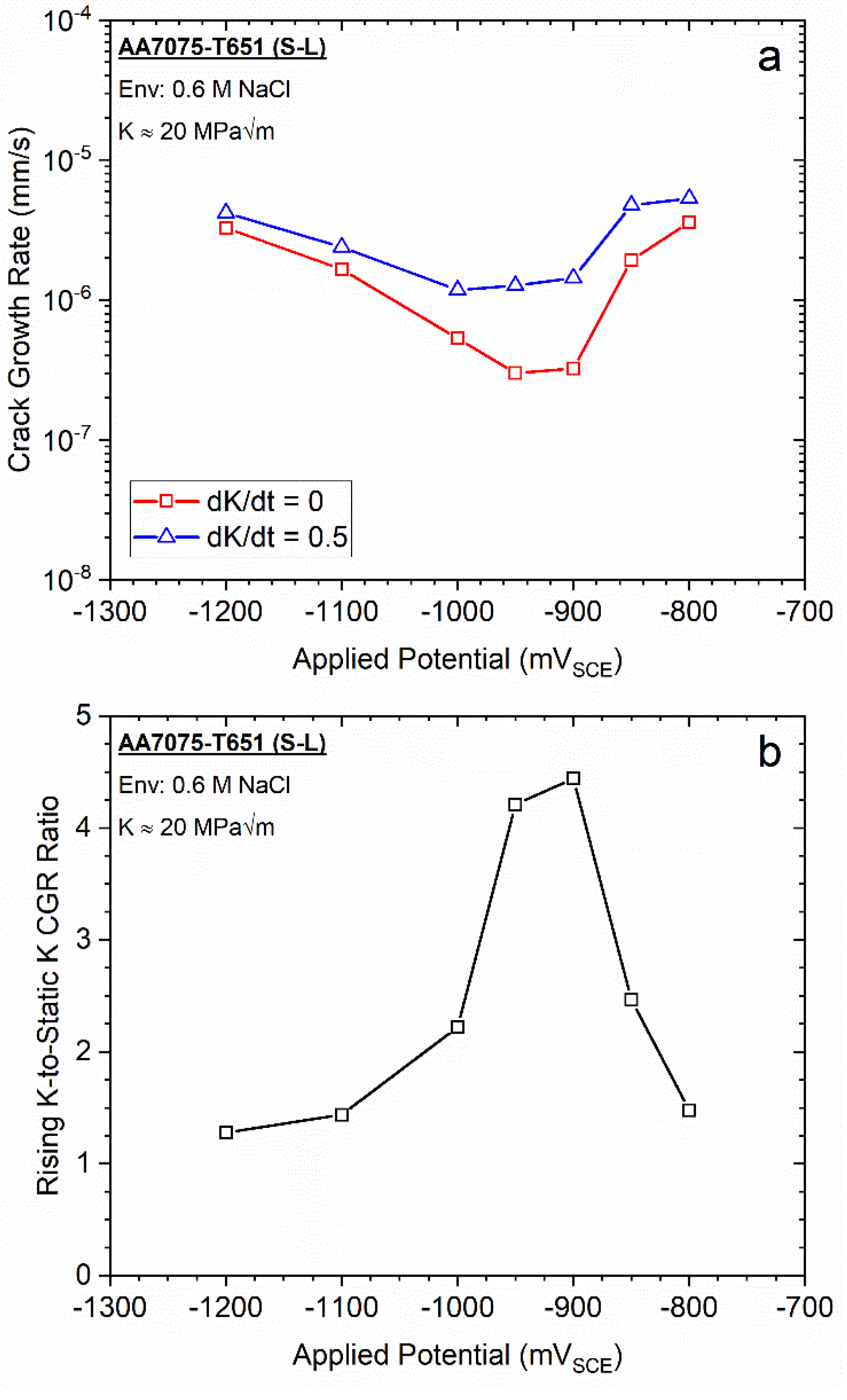
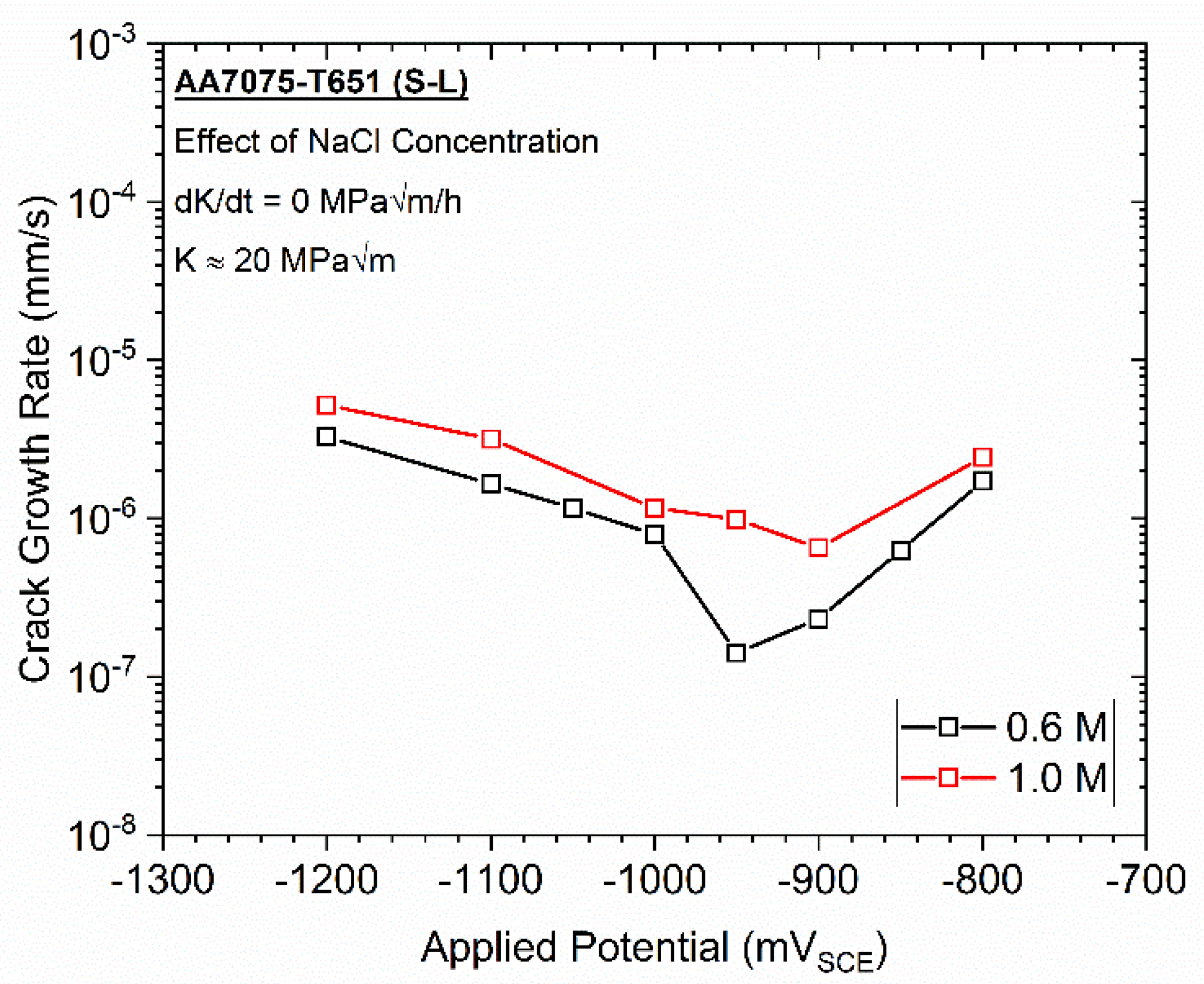
3.1. Comparison of Rising vs. Static K Testing for AA7075-T651 Immersed in 0.6 M NaCl as a Function of Applied Potential

Literature demonstrates that ‘false’, non-crack extension-related dcPD voltage increases will be induced by increasing strain [71,72,73] (as will occur during rising K or displacement experiments), which can obfuscate the comparison of crack growth rates measured with rising K and static K approaches. At the low stress intensities pertinent to EAC, prior work has postulated that this strain-induced ‘false’ crack growth is likely driven by plasticity-induced modifications of the material resistivity within the plastic zone at the crack tip [55,73,74,75]. Strain-induced modifications in sample geometry have also been suggested as a possible contribution [71,76]. Regardless of the source, it is necessary to correct rising K-generated data to remove these ‘false’ dcPD-indicated crack extensions so that the ‘true’ crack extension can be determined. An example of the subtraction-based correction procedure [55] employed in the current study is shown in Figure 1 using the results from the experiment on AA7075-T651 immersed in 0.6 M NaCl at an applied potential of −1200 mVSCE and dK/dt = 0.5 MPa√m/h. It should be noted that this subtraction-based correction can be performed using either the da/dt vs. K or K vs. crack length paradigm due to the fixed dK/dt testing methodology [55]; in the current study, the subtraction is performed using the K vs. crack length paradigm. It is recognized that other methods to account for this ‘false’ crack growth contribution to the dcPD signal have been proposed [77,78]. However, these approaches assume that the ‘false’ crack growth contribution is negligible upon the onset of real crack extension. Such an assumption is not necessarily rigorous for subcritical cracking experiments due to the potential for slow crack growth, as will be shown for the current alloy under certain environmental conditions.
To perform this correction, a companion experiment at dK/dt = 0.5 MPa√m/h was first conducted in dry N2 (a known inert environment, indicated by the red dashed line in Figure 1a), where true crack extension does not occur. These inert environment data represent the magnitude of the ‘false’ crack extension as a function of K (Given that these experiments were performed at a fixed dK/dt, followed by a static K segment after 137,100 s, it is straightforward to interchange K and time for this correction. which can then be converted to time). Since the ‘as-measured’ crack growth at −1200 mVSCE in 0.6 M NaCl (indicated by black line in Figure 1a) represents the sum of the ‘false’ and ‘true’ crack growth contributions, the latter (indicated by the blue line in Figure 1a) can then be isolated by subtracting the dry N2 response from as-measured data. Once the ‘true’ crack growth versus time response is known, it can then be differentiated to obtain the crack growth rate as a function of the applied K. An example using the −1200 mVSCE data from Figure 1a is shown in Figure 1b. As expected from the corrected crack extension versus time trace in Figure 1a, the crack growth rate increases with increasing K during the rising K segment of the experiment once the threshold stress intensity (KTH; 3 MPa√m in Figure 1b) is exceeded. Upon switching to the fixed K segment at K = 20 MPa√m, the crack growth rate slightly decreases from ≈4 × 10⁻⁶ mm/s to a constant value of ≈3 × 10⁻⁶ mm/s, consistent with the generally linear crack length versus time relationship in Figure 1a. These constant K and rising K-generated crack growth rates can then be compared to inform the loading rate sensitivity of EAC for the tested alloy/environment combination.
The crack growth rates measured at K = 20 MPa√m in 0.6 M NaCl at applied potentials ranging from −800 to −1200 mVSCE using the above combined fixed dK/dt (0.5 MPa√m/h) and fixed K testing methodology are shown in Figure 2a. Both the constant and rising K-based crack growth rates exhibit similar dependencies on applied potential. Specifically, relatively elevated crack growth rates are observed at applied potentials near the open circuit potential (OCP; −800 mVSCE), followed by decreased crack growth rates between −900 and −1000 mVSCE, and then an increase in crack growth rates for potentials more negative than −1000 mVSCE. While both approaches exhibit similar crack growth rates versus applied potential dependencies, the rising K-based crack growth rates are consistently increased relative to the static K-based crack growth rates. Interestingly, the difference in crack growth rate between the rising K and static K segments as a function of applied potential is non-constant. As demonstrated in Figure 2b, the ratio of the rising K to static K measured crack growth rates for AA7075-T651 in 0.6 M NaCl at K = 20 MPa√m varies from approximately 1.25 to 4.25 (at −1200 and −950 mVSCE, respectively). In particular, the larger differences generally occur at the applied potentials that encompass the ‘well’ noted in Figure 2a (−900 to −1000 mVSCE), while the two methods exhibit closer agreement at applied potentials outside of the ‘well’ region.

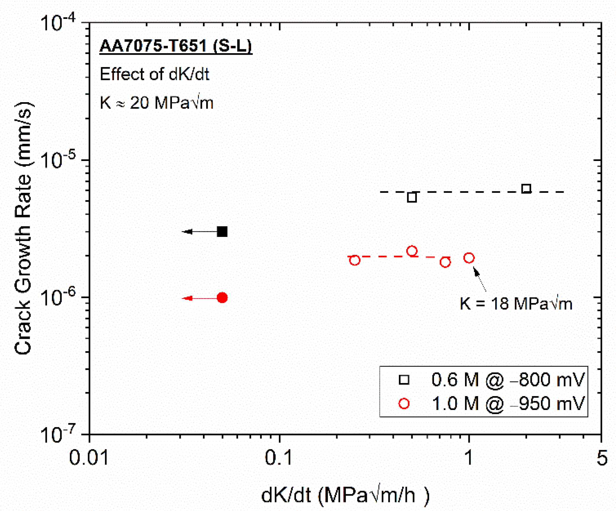
3.2. Effect of dK/dt on EAC for AA7075-T651 at −950 mVSCE in 1.0 M NaCl

The influence of NaCl concentration (0.6 and 1.0 M NaCl) on the crack growth rates under static K (K = 20 MPa√m) as a function of applied potential are shown in Figure 3. These data were generated via a stepped potential-based approach, where the applied potential was systematically increased from −1200 to −800 mVSCE, with each potential step held for at least 25,000 s, while the applied K was held constant at 20 MPa√m. For all evaluated applied potentials, an increased crack growth rate was observed for 1.0 M NaCl relative to 0.6 M NaCl, consistent with expectations of more severe EAC with increased halide concentration in Al alloys [8]. However, the lowest crack growth rates in 1.0 M NaCl are observed between −900 and −1000 mVSCE, confirming the presence of the same ‘well’ noted in 0.6 M NaCl. Based on the results presented in Figure 2, AA7075-T651 exhibits the largest loading rate dependence at the applied potential of −950 mVSCE in 0.6 M NaCl. However, the total crack extension during the rising K segment at this condition was ~30 µm, which severely limits the dK/dt range that can be evaluated (since less crack extension is expected to occur as the dK/dt is increased [55]). As such, given that this potential resides in the well for both concentrations and that it is expected to yield the largest loading rate dependence, the influence of dK/dt will be assessed in 1.0 M NaCl at −950 mVSCE.
The effect of dK/dt on the crack growth rate versus K relationship for AA7075-T651 at an applied potential of −950 mVSCE in 1.0 M NaCl is shown in Figure 4. In general, a minimal dK/dt influence is observed for dK/dt ranging from 0.25 to 1.0 MPa√m/h. For example, KTH was effectively independent of dK/dt over the tested range, ranging from 8 to 10 MPa√m, and the observed differences in crack growth rate for a given K are consistent with expected test-to-test scatter in EAC-based experiments [73,79] (especially for Al-based alloys [80,81,82]). Moreover, the relative ordering of the crack growth rates for a given K does not exhibit a meaningful trend as a function of dK/dt.
Collectively, these data demonstrate that EAC growth rate in AA7075-T651 immersed in 1.0 M NaCl at an applied potential of −950 mVSCE is nominally constant at a given K value for positive dK/dt values. This limited effect of dK/dt is further supported in Figure 5, where the crack growth rates at K = 20 MPa√m for testing in 0.6 M NaCl at −800 mVSCE (black squares) and 1.0 M NaCl at −950 mVSCE (red circles) are compared as a function of dK/dt. Specifically, the measured crack growth rate appears to be nominally independent of dK/dt over the test range from 0.25 to 2.0 MPa√m/h. However, it should be noted that for both conditions, testing at dK/dt > 0 resulted in an increased crack growth rate relative to that measured at dK/dt = 0 (indicated by the closed symbols in Figure 5). This observation has important implications regarding the efficacy of different testing methodologies for assessing EAC, which will be discussed in subsequent sections.

4. Discussion

4.1. Influence of Material/Environment Susceptibility on the Loading Rate Dependence of EAC

The preceding results demonstrate that EAC in AA7075-T651 exhibits a modest dependence on loading rate when comparing dK/dt = 0 and dK/dt > 0, but similar behavior for positive dK/dt ranging from 0.25 to 2.0 MPa√m/h. Specifically, for testing in 0.6 M NaCl at different applied potentials, the ratio of the crack growth rates at dK/dt = 0.5 and 0 MPa√m/h for K = 20 MPa√m varied from 1.25 to 4.25 (Figure 2a). Furthermore, a 2-fold difference is observed between the rising and static K growth rates at K = 20 MPa√m in 1.0 M NaCl at −950 mVSCE (Figure 5). However, the crack growth rate versus K relationships for −950 mVSCE in 1.0 M NaCl (Figure 4) were observed to be nominally dK/dt-independent for dK/dt ranging from 0.25 to 1.0 MPa√m/h. Similar trends were also noted in Figure 5 for the crack growth rate versus dK/dt behavior in 0.6 M NaCl at −800 mVSCE for dK/dt ranging from 0.5 to 2.0 MPa√m/h. These observations motivate discussion of (1) the relevance and magnitude of loading rate dependence in the context of other material systems, (2) the variation in loading rate influence with applied potential (e.g., environmental severity), and (3) the insensitivity of the EAC behavior in AA7075-T651 at positive dK/dt.
The observed dependence (albeit modest) of EAC in AA7075-T651 on loading rate (specifically between dK/dt = 0 and > 0 MPa√m/h) is consistent with prior studies in both Al and other alloy systems. While studies on Al alloys are limited, it is notable that Dietzel et al. observed a similar modest loading rate dependence for EAC in AA2024-T351 immersed in 3.5% NaCl at open circuit potential [51] (−720 mVSCE [83]). Regarding other alloy systems, Gangloff et al. observed a 30-fold increase in crack growth rate under rising K-based loading (dK/dt = 1.1 MPa√m/h) relative to static K loading at K = 53 MPa√m for a Ni-Cu superalloy (Monel K-500) immersed in 0.6 M NaCl at −800 mVSCE [73]. Experiments by Harris et al. on a separate material lot of Monel K-500 in 0.6 M NaCl at −950 mVSCE measured a 25-fold increase in crack growth rate for rising K-based testing when dK/dt was increased from 0.2 to 20 MPa√m/h when compared at K = 75 MPa√m [55]. Strong dK/dt-dependencies have also been observed for non-seawater environments. For example, experiments on Fe and Ni-based alloys immersed in representative nuclear power environments observed increases in crack growth rates of nearly two orders of magnitude when the applied K increased with crack length versus testing where K was held constant as the crack extended [84,85,86].
The impact of applied potential (Figure 2 and Figure 5) on the dK/dt dependence of EAC in AA7075-T651 is also directionally consistent with literature on Monel K-500, where the dK/dt dependence of da/dt was strongly diminished as the environment became more severe (i.e., as the applied potential became increasingly negative) [55,73]. An important role of the environment severity and material EAC susceptibility on the dK/dt-dependence was also noted for Thodla et al. in IN718. Specifically, a strong dK/dt dependence was observed when IN718 immersed in 3.5% NaCl solution at an applied potential of −1050 mVSCE, while a much weaker dK/dt dependence was noted for the same alloy when immersed in 0.5 M H2SO4 solution under galvanostatic conditions (5 mA/cm2) [87]. Lastly, from the perspective of KTH, 4340 steel exposed to low pressure H2 gas was found to have a strongly loading rate-dependent KTH, while a negligible loading rate influence was observed when this alloy was exposed to H2S gas [88].
Taken together, the observation of non-zero crack growth rates under static K conditions (Figure 2 and Figure 3) and the generally modest influence of dK/dt (Figure 4 and Figure 5) across all tested conditions provide an opportunity to comment on the factors governing EAC behavior in AA7075-T651. Since continued crack extension does not require an increasing mechanical driving force, this implies that EAC in AA7075-T651 is a stress-controlled fracture process (i.e., has a flat R curve), where crack growth occurs once a critical driving force is applied that exceeds the intrinsic material resistance [45]. Moreover, literature indicates that EAC in 7xxx-series Al alloys is driven by hydrogen embrittlement [49,89,90,91], though it is likely that the anodic dissolution of grain boundaries (due to element segregation and/or the presence of grain boundary precipitates) [92,93,94,95,96,97] synergistically contributes, as has been observed in 5xxx-series Al [98]. The Ritchie–Knott–Rice (RKR) model [99] can therefore provide a generalized framework to understand the factors governing EAC in AA7075-T651. This framework assumes that crack extension occurs when the tensile opening stress is greater than the material’s fracture stress over a critical distance (xcrit) ahead of the crack tip. In a hydrogen-induced cracking paradigm, the fracture stress required for crack growth is a function of the local hydrogen content [100].
The presence of a constant, subcritical da/dt under static K loading (Figure 2 and Figure 3) suggests that EAC in AA7075-T651 is likely mediated by a time-dependent process (otherwise, rapid fracture should have occurred given that fracture is stress-controlled). From the perspective of the RKR model, the sustained crack growth at dK/dt = 0 (i.e., where there is no change in driving force) indicates that this governing time-dependent process could be associated with attaining the critical hydrogen concentration necessary for fracture at xcrit. Prior literature suggests that the rate of crack advance during EAC under stress-controlled conditions is related to hydrogen diffusion [55,101], which would be consistent with two observations in the current study. First, regarding the minimal dK/dt-dependence of EAC for dK/dt > 0 (Figure 4 and Figure 5), such behavior would be observed if the applied dK/dt are sufficiently slow such that hydrogen can diffuse to xcrit in sufficient quantities to induce crack growth via lowering the intrinsic resistance [55]. However, if the dK/dt is fast enough that hydrogen cannot sufficiently diffuse to xcrit, then a decrease in susceptibility would be observed, as has been noted in other alloy systems [102] and by Dietzel et al. for AA2024-T351. Second, a diffusion-based mechanism would also explain the nominally ‘slow’ da/dt (relative to other alloys [101]) observed for AA7075-T651 across all tested environments in the current study (Figure 2, Figure 3, Figure 4 and Figure 5). If hydrogen diffusion provides the time basis for the da/dt of a given material/environment combination, then the slow diffusivity of hydrogen in Al alloys [103] would imply that reduced crack growth rates should be expected, even under stress-controlled fracture conditions.

4.2. Implications of Results on Current EAC Standardized Testing Approaches

The present study also provides an opportunity to comment on the efficacy of current fracture mechanics-based standards for assessing EAC with regards to the influence of applied loading rate. Briefly, the three primary fracture mechanics-based EAC testing standards all employ different loading rates: ASTM F1624 (dK/dt = 0) [40], ASTM E1681/ASTM G168 (most commonly used in configuration that results in dK/dt < 0) [38,39], and ISO7539-9 (uses a fixed displacement rate to generate dK/dt > 0) [41]. As such, it is critical to understand the influence of applied loading rate on the measured EAC behavior to ensure conservatism (In the context of EAC testing, a conservative approach yields increased susceptibility (e.g., a lower KTH or a faster crack growth rate for a given K) relative to a second approach performed under identical environmental conditions.) of generated susceptibility data and maximize testing efficiency. Regarding the former, the results shown in Figure 2 and Figure 5 demonstrate that dK/dt > 0 testing exhibits similar or conservative crack growth rates relative to dK/dt = 0 methods. Specifically, faster crack growth rates were measured for AA7075-T651 under rising K as compared to static K loading across all tested applied potentials and solution concentrations. This observation of rising K-based methods yielding increased crack growth rates is consistent with recent literature examining loading rate effects on EAC in a Ni-Cu superalloy [55,73]. For example, Harris et al. measured a 44-fold and 2-fold increase in crack growth rate during comparative rising K and static K testing on Monel K-500 immersed in 0.6 M NaCl at applied potential of −950 and −1200 mVSCE, respectively [55]. Similarly, Gangloff et al. demonstrated that crack growth rates for Monel K-500 immersed in 0.6 M NaCl measured using dK/dt > 0 methods were either faster or equivalent to those measured via ASTM F1624 (dK/dt = 0), depending on the applied potential [73]. Such conservatism was also noted for rising K-based testing in prior studies comparing KTH values measured using ASTM E1681 [39] (which under typical fixed displacement conditions is akin to dK/dt < 0) to those measured via dK/dt > 0 experiments based on ISO 7539-9. Specifically, Nibur and coworkers observed that hydrogen-charged pressure vessel steels tested using a dK/dt > 0 approach consistently exhibited a lower KTH compared to experiments performed per ASTM E1681 [56,57]. Similar behavior was reported by Gangloff for hydrogen precharged Cr-Mo steels [43] and by Dietzel for AA2024-T351 immersed in 3.5% seawater [104].
In addition to the observed conservatism of EAC metrics generated using a dK/dt > 0 testing methodology relative to the more widely used approaches codified in ASTM E1681 [39] and ASTM F1624 [40], it is also pertinent to note the significant increase in testing throughput associated with rising K-based methods. This is particularly important for Al-based alloys, who have a suggested test duration of 10,000 h in ASTM E1681 when assessing KTH [39]. As shown in Figure 5, conservative crack growth rates relative to those measured under static K were obtained at dK/dt = 2.0 and 1.0 MPa√m/h for AA7075-T651 exposed to 0.6 M NaCl at −800 mVSCE and 1.0 M NaCl at −950 mVSCE, respectively. Such dK/dt > 0 experiments were completed in 9.5 and 19 h, respectively, clearly demonstrating the substantial improvement in experiment efficiency that can be achieved without compromising the quantitative usefulness of fracture mechanics-based testing. That being said, care must be taken under conditions that result in moderate crack extension in alloys have low fracture toughness (e.g., Al alloys) to avoid utilizing loading rates that are so rapid, they preclude EAC. Such an effect is likely responsible for the seemingly divergent finding of KTH approaching KIC (suggesting reduced susceptibility) and the increase in da/dt (suggesting increasing susceptibility) as the loading rate was increased during testing by Dietzel et al. on AA2024-T351 [51]. Specifically, it is speculated that beyond a critical displacement rate, the rapid loading precluded the time-dependent processes that govern EAC, resulting in fracture occurring at KIC and the measurement of rapid crack growth rates due to ductile tearing.
It is clear from both prior literature data and the results presented herein that current EAC testing standards should be revisited to account for the potentially significant impact of applied loading rate on measured EAC susceptibility. Moreover, it is also necessary to identify the factors that lead to a given alloy/environment combination to exhibit a substantial or negligible loading rate dependence. For example, AA7075-T651 exhibited a generally minimal loading rate-dependence, while a more substantial influence of loading rate has been observed in testing conducting in other alloy systems (such as Monel K-500 [55,73]). The causal factors governing such differences in dependence are not immediately clear and should be the focus of continued study to enable the development of mechanistically informed EAC testing standards.

5. Conclusions

The effect of applied loading rate on the EAC behavior of AA7075-T651 immersed in 0.6 M and 1.0 M NaCl solution at applied potentials between −800 and −1200 mVSCE was assessed using fixed dK/dt and static K testing methodologies. Based on the results of these experiments, the following insights were obtained:
  • AA7075-T651 immersed in both 0.6 M and 1.0 M NaCl exhibited a minimal influence of loading rate on the EAC behavior across all examined applied potentials.
  • The observed minimal influence of loading rate suggests that the fracture behavior of the tested material/environment combination is stress-controlled, consistent with the non-zero crack growth rates measured under static K conditions. The observed stress-controlled EAC behavior was interpreted to be diffusion-limited, which was then utilized to explain the basis for the limited dK/dt-dependence of EAC in AA7075-T651 observed for dK/dt > 0 loading.
  • Across all tested combinations of solution concentration and applied potential, the crack growth rates measured under rising K were greater than those measured under static K conditions. Such results demonstrate the conservativism and efficiency of the rising K methodology relative to current standardized EAC testing approaches, even under conditions that exhibit significant EAC susceptibility. However, caution must be taken to ensure that the employed loading rate does not preclude any required time-dependent process for EAC, as currently suggested in ISO 7539-9 [41].

Author Contributions

Conceptualization, Z.D.H. and J.T.B.; methodology, Z.D.H.; investigation, Z.D.H.; writing—original draft preparation, Z.D.H.; writing—review and editing, Z.D.H. and J.T.B.; supervision, J.T.B.; funding acquisition, J.T.B. All authors have read and agreed to the published version of the manuscript.

Funding

This research was funded by the National Aeronautics and Space Administration (NASA) through the NASA Engineering & Safety Center under Award #80NSSC21P0569 with Heather Hickman as Program Manager.

Institutional Review Board Statement

Not applicable.

Informed Consent Statement

Not applicable.

Data Availability Statement

The data presented in this study are available on request from the corresponding author.

Acknowledgments

The authors thank John Scully and Robert Kelly at the University of Virginia for helpful discussions.

Conflicts of Interest

The authors declare no conflict of interest.

References

  1. Burleigh, T.D. The postulated mechanisms for stress corrosion cracking of aluminum alloys: A review of the literature 1980–1989. Corrosion 1991, 47, 89–98. [Google Scholar] [CrossRef]
  2. Holroyd, N.J.H.; Vasudevan, A.K.; Christodoulou, L. Stress corrosion cracking of high-strength aluminum alloys. In Aluminum Alloys—Contemporary Research and Applications; Vasudevan, A.K., Doherty, R.D., Eds.; Academic Press, Inc.: London, UK, 1989; pp. 463–483. [Google Scholar]
  3. Holroyd, N.J.H. Environment-induced cracking of high-strength aluminum alloys. In Environment-Induced Cracking of Metals; Gangloff, R.P., Ives, M.B., Eds.; NACE International: Houston, TX, USA, 1990; pp. 311–345. [Google Scholar]
  4. Kannan, M.B.; Srinivasan, P.B.; Raja, V.S. Stress corrosion cracking (SCC) of aluminum alloys. In Stress Corrosion Cracking: Theory and Practice; Raja, V.S., Shoji, T., Eds.; Woodhead Publishing Limited: Cambridge, UK, 2011; pp. 307–340. [Google Scholar]
  5. Braun, R. Environmentally assisted cracking of aluminum alloys in chloride solutions. In Proceedings of ICAA-6; Sato, T., Kenkyukai, K., Eds.; Japan Institute of Light Metals: Tokyo, Japan, 1998; pp. 153–164. [Google Scholar]
  6. Ambat, R.; Dwarakadasa, E.S. Effect of hydrogen in aluminium and aluminium alloys: A review. Bull. Mater. Sci. 1996, 19, 103–114. [Google Scholar] [CrossRef]
  7. Holroyd, N.J.H.; Scamans, G.M. Stress corrosion cracking in Al-Zn-Mg-Cu aluminum alloys in saline environments. Met. Mater. Trans. A 2013, 44, 1230–1253. [Google Scholar] [CrossRef] [Green Version]
  8. Speidel, M.O. Stress corrosion cracking of aluminum alloys. Met. Mater. Trans. A 1975, 6, 631–651. [Google Scholar] [CrossRef]
  9. Schwarzenböck, E.; Ollivier, E.; Garner, A.; Cassell, A.; Hack, T.; Barrett, Z.; Engel, C.; Burnett, T.L.; Holroyd, N.H.; Robson, J.D.; et al. Environmental cracking performance of new generation thick plate 7000-T7x series alloys in humid air. Corros. Sci. 2020, 171, 108701. [Google Scholar] [CrossRef]
  10. Brown, R.H.; Sprowls, D.O.; Shumaker, M.B. The resistance of wrought high strength aluminum alloys to stress corrosion cracking. In Stress Corrosion Cracking of Metals—A State of the Art; Craig, H.L., Ed.; ASTM International: West Conshohocken, PA, USA, 1972; pp. 87–118. [Google Scholar]
  11. Hermann, R. Environmentally Assisted fracture of aluminum alloys. Corrosion 1988, 44, 685–690. [Google Scholar] [CrossRef]
  12. Moshtaghi, M.; Safyari, M.; Hojo, T. Effect of solution treatment temperature on grain boundary composition and environmental hydrogen embrittlement of an Al–Zn–Mg–Cu alloy. Vacuum 2021, 184, 109937. [Google Scholar] [CrossRef]
  13. Safyari, M.; Moshtaghi, M.; Kuramoto, S. On the role of traps in the microstructural control of environmental hydrogen embrittlement of a 7xxx series aluminum alloy. J. Alloy. Compd. 2021, 855, 157300. [Google Scholar] [CrossRef]
  14. Moshtaghi, M.; Safyari, M.; Kuramoto, S.; Hojo, T. Unraveling the effect of dislocations and deformation-induced boundaries on environmental hydrogen embrittlement behavior of a cold-rolled Al-Zn-Mg-Cu alloy. Int. J. Hydrog. Energy 2021, 46, 8285–8299. [Google Scholar] [CrossRef]
  15. Oger, L.; Andrieu, E.; Odemer, G.; Peguet, L.; Blanc, C. Hydrogen—Dislocation interactions in a low-copper 7xxx aluminium alloy: About the analysis of interrupted stress corrosion cracking tests. Mater. Sci. Eng. A 2020, 790, 139654. [Google Scholar] [CrossRef]
  16. Holroyd, N.J.H.; Hardie, D. Strain-rate effects in the environmentally-assisted fracture of a commercial high-strength aluminum alloy (7049). Corros. Sci. 1981, 21, 129–144. [Google Scholar] [CrossRef]
  17. Dey, S.; Chattoraj, I. Interaction of strain rate and hydrogen input on the embrittlement of 7075 T6 aluminum alloy. Mater. Sci. Eng. A 2016, 661, 168–178. [Google Scholar] [CrossRef]
  18. Taheri, M.; Albrecht, J.; Bernstein, I.; Thompson, A. Strain-rate effects on hydrogen embrittlement of 7075 aluminum. Scr. Met. 1979, 13, 871–875. [Google Scholar] [CrossRef]
  19. Beavers, J.A.; Koch, G.H. Limitations of the slow strain rate test for stress corrosion cracking testing. Corrosion 1992, 48, 256–264. [Google Scholar] [CrossRef]
  20. Kim, C.D.; Wilde, B.E. A Review of the constant strain-rate stress corrosion cracking test. In Stress Corrosion Cracking—The Slow Strain-Rate Technique; Ugiansky, G.M., Payer, J.H., Eds.; ASTM International: West Conshohocken, PA, USA, 1979; pp. 97–112. ISBN 978-0-8031-0579-9. [Google Scholar]
  21. Henthorne, M. The slow strain rate stress corrosion cracking test—A 50 year retrospective. Corrosion 2016, 72, 1488–1518. [Google Scholar] [CrossRef]
  22. ASTM Standard G129-00, Standard Practice for Slow Strain Rate Testing to Evaluate the Susceptibility of Metallic Materials to Environmentally Assisted Cracking; ASTM International: West Conshohocken, PA, USA, 2000. [CrossRef]
  23. McIntyre, D.R.; Kane, R.D.; Wilhelm, S.M. Slow strain rate testing for materials evaluation in high-pressure H2S environments. Corrosion 1988, 44, 920–926. [Google Scholar] [CrossRef]
  24. Ahluwalia, H. Problems associated with slow strain rate quality assurance testing of nickel-base corrosion resistant alloy tubulars in hydrogen sulfide environments. In Slow Strain Rate Testing for the Evaluation of Environmentally Induced Cracking: Research and Engineering Applications; Kane, R.D., Ed.; ASTM International: West Conshohocken, PA, USA, 1993; pp. 225–339. [Google Scholar] [CrossRef]
  25. Hibner, E.L. Improved SSR Test for Lot Acceptance Criterion. In Slow Strain Rate Testing for the Evaluation of Environmentally Induced Cracking: Research and Engineering Applications; Kane, R.D., Ed.; ASTM International: West Conshohocken, PA, USA, 1993; pp. 290–294. [Google Scholar] [CrossRef]
  26. le Hong, S. Influence of surface condition on primary water stress corrosion cracking initiation of alloy 600. Corrosion 2001, 57, 323–333. [Google Scholar] [CrossRef]
  27. Lee, H.; Kim, Y.; Jeong, Y.; Kim, S. Effects of testing variables on stress corrosion cracking susceptibility of Al 2024-T351. Corros. Sci. 2012, 55, 10–19. [Google Scholar] [CrossRef]
  28. Margot-Marette, H.; Bardou, G.; Charbonnier, J. The application of the slow strain rate test method for the development of linepipe steels resistant to sulphide stress cracking. Corros. Sci. 1987, 27, 1009–1026. [Google Scholar] [CrossRef]
  29. Holroyd, N.; Burnett, T.; Seifi, M.; Lewandowski, J. Improved understanding of environment-induced cracking (EIC) of sensitized 5XXX series aluminium alloys. Mater. Sci. Eng. A 2017, 682, 613–621. [Google Scholar] [CrossRef]
  30. Holroyd, N.H.; Burnett, T.L.; Palmer, B.C.; Lewandowski, J.J. Estimation of environment-induced crack growth rate as a function of stress intensity factors generated during slow strain rate testing of aluminum alloys. Corros. Rev. 2019, 37, 499–506. [Google Scholar] [CrossRef]
  31. Seifi, M.; Ghamarian, I.; Samimi, P.; Collins, P.; Holroyd, N.; Lewandowski, J. Sensitization and remediation effects on environmentally assisted cracking of Al-Mg naval alloys. Corros. Sci. 2018, 138, 219–241. [Google Scholar] [CrossRef]
  32. Haruna, T.; Shibata, T. Initiation and growth of stress corrosion cracks in type 316L stainless steel during slow strain rate testing. Corrosion 1994, 50, 785–791. [Google Scholar] [CrossRef]
  33. Garud, Y.S. An incremental damage formulation for stress corrosion cracking and its application to crack growth interpretation based on CERT data. Corrosion 1990, 46, 968–974. [Google Scholar] [CrossRef]
  34. Máthis, K.; Prchal, D.; Novotný, R.; Hähner, P. Acoustic emission monitoring of slow strain rate tensile tests of 304L stainless steel in supercritical water environment. Corros. Sci. 2011, 53, 59–63. [Google Scholar] [CrossRef]
  35. Sampath, D.; Akid, R.; Morana, R. Estimation of crack initiation stress and local fracture toughness of Ni-alloys 945X (UNS N09946) and 718 (UNS N07718) under hydrogen environment via fracture surface topography analysis. Eng. Fract. Mech. 2018, 191, 324–343. [Google Scholar] [CrossRef]
  36. Martelo, D.; Sampath, D.; Monici, A.; Morana, R.; Akid, R. Correlative analysis of digital imaging, acoustic emission, and fracture surface topography on hydrogen assisted cracking in Ni-alloy 625+. Eng. Fract. Mech. 2019, 221. [Google Scholar] [CrossRef]
  37. Martínez-Pañeda, E.; Harris, Z.D.; Fuentes-Alonso, S.; Scully, J.R.; Burns, J.T. On the suitability of slow strain rate tensile testing for assessing hydrogen embrittlement susceptibility. Corros. Sci. 2020, 163, 108291. [Google Scholar] [CrossRef] [Green Version]
  38. ASTM G168-17: Standard Practice for Making and Using Precracked Double Beam Stress Corrosion Specimens; ASTM International: West Conshohocken, PA, USA, 2017.
  39. ASTM International, Standard Test Method for Determining Threshold Stress Intensity Factor for Environment-Assisted Cracking of Metallic Materials; ASTM International: West Conshohocken, PA, USA, 2003. [CrossRef]
  40. ASTM International, F-1624 Standard Test Method for Measurement of Hydrogen Embrittlement Threshold in Steel by the Incremental Step Loading Technique; ASTM International: West Conshohocken, PA, USA, 2014. [CrossRef]
  41. I.O. for Standardization, ISO 7539-9:2003, Corrosion of Metals and Alloys—Stress Corrosion Cracking; Part 9: Preparation and use of pre-crack specimens for tests under rising load or rising displacement; ISO—International Organization for Standardization: Geneva, Switzerland, 2003.
  42. Gangloff, R.P. Probabilistic fracture mechanics simulation of stress corrosion cracking using accelerated laboratory testing and multi-scale modeling. Corrosion 2016, 72, 862–880. [Google Scholar] [CrossRef]
  43. Gangloff, R.P. Hydrogen assisted cracking of high strength alloys. In Comprehensive Structural Inteqrity; Milne, I., Ritchie, R.O., Karihaloo, B., Eds.; Elsevier Science: New York, NY, USA, 2003; pp. 31–101. [Google Scholar]
  44. Gangloff, R.P.; Harlow, D.G. Interdisciplinary multi-scale research on environment assisted cracking: The 50 year legacy of Robert, P. Wei. Int. J. Fatigue 2017, 104, 81–98. [Google Scholar] [CrossRef]
  45. Anderson, T.L. Fracture Mechanics: Fundamentals and Applications, 3rd ed.; Taylor & Francis: Boca Raton, FL, USA, 2005. [Google Scholar]
  46. Dietzel, W. Rising displacement stress corrosion cracking testing. Met. Mater. Trans. A 2010, 42, 365–372. [Google Scholar] [CrossRef]
  47. Sarkar, B.; Marek, M.; Starke, E.A. The effect of copper content and heat treatment on the stress corrosion characteristics of Ai-6Zn-2Mg-X Cu alloys. Met. Mater. Trans. A 1981, 12, 1939–1943. [Google Scholar] [CrossRef]
  48. Vogt, H.; Speidel, M. Stress corrosion cracking of two aluminum alloys: A comparison between experimental observations and data based on modelling. Corros. Sci. 1998, 40, 251–270. [Google Scholar] [CrossRef]
  49. Holroyd, N.J.H.; Scamans, G.M. Crack propagation during sustained-load cracking of Al-Zn-Mg-Cu aluminum alloys exposed to moist air or distilled water. Met. Mater. Trans. A 2011, 42, 3979–3998. [Google Scholar] [CrossRef]
  50. Young, G.A.; Scully, J.R. The effects of test temperature, temper, and alloyed copper on the hydrogen-controlled crack growth rate of an Al-Zn-Mg-(Cu) alloy. Met. Mater. Trans. A 2002, 33, 1167–1181. [Google Scholar] [CrossRef]
  51. Dietzel, W.; Schwalbe, K.-H.; Wu, D. Application of fracture mechanics techniques to the environmentally assisted cracking of Aluminum 2024. Fatigue Fract. Eng. Mater. Struct. 1989, 12, 495–510. [Google Scholar] [CrossRef]
  52. Pickens, J.R.; Langan, T.J. The effect of solution heat-treatment on grain boundary segregation and stress-corrosion cracking of Al-Zn-Mg alloys. Met. Mater. Trans. A 1987, 18, 1735–1744. [Google Scholar] [CrossRef]
  53. Ferrer, C.P.; Koul, M.G.; Connolly, B.J.; Moran, A.L. Improvements in strength and stress corrosion cracking properties in aluminum alloy 7075 via low-temperature retrogression and re-aging heat treatments. Corrosion 2003, 59, 520–528. [Google Scholar] [CrossRef]
  54. Lee, S.-M.; Pyun, S.-I.; Chun, Y.-G. A critical evaluation of the stress-corrosion cracking mechanism in high-strength aluminum alloys. Met. Mater. Trans. A 1991, 22, 2407–2414. [Google Scholar] [CrossRef]
  55. Harris, Z.D.; Dubas, E.M.; Popernack, A.S.; Somerday, B.P.; Burns, J.T. Elucidating the loading rate dependence of hydrogen environment-assisted cracking in a Ni-Cu superalloy. Theor. Appl. Fract. Mech. 2021, 111, 102846. [Google Scholar] [CrossRef]
  56. Nibur, K.A.; Somerday, B.P.; Marchi, C.S.; Foulk, J.W.; Dadfarnia, M.; Sofronis, P.; Marchi, C.S. The relationship between crack-tip strain and subcritical cracking thresholds for steels in high-pressure hydrogen gas. Met. Mater. Trans. A 2012, 44, 248–269. [Google Scholar] [CrossRef]
  57. Somerday, B.; Nibur, K. Effect of applied K level on the crack-arrest threshold in hydrogen environments: Mechanics-based interpretation. Corrosion 2019, 75, 929–937. [Google Scholar] [CrossRef]
  58. Papazian, J.; Anagnostou, E.L.; Christ, R.J.; Engel, J.; Fridline, D.; Hoitsma, D.; Madsen, J. DARPA/NCG Structural Integrity Prognosis System, HR0011-04; DARPA: Arlington, VA, USA, 2009. [Google Scholar]
  59. B209-14 Standard Specification for Aluminum and Aluminum-Alloy Sheet and Plate; ASTM International: West Conshohocken, PA, USA, 2014. [CrossRef]
  60. Burns, J.T.; Larsen, J.M.; Gangloff, R.P. Driving forces for localized corrosion-to-fatigue crack transition in Al-Zn-Mg-Cu. Fatigue Fract. Eng. Mater. Struct. 2011, 34, 745–773. [Google Scholar] [CrossRef]
  61. Payne, J.; Welsh, G.; Christ, R.J., Jr.; Nardiello, J.; Papazian, J.M. Observations of fatigue crack initiation in 7075-T651. Int. J. Fatigue 2010, 32, 247–255. [Google Scholar] [CrossRef]
  62. ASTM A693-16 Standard Specification for Precipitation-Hardening Stainless and Heat-Resisting Steel Plate, Sheet, and Strip; ASTM International: West Conshohocken, PA, USA, 2016.
  63. Tada, H.; Paris, P.C.; Irwin, G.R. The Stress Analysis of Cracks Handbook; Paris Productions Incorporated: St. Louis, MO, USA, 1985. [Google Scholar]
  64. Dowling, N.E. Fatigue at notches and the local strain and fracture mechanics approaches. In Fracture Mechanics, Proceedings of the Eleventh National Symposium on Fracture Mechanics: Part I; Smith, C., Ed.; ASTM International: West Conshohocken, PA, USA, 1979; pp. 247–273. [Google Scholar]
  65. Smith, R.; Miller, K. Fatigue cracks at notches. Int. J. Mech. Sci. 1977, 19, 11–22. [Google Scholar] [CrossRef]
  66. Gangloff, R.; Slavik, D.; Piascik, R.; Van Stone, R. Direct current electrical potential measurement of the growth of small cracks. In Small-Crack Test Methods; Larsen, J.M., Allison, J.E., Eds.; ASTM International: Philadelphia, PA, USA, 1992; pp. 116–168. [Google Scholar]
  67. Donald, J.K.; Ruschau, J. Direct current potential difference fatigue crack measurement techniques. In Fatigue Crack Measurements: Techniques and Applications; Marsh, K.J., Smith, R.A., Ritchie, R.O., Eds.; EMAS: Warrington, UK, 1991; pp. 11–37. [Google Scholar]
  68. Johnson, H.H. Calibrating the electric potential method for studying slow crack growth. Mater. Res. Stand. 1965, 5, 442–445. [Google Scholar]
  69. ASTM Standard E647-13: Standard Test Method for Measurement of Fatigue Crack Growth Rates; ASTM International: West Conshohocken, PA, USA, 2013. [CrossRef]
  70. Popernack, A. Loading Rate Effects on the Hydrogen Enhanced Cracking Behavior of Ni- and Co-based Superalloys for Marine Applications; University of Virginia: Charlottesville, VA, USA, 2017. [Google Scholar]
  71. Tarnowski, K.; Dean, D.; Nikbin, K.; Davies, C. Predicting the influence of strain on crack length measurements performed using the potential drop method. Eng. Fract. Mech. 2017, 182, 635–657. [Google Scholar] [CrossRef]
  72. Ritchie, R.O.; Bathe, K.J. On the calibration of the electrical potential technique for monitoring crack growth using finite element methods. Int. J. Fract. 1979, 15, 47–55. [Google Scholar] [CrossRef]
  73. Gangloff, R.P.; Ha, H.M.; Burns, J.T.; Scully, J.R. Measurement and modeling of hydrogen environment-assisted cracking in monel K-500. Met. Mater. Trans. A 2014, 45, 3814–3834. [Google Scholar] [CrossRef] [Green Version]
  74. Burns, J.T.; Harris, Z.D.; Dolph, J.D.; Gangloff, R.P. Measurement and modeling of hydrogen environment-assisted cracking in a ni-cu-al-ti superalloy. Met. Mater. Trans. A 2016, 47, 990–997. [Google Scholar] [CrossRef]
  75. Harris, Z.D.; Burns, J.T. The effect of isothermal heat treatment on hydrogen environment-assisted cracking susceptibility in Monel K-500. Mater. Sci. Eng. A 2019, 764, 138249. [Google Scholar] [CrossRef]
  76. Wilkowski, G.M.; Wambaugh, J.O.; Prabhat, K. Single-Specimen J-resistance curve evaluations using the direct-current electric potential method and a computerized data acquisition system. In Fracture Mechanics: Fifteenth Symposium; Sanford, R.J., Ed.; ASTM International: West Conshohocken, PA, USA, 1984; pp. 553–576. [Google Scholar]
  77. ASTM E1457-19e1: Standard Test Method for Measurement of Creep Crack Growth Times in Metals; ASTM International: West Conshohocken, PA, USA, 2019.
  78. ASTM E1820-20: Standard Test Method for Measurement of Fracture Toughness; ASTM International: West Conshohocken, PA, USA, 2020.
  79. Harris, Z.D.; Guiseva, K.; Scully, J.R.; Burns, J.T. On the hydrogen environment-assisted cracking resistance of a compositionally complex Co–Ni–Cr–Fe–Mo–Ti alloy. Mater. Sci. Eng. A 2021, 802, 140601. [Google Scholar] [CrossRef]
  80. Steiner, P.; Harris, Z.; Moraes, C.V.; Kelly, R.; Burns, J. Investigation of IG-SCC growth kinetics in Al-Mg alloys in thin film environments. Corrosion 2021. [Google Scholar] [CrossRef]
  81. Steiner, P.; Burns, J. Mechanistic studies of intergranular stress corrosion cracking in Al-Mg alloys under atmospheric exposure conditions. Corrosion 2018, 74, 1117–1131. [Google Scholar] [CrossRef]
  82. Crane, C.; Gangloff, R. Stress corrosion cracking of Al-Mg alloy 5083 sensitized at low temperature. Corrosion 2015, 72, 221–241. [Google Scholar] [CrossRef]
  83. Santucci, R.; Kannan, B.; Scully, J. Electrochemical diagnostic cycle testing of magnesium and magnesium oxide-pigmented primers on AA2024-T351. Corrosion 2018, 74, 96–111. [Google Scholar] [CrossRef]
  84. Chen, K.; Wang, J.; Du, D.; Andresen, P.L.; Zhang, L. dK/da effects on the SCC growth rates of nickel base alloys in high-temperature water. J. Nucl. Mater. 2018, 503, 13–21. [Google Scholar] [CrossRef]
  85. Andresen, P.L.; Morra, M.M. Effect of rising and falling K profiles on SCC growth rates in high-temperature water. J. Press. Vessel. Technol. 2007, 129, 488–506. [Google Scholar] [CrossRef]
  86. Andresen, P.L. Emerging issues and fundamental processes in environmental cracking in hot water. Corrosion 2008, 64, 439–464. [Google Scholar] [CrossRef]
  87. Thodla, R.; Rollins, B.C.; Scott, H.M.; Holtam, C. Effect of strain rate on the fatigue and static crack growth rate of UNS N07718 under cathodic polarization. Corrosion 2017, 9669, 1–10. [Google Scholar]
  88. Clark, W.G., Jr.; Landes, J.D. An evaluation of rising load KISCC testing. In Stress Corrosion—New Approaches; Craig, H.L., Ed.; ASTM International: West Conshohocken, PA, USA, 1976; pp. 108–127. [Google Scholar]
  89. Gruhl, W. Stress corrosion cracking of high strength aluminum alloys. Z. Fur Met. 1984, 75, 819–826. [Google Scholar]
  90. Gest, R.J.; Troiano, A.R. Stress corrosion and hydrogen embrittlement in an aluminum alloy. Corrosion 1974, 30, 274–279. [Google Scholar] [CrossRef]
  91. Polyanskii, V.M. Role of hydrogen embrittlement in the corrosion cracking of aluminum alloys. Mater. Sci. 1986, 21, 301–309. [Google Scholar] [CrossRef]
  92. Chen, J.; Zhang, X.; Zou, L.; Yu, Y.; Li, Q. Effect of precipitate state on the stress corrosion behavior of 7050 aluminum alloy. Mater. Charact. 2016, 114, 1–8. [Google Scholar] [CrossRef]
  93. Knight, S.; Pohl, K.; Holroyd, N.; Birbilis, N.; Rometsch, P.; Muddle, B.; Goswami, R.; Lynch, S. Some effects of alloy composition on stress corrosion cracking in Al-Zn-Mg-Cu alloys. Corros. Sci. 2015, 98, 50–62. [Google Scholar] [CrossRef]
  94. Xu, D.; Birbilis, N.; Rometsch, P. Effect of S-phase dissolution on the corrosion and stress corrosion cracking of an as-rolled Al-Zn-Mg-Cu Alloy. Corrosion 2012, 68, 035001-1. [Google Scholar] [CrossRef]
  95. Hardwick, D.; Thompson, A.; Bernstein, I. The effect of copper content and heat treatment on the hydrogen embrittlement of 7050-type alloys. Corros. Sci. 1988, 28, 1127–1137. [Google Scholar] [CrossRef]
  96. Knight, S.; Birbilis, N.; Muddle, B.; Trueman, A.; Lynch, S. Correlations between intergranular stress corrosion cracking, grain-boundary microchemistry, and grain-boundary electrochemistry for Al-Zn-Mg-Cu alloys. Corros. Sci. 2010, 52, 4073–4080. [Google Scholar] [CrossRef]
  97. Goswami, R.; Lynch, S.; Holroyd, N.J.H.; Knight, S.P.; Holtz, R.L. Evolution of grain boundary precipitates in Al 7075 upon aging and correlation with stress corrosion cracking behavior. Met. Mater. Trans. A 2013, 44, 1268–1278. [Google Scholar] [CrossRef]
  98. Crane, C.; Kelly, R.; Gangloff, R. Crack chemistry control of intergranular SCC in sensitized Al-Mg. Corrosion 2015, 72, 242–263. [Google Scholar] [CrossRef]
  99. Ritchie, R.O.; Knott, J.F.; Rice, J.R. On the relationship between critical tensile stress and fracture toughness in mild steel. J. Mech. Phys. Solids 1973, 21, 395–410. [Google Scholar] [CrossRef]
  100. Akhurst, K.N.; Baker, T.J. The threshold stress intensity for hydrogen-induced crack growth. Met. Mater. Trans. A 1981, 12, 1059–1070. [Google Scholar] [CrossRef]
  101. Gangloff, R.P. Diffusion control of hydrogen environment embrittlement in high strength alloys. Hydrogen Effects on Materials; Moody, N.R., Thompson, A.W., Eds.; The Minerals, Metals & Materials Society: Warrendale, PA, USA, 2002. [Google Scholar]
  102. Raykar, N.; Maiti, S.; Raman, R.S. Modelling of mode-I stable crack growth under hydrogen assisted stress corrosion cracking. Eng. Fract. Mech. 2011, 78, 3153–3165. [Google Scholar] [CrossRef]
  103. Scully, J.; Young, G.; Smith, S. Hydrogen embrittlement of aluminum and aluminum-based alloys. In Gaseous Hydrogen Embrittlement of Materials in Energy Technologies; Gangloff, R.P., Somerday, B.P., Eds.; Woodhead Publishing Limited: Cambridge, UK, 2012; pp. 707–768. [Google Scholar] [CrossRef]
  104. Dietzel, W.; Schwalbe, K.-H. Application of the rising displacement test to SCC investigations. In Slow Strain Rate Testing for the Evaluation of Environmentally Induced Cracking: Research and Engineering Applications; Kane, R.D., Ed.; ASTM International: West Conshohocken, PA, USA, 2009; pp. 134–148. [Google Scholar]
Figure 1. (a) Example of the correction procedure utilized to remove the ‘false’ crack extension due to localized plasticity, which is quantified by the apparent crack extension measured in a dry N2 environment (indicated by red dashed lines). These data can then be differentiated to determine the crack growth rate versus stress intensity relationship, with an example shown in (b).
Cmd 02 00019 g001
Figure 2. (a) Measured crack growth rate versus applied potential relationships for AA7075-T651 immersed in 0.6 M NaCl at K = 20 MPa√m under static K and fixed dK/dt (0.5 MPa√m/h) loading conditions. The ratio of the measured crack growth rates for the two testing approaches as a function of applied potential are shown in (b).
Cmd 02 00019 g002
Figure 3. Measured crack growth rate as a function of applied potential for AA7075-T651 in 0.6 M NaCl (black squares) and 1.0 M NaCl (red squares) at a fixed K = 20 MPa√m.
Cmd 02 00019 g003
Figure 4. Effect of dK/dt on the crack growth rate versus stress intensity relationships for AA7075-T651 in 1.0 M NaCl at an applied potential of −950 mVSCE.
Cmd 02 00019 g004
Figure 5. Effect of dK/dt on measured crack growth rate for AA7075-T651 immersed in 0.6 M NaCl at an applied potential of −800 mVSCE (black squares) and 1.0 M NaCl at an applied potential of −950 mVSCE (red circles at K = 20 MPa√m). The closed symbols correspond to growth rates measured under static K conditions.
Cmd 02 00019 g005
Table 1. Composition of tested AA7075-T651 material heat (in wt. %).
AlZnMgCuCrFeSiMnTi
Bal5.72.51.70.190.260.060.030.03
Table 2. Mechanical properties of tested AA7075-T651 material heat along S-direction.
σYS (MPa)σUTS (MPa)E (GPa)RA
48256170.70.086
Publisher’s Note: MDPI stays neutral with regard to jurisdictional claims in published maps and institutional affiliations.

