Article

An IoT-Based Participatory Antitheft System for Public Safety Enhancement in Smart Cities

1
IT Solutions Applications and R&D Division, Space Hellas, 312 Messogion Ave., GR-15341 Athens, Greece
2
Intralot S.A., 64 Kifissias Ave & 3 Ch. Sambag—S. Chouri Str., GR-15125 Athens, Greece
3
Department of Electrical and Electronic Engineering, Faculty of Engineering, University of West Attica, Thivon Av. 250, GR-12241 Athens, Greece
*
Author to whom correspondence should be addressed.
Submission received: 31 March 2021 / Revised: 21 May 2021 / Accepted: 21 May 2021 / Published: 11 June 2021
(This article belongs to the Special Issue Feature Papers for Smart Cities)

Abstract

:
The risk of theft of goods is certainly an important source of negative influence in human psychology. This article focuses on the development of a scheme that, despite its low cost, acts as a smart antitheft system that achieves small property detection. Specifically, an Internet of Things (IoT)-based participatory platform was developed in order to allow asset-tracking tasks to be crowd-sourced to a community. Stolen objects are traced by using a prototype Bluetooth Low Energy (BLE)-based system, which sends signals, thus becoming a beacon. Once such an item (e.g., a bicycle) is stolen, the owner informs the authorities, which, in turn, broadcast an alert signal to activate the BLE sensor. To trace the asset with the antitheft tag, participants use their GPS-enabled smart phones to scan BLE tags through a specific smartphone client application and report the location of the asset to an operation center so that owners can locate their assets. A stolen item tracking simulator was created to support and optimize the aforementioned tracking process and to produce the best possible outcome, evaluating the impact of different parameters and strategies regarding the selection of how many and which users to activate when searching for a stolen item within a given area.

1. Introduction

Whenever a consumer buys a product, the joy created thanks to this new possession is in danger by the risk of loss or theft of the specific item [1]. Every year millions of motor vehicles are stolen worldwide, causing an enormous loss of capital. For instance, according to the Insurance Information Institute, only in the U.S.A., in 2019, about $6.4 billion was lost to motor vehicle theft [2]. Additionally, according to the International Crime Victim Survey (ICVS) statistics, bicycle theft is four times more likely than automobile theft [3]. Likewise, 70 million smartphones are lost or stolen every year worldwide [4]. In China, 67.2 percent of respondents who participated in a national study, reported themselves as being victims of a bicycle theft within 2002–2007 [5]. This figure is more than double the rate (30 percent) reported from the International Crime Victim Survey in Beijing up to 1997. Generally, vehicle population increases rapidly, while, at the same time, an exponential increase in vehicle theft takes place.
This article presents a smart IoT-based system, called City.Risks, which was developed in order to use the active participation of people to share information data in order to proactively protect citizens from being victims of thefts of their mobile assets, as well as to reactively provide a more timely and effective response and assistance whenever a theft is indicated. This system utilizes a BLE/Wi-Fi gateway, which can be placed in public locations to enhance and facilitate the processes of detection and alerting of stolen moving assets that exist within the areas that are under investigation.
The rest of this article is structured as follows: Section 2 refers to related work. Section 3 describes both the structure and the operation of the system developed. The results achieved by the systems are both presented and evaluated in Section 4. Future research is proposed in Section 5. Finally, in Section 6, concluding remarks are drawn.

2. Related Work

In recent decades, urban populations have continuously increased by a rate that is greater than half a billion inhabitants per decennial on a worldwide basis [6]. This continuously growing urbanism has boosted the growth of various problems, which deteriorate the quality of living in civilian settlements.
The concept of a smart city was introduced in the early 2000s [7]. It refers to urban municipalities that support the integrated use of not only methods and means but also policies and practices to manage resources, assets, and services and to improve the quality of life of their citizens in terms of prosperity, productivity, safety, and sustainability [8,9,10].
The collection of data is an absolutely necessary procedure in the context of smart cities in order to gather information regarding various parameters that are related to all aspects of human activity. Additionally, the data collected have to be processed and transmitted over various distances. Modern technological advances have enabled the inexpensive massive fabrication of wireless sensor nodes that, despite their fairly small dimensions, have remarkable sensing, processing, and communication capabilities. This is the reason why wireless sensor networks (WSNs) and IoT, which have a continuously growing range of applications [11,12,13], are generally considered to be technologies that, when combined with the application of appropriate algorithms, are ideally suited to be deployed in the framework of smart cities [14,15,16].
Regarding public safety, the advancement of technology has enabled the deployment of various surveillance systems for mobile assets since they are the most frequent object of theft.
Specifically, the system proposed in [17] uses a camera to take images of anyone trying to access a vehicle and compares them with images stored of the legal owner of this vehicle, in order to either allow or deny access to the vehicle. Other antitheft systems that have been proposed for motor vehicles or other mobile assets use locating units installed in vehicles (e.g., GPS (Global Positioning System)) for positioning purposes, microprocessors for data processing, GSM (Global System for Mobile Communications) or GPRS (Global Positioning Radio Satellite) units for data transmission, and batteries for power supply [18,19,20,21,22].The question is whether the battery of such systems can be overcome, and, of course, it is directly dependent on the mobile provider. Another approach of antitheft technology, presented in [23], is more complex because it uses face recognition. In [24], a decentralized vehicle antitheft system using blockchain technology and smart contracts was proposed, aiming to improve the antitheft system’s safety and data security by using a proper key that reduces the possibility of leakage of personal information.
Other research teams have introduced schemes using free data transmission networks equipped with BLE devices. Bluetooth Low Energy 4.0 was introduced by the Special Interest Group (SIG) in 2010 [25]. BLE appliances can be powered by using coin-type batteries for a few years via different modes of power consumption [26]. Other studies have confirmed that BLE consumes low amounts of energy with a satisfactory effective range (50 m) [27,28].
Moreover, BLE supports flexible communication protocols, including the low-cost standard, and this makes this technology more competitive than other wireless technologies [26]. Another study presented the performance of experimental tests conducted regarding a BLE device mounted on a motorcycle on the road [29]. The results of these tests showed that the motorcycle antitheft system (MATS) was 100% accurate in all parts of the road at speeds of up to 70 km/h and 94.4% and 90% effective for speeds up to 80 km/h and 90 km/h, respectively.

3. Methods and Materials

The City.Risks project [30] developed a prototype sensor based on Bluetooth Low Energy [31,32]. This sensor node is to be used as a part of an overall participatory sensing system built by the so-called City.Risks network of citizens for stolen objects within urban areas tracing.
Specifically, each mobile asset to be protected is equipped with a customized BLE sensor tag that actively sends signals, thus becoming a beacon. Once such an item (bicycle, motorbike, mobile asset) is lost, the owner can inform the authorities, which in turn broadcast an alert signal to activate the BLE sensor incorporated. To trace the asset with the antitheft tag, participants use the GPS function of their smart phones to scan BLE tags through a specific smartphone client application and report to the City.Risks Operation Center (OC) the location of the asset so that owners can locate their assets, as illustrated in Figure 1.
In order to support and optimize the aforementioned tracking process and produce the best possible outcome, a Stolen Item Tracking Simulator was devised. It aims in evaluating the impact of different parameters and strategies regarding the selection of how many and which users to activate, when searching for a stolen item within a given area.
The utilization of beacons offers a reliable, cost effective solution for accomplishing these activities. The BLE tags enjoy a long-lasting battery life and thanks to their small size can be easily placed on or within the assets. For instance, in the case of bicycles, the advanced Bluetooth beacon sensor includes a function that allows commuters and cyclists to locate their bicycles in real-time through a smartphone application or a cloud-based web application. The application leverages information from Bluetooth beacons, which detect the presence of bicycles. City.Risks is based on Machine to Machine (M2M) structure development [33,34]. The proposed concept is based on four entities, which namely are:
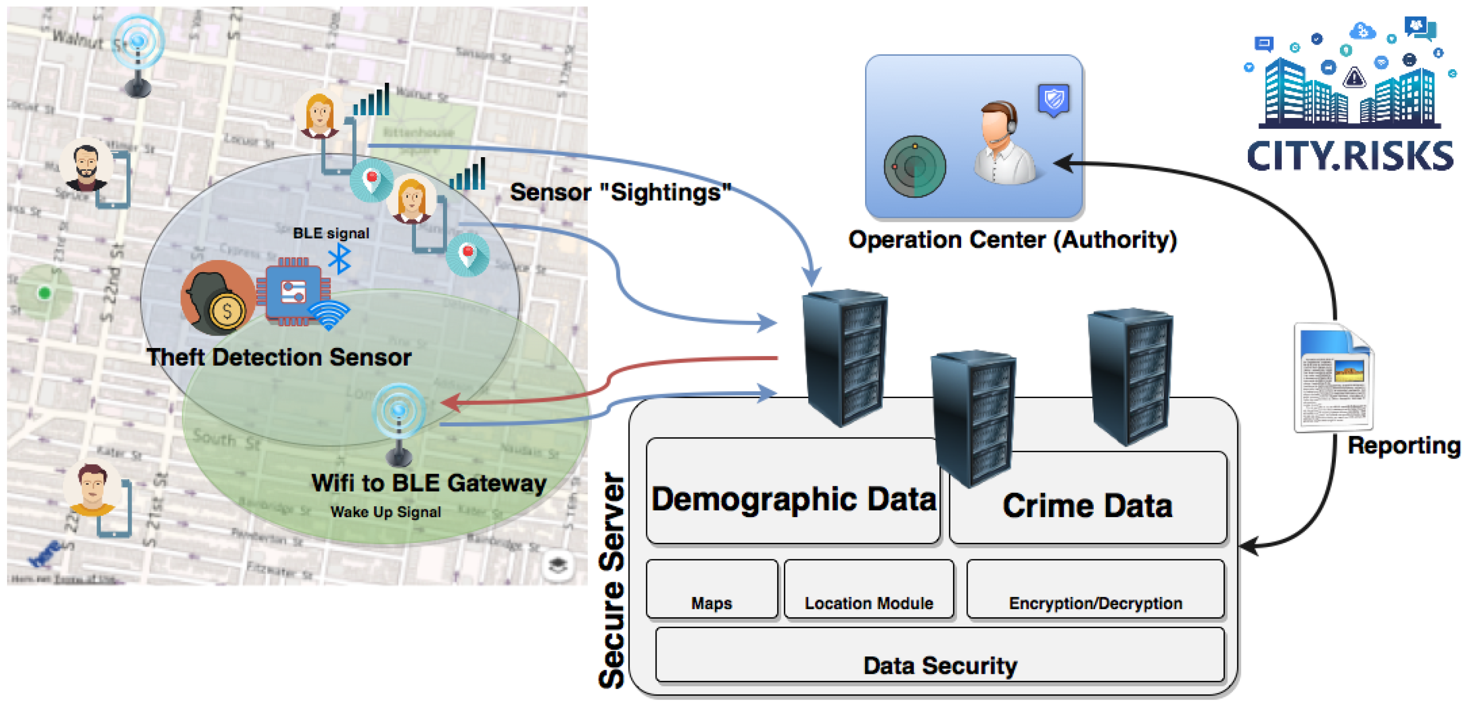
  • City.Risks operation center.
  • BLE/Wi-Fi Gateway bridge.
  • BLE sensors as antitheft devices.
  • Smartphone application.

3.1. Object Tracking Service

The general workflow [35] determined for the object tracking service is as follows:
  • The sensor (with a unique ID) is attached to the object to be tracked.
  • The owner registers the sensor to his/her mobile application.
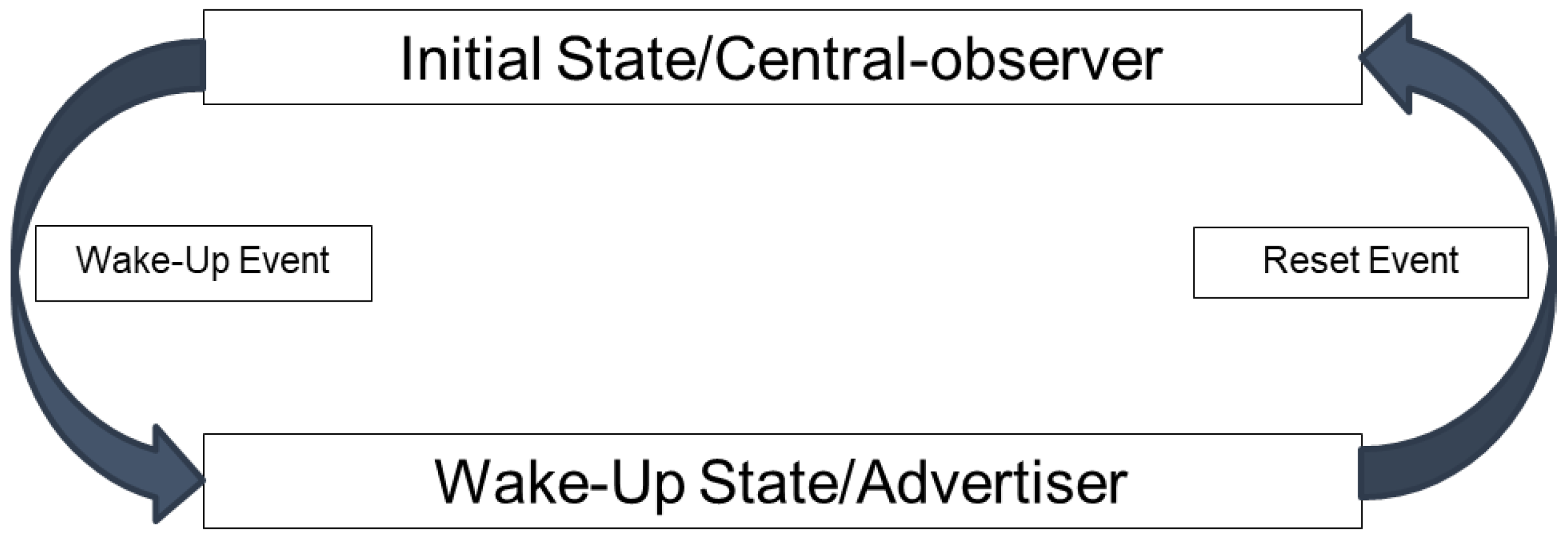
  • The sensor supports two operational modes: an active beacon mode and a receiving mode. It switches between them depending on the owner’s decision.
  • If the object is lost, the owner informs the authorities via a mobile application developed.
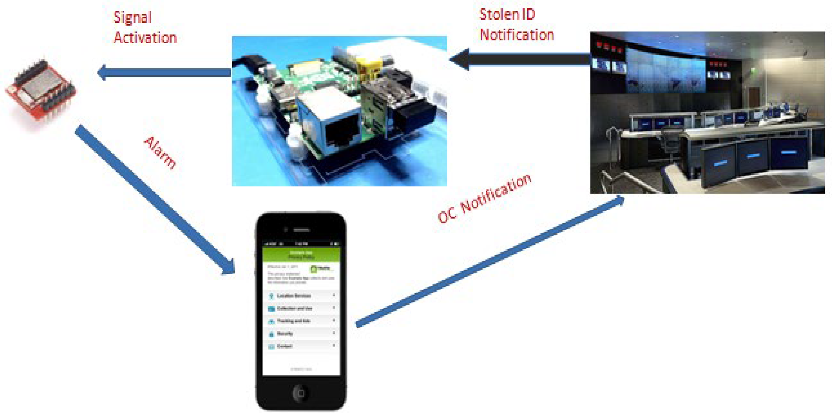
  • The authorities dispatch a request to the intermediate entities (gateways or mobile apps of the community network, depending on the scenario).
  • The intermediate entities send a signal to activate the sensor.
  • The sensor starts broadcasting a beacon.
  • The sensor is detected by a nearby community member smartphone through the participatory sensing approach and the location is reported to the authorities.

3.2. System Architecture

The developed system adopts the system architecture proposed in [36,37], with a similar structure of M2M systems. Figure 2 illustrates the proposed system architecture, which mainly involves two data transmission mechanisms, via: (i) a BLE/Wi-Fi gateway, and (ii) a smartphone to forward to the BLE device.
The BLE/Wi-Fi gateway device is used to optimize the efficiency of the application, fulfilling the objectives of the specific project to cover areas—places where people tend to gather or pass through—in order to enhance participatory sensing, while at the same time facilitating BLE remote tag sensor activation.
Gateway’s core platform is Raspberry Pi3 hardware module incorporating internal Wi-Fi and BLE external USB component as illustrated in Figure 3.
The Wi-Fi module is initially configured and automatically enabled upon power up. The BLE module is connected to the USB external interface of the Raspberry Pi3 platform and can be controlled through the relevant command protocol implemented by the manufacturer. The Gateway is served as an intermediate infrastructure component which can enrich and strengthen the participatory sensing concept of the project. Through its BLE component, it is able to transmit the activation signal to the remote tag, thus enabling the tag’s beacon mode, which in turn operates in stolen mode, broadcasting its alerting signal.
In order to secure safe communication ([38,39]), the following tasks were accomplished:
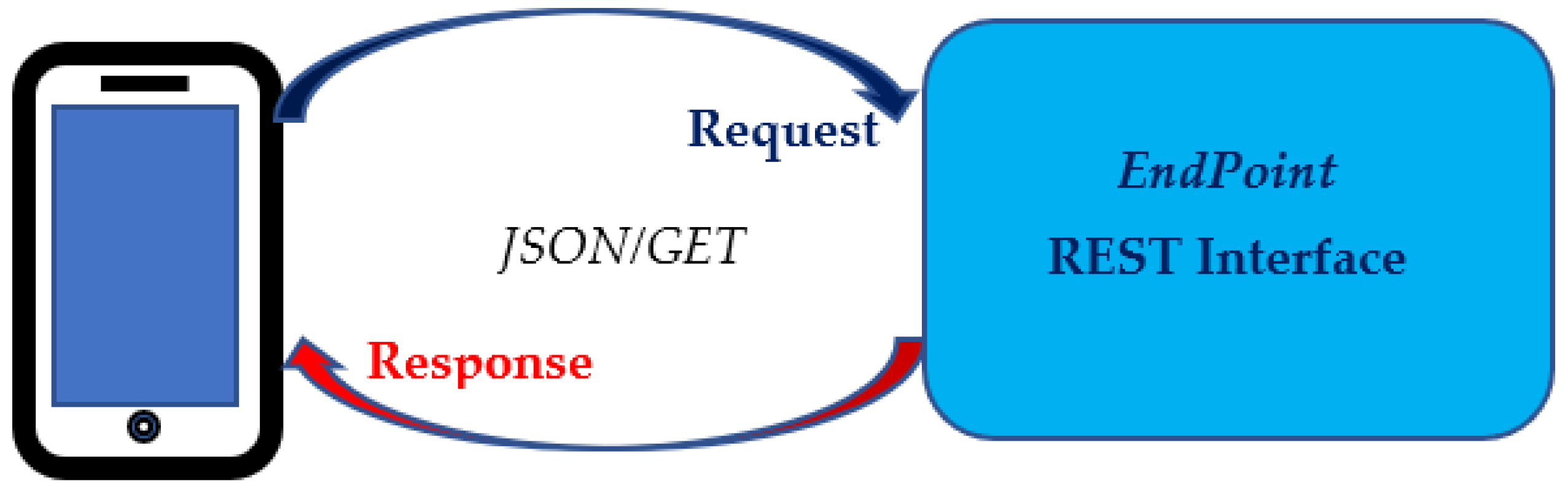
  • The communication between the mobile application/gateways and the Operation Center is via HTTP and is secured with hash authentication. Only City.Risks application users/gateways can communicate with this endpoint and receive information from it.
  • There are only two procedures that can be initiated by the Operation Center, which are activation and discovery. These two procedures can only be initiated after a request from the owner of the device (the one that has registered the device). The request is accompanied by the unique ID of the stolen device and does not contain any personal information about its possessor. Therefore, the tracking procedure focuses on the object and not the owner.
  • No mobile application/gateway can initiate a tracking procedure without a corresponding command of the Operation Center (secured with hash authentication).
  • No user can report a stolen device that he/she does not own (confirmed with local registration). Therefore, a tracking procedure cannot be initiated by other than the owner.
  • The reports received from participatory users during the tracking procedure are not associated with them but with the stolen device. Therefore, the location that accompanies the sighting reports is associated with the ID of the stolen device.

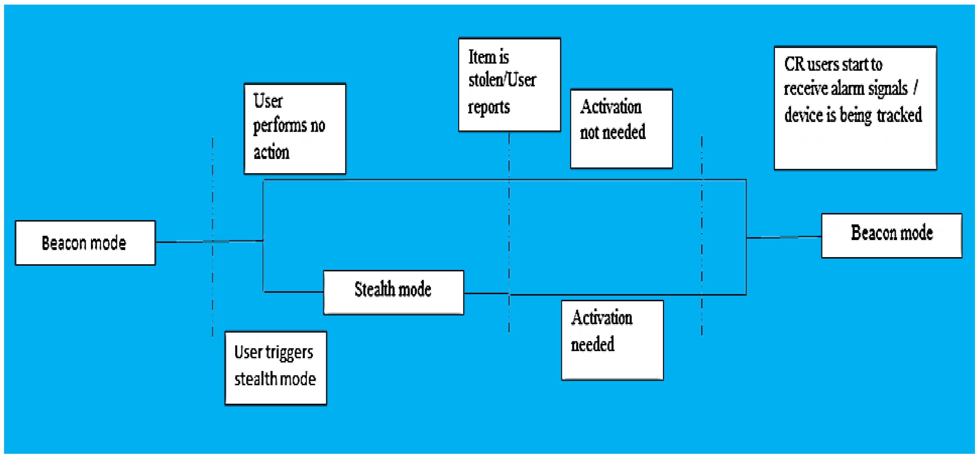
3.3. Sensor Operational Modes and Events Sequence

RedBearLab BLE nanomodule [40] was selected as the BLE prototype platform for the tag sensor. It can operate under a voltage ranging from 1.8 V to 3.3 V, making it able to operate by using a wide variety of battery sources. The BLE device is able to operate in two different modes based on the protocol, i.e., observer (sleep) mode and advertiser (beacon) mode.
The BLE module runs the appropriate firmware application. Certain developed boards are available, offering integrated environments for developing appropriate firmware applications [41,42,43]. BLE should start in central-scanner mode. Whenever a certain advertisement packet is scanned, the device switches to peripheral-advertiser mode. The device can return to the initial state by a reset signal from the owner’s mobile. BLE tag device modes are graphically presented in Figure 4.
  • Stealth mode: In this state the device does not transmit at all. Only the authorized user will be able to connect to the tag by using a passphrase. The passphrase is provided to the Authority by the user that reports the theft. The Authority in turn provides the selected app-users and beacons with it, so they can wake up the device. The purpose of this is to prevent non-authorized personnel from accessing the device.
  • Beacon mode: In this mode, the device is awake and notifies every mobile app user or gateway of its existence. In this mode, the sensor operates under the optimum current consumption scheme.
Beacon mode is selected as the default operation mode. When operating in this mode, battery consumption is kept at a minimum.
When the user leaves his/her personal items in a place that is considered to be unsafe he/she can optionally set the device in “stealth mode”. This is a mode that can receive wake-up signals although it cannot be scanned by other devices. If the specific item is stolen, whilst it is in that mode, a wake-up signal is needed in order to set the device in beacon mode again. Either way to track down the device, the beacon mode is necessitated. A flow chart of the working scheme is illustrated in Figure 5.
The mobile app interacts with the BLE tag all the time but differs according to the BLE tag’s current status:
  • State 1: Tag is in beacon mode—No theft report → no interaction from the mobile app.
  • State 2: Tag is in stealth mode—No theft report → no interaction from the mobile app, except if user wants to switch it back to beacon mode.
  • State 3: Tag is in beacon mode—Theft report → Authorities send signal to the mobile app to search for the beacon signals (track the tag).
  • State 4: Tag is in stealth mode—Theft report → Authorities send signal to the mobile app to activate the tag (switch to beacon mode) → Activation Confirmed → Authorities signal the tracking procedure.
The BLE tag is equipped with a small sized battery to enable a long duration of autonomous operation. The entire assembly is solid and compact within an appropriate small case to allow for ease and secure installation on bicycles, luggage, etc. Specifically, this case is able to:
  • Contain Antitheft Sensor with the coin cell battery case attached;
  • Protect the sensor and the battery from environment factors that could harm the device;
  • Make the device compact and easy to install on multiple items of interest (bicycles, bags, etc.);
  • Allow the developer to make changes to the software without removing the sensor from the case.

3.4. Mobile Phone Application Features

In many cases, a smartphone is used to inform its owner for an event detected by an IoT device [44]. In our study, the mobile phone application includes specific functionalities relevant to theft detection scenario. These functions were mapped to distinct buttons on the mobile app user interface (UI) encompassing certain operational features. The following options are available:
  • Tag register;
  • Tag deregister;
  • Theft report;
  • Stealth mode on;
  • Activate my device.
Tag Register option is used in order to have the tag registered. Various registration methods can be used. For instance, the QR (Quick Response) code is read and next is decoded it into JWT (Jason Web Tokens) format. Then, the user places the battery to power up the sensor tag which normally switches to advertisement mode.
The user, via a password established connection, can put the device into deactivated or stealth mode. Afterwards, the user may initialize the rediscover process tag for at least three seconds. If the tag cannot be detected, it means that it has been switched to receive mode; therefore, it consequently broadcasts no signal at all. Then, the user can reactivate the tag (using the Activate my Device button) and try to discover it. This time the tag should be active and visible. The process is considered to be completed, and the user can proceed to finalizing the tag registration and association with user identity via the City.Risks platform.
To deregister the tag, the user should activate the tag and scan for it to ensure that the tag cannot be deregistered again by another user. Afterwards, the user can deregister the tag via the City.Risks platform and, if required, re-register the unit again.
Theft Report button should be used by the end user in order to report a theft incident to the City.Risks Operation center. In order to facilitate the retrieval process the user -should also report the location of the item’s last known position and the time data. Therefore, location and time related stamp tokens will also be transmitted to the City.Risks authorities.
The REST endpoint in the Operation Center will notify the mobile application that there are stolen devices in the area. The notification method is based on the JSON/GET method [45].
Next, the mobile app requests the required items from the REST endpoint. Again, only stolen BLE tags are received by the app and are stored locally in the app’s database. Figure 6 illustrates the aforementioned approach.
The mobile app then starts advertising processes to activate inactive BLEs listed in the database file. Additionally, it starts the scanning process to pinpoint active BLEs listed in the database file. Once a BLE tag is received, the mobile app sends the scanned device to the relevant web service structure data using the POST method [45].

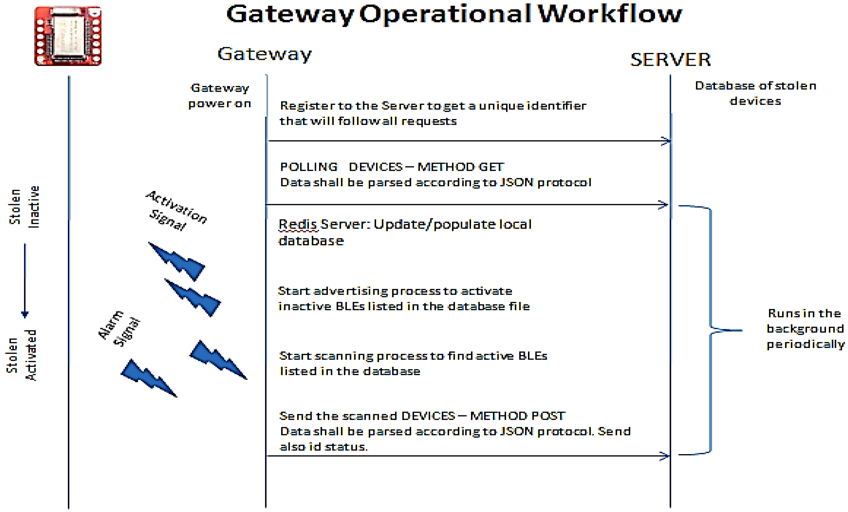
3.5. Gateway Operational Workflow

The operation of the Gateway function is implemented as follows:
In line with the workflow presented in previous sections, the Gateway requests from the server side the BLE tags that have been reported as being stolen. Then, it updates its local database and accordingly configures the BLE/USB module to either broadcast the appropriate device name to the remote BLE tag or alternatively scan, in order to detect already activated tags. In other words, it actually converts its operational status to peripheral mode and starts broadcasting a signal in order to switch the remote BLE sensor from scanner to peripheral mode. When in scanning mode, the BLE tag sensors that are found are reported back to the server as scanned or traced.
On the server side, a storage file structure of BLE tags must be implemented and accessed by the Gateway.
A simplified approach of the BLE tag status on the server side is as follows. It actually represents a database table with the following arguments:
<SensorName>, <SensorStatus>
where:
<SensorName>: Name assigned to the remote BLE sensor upon configuration. This name is used to enable advertising and beacon mode activation. Normally, it can be defined as a multiple character string.
<SensorStatus>: Current status of the BLE remote tag. Normally, it can be defined with three statuses: REG, ACT, and INA.
  • REG: Registered device. The device is considered as being in normal status as there has been no user report concerning their status modification.
  • ACT: Active device. The device is considered as being a stolen device; therefore, associated sensors must be beacon-enabled by the Gateway.
  • INA: Inactive device. The device is considered as being activated (not necessarily found or traced), and beacon broadcast will be terminated by the platform.
Typical gateway operational workflow is illustrated in Figure 7.

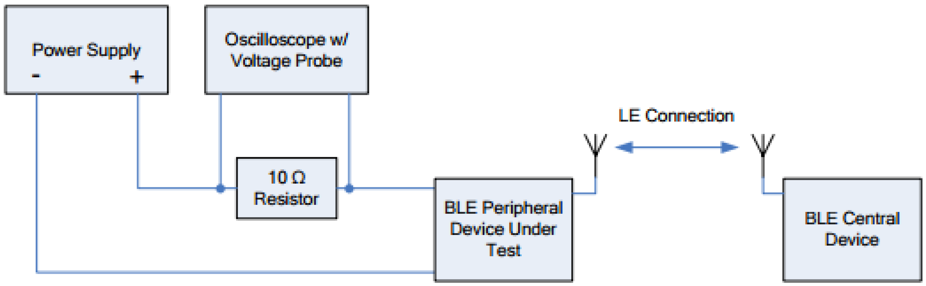
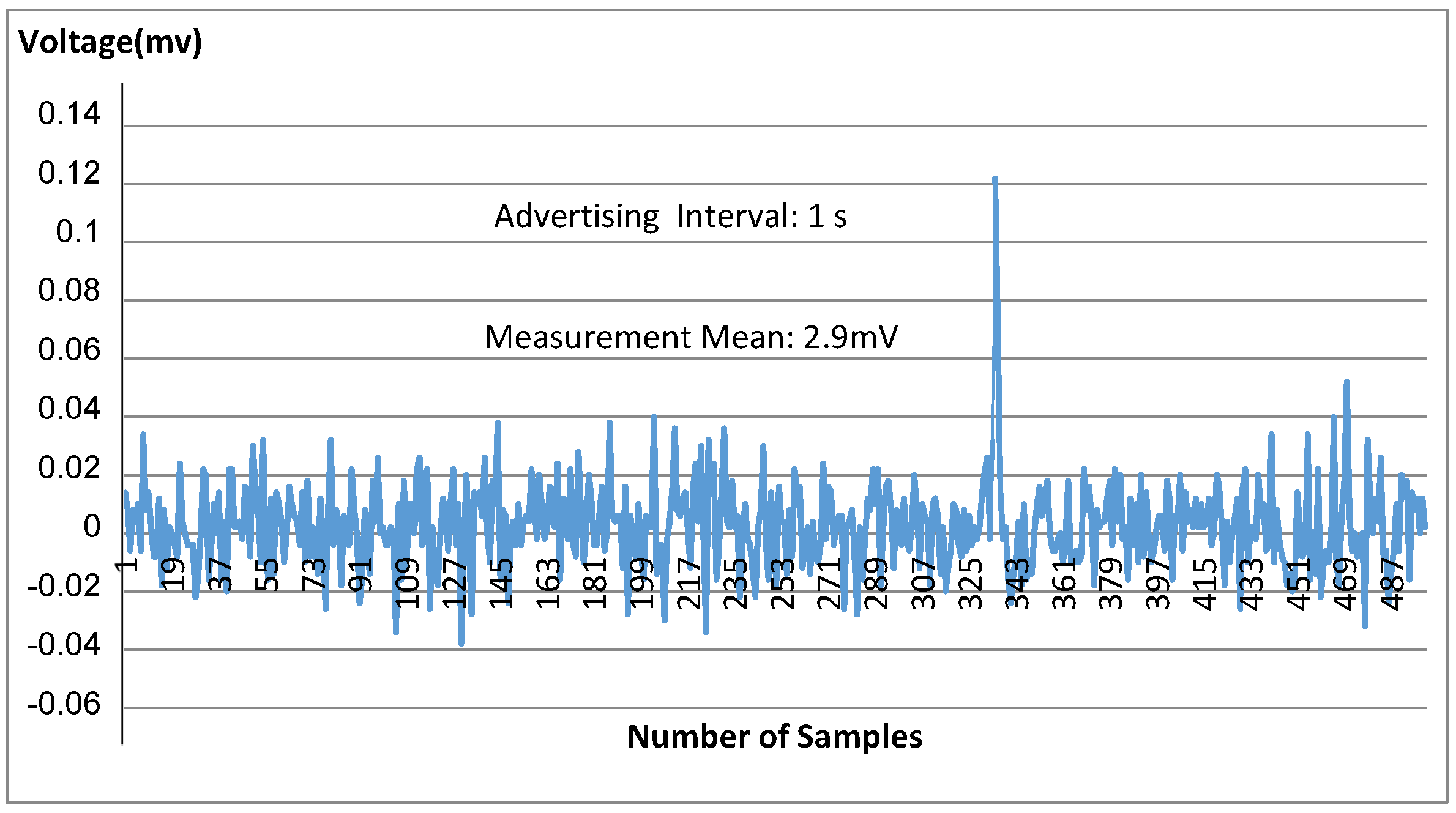
3.6. Current Consumption

The primary metric that takes all time and current measurements into account is the “average current”. This value can be used to determine the battery life of a device running the BLE stack.
The following parameters should be taken into consideration regarding the current consumption calculation:
(i) For current consumption during advertising calculation:
  • Advertising interval;
  • Amount of advertising payload data in bytes for each advertising packet;
  • Continuous advertising or periodical advertising;
  • Transmitter power.
(ii) For current consumption during scanning calculation:
  • Connection interval;
  • Slave latency;
  • Receive (RX) payload in each packet;
  • Transmit (TX) payload in each packet.

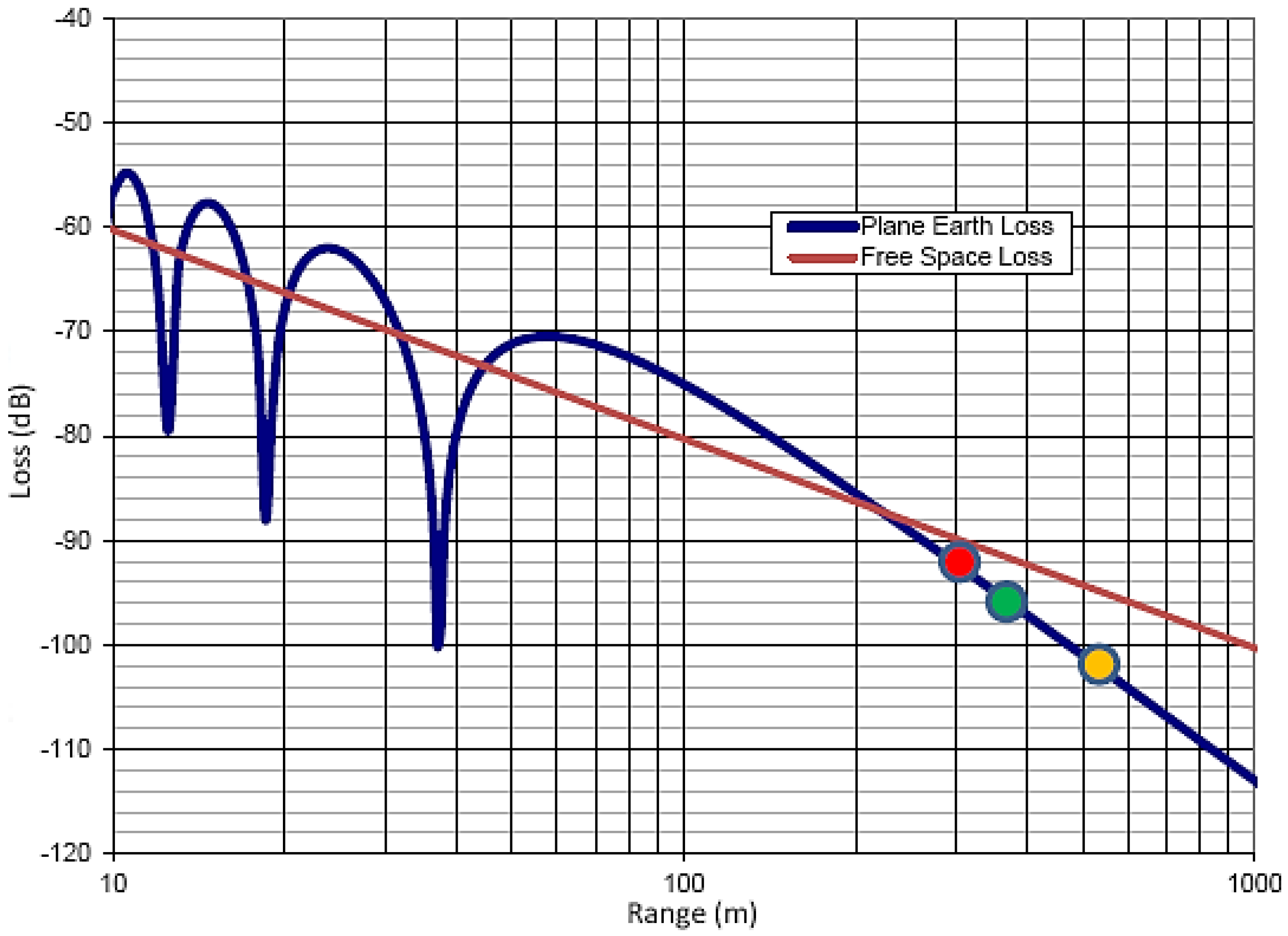
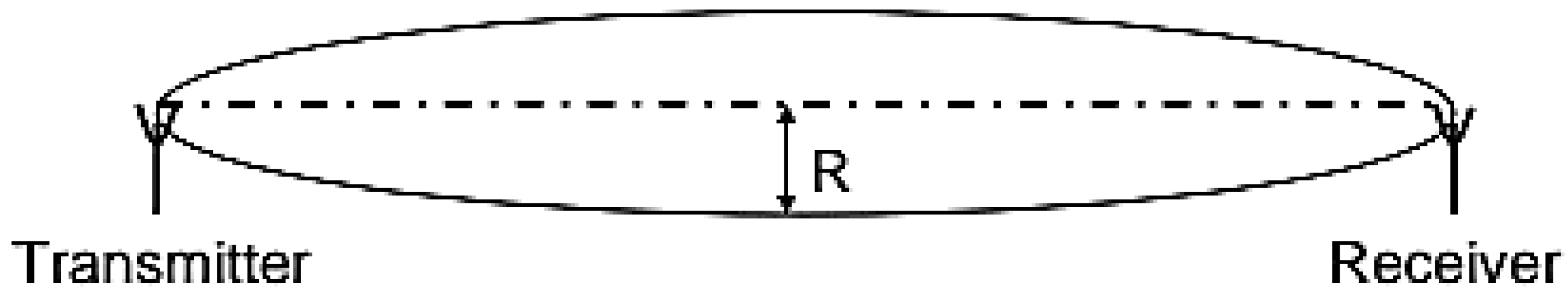
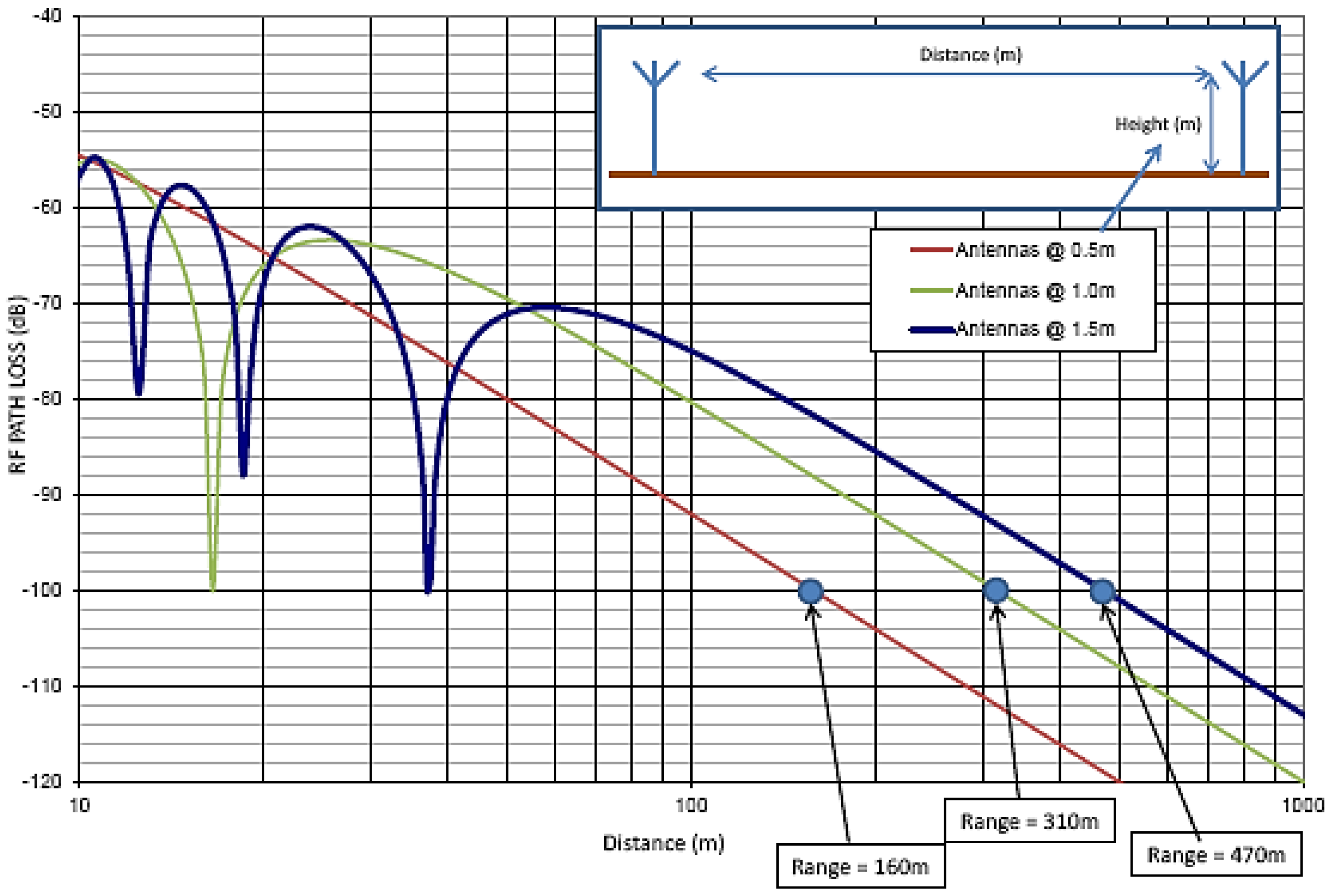
3.7. Range Calculation

Radio Frequency (RF) power propagates in free space within a virtual “pipe” (Figure 8), which can be defined by the so-called Fresnel ellipsoid. Any obstacles within the area of this “pipe” attenuate the RF power and thus decrease the actual range of the link. The radius of the “pipe” can be approximated by:
R = D λ 12 ,
where R is the radius, D is the distance between the antennas and λ is the wave length
The free space loss can be approximated by:
P a t h   L o s s   d B   = 92.45 + 20 log f + 20 log d ,
where f is frequency in GHz and d is distance in kilometers. This approximation however does not apply to the actual case where the signal is reflected from the ground. More realistic results can be calculated by using (3):
P R P T = 2 λ 4 π r 2 1 c o s k 2 h 1 h 2 r ,
where PR and PT represent the received signal power and transmitted power, respectively, h1 and h2 denote the heights of the two antennas, k is the free space wave number and r stands for the distance between the two antennas. The equation is expressed with the blue line (BlueGiga [46]) in Figure 9 showing the Plane Earth Loss.
The distance dm where the ground starts to become influential can be calculated by:
d m = 12 · h 1 · h 2 λ ,
The total range can be approximated once the output power from the antenna (transmitter output power + antenna gain) and the receiver sensitivity (receiver sensitivity + antenna gain) is defined. As an example, by using antenna heights equal to 1 m, 2 m and 3 m, TX power equal to 3 dBm, receiver sensitivity equal to −91 dBm and antenna attenuation equal to 5 dB (where 5 dB is the loss in both TXP and RX sensitivity) one can approximate the total ranges assuming an open field without obstacles within the RF path as follows:
h = 1 m → D = 125 m
h = 2 m → D = 235 m
h = 3 m → D = 305 m
BLE Range Analysis [47] describes the methodology for the BLE coverage distance evaluation. In a practical application, the range can be much shorter because the orientation and height of the antenna cannot be controlled, and typically, there are also obstacles within the RF path which will significantly attenuate the signal. In practical applications, the range is impacted by:
  • Persons/obstacles moving close to the antenna. This is due to multipath propagation and will have an impact even if the person is not in the line of sight between the two radios.
  • Any obstacles within the radio path.
  • Transmitting antenna gain and height.
  • The mechanical design of the end product.
As the range is impacted by many factors which are difficult to control, the practical range must be tested with the end product, and the application should not be design based on the maximum theoretical range as the practical range will always be shorter.
Next, it is shown how the transmit power, receiver sensitivity and radiation pattern convert to the link budget and how the line of sight range can be estimated using a plane earth loss calculation. Additionally, the practical test results are shown in comparison with the theoretical estimate.
The results of the experimental measurements performed in an open field, regarding the practical line of sight range of the BLE121 long range module, manufactured by BlueGiga [46], with antennas positioned at 1.5 m above ground, using the heart rate example [48], are shown in Table 1, where the range represents the distance at which the remote device remains able to still connect and maintain the connection to the module.
The tests performed took place in an airfield using a data connection between the modules, while, as mentioned above, the result does not guarantee a practical range for real application. Measurement results regarding the transmission range obtained for the BLE121LR module, along with the calculated ones, are shown in Table 2. The calculated results were obtained following the equations presented in previous subsections, while it is considered that the transmit power is equal to +8 dBm and the receiver sensitivity is equal to −98 dBm. The examination of these BLE results indicates that the tested range can surpass 300 m and increase up to 450 m depending on the antenna orientation and attenuation.
Additional measurement tests were carried out with an antenna height equal to 0.5 m, 1 m and 1.5 m, as illustrated in Figure 10. The investigation of this figure indicates that, by setting the antenna height to 1.5 m, the coverage range can be extended up to 470 m.

3.8. BLE Range Test Definition and Use Case Scenarios

As antenna gain parameters can have a substantial impact on maximizing distance, it was decided to carry out measurement using +2.5 dBi (Figure 11) and +9 dBi (Figure 12) external antennas, connected to a IBLio module used with Gateway.
The maximum Tx power from the module was +3 dBm [49], but a loss of 2 dB on the connections was considered, so that the target had the maximum allowable transmit power on the external antenna at +13 dBm, as indicated for use in Europe.
In Figure 13 iBLio BLE module connection with 2 dBi antenna is depicted.
The hardware units used for range test are as follows:
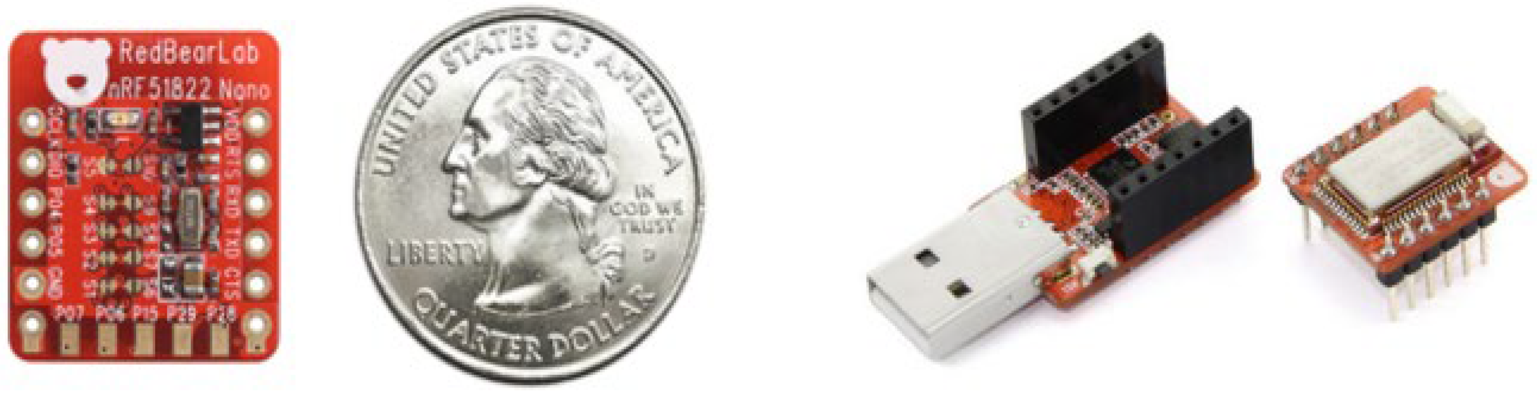
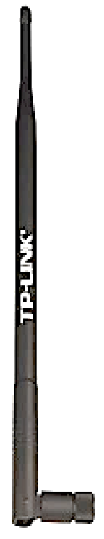
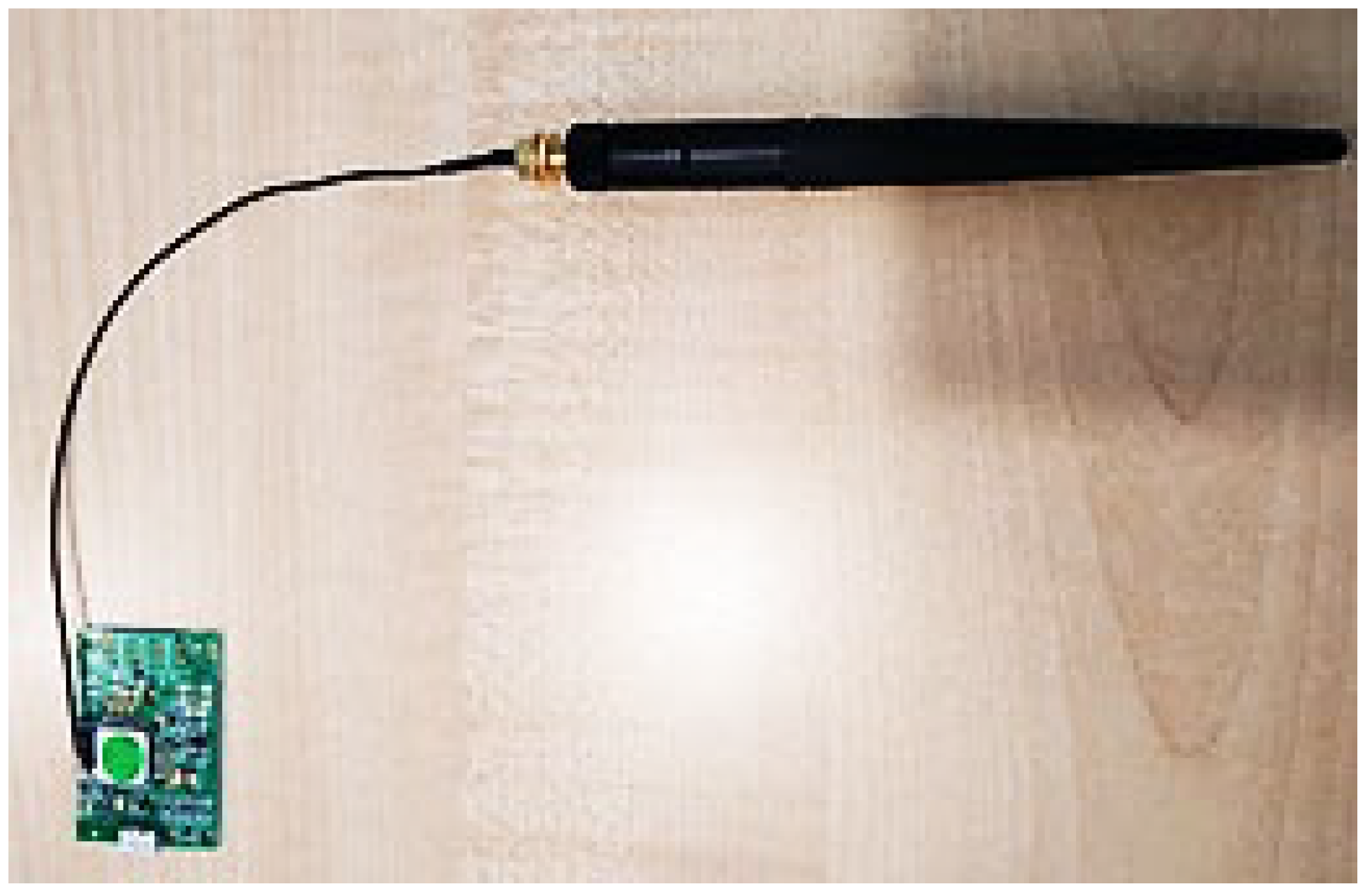
  • iBLio BLE/USB G03 unit with either 2 dBi or 9 dBi antenna connected to laptop USB port.
  • RedBear nano-BLE tag with CRC2032 battery.
  • Android Mobile phone to test and validate signal level.
The test procedure is as follows:
  • High/low antenna gain connection to BLE module.
  • Configuration of BLE Tx power level and custom device name.
  • Confirmation that custom device name is properly transmitted.
  • Activation of BLE tag device and arrangement of it to be in observer mode. This ensures that data can be received by the test device.
  • Separation of the two devices until BLE nanomode can be marginally modified.
  • Recording of the previous mentioned location.
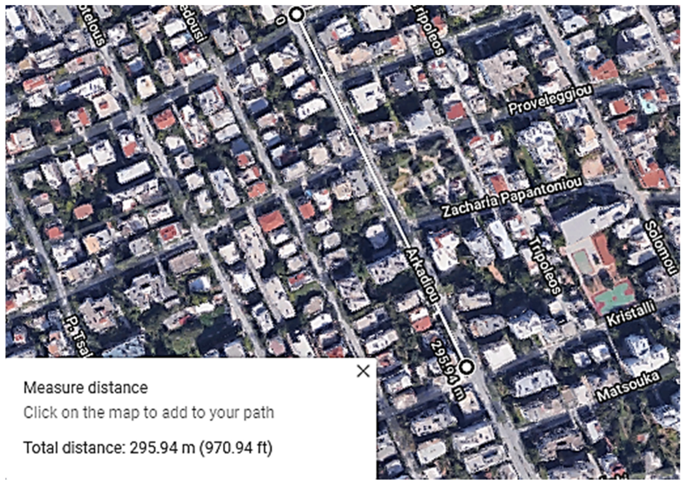
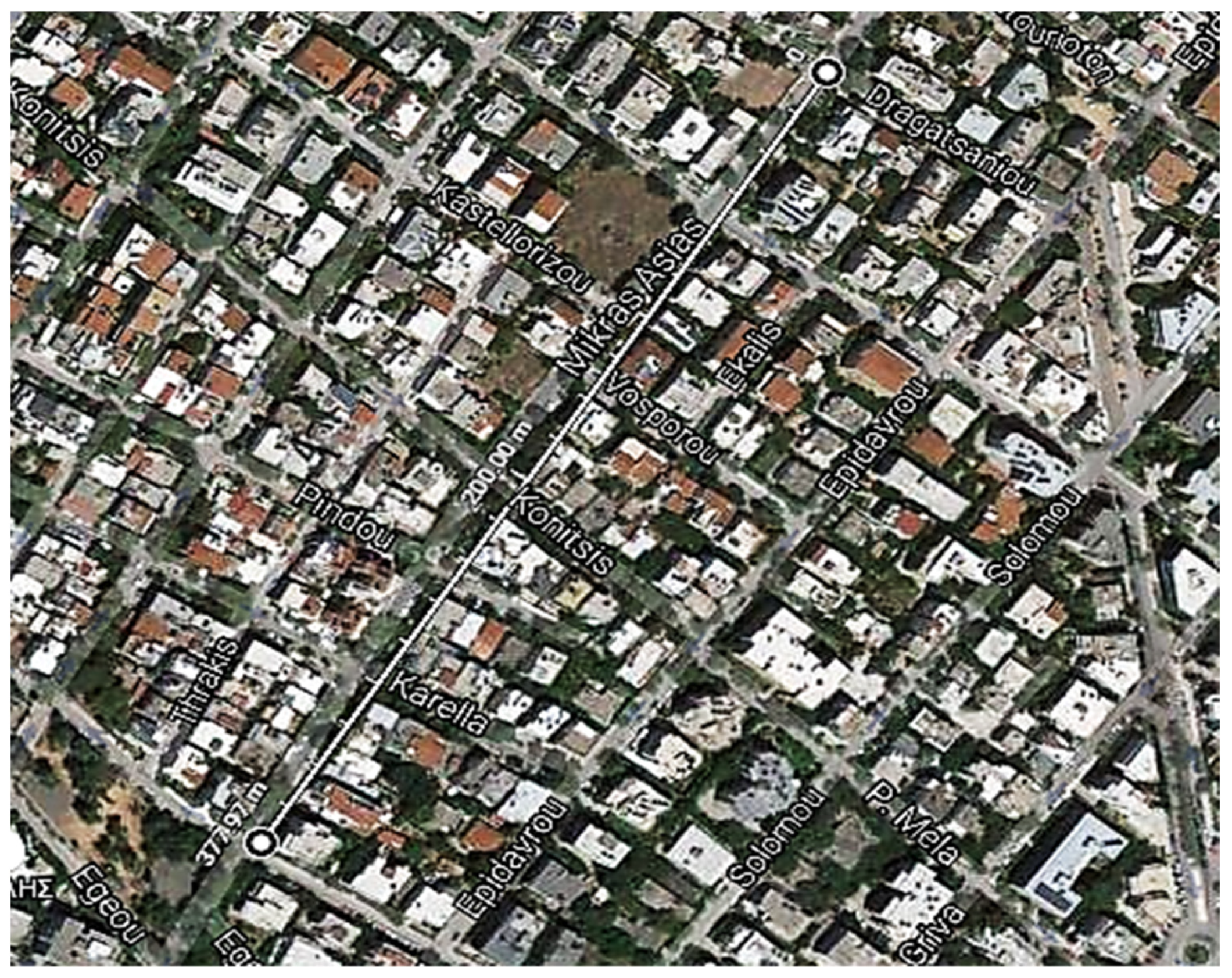
  • Use of geographical information software (in this case Google Earth), to measure the range of the connection.
  • Repetition of the experiment by using different antenna heights.
The iBLio BLE module sustained connectivity with each device to varying ranges before the connection was lost.

4. Performance Evaluation and Discussion

During the experimental tests performed it was considered that line of sight or partial line of sight were maintained for the range test. The most adverse condition was the likely presence of few Wi-Fi networks in the area and vehicles travelling along the street.
Actual results for many applications may vary. However, the test performed demonstrates that it is possible to maintain a range of up to 300 m, far greater than the range of most modern Bluetooth applications.
In Figure 14 and Figure 15 the topology of measurement points in a typical urban area is illustrated.
The range of the BLE activation distance was tested by increasing the distance between the BLE tag and the BLE/Wi-Fi gateway until communication was no longer possible. The range was determined for different transmitting powers ranging from 0 dBm to +3 dBm with the results shown in Table 3.
Using an alternative antenna, other than that provided by the chip, could help to extend the range of the device; using printed circuit board (PCB) antennas of larger sizes could improve the achievable range. In almost all measurement tests, the coverage distance was measured in mainly line of sight conditions.
Additionally, changes could be made to the layout of the PCB, to increase the distance from the copper plating and the antenna, however, this would require the size of the node to increase. The range could be potentially extended by using a point-to-point network with repeaters.
Current consumption during advertising mainly depends on the advertising interval, which is adjusted by modifying the relevant parameter. Practically, in order to save current, t the device should advertise periodically and not continuously. The measurement setup that was used for measuring the current is schematically shown in Figure 16, while the lab devices are depicted in Figure 17 and the measurements diagram is illustrated in Figure 18.
It was found that current consumption was approximately equal to 36 mA, which is quite close to the value found by the device manufacturer [50] regarding current consumption in advertising mode with advertising interval 1000 ms, 31 bytes payload, and 4 dBm output power.
In order to reliably evaluate the effectiveness of the proposed sensor platform, to fine tune sensor/smartphone software parameters, and to evaluate the overall performance of the system proposed, a two months pilot survey with several participants was conducted at certain pilot sites [35].
Specifically, the City.Risks consortium has organized two test sessions in two capital cities (i.e., Rome and Sofia) to check the functionality of the proposed system in real environments [51].
The tests performed in Rome, took place in December 2017 in Circo Massimo and in Aventino. First, in Circo Massimo, which is an area free of buildings, a small group of citizens was involved in the test, together with representatives of the Municipal Police and some members of the City.Risks consortium. Specifically, there were four different teams of participants in the field: the “victims of theft”, the “thieves”, the “policemen” and the “community activists”. The City.Risks Operation Center was established at the Municipal Police headquarters of Rome. In the tests performed, the first type of participants were equipped with some BLE sensors, previously registered on their smartphones and started wandering around in the area. After a while, they were approached by some of the second type of participants, who “stole” the BLE tags and moved away. The thefts were reported to the members of the Operation Center, who activated the stolen tags so that they could be tracked by the community activists. The pieces of information collected by the smartphones were sent to the Operation Center and eventually the policemen “arrested” the “thieves” and retrieved the stolen tags. Next, in the Aventino residential area, the same scenario was executed to simulate the effect of blocking buildings on the BLE signals. Once again, the “stolen” tags were retrieved.
The pilot tests conducted in Sofia, took place in February 2018 inside The Mall shopping center. In these tests some citizens participated playing all of the aforementioned roles. Three gateways were placed in different locations inside the mall, to detect the stolen tags. These pilot tests gave the opportunity to evaluate the functionality of the system indoors.
In the final stages of development, the adopted scenario considers a bicycle as a personalized item that must be protected. A BLE tag is mounted under the bicycle seat to prevent it from getting wet and/or being noticed. Similar to other antitheft systems, where removing the tag may render tracking ineffective, ways to address this issue include hiding the tag more effectively, increasing the difficulty of removing the tag, (i.e., welding) or integrating the tag into a bike lock. The user registers the sensor with the authorities. Once the bicycle is identified to be missing, the user informs the authorities about the theft. The responsible authority, using the developed appropriate infrastructure, remotely activates the sensor from its conventional mode by multicasting a short-range signal that triggers the sensor to periodically broadcast emergency signals to mobile devices in proximity. Theft travels a predefined route passing through mobile users at the side of the street with the smartphone application. The signal broadcasted by the sensor is picked up by a mobile device with the City.Risks mobile application installed, and the authorities are notified by the application that the stolen item has been located.
The trial tests conducted proved that the system is effective in:
  • Receiving theft incident reports along with the stolen device unique identifier (UID).
  • Notifying the Mobile apps and the Gateways to initiate the activation process of the stolen device, and also providing them with the stolen device UID. This is the most innovative feature of the entire solution. The user can set the BLE sensor to remain at receiver only mode so as to prevent BLE transmission which could trigger the potential theft to remove or destroy the sensor if the thief’s mobile phone is notified by the sensor beacon signal.
  • Receiving an activation report from either the mobile app or the gateway that activated the stolen device.
  • Letting the gateway capture the signal and inform the Authorities once the sensor switches from receiver to beacon mode.
  • Notifying both the gateways and the mobile apps to start scanning once the stolen device is activated.
  • Triggering, nearby Gateways to start scanning the sensor which is in beacon mode
  • Notifying the mobile apps to switch to inactive mode and stop scanning when the stolen device has been retrieved.

5. Future Work

The design of the theft detection sensor was tested and evaluated within specific framework scenarios to validate that all functional requirements are successfully met. Optimization of sensor design principally involves battery consumption optimization schemes, longer distance coverage and mobile application improvement. BLE5.0 technology [52] features could be exploited as well as coupling of BLE device with RF LoRA-based networks [53]. Optimum design of operation as well as the improvement on software development of application structural logic are among core tasks for further development in future work.

6. Conclusions

This paper presented a smart IoT-based participatory sensing and alerting system that was developed under the City.Risks project. The specific system uses everyday mobile phones and BLE technology to identify and locate stolen objects within a specific urban range. Specifically, an innovative, small and discrete sensor was designed and implemented coupling BLE and radio-based technologies to be used along with the City.Risks network. BLE/Wi-Fi gateways and smartphones of the community users are used to forward the wake-up signals to the BLE devices that are attached to the mobile assets. Therefore, City.Risks application users are able to locate stolen assets and accordingly notify a centralized server via their smart phones running a BLE scanning application. The system, despite its low cost, was thoroughly tested and proven to be effective to provide authorities modern technological means to provide better services and governance regarding public safety in urban environments.
The use of systems such as the one discussed herein can make cities safer and feel safer with the active participation of citizens in online communities that support the sharing of information for the common benefit. However, the use of advanced technological means is not adequate by itself to reform existent urban settlements into cities that are not only smart but also sustainable, without additionally applying appropriate practices in terms of community behavior and governmental policies [54].

Author Contributions

Conceptualization, N.P. and I.S.; methodology, I.S., I.C., D.K., N.P. and N.K.; software, N.P. and N.K.; validation, I.S., D.K. and N.P.; formal analysis, N.K.; investigation, I.S., I.C., D.K., N.P. and N.K.; resources, I.S., I.C., D.K., N.P. and N.K.; data curation, N.P. and N.K.; writing—original draft preparation, I.C., N.P. and N.K.; writing—review and editing, I.S. and D.K.; visualization, N.K. and N.P.; supervision, I.S., I.C., D.K., N.P. and N.K.; project administration, N.P.; funding acquisition N.P. All authors have read and agreed to the published version of the manuscript.

Funding

This research work was financed by the European Union through the Horizon 2020 City.Risks project (ID 653747) entitled “Avoiding and mitigating safety risks in urban environments” under call FCT-10-2014—Urban security topic 1: Innovative solutions to counter security challenges connected with large urban environment.

Institutional Review Board Statement

Not applicable.

Informed Consent Statement

Informed consent was obtained from all subjects involved in the study.

Data Availability Statement

No new data were created or analyzed in this study. Data sharing is not applicable to this article.

Conflicts of Interest

The authors declare no conflict of interest. The funders had no role in the design of the study; in the collection, analyses, or interpretation of data; in the writing of the manuscript, or in the decision to publish the results.

References

  1. Mealey, L. The sociobiology of sociopathy: An integrated evolutionary model. Behav. Brain Sci. 1995, 18, 523–541. [Google Scholar] [CrossRef] [Green Version]
  2. Insurance Information Institute. Available online: https://www.iii.org/fact-statistic/facts-statistics-auto-theft#Motor%20Vehicle%20Theft,%202010-2019 (accessed on 30 March 2021).
  3. Van Dijk, J.J.M.; Van Kesteren, J.N.; Smit, P. Criminal Victimization in International Perspective, Key Findings from the 2004–2005 ICVS and EU ICS; Boom Legal Publishers: Den Haag, The Netherlands, 2008; pp. 257–258. [Google Scholar]
  4. Hom, E.J. Mobile Device Security: Startling Statistics on Data Loss and Data Breaches. 2017. Available online: http://www.channelpronetwork.com/article/mobile-device-security-startling-statistics-data-loss-anddata-breaches (accessed on 7 March 2021).
  5. Zhang, L.; Messner, S.F.; Liu, J. Bicycle-Theft Victimization in Contemporary Urban China, A Multilevel Assessment of Risk and Protective Factors. J. Res. Crime Delinq. 2007, 44, 406–426. [Google Scholar] [CrossRef]
  6. Goonetilleke, A.; Yigitcanlar, T.; Ayoko, G.; Egodawatta, P. Sustainable Urban Water Environment: Climate, Pollution and Adaptation; Edward Elgar: Cheltenham, UK, 2014. [Google Scholar]
  7. Lara, A.; Costa, E.; Furlani, T.; Yigitcanlar, T. Smartness that matters: Comprehensive and human-centred characterisation of smart cities. J. Open Innov. Technol. Mark. Complex. 2016, 2, 1–13. [Google Scholar] [CrossRef] [Green Version]
  8. Yigitcanlar, T.; Hoon, M.; Kamruzzaman, M.; Ioppolo, G.; Sabatini-Marques, J. The making of smart cities: Are Songdo, Masdar, Amsterdam, San Francisco and Brisbane the best we could build? Land Use Policy 2019, 88, 104187. [Google Scholar] [CrossRef]
  9. Trindade, E.P.; Hinnig, M.P.F.; Da Costa, E.M.; Marques, J.S.; Bastos, R.C.; Yigitcanlar, T. Sustainable development of smart cities: A systematic review of the literature. J. Open Innov. Technol. Mark. Complex. 2017, 3, 11–14. [Google Scholar] [CrossRef] [Green Version]
  10. Zawieska, J.; Pieriegud, J. Smart city as a tool for sustainable mobility and transport decarbonisation. Transp. Policy 2018, 63, 39–50. [Google Scholar] [CrossRef]
  11. Kandris, D.; Nakas, C.; Vomvas, D.; Koulouras, G. Applications of Wireless Sensor Networks: An Up-to-Date Survey. Appl. Syst. Innov. 2020, 3, 14. [Google Scholar] [CrossRef] [Green Version]
  12. Zantalis, F.; Koulouras, G.; Karabetsos, S.; Kandris, D. A Review of Machine Learning and IoT in Smart Transportation. Future Internet 2019, 11, 94. [Google Scholar] [CrossRef] [Green Version]
  13. Ejaz, W.; Anpalagan, A. Internet of Things for Smart Cities: Overview and Key Challenges. In Internet of Things for Smart Cities: Technologies, Big Data and Security; Springer International Publishing: Cham, Switzerland, 2019; pp. 1–15. [Google Scholar]
  14. Memos, V.A.; Psannis, K.E.; Ishibashi, Y.; Kim, B.G.; Gupta, B. An Efficient Algorithm for Media-based Surveillance System (EAMSuS) in IoT Smart City Framework. Future Gener. Comput. Syst. 2017. [Google Scholar] [CrossRef]
  15. Alazab, M.; Lakshmanna, K.; Reddy, T.; Pham, Q.V.; Maddikunta, P.K.R. Multi-objective cluster head selection using fitness averaged rider optimization algorithm for IoT networks in smart cities. Sustain. Energy Technol. Assess. 2021, 43, 100973. [Google Scholar]
  16. Kandris, D.; Alexandridis, A.; Dagiuklas, T.; Panaousis, E.; Vergados, D.D. Multiobjective Optimization Algorithms for Wireless Sensor Networks. Wirel. Commun. Mob. Comput. 2020, 1, 1–5. [Google Scholar] [CrossRef]
  17. Mahesh, R.P.; Imdad, R. IoT Based Embedded System for Vehicle Security and Driver Surveillance. In Proceedings of the 2nd International Conference on Inventive Communication and Computational Technologies (ICICCT 2018), Coimbatore, India, 20–21 April 2018; pp. 466–470. [Google Scholar]
  18. Raj, C.; Rajkumar, S.M. Design of a Low Cost GSM Based Embedded System for Preventing Vehicle Theft Using AVR Microcontroller. J. Sib. Fed. Univ. Eng. Technol. 2020, 13, 63–68. [Google Scholar]
  19. Vivek, K.S.; Soumitra, M.; Harshit, M. Car Security using Internet of Things. In Proceedings of the 1st IEEE International Conference on Power Electronics Intelligent Control and Energy Systems (ICPEICES-2016), Delhi, India, 4–6 July 2016; pp. 1–5. [Google Scholar]
  20. Ramadan, M.; Al-Khedher, M.; Al-Kheder, S. Intelligent anti-theft and tracking system for automobiles. Int. J. Mach. Learn. Comput. 2012, 2, 83. [Google Scholar] [CrossRef]
  21. Al-Hindawi, A.M.J.; Talib, I. Experimentally Evaluation of GPS/GSM Based System Design. J. Electron. Syst. 2012, 2, 67. [Google Scholar]
  22. Guorui, Z.; Dai, S. Design of auto guard against theft system based on GPRS and GPS. Microcontroll. Embed. Syst. 2007, 8, 39–41. [Google Scholar]
  23. Fasiuddin, S.; Omer, S.; Sohelrana, K.; Tamkeen, A.; Rasheed, M.A. Real Time Application of Vehicle Anti Theft Detection and Protection with Shock Using Facial Recognition and IoT Notification. In Proceedings of the 2020 Fourth International Conference on Computing Methodologies and Communication (ICCMC), Erode, India, 11–13 March 2020; pp. 1039–1044. [Google Scholar]
  24. Das, D.; Banerjee, S.; Ghosh, U.; Biswas, U.; Bashir, A.K. A decentralized vehicle anti-theft system using Blockchain and smart contracts. Peer-to-Peer Netw. Appl. 2021, 1–14. [Google Scholar] [CrossRef]
  25. Guo-Cheng, L.; Hong-Yang, Y. Design and implementation of a Bluetooth 4.0-based heart rate monitor system on iOS platform. In Proceedings of the 2013 International Conference on Communications, Circuits and Systems (ICCCAS), Chengdu, China, 15–17 November 2013; pp. 112–115. [Google Scholar]
  26. Arvanitopoulos, A.; Gialelis, J.; Koubias, S. Energy efficient indoor localization utilizing BT 4.0 strapdown inertial navigation system. In Proceedings of the 2014 IEEE Emerging Technology and Factory Automation (ETFA), Barcelona, Spain, 16–19 September 2014; pp. 1–5. [Google Scholar]
  27. Liu, J.; Chen, C.; Ma, Y.; Xu, Y. Energy Analysis of Device Discovery for Bluetooth Low Energy. In Proceedings of the 2013 IEEE 78th Vehicular Technology Conference (VTC Fall), Las Vegas, NV, USA, 2–5 September 2013; pp. 1–5. [Google Scholar]
  28. Siekkinen, M.; Hiienkari, M.; Nurminen, J.K.; Nieminen, J. How low energy is bluetooth low energy? Comparative measurements with ZigBee/802.15.4. In Proceedings of the 2012 IEEE Wireless Communications and Networking Conference Workshops (WCNCW), Paris, France, 1 April 2012; pp. 232–237. [Google Scholar]
  29. Koodtalang, W.; Sangsuwan, T. Improving motorcycle anti-theft system with the use of Bluetooth Low Energy 4.0. In Proceedings of the 2016 International Symposium on Intelligent Signal Processing and Communication Systems (ISPACS), Phuket, Thailand, 24–27 October 2016; pp. 1–5. [Google Scholar]
  30. City.Risks Project Overview, Objectives. Available online: http://project.cityrisks.eu/project-overview/ (accessed on 17 March 2021).
  31. Bluetooth Low Energy. Available online: https://www.bluetooth.com/learn-about-bluetooth/radio-versions/ (accessed on 29 March 2021).
  32. Townsend, K.; Cufí, C.; Davidson, R. Getting Started with Bluetooth Low Energy: Tools and Techniques for Low-Power Networking, 1st ed.; O’Reilly Media Inc.: Sebastopol, CA, USA, 2014; pp. 1–4. [Google Scholar]
  33. Du, J.; Chao, S. A study of information security for M2M of IOT. In Proceedings of the 3rd International Conference on Advanced Computer Theory and Engineering (ICACTE), Chengdu, China, 20–22 August 2010; p. V3-576. [Google Scholar]
  34. Wu, G.; Talwar, S.; Johnsson, K.; Himayat, N.; Johnson, K.D. M2M: From mobile to embedded internet. IEEE Commun. Mag. 2011, 49, 36–43. [Google Scholar]
  35. City.Risks Deliverable D2.4 Use Case Requirements and Key Performance Indicators. Available online: http://project.cityrisks.eu/wp-content/uploads/deliverables/CityRisks_D2.4-Use%20Cases,-Requirements-and-Key-Performance-Indicators.pdf (accessed on 17 March 2021).
  36. Starsinic, M. System architecture challenges in the home M2M network. In Proceedings of the 2010 IEEE Long Island Systems, Applications and Technology Conference, Farmingdale, NY, USA, 7 May 2010; pp. 1–7. [Google Scholar]
  37. Lee, C.T.; Chang, C.M.; Kao, C.Y.; Tseng, H.M.; Hsu, H.; Nien, C.C.; Chen, L.H.; Lai, L.Y.; Chiu, T.C.; Chou, P.H. Smart Insulating Container with Anti-theft Features by M2M Tracking. In Proceedings of the 2014 IEEE International Conference on Internet of Things (iThings), and IEEE Green Computing and Communications (GreenCom) and IEEE Cyber, Physical and Social Computing (CPSCom), Taipei, Taiwan, 1–3 September 2014; pp. 140–147. [Google Scholar]
  38. Rao, M.; Newe, T.; Grout, I. Secure Hash Algorithm-3(SHA-3) implementation on Xilinx FPGAs, Suitable for loT Applications. In Proceedings of the 8th International Conference on Sensing Technology, Liverpool, UK, 2–4 September 2014; Volume 7. [Google Scholar]
  39. Pinto, A.; Costa, R. Hash-Chain-Based Authentication for Iot. Adv. Distrib. Comput. Artif. Intell. J. 2015, 3, 1–16. [Google Scholar] [CrossRef] [Green Version]
  40. RedBearLabBLE Nano. Available online: https://os.mbed.com/platforms/RedBearLab-BLE-Nano/ (accessed on 17 March 2021).
  41. nRF51822 Bluetooth Smart Beacon Kit. Available online: https://www.nordicsemi.com/Software-and-tools/Reference-Designs/nRF51822-Beacon-Kit/GetStarted (accessed on 17 March 2021).
  42. Laird Bluetooth Modules. Available online: https://www.lairdtech.com/product-categories/connectivity-solutions/bluetooth-modules (accessed on 17 March 2021).
  43. Cypress Technologies PSoC 4 Bluetooth Low Energy Compliant Pioneer Kit. Available online: http://www.cypress.com/documentation/development-kitsboards/cy8ckit-042-ble-bluetooth-low-energy-ble-pioneer-kit (accessed on 17 March 2021).
  44. Jin, M.; He, Y.; Fang, D.; Chen, X.; Meng, X.; Xing, T. iGuard: A Real-Time Anti-Theft System for Smartphones. IEEE Trans. Mob. Comput. 2018, 17, 2307–2320. [Google Scholar] [CrossRef]
  45. Pezoa, F.; Reutter, J.; Suarez, F.; Ugarte, M.; Vrgoč, D. Foundations of JSON Schema. In Proceedings of the 25th International Conference on World Wide Web, Montreal, QC, Canada, 11–15 April 2016; pp. 263–273. [Google Scholar]
  46. Silicon Labs. BLE112. Available online: https://www.silabs.com/documents/public/data-sheets/BLE112-DK-DataSheet.pdf/ (accessed on 17 March 2021).
  47. Silicon Labs. BLE112, BLE113 and BLE121LR Range Analysis. Available online: https://www.silabs.com/documents/public/application-notes/AN985.pdf (accessed on 17 March 2021).
  48. Silabs AN983: Bluetooth® 4.0 Heart Rate Sensor Application Note. Available online: https://www.silabs.com/documents/public/application-notes/AN983-Bluetooth-4.0-Heart-Rate-Sensor.pdf (accessed on 27 March 2021).
  49. Bluetooth Smart Module Configuration Guide, Version 31. Available online: https://www.scribd.com/document/269277579/Bluetooth-Smart-Configuration-Guide-v31 (accessed on 27 March 2021).
  50. Lower Power Mode Nordic nRF51822. Available online: https://developer.mbed.org/questions/4693/Lower-power-Mode-Nordic-nRF51822/ (accessed on 27 March 2021).
  51. Major Cities of Europe IT Users Group. Available online: https://www.majorcities.eu/misc/eu-projects/city-risks/ (accessed on 15 May 2021).
  52. Wang, X.; Büsze, B.; Vandecasteele, M.; Liu, Y.H.; Bachmann, C.; Philips, K. The design challenges of IoT: From system technologies to ultra-low power circuits. IEICE Trans. Electron. 2017, 100, 515–522. [Google Scholar] [CrossRef] [Green Version]
  53. Raza, U.; Kulkarni, P.; Sooriyabandara, M. Low Power Wide Area Networks: An Overview. IEEE Commun. Surv. Tutor. 2017, 19, 855–873. [Google Scholar] [CrossRef] [Green Version]
  54. Yigitcanlar, T.; Kamruzzaman, M.; Foth, M.; Sabatini-Marques, J.; da Costa, E.; Ioppolo, G. Can cities become smart without being sustainable? A systematic review of the literature. Sustain. Cities Soc. 2019, 45, 348–365. [Google Scholar] [CrossRef]
Figure 1. Graphical overview of the architecture of City.Risks platform.
Smartcities 04 00047 g001
Figure 2. Basic architecture of the BLE antitheft device activation.
Smartcities 04 00047 g002
Figure 3. Antitheft BLE device and development board.
Smartcities 04 00047 g003
Figure 4. BLE tag device modes.
Smartcities 04 00047 g004
Figure 5. Antitheft tag workflow chart.
Smartcities 04 00047 g005
Figure 6. Mobile phone message transaction scheme with REST Endpoint.
Smartcities 04 00047 g006
Figure 7. Gateway operational workflow.
Smartcities 04 00047 g007
Figure 8. Transmit receive antenna configuration.
Smartcities 04 00047 g008
Figure 9. Planet earth loss and free space loss diagrams.
Smartcities 04 00047 g009
Figure 10. Antenna height effect on BLE range.
Smartcities 04 00047 g010
Figure 11. STILO 2.4 GHz SMS/M FLES 2.5 dBi gain antenna.
Smartcities 04 00047 g011
Figure 12. TL ANT2409A 9 dBi gain antenna.
Smartcities 04 00047 g012
Figure 13. iBLio BLE module connected with 2 dBi gain antenna.
Smartcities 04 00047 g013
Figure 14. Antenna gain: 2.5 dBi; height: 1.5 m; BLE range: ≈296 m.
Smartcities 04 00047 g014
Figure 15. Antenna gain: 9 dBi; height: 5 m; BLE range: ≈378 m.
Smartcities 04 00047 g015
Figure 16. Antenna gain: 9 dBi; height: 5 m; BLE range: 377 m.
Smartcities 04 00047 g016
Figure 17. Schematic diagram of measurement procedure setup.
Smartcities 04 00047 g017
Figure 18. Test setup using oscilloscope with voltage probe.
Smartcities 04 00047 g018
Table 1. Practical ranges tested.
SetupPractical Line of Sight Range Tested
BLE121LR vs. iPod250 m–300 m
BLE121LR vs. Nexus7~430 m
BLE113 vs. iPod60 m–80 m
Table 2. Ranges for BLE121LR tested.
DirectionAntenna Attenuation (dB)Link Budget (dB)Range Calculated (m)Range Tested (m)
Front−3100470450
Back−792300300
Side−596370340
Table 3. BLE distance range measurements.
Antenna TypeTransmit Power (dBm)Antenna Height (m)Distance Reached (m)
2.5 dBi31.5295
5310
9 dBi31.5350
5377
Publisher’s Note: MDPI stays neutral with regard to jurisdictional claims in published maps and institutional affiliations.

