Article

Electric Vehicle Integration into Road Transportation, Intelligent Transportation, and Electric Power Systems: An Abu Dhabi Case Study

1
Thayer School of Engineering, Dartmouth College, Hanover, NH 03755, USA
2
Mechanical Engineering Department, Massachusetts Institute of Technology, Cambridge, MA 02139, USA
3
Department of Aerospace, School of Engineering, Main Campus, Khalifa University of Science and Technology, Abu Dhabi P.O. Box 127788, United Arab Emirates
4
Hub71, Abu Dhabi P.O. Box 764624, United Arab Emirates
5
T3 Design, Fairfax, VA 22030, USA
6
NAVARA, 3972 LK Driebergen-Rijsenburg, The Netherlands
*
Author to whom correspondence should be addressed.
Submission received: 14 May 2021 / Revised: 29 June 2021 / Accepted: 30 June 2021 / Published: 23 July 2021
(This article belongs to the Section Smart Urban Infrastructures)

Abstract

:
Recently, electric vehicles (EV) have gained much attention as a potential enabling technology to support CO 2 emissions reduction targets. Relative to their internal combustion vehicle counterparts, EVs consume less energy per unit distance, and add the benefit of not emitting any carbon dioxide in operation and instead shift their emissions to the existing local fleet of power generation. However, the true success of EVs depends on their successful integration with the supporting infrastructure systems. Building upon the recently published methodology for the same purpose, this paper presents a “systems-of-systems” case study assessing the impacts of EVs on these three systems in the context of Abu Dhabi. For the physical transportation system, a microscopic discrete-time traffic operations simulator is used to predict the kinematic state of the EV fleet over the duration of one day. For the impact on the intelligent transportation system (ITS), the integration of EVs into Abu Dhabi is studied using a multi-domain matrix (MDM) of the Abu Dhabi Department of Transportation ITS. Finally, for the impact on the electric power system, the EV traffic flow patterns from the CMS are used to calculate the timing and magnitude of charging loads. The paper concludes with the need for an intelligent transportation-energy system (ITES) which would coordinate traffic and energy management functionality.

1. Introduction

1.1. Motivation

Electric vehicles (EV) and trains bring about a transportation-energy nexus and couple the performance of each supporting infrastructure system [1,2,3]. In the road transportation system, and much like other vehicles, EVs add to road and parking congestion; but do so in a way that is constrained by the vehicle range and charging patterns [4,5]. In the electric power system, the charging requirement places an energy demand that can be studied in terms of both energy, as well as instantaneous power withdrawals [6,7,8,9,10,11,12,13]. Finally, road transportation systems are being upgraded with modern information technologies called intelligent transportation systems [14]. Such systems help maintain situational awareness for drivers and traffic control centers alike. If EVs are to gain market penetration, they must interface and coordinate themselves with all three of these systems.

1.2. Contribution

This paper presents a full-scale integrated electric vehicle integration case study assessment of the impacts of EV on these three systems in the context of Abu Dhabi Island. In that regard, this study’s research questions seek to understand the emergent system behavior of Abu Dhabi’s transportation-electricity nexus including the quality of service of the road traffic, the reliability of the underlying power grid, and how these might be enhanced through the design of an intelligent transportation-energy system. To our knowledge, this is the first such integrated EV integration study of its kind; although a similar but simplified case study for the city of Berlin has been reported [15]. As such, the authors believe that this case study makes two contributions (1) a specific local contribution about the penetration of EVs in Abu Dhabi and (2) a more general contribution about the types of system behaviors that emerge when all three infrastructure systems are simultaneously considered. The methodological underpinnings and preliminary results to this work may be found in [1,2,3,16,17,18,19,20,21,22].

1.3. Paper Outline

The paper begins in Section 2.1 with some background material necessary for the execution of a holistic electric vehicle integration study. The paper then proceeds in Section 2.2 to discuss how the previously published assessment methodology [1,2,21] was implemented in this specific case study. The body of the work focuses on presenting the case study results in Section 3. Finally, Section 4 discusses the results in the context of the need for “Intelligent Transportation-Energy Systems” [16] that do not just manage traffic but simultaneously manage electrical power flow. The paper is brought to a conclusion in Section 5.

2. Materials and Methods

2.1. Background Material

Prior to executing a holistic electric vehicle integration study, it is necessary to highlight the requirements for such an assessment and to recall some of the performance measures that can be applied. Each of these is highlighted, in turn, in the following two subsections.

2.1.1. Requirements for Holistic Technical Feasibility Assessment of EVs

As mentioned previously, this holistic EV integration study assessment considers the interactions within a transportation-electricity nexus.
Definition 1.
Transportation-electricity nexus (TEN) [16]: A system-of-systems composed of a system with the artifacts necessary to describe at least one mode of transport united with an interdependent system composed of the artifacts necessary to generate, transmit, distribute, and consume electricity.
In addition to these two physical infrastructures, this work also considers the interactions with the intelligent transportation system as a super-imposed digital infrastructure. This subsection identifies some of the requirements necessary for the assessment of each infrastructure system in turn.
One of the main features of a traffic simulation appropriate for EVs is that it must be distinguish electric vehicles from the rest of the internal combustion vehicle (ICV) fleet. This implies a number of other functional requirements. A microscopic simulator [23,24,25] keeps track of individual vehicles in the simulation and differentiates between ICVs and EVs. Consequently, this differentiation takes into account technical differences in vehicle characteristics. A discrete-time simulator can simulate the time dependent location and speed of each vehicle. In an EV traffic simulation, it is necessary to analyze the individual location and speed to determine the charging patterns for further analysis of the charging loads. Therefore, a discrete-time (rather than discrete-event) simulator is recommended. A deterministic simulator provides repeatable results of traffic behavior. In an EV simulation, the charging loads are determined by the traffic behavior, the electric vehicle parameters, and the embedded route choice algorithm. Finally, an operations-oriented simulator assumes the transportation network is fixed over the simulation duration. An EV simulation must also have a fixed transportation network to simulate the EV behavior over the simulation time period [1,2,3].
A traffic simulation appropriate for EVs must also recognize the electrical nature of the vehicle in terms of its electrical charging and discharging. In terms of charging, various types of chargers are available and each has a set of parameters. For example, a Type II charger can charge at an average rate of 19 kW while a type III charger can charge at 50 kW [26]. The traffic simulator must also distinguish between charging stations to monitor each charging station load separately. In terms of discharging, the simulation must also track the vehicle’s state of charge over time. To calculate the discharge rate, the user needs to have the ability to input a number of parameters. For example, the EV discharges its battery at a higher rate at higher temperatures. Additionally, EVs require energy for air-conditioner usage which depends on both the driver’s attitude, as well as the air temperature [1,2,3,27]. Furthermore, electric vehicles range in type from small passenger vehicles to road freight vehicles [28]. In summary, the functional requirements for a traffic simulator recommended to simulate EV traffic behavior are the following [1,2,3]:
  • Microscopic—Ability to differentiate between ICVs and EVs;
  • Discrete-time—Ability to simulate the time dependent location and speed of each vehicle;
  • Operations-oriented—Assumes the transportation network is fixed over the simulation duration;
  • Deterministic—Provides repeatable results of the traffic behavior;
  • Monitors state of charge.
In regards to the intelligent transportation system [29], the previously published assessment methodology proposed the usage of the unified modeling language (UML) [30] as the de facto tool for modeling information systems [1,2,3]. Such an approach, however, assumes that the ITS is at a stage of full implementation rather than in the design stage. Instead, this work utilizes a design structure matrix (DSM) [31] and its generalization the multi-domain matrix (MDM) [31] to present the results in Section 3.
A design structure matrix (DSM) is a network-modeling tool commonly used to represent the elements comprising a system and their interactions [31]. DSM’s are essentially N 2 diagrams (i.e., adjacency matrices) that are structured in such a way as to facilitate systems-level analysis and process improvement [31]. They are also suited to applications in the development of complex systems, such as the systems modeled in this project.
However, the DSM only concerns itself with the form relationships between components. Instead, the MDM provides an efficient approach to relate form to function to stakeholder needs [31]. As shown in Figure 1, submatrices 1, 2, and 3 show the interfaces within a single domain; be it functional requirements, components, or stakeholders. Furthermore, submatrices 4, 5, and 6 show the relationships between any two of the three domains. Keeping track of these interfaces and relationships can guide later stages of the design of an ITES especially as it begins to integrate EVs. This reverse engineering analysis will help demonstrate how the objects in the ITES interact.

2.1.2. Performance Measures

As elaborated in Table 1, when considering a transportation-electricity nexus, it is important to recognize that the fleet of electric vehicles requires five decisions which need to be coordinated simultaneously: vehicle dispatch, route choice, management of charging queues, dispatching of charging, and potentially vehicle-2-grid stabilization. This subsection proposes performance measures to quantify how well these functions are achieved.
The transportation system performance measurement of the EV integration scenarios focuses on the EV “quality of service” (QoS) so as to directly address many of the availability concerns expressed in EV adoption public attitude surveys [32]. Quantitatively, the EV QoS can be defined as the percentage of time that the EV fleet is in motion T m divided by the total time required for travel including charging T. Here, the travel time T i of the i th EV trip is specifically defined as the difference between when the EV is requested for travel service t r i and the moment of arrival t a i [1,2,3].
Q o S = Time in Motion Total Travel Time = i t r i p s t m i [ t a i t r i ]
The power system performance measurement of the EV integration scenarios focuses on the grid’s safety from a local perspective. In that regard, power line ratings place a physical limit on the amount of transferred active power. Given a set of N l lines, a given line i may have a line limit P i * . Following NERC guidelines on the operation of transmission facilities [33], a line safety criterion S C can be defined as the average amount of excess active power in all the lines over a simulation period T s [1,2,3]:
S C = 1 N l T s i N l 1 P i * 0 T s f i ( t ) d t
where
f ( i ) = P i ( t ) P i * i f P i > P i * 0 o t h e r w i s e

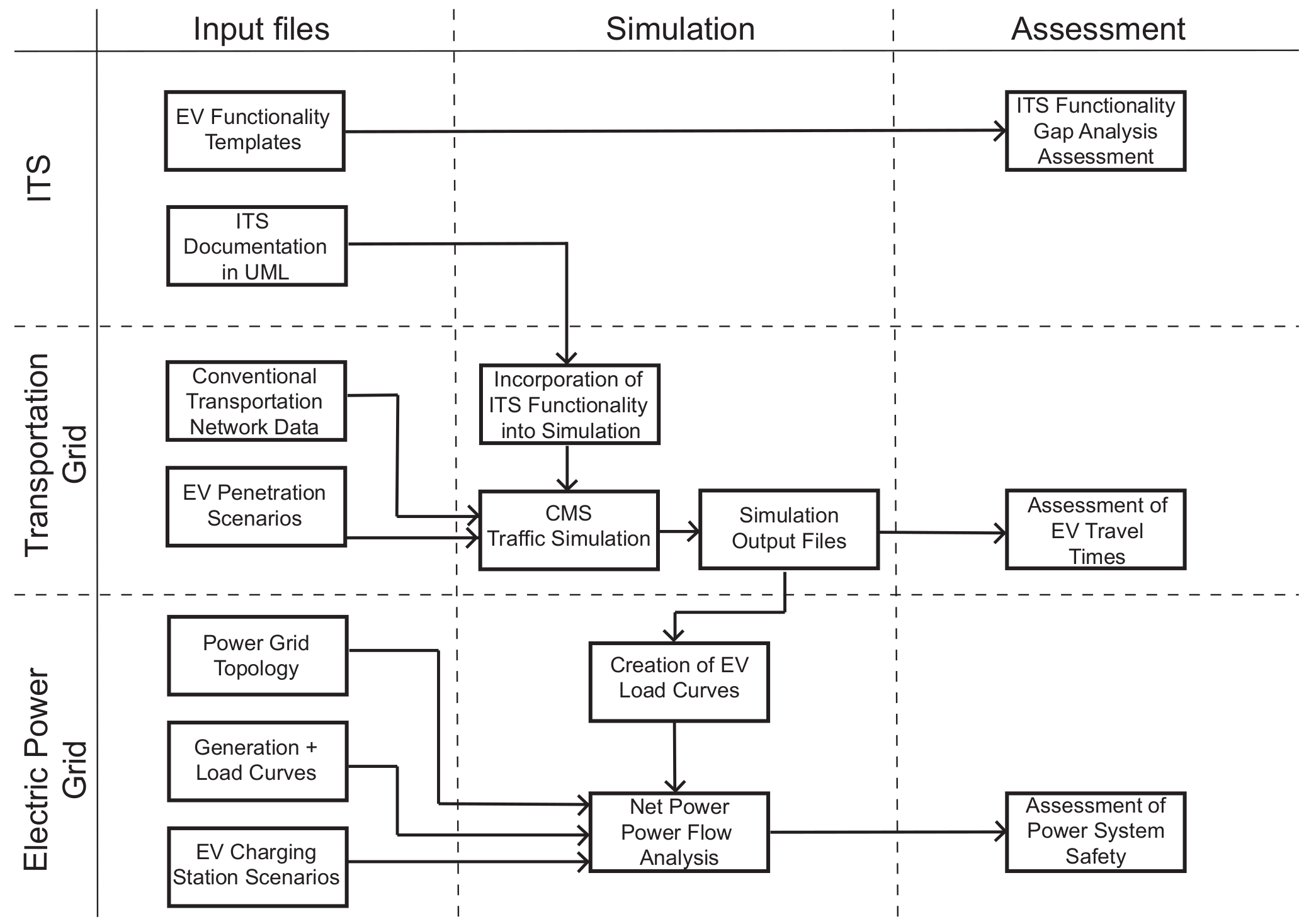
2.2. Assessment Method

Given the assessment requirements and performance measures of the previous section, the discussion can shift to the discussion of the methodology by which the electric vehicle integration study was carried out. In that regard, the previously published methodological developments [1,2,3,16,17,18,19,20,21,22] were revised so as to accommodate the availability of data and the usage of the Mitsubishi heavy industries clean mobility simulator. This section highlights some of the essential elements of that methodology and describes the unique aspects of the research methodology found within this study.
Figure 2 provides a schematic of the assessment method as a whole [1,2,3]. The EVs interact with three interconnected ‘systems-of-systems’: the (physical) transportation system, the electric power grid, and the ITS. For the traffic system, a microscopic discrete-time traffic operations simulator is used to study the kinematic state of the EV fleet at all times. For the electric power system, an analysis of power flows is used to determine the electrical charging loads required by the EV traffic usage patterns. Finally, an ITS functionality gap analysis is completed in relation to an EV functionality template.

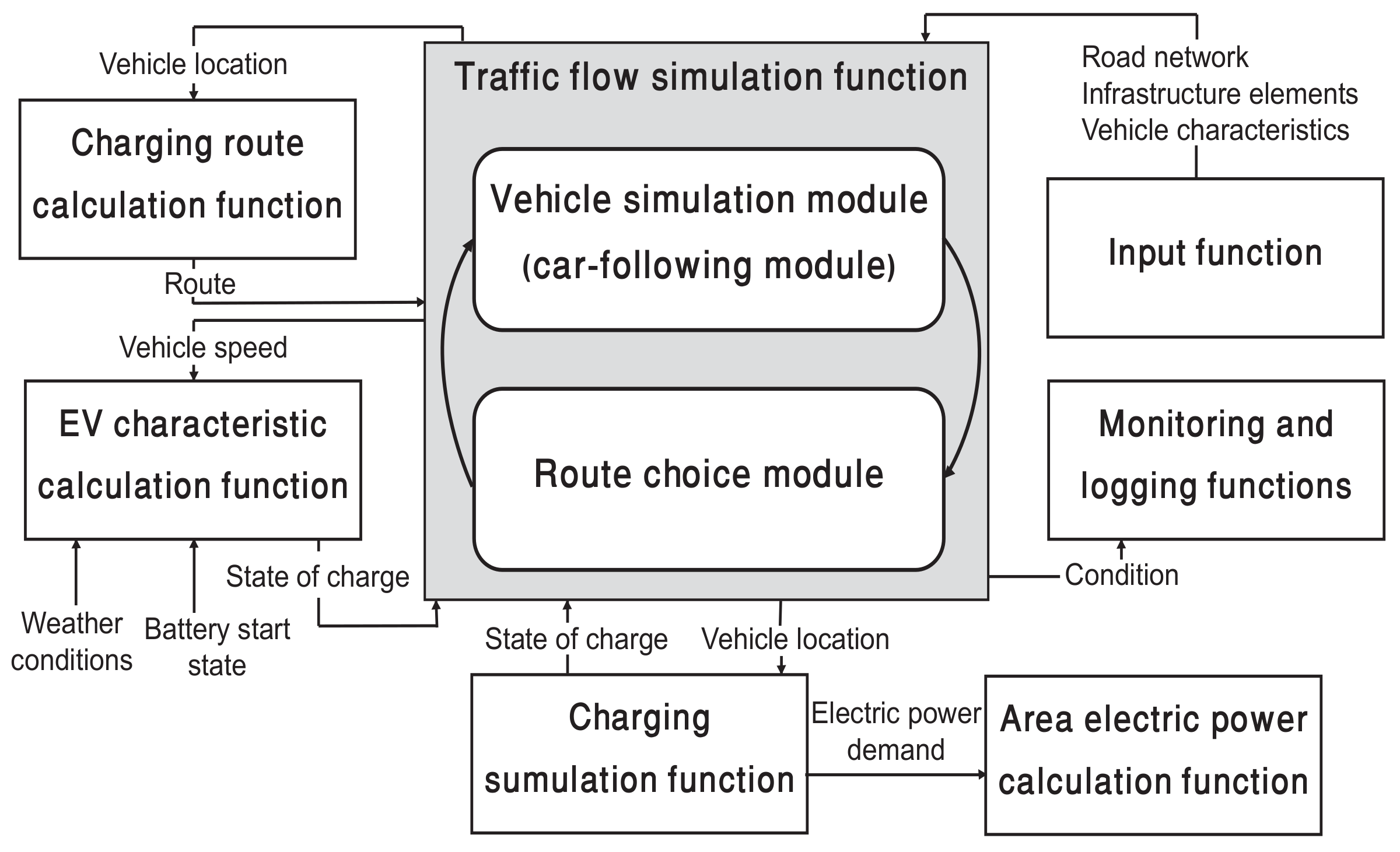
2.3. Clean Mobility Traffic Simulator

Although, in theory, any traffic simulator that meets the requirements described in Section 2.1.1 is sufficient, this work applies the “Clean-Mobility Simulator” (CMS) [34] because it embodies all the required functionalities of an EV simulator. As a discrete-time simulator, it gives a record of each EV’s kinematic state and state of charge with respect to time. As a result, the CMS is a tool that has potential to help understand whether EVs, with their technical limitations, meet the needs of transportation behavior in Abu Dhabi. As EV’s vehicular energy characteristics are quite important to their overall charging behavior [27], the CMS also has the ability to simulate traffic behavior while determining the energy demand and charging curves of individual EVs. More specifically, the i-MiEV was assumed as an electric vehicle model throughout the work. A schematic design of the CMS behavior is shown in Figure 3.

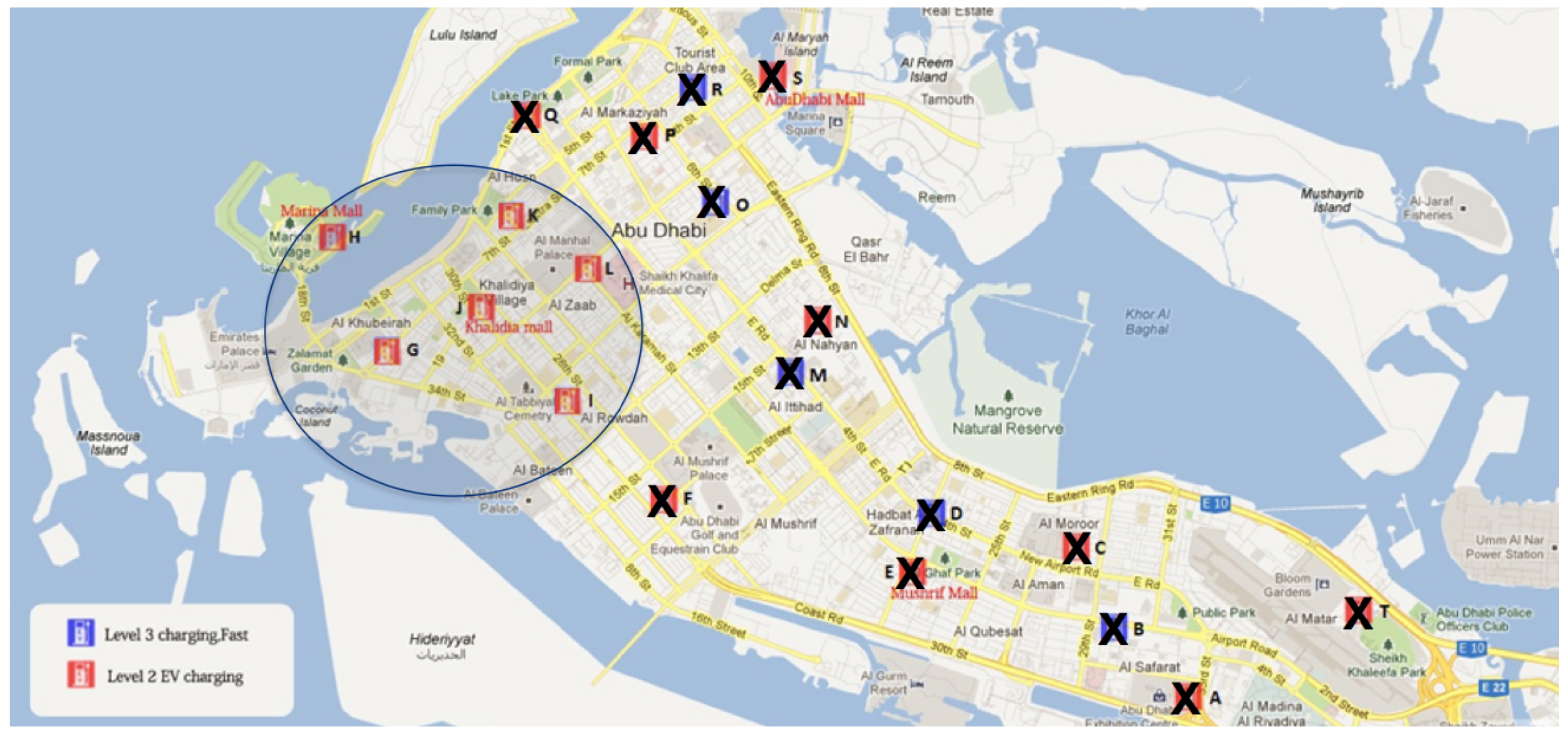
2.4. Abu Dhabi Base Traffic Simulation Setup

Once, the CMS was chosen as the traffic behavior simulator a number of steps were taken to develop a detailed and well-calibrated traffic behavior simulation base case of Abu Dhabi Island [2,3]. Figure 4 demonstrates the process of development. First, Abu Dhabi island was chosen as the geographical scope of the traffic simulation as it is the most densely populated geographical location in Abu Dhabi emirate. Abu Dhabi island, also has the highest likelihood of EV adoption. Thirdly, the data for the CMS simulator was gathered from different sources which include: traffic counts provided by the Abu Dhabi Department of Transportation (ADDOT), GPS loggers, and simulation parameters from the ADDOT simulator called STEAM. Next, the road transport network was determined and the CMS input file was generated. Finally, to complete the Abu Dhabi base case, the model was validated and calibrated by being compared to the STEAM model results.
It is important to recognize that the clean mobility simulator, like other traffic simulation tools, simulates traffic evolution from origin to destination and so does not capture any activity including charging before an origin or after a destination [34]. In order to overcome this challenge, the simulations were implemented as two sets of electric vehicles. The first set leaves in the morning with a full charge while the second set leaves in the afternoon with a 50% initial state of charge. No vehicle to grid charging was included in the simulation scenarios. As a result, the simulations assume that the vehicles that had travelled in the morning had done so and expended 50% of their charge in the process without drawing on the grid for power. Throughout all the simulations, the electric vehicles would automatically seek charging station once they reached a 20% state of charge. Note that because the simulation reflects a taxi or ride-share use case, one can not assume the presence of onsite or at-home charging. This charging rule represents an intentional desire to study the behavior of EVs “naively-integrated” without sophisticated coordination of vehicle dispatch, route choice, charging queues, charging dispatching, and vehicle-2-grid stabilization. In such a way, it gives a baseline sense of the potential effects of EV integration without such advanced control functions.

2.5. EV Penetration Use Case

Once the Abu Dhabi traffic simulation base case had been developed, attention shifted to choosing an EV penetration use case. A socio-economic study conducted in parallel to this work found that EVs greatest potential for adoption in Abu Dhabi existed in commercial use cases (e.g., government fleets of police and taxi cars) [32]. Upon further consideration, the taxi use case was deemed most suitable for further study because taxi traffic patterns most closely resembled the base case traffic patterns. In such a way, a certain percentage of base case ICV traffic (and their associated origin-destination pairs) could be readily replaced with EV taxi traffic.

2.6. Simulation Experimental Design

On this basis, a full experimental design composed of 12 hypothetical EV taxi integration scenarios was developed for the case study. It consisted of three values of EV penetration: 3%, 5%, and 10% of the base traffic simulation origin-destination pairs. Type II and Type III charging stations were chosen for the charging system design with charging rates of 19 kW and 50 kW per electric vehicle. The four charging system designs were called “Limited Dense”, “Limited Dense Mixed”, “Limited Sparse”, and “Full”. Figure 5, Figure 6, Figure 7 and Figure 8 show the type and geographic placement of the chargers for each configuration. The first two of these configurations are meant to emulate a limited roll out of EVs in one area of the Abu Dhabi island and differ in that the latter makes use of the faster Type III chargers. The limited sparse design introduces more Type II charging stations and spreads them out relatively sparsely such that there is one at every mall and park on the island. Finally, the full charging system adds a fast Type III charged at every gas station on the island. Given the relatively large penetration values and the commercial use case, each charging station was given a capacity of 50 vehicles. Similarly, each charging station was assumed to connect to a 1500 kW distribution substation—the size typically found in Abu Dhabi island for commercial applications. The safety criterion calculations were made on the assumption that this 1500 kW capacity rating was 16.7%, 33.3%, and 66.7% free.

3. Results

With the assessment methodology in place, the discussion proceeds to present the results of the integrated assessment. The transportation, power, and intelligent transportation systems are taken in turn.

3.1. Transportation System Assessment

The results of the transportation system assessment are summarized in Figure 9. In general, the limited roll out cases showed that the QoS had a relatively high susceptibility to increases in the EV penetration. Both the limited dense and limited dense mixed charging system design had significantly lower QoS at 10% than at 3% penetration. In contrast, the limited sparse and full cases which spread the charging stations across the city were much more able to accommodate increases in the EV penetration. The QoS values stayed relatively stable for EV penetrations between 3% and 10%.
As shown in Figure 10, the underlying reason for these QoS results is longer charging queues. With a fixed set of charging stations and increasing number of EVs, the waiting time of each vehicle to charge increases. Figure 10a,b show this effect for the limited dense case with an increase in penetration from 3% to 5%. In the 3% case, the charging station with the longest queue stays around 10 vehicles. In contrast, the 5% case had a longest queue that grew to almost 30 vehicles. Figure 10c shows a 5% scenario for the “Full Charging System Design”. It had, on average, longer queue lengths; presumably due to the spatial distribution of origin–destination pairs and their need for charging as a service. Although these numbers are large in an absolute sense, when interpreted in relation to the 50 vehicle charging station capacity, they are relatively modest. Even so, these figures shows that in order to maintain a high QoS, it is essential to increase the number of charging stations as the penetration of electric vehicles increases. Interestingly, the queue length plot for the 5% full case showed an even higher maximum queue length. This suggests that while in aggregate having an evenly spaced charging station fleet helps stabilize the QoS measure, it does not necessarily guarantee that specific charging stations will not experience long queue lengths.
Returning to Figure 9, it is worth noting that the addition of Type III chargers had a relatively small impact on QoS. In all, the results seem to suggest that QoS can be best maintained by first the charging station placement, second its capacity, and then lastly the type of charging station.
The simulations have demonstrated that the integration of electric vehicles in to the transportation system can have a significant detrimental impact on the quality of service provided by the electric vehicles. The implications of this are great depending upon the EV use case. Left unmitigated in public sector or commercial applications, such a degradation of quality of service can result in either direct or indirect loss of revenue. For example, EV taxi or EV bus passengers may decide to use other modes of transport as they experience delays in their travel itineraries. Government commercial fleets may find that the use of EV results in an impaired ability to execute their daily tasks. Such impacts can ultimately have negative word-of-mouth knock-on effect in the adoption rate of private users. Therefore, the ultimate viability of electric vehicles depends on technical efforts to mitigate the actual and perceived degradations in quality of service. One can frame the cost of these technical efforts within an ROI decision framework given an understanding between the relationship of quality of service and lost revenue [35].
The technical efforts to mitigate the degradation of quality of service ultimately requires that charging stations are geographically spread out across the city or the area of service. This is equally true for relatively small EV penetration rates. Technically speaking, a large number of charging stations geographically spread throughout the city may lead to acceptable quality of service in such circumstances. However, the aggregate value of charging stations per EV would be relatively high and potentially cost prohibitive on the supply side. EV users, coming from the conventional mentality of ICV transport, probably have a limited willingness to subsidize charging station infrastructure despite potentially demanding QoS requirements. An alternate solution would be to target use cases where the EV routes are well known and quantified. In such cases, charging station placement can be concentrated along these routes. Regardless of whether the EV adoption scenario is geographically broad or limited, significant future research is required in optimal placement methods that maintain QoS at minimal cost [35,36,37,38,39]. Such work must be done in conjunction with nascent work on the coordinated charging of electric vehicles [40,41,42,43,44,45,46,47].

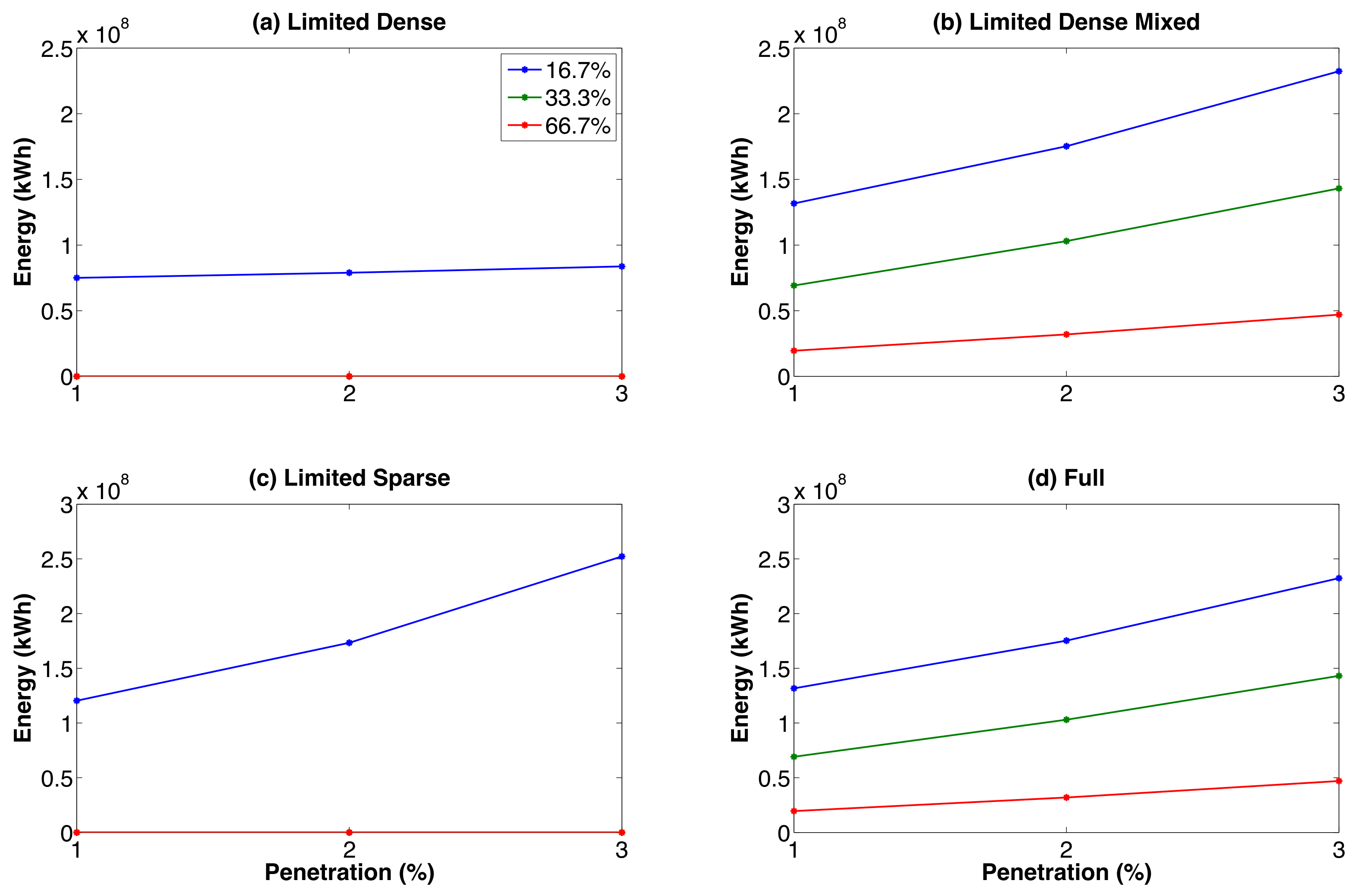
3.2. Power System Assessment

Depending on the driving pattern of Abu Dhabi’s drivers, the charging behavior will differ. This indicates that the electrical system plays an essential role in the wide adoption of EVs as it represents the main source of energy for charging. It is critical to determine the ability of the distribution network to handle the wide adoption of EVs into the transportation system. The supporting infrastructure is, therefore, essential to be modeled and assessed in the technical feasibility study of EVs in Abu Dhabi. The extent of EVs impact on the local power supply will depend on the degree and density of their penetration, charging requirements, as well as time of the day they are charged. Therefore, this assessment has considered these three aspects impacting the power system by addressing the 12 scenarios discussed in Section 2.1.1. The results are summarized by Figure 11 and Figure 12.
Before proceeding, it is important to note that the simulations showed that none of the morning trips expended sufficient battery to require morning charging. Subsequently, all charging occurred in the latter half of the day. As expected, in all cases, as EV penetration increases, so too does the total power demanded. The remainder of the section interprets and differentiates the results of the 12 simulation cases.

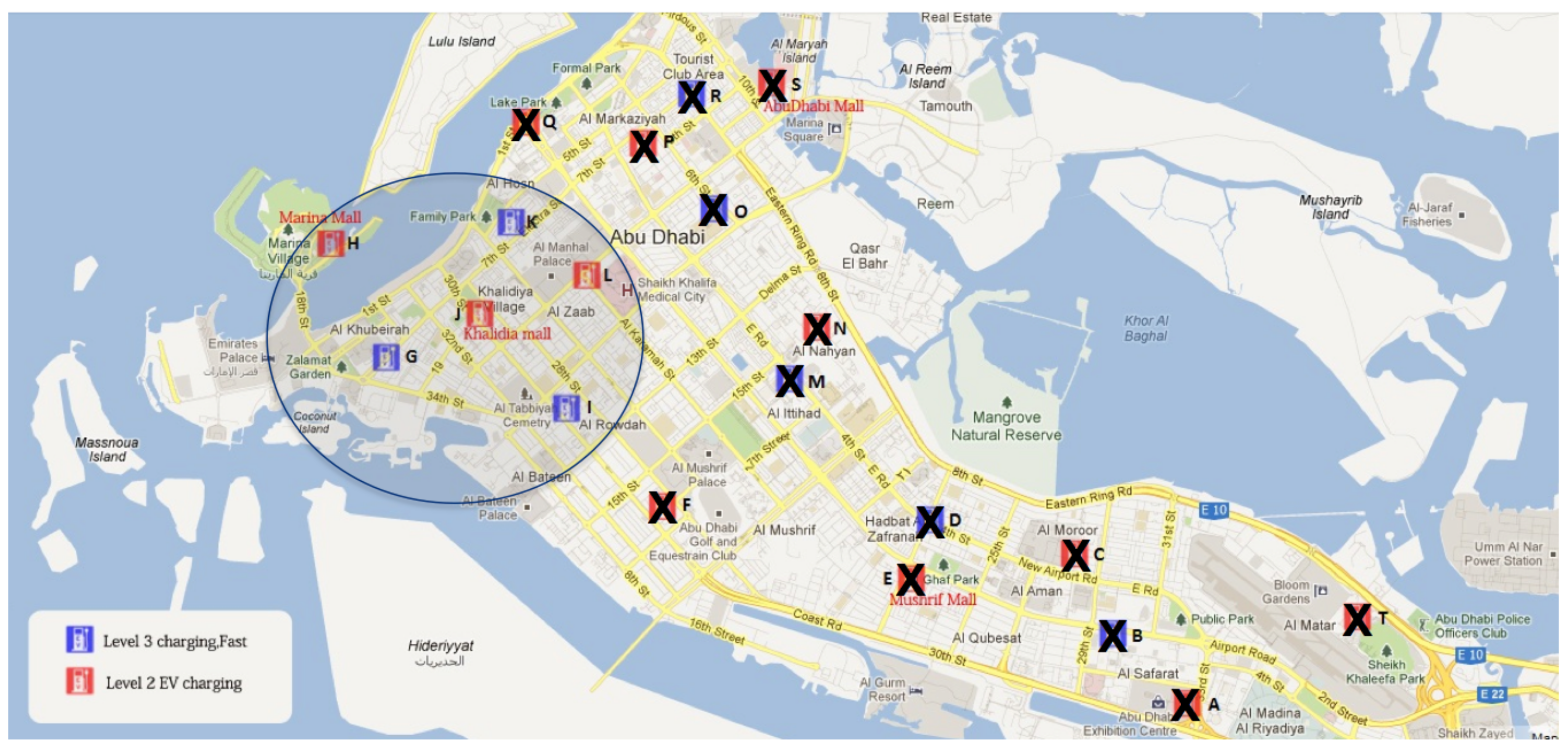
3.2.1. Limited Dense Charging System Design

The limited dense charging system design has the smallest charging system load curve at around 5 MW for all three penetration rates. In absolute terms, 5 MW comprises a very small portion of the Abu Dhabi generation capacity of 11 GWs [48]. Therefore, from an energy perspective at these modest penetration rates, EVs do not present a major challenge. More interestingly, this charging system’s load curve is characterized by saturation, which only becomes more prevalent with penetration rate. This saturation is due to the limitations in the number of chargers and their type and is best illustrated with a simple capacity calculation. Six charging stations each with 50 charging slots which consume at the Type II charger power of 19 kW yields 5.7 MW. Therefore, the charging station capacity becomes a type of system “bottleneck” where the impact on the power grid is the maximum possible but also generally decoupled from the vehicle dynamics in the transportation system. Although, this saturated and highly predictable load curve is desirable from a power utility perspective, it is entirely undesirable from a transportation system perspective in that it causes charging station queues and degraded quality of service. Recall from Section 3 that the limited dense charging station design resulted in low QoS values especially at higher penetration rates.
The corresponding line and transformer safety criterion values provide a similar understanding. As shown in Figure 12, the limited dense charging station design does not exceed transformer safety limits when 33.3% and 66.7% available capacity is assumed. Only in the case of 16.7% (i.e., 250 kW) of available power capacity does this charging station exceed the safety criterion; although it does so at the same level irrespective of penetration rate. Once again, the saturation of the charging station limits the power drawn to a highly predictable value.

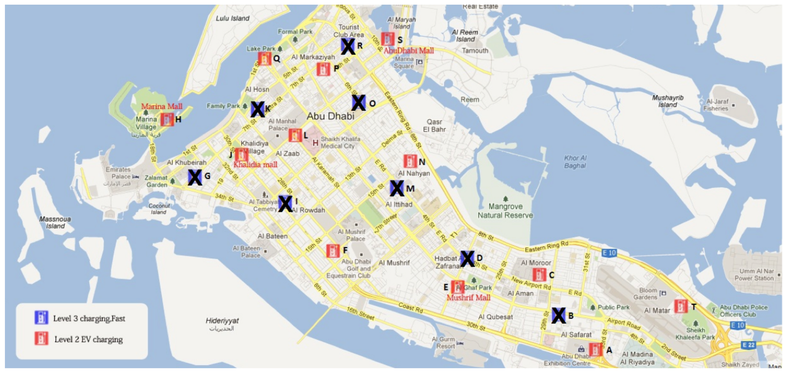
3.2.2. Limited Dense Mixed Charging System Design

The limited dense mixed charging station design has similar load curves to the limited dense case but with higher limits and greater variability. Although, the charging slots available are the same, the types of chargers differ. The Level III chargers are able to more quickly process any charging station queues and so the aggregate load curve is more variable than the limited dense charging station design. The replacement of three Level II chargers with Level III chargers also increased the saturated maximum power from 1 MW to 1.5 MW. As before, the saturation of chargers and the limiting maximum power gives an advantage to the power utilities because of the ease of predictability. However, as with the limited dense case, a degradation in the QoS follows.
The charging power variability in the limited dense mixed charging system provides a new operational challenge to power system utilities. Power utilities’ main operational challenge is to maintain the balance of power consumed and generated [49,50]. This task is easiest for well quantified, predictable, and slowly evolving loads. In contrast, the power drawn in this case is highly variable. Such a result suggests that power system utilities would have to use the power system’s regulation services to automatically control generation in response. Such a solution is technically viable provided that the degree of variability is within the saturation limits of the planned regulation service [49,50,51]. The variability on the order of 1MW is not likely to exceed any major technical limits. Nevertheless, regulation services are the most expensive form of power and their additional use can add an extra marginal cost for power utilities and their consumers [49].
As shown in Figure 12, the line safety criterion provides similar information for the limited dense mixed charging system design. In comparison to the limited dense charging system design, the inclusion of Type III chargers in the limited dense mixed charging system now requires lines and transformers to have greater available power capacity to avoid exceeding the safety limits regardless of whether there was 16.7%, 33.3%, or 66.7% of available power capacity. As shown in Figure 11, the total energy exceeding the power limit has a positive slope with the EV penetration rate. This suggests that the EVs are not just consuming more power but they are also doing so at times when other vehicles are charging; adding to the times in which the lines are over their safety limits.
The implications of such results are significant. Installation of such a charging station design would naturally require careful thought as they are integrated into the power grid. One solution would be to upgrade the lines and transformers to which the charging station is connected and another would be to connect the charging station to a higher distribution system voltage [15,26,52,53]. This would require a dedicated charging station transformer. Both solutions require significant capital expenditure, which may affect the ultimate viability of the envisioned EV adoption scenario.

3.2.3. Limited Sparse Charging System Design

Continuing to a more widespread charging station design, the limited sparse design shows an interesting interplay between the power drawn, the geographical sparsity and the variability. At 3% penetration, the power drawn varies between 5 and 10 MW with some variability but no saturation. Relative to the previous charging system designs, the addition of charging stations and their geographical distribution has allowed EVs to charge as is necessary with significantly reduced wait times. However, the relatively unconstrained charging has led to greater amplitudes in the charging power variability. Interestingly, this increase in charging power variability is not significantly greater than the previous charging station design due to the complete reliance on Type II charging stations. At 10%, the number of EVs begins to push the capacity limits of the limited sparse charging system design. The charging power evolves from 5–10 MW to a more consistent 13 MW. The power variability experienced at the lower penetration levels is replaced with near saturation as charging vehicles are quickly replaced from the oncoming traffic.
Despite the aggregate growth in the maximum charging power for this charging station design, a similar evolution in the safety criteria did not occur. At all penetration levels, the safety limits were not exceeded assuming 33.3% and 66.7% of available line capacity. It is only when the available line was limited to 16.7% that the safety criterion was exceeded. In this regard, the limited sparse charging system design resembled the behavior of the limited dense design because of its exclusive use of Type II chargers. In this case, however, the slope of the blue line is sharply upward while in the limited dense design it was nearly flat. This is because, in the limited dense case the charging stations are at or near capacity and the power drawn from the grid is consequently limited artificially. In contrast, the limit sparse case has the number and geographical distribution of charging stations that allow the value of the safety criterion to be not only larger but also grow to accommodate the increasing demand for EV charging. These results suggest that instead of upgrading line and transformer capacities, the impact on lines and transformers can be most reliably mitigated in the planning phase by ensuring that the lines and transformers have enough available capacity at all times to accommodate the maximum charging station power. Alternatively, a more complex yet cost-effective technical solution would be to implement an automated coordinated charging strategy which actively limits the charging station power to the currently available line and transformer power capacity [11,35,41].

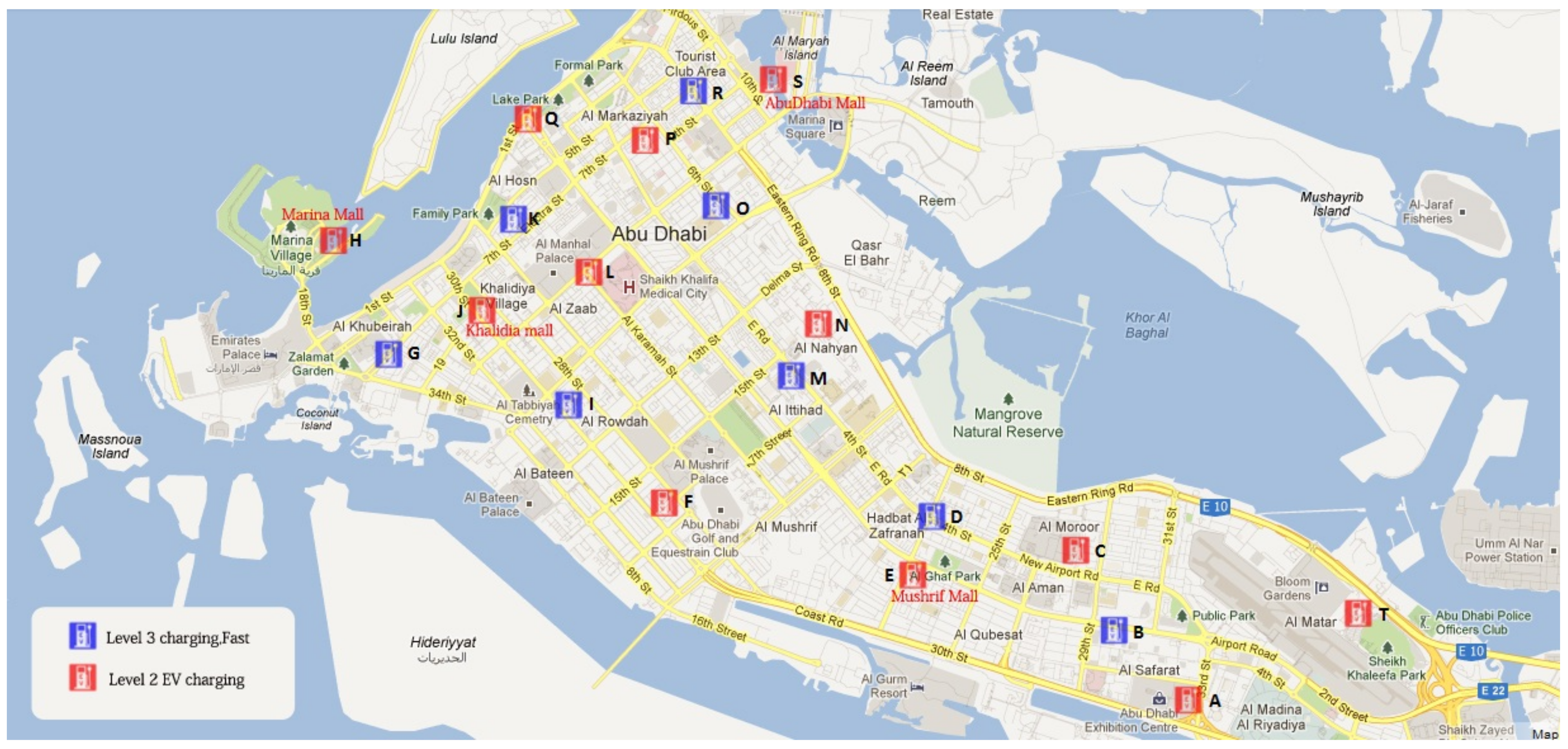
3.2.4. Full Charging System Design

The full charging system design presents the most aggravated impact on the power grid in regard to both the maximum charging power and the charging power variability. In this case, the charging system has sufficient capacity to bring its power impact onto the grid. Depending on the EV penetration rate, this maximum power could range from 7 to 20 MW. Although these values are not large in relation to the total generation capacity, in absolute terms they are equivalent to a significant size natural gas plant. Additionally, given that the charging system has sufficient capacity, the number of simultaneously charging EVs and the associated charging power can vary substantially. Relative to the limited sparse charging system, the effect is exacerbated by the presence of the Type III chargers.
As the charging system grows the EV penetration rate, the integration of EVs tends to appear more and more like a variable demand side energy resource. Its mitigation on the power system requires similar measures. Regulation services can do their part to eliminate some of the variability, but ultimately this solution is the costliest in terms of marginal price and is limited within market and regulatory limits [26]. Some of the variability must be mitigated in the power system dispatching. Such a solution requires that high fidelity charging system power forecasts be developed with good accuracy [26]. Research in this space can evolve along a number of directions.
In the case that limited information can be passed between the transportation and power systems, forecasting methods can be developed on the basis of statistical data mining methods [54]. In more transparent and cooperating circumstances, traffic simulation technology integrated within intelligent transportation systems can be used to deliver reliable forecasts [55]. Finally, coordinated charging techniques can be combined with a demand side response framework to actively manage the grid to the impact [41]. Ultimately, these challenges suggest a future convergence and collision of the intelligent transportation systems and smart grid disciplines and represent open directions for future research.
The full charging station design also presents a challenge to line and transformer power limits. As shown, the total power exceeding all three critical lines is the highest of all the scenarios. The mixture of charger types resulted in power exceeding the available capacities of 16.7%, 33.3%, and 66.7%. As with the limited dense mixed charging system, the full charging system design has a mixture of Level II and Level III chargers. A Level III charger has 50 charging slots each drawing 50 kW for a total of 2.5 MW. As the penetration increases, the likelihood of having all 50 vehicles plugged in at the same time increases; resulting in a positive slope with penetration rate. In such aggravated conditions, upgrading line and transformer limits are likely the only technical solution and would require the associated capital expenditures.

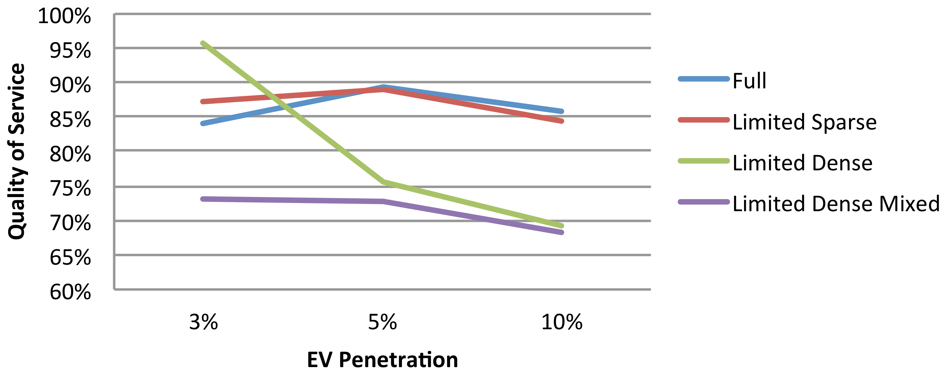
3.2.5. Summary of Power System Assessment

In all, the four charging system designs at the three penetration levels of 3%, 5%, and 10% clearly showed that the EV brings about an interesting interplay between the transportation system and the power system. In this transportation-energy nexus, insufficient charging station capacity limits the impact on the power grid but causes reduced electric vehicle quality of service. In the meantime, more charging stations that are more optimally placed can help alleviate degraded QoS values. In general, the often held solution of fast Type III chargers shifts the QoS problem back to the power grid aggravating line limits and causing grid variability. Ultimately, the large scale penetration of electric vehicles motivates a complex planning and operations of the transportation-energy nexus as a whole.

4. Discussion: The Need for an Intelligent Transportation-Energy System

The AD DOT ITS [56] is a conceptual vision of a final implementation rather than a detailed fixed current design. Therefore, at such an early conceptual design stage in the systems engineering process, the document rightly does not contain the detailed component interfaces or functional interactions. A complete reverse engineering analysis of the AD DOT ITS only lead to a very partial MDM. This means that the ITS design is still fluid enough that these detailed interfaces and interactions have not yet calcified thus facilitating incorporation of functionality and its associated modules and components.
The integrated assessment results from the previous section suggest that traffic and charging functionality must be considered holistically within an integrated operations management environment. Consider the concrete example of an EV taxi or bus operators. It may wish to dispatch its EVs along certain routes at certain times. However, this decision may depend on the existing charging station queues in the city. These queues in turn depend on the presence or absence of coordinated charging functions which may limit charging loads to the electrical grid. Finally, the local electric utility may even incentivize this EV operator to implement a “vehicle-to-grid” scheme to stabilize variability in grid conditions. Therefore, rather than an intelligent transportation system, it seems that electric vehicles require an intelligent transportation-energy systems (ITES) in recognition of the dual coordination role. For the remainder of this discussion, an ITES is taken to be a system with the combined functionality of an ITS and an energy/distribution management system. The nature of such a system is now discussed from the perspective of functional requirements, stakeholders and finally components.

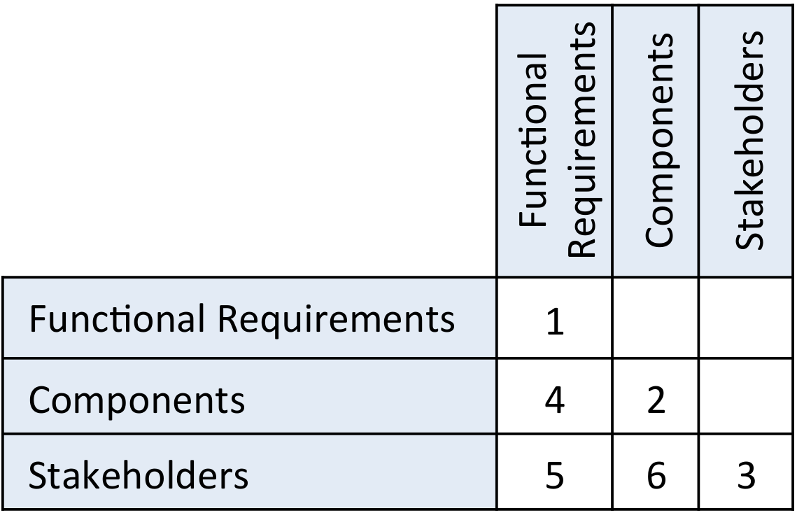
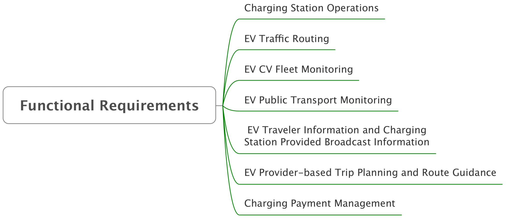
4.1. Integration of Functional Requirements

The integration of EVs adds new functionalities that are distributed across the potential program packages of a new ITES. Although the AD DOT ITS strategic vision highlights the importance of a low carbon economy as one of its top-level goals, energy management did not explicitly appear within the set of functional requirements. In contrast, Figure 13 proposes a new set of functional requirements (FR) to be part of the ITS which will help facilitate the management of EVs. These functional requirements include the management and operation of charging stations, as well as EVs.

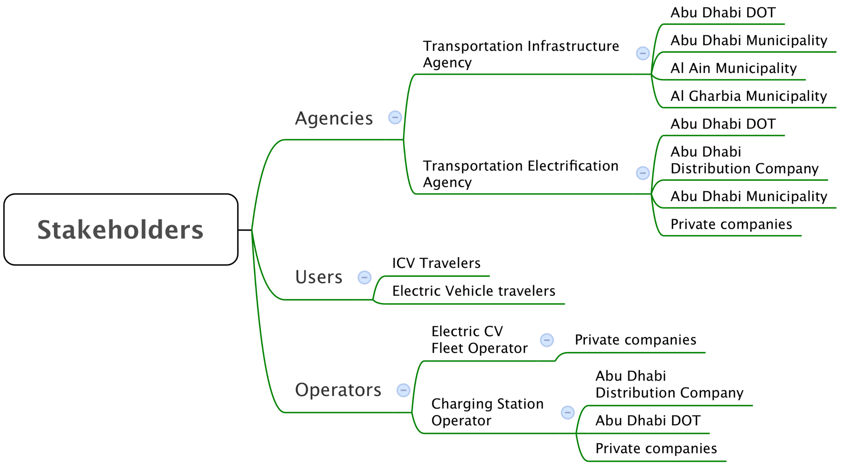
4.2. Integration of Stakeholders

The newly proposed ITES also adds new stakeholders into the system. These include charging station operators and electric vehicle drivers. Figure 14 demonstrates the additional roles and responsibilities of this enhanced group of stakeholders. Most interestingly, as EVs begin to couple the transportation and the power system, there will be additional responsibilities on electric utilities such as the Abu Dhabi Distribution Company (ADDC). Naturally, coordinated real-time operations management between the ADDOT and ADDC would present an interesting challenge of jurisdiction and cooperation.

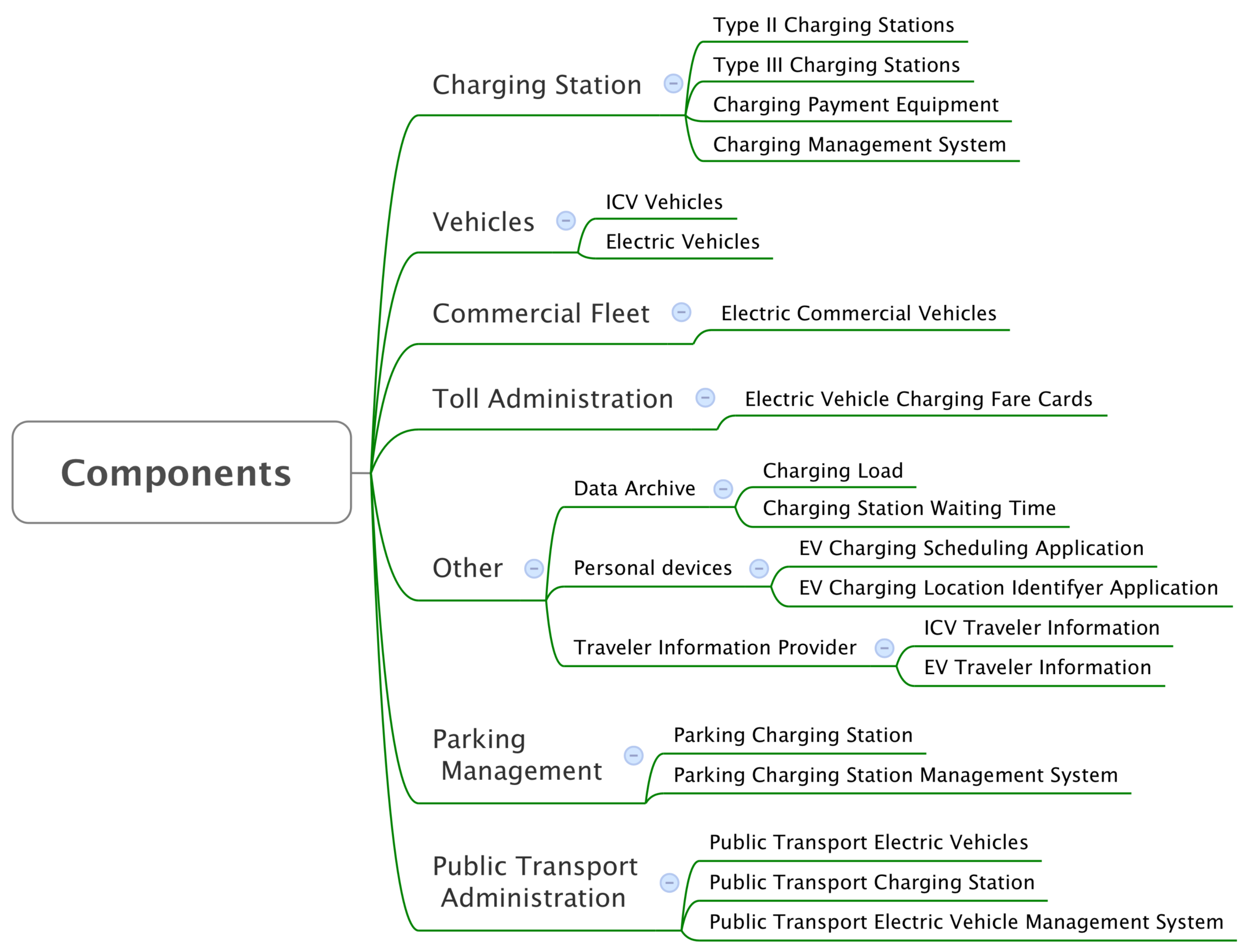
4.3. Integration of Components

The ITES would also call for a new set of management systems and technology elements to facilitate the adoption of EVs. Given that EVs have a number of potential use cases including: corporate fleets, public transportation, and private users, Figure 15 demonstrates the new components which may require potential integration. For example, charging stations can be available in taxi stands or parks. Each of these charging stations can be used for public transport or private users. Additionally, if a corporate vehicle fleet were to decide to switch to electric transportation, an EV management system will be required to do so. Another major change in the inventory list proposed is the classification of ICV and EV drivers. Each of these drivers will require a different set of services and therefore should be classified according to the vehicle type.

5. Conclusions

This paper has presented the first full scale technical feasibility assessment of electric vehicles for the city of Abu Dhabi. The assessment has provided a thorough assessment of 12 EV penetration scenarios based upon three penetration rates and four charging system designs. It showed clearly that the EV brings about a transportation-energy nexus in which negative impacts can be shifted from the transportation system to the power system and vice versa. Undesirable charging queues provide stable electric power loads to a utility while uncoordinated charging can cause electric vehicles to behave like variable energy resources. The mitigation of these averse impacts could have significant economic impacts outside the scope of the EV manufacturer that can ultimately impair the EV adoption trajectory.
The conclusions of the assessments results are summarized by Figure 16. The assessment results show that the design of the charging system itself is highly influential in either amplifying or mitigating the impacts of the EV integration. This is a multi-variable design space and unrationalized decisions can have unintended consequences on the combined transportation-energy nexus. The technical implications on the power system and transportation system for the five previously mentioned statistics. On the transportation side, low QoS which is also evidenced by low power variability and high maximum energy of load curves, can significantly impair long term EV adoption and reduce the revenue of the transportation services that choose to use electric vehicles. On the power system side, high max power could cause significant capital expenditures in upgrading lines and transformers. Meanwhile, high power variability will require the use of generation with significant ramping capabilities: flexible generation, synchronized reserves, and automatically controlled regulation services. All of these lead to a system wide increase in the marginal price of electricity. If there is insufficient flexibility in the generation fleet, then EV integration could potentially require further capital expenditures.

Author Contributions

The contributions of the authors are as follows: A.M.F. conceptualization, methodology, validation, writing—review and editing; A.V. software, data analysis, validation, writing—original draft preparation; R.A.-J. software, data analysis, validation, writing—original draft preparation; D.A. software, data analysis, validation, writing—original draft preparation; T.J.T.V.d.W. software, data analysis; All authors have read and agreed to the published version of the manuscript.

Funding

The authors would like to thank METI for its financial support of this research, Mitsubishi Heavy Industries for the use of its clean mobility simulator software and the Abu Dhabi Department of Transport for providing data on its traffic patterns and ITS.

Institutional Review Board Statement

Not Applicable.

Informed Consent Statement

Not Applicable.

Data Availability Statement

This study does not report any open data.

Conflicts of Interest

The authors declare no conflict of interest. The funders had no role in the design of the study; in the collection, analyses, or interpretation of data; in the writing of the manuscript, or in the decision to publish the results.

References

  1. Junaibi, R.A.; Farid, A.M. A Method for the Technical Feasibility Assessment of Electrical Vehicle Penetration. In Proceedings of the 7th Annual IEEE Systems Conference, Orlando, FL, USA, 15–18 April 2013; pp. 1–6. [Google Scholar]
  2. Junaibi, R.A. Technical Feasibility Assessment of Electric Vehicles in Abu Dhabi. Master’s Thesis, Masdar Institute of Science and Technology, Abu Dhabi, United Arab Emirates, 2013. [Google Scholar]
  3. Al Junaibi, R.; Viswanath, A.; Farid, A.M. Technical Feasibility Assessment of Electric Vehicles: An Abu Dhabi Example. In Proceedings of the 2nd IEEE International Conference on Connected Vehicles and Expo, Las Vegas, NV, USA, 2–6 December 2013; pp. 1–8. [Google Scholar]
  4. Skippon, S.; Garwood, M. Responses to battery electric vehicles: UK consumer attitudes and attributions of symbolic meaning following direct experience to reduce psychological distance. Transp. Res. Part Transp. Environ. 2011, 16, 525–531. [Google Scholar] [CrossRef]
  5. Pointon, J. The Multi-Unit Dwelling Vehicle Charging Challenge. In Proceedings of the Electric Vehicles Virtual Summit 2012. The Smart Grid Observer, Virtual Online. 13 September 2012; Volume 69. [Google Scholar]
  6. Pieltain Fernandez, L.; Roman, T.G.S.; Cossent, R.; Domingo, C.M.; Fria, A.P. Assessment of the Impact of Plug-in Electric Vehicles on Distribution Networks. IEEE Trans. Power Syst. 2011, 26, 206–213. [Google Scholar] [CrossRef]
  7. Lopes, J.A.P.; Soares, F.J.; Almeida, P.M.R. Integration of Electric Vehicles in the Electric Power System. Proc. IEEE 2011, 99, 168–183. [Google Scholar] [CrossRef] [Green Version]
  8. Qian, K.; Zhou, C.; Allan, M.; Yuan, Y. Modeling of Load Demand Due to EV Battery Charging in Distribution Systems. IEEE Trans. Power Syst. 2011, 26, 802–810. [Google Scholar] [CrossRef]
  9. Clement-Nyns, K.; Haesen, E.; Driesen, J. The Impact of Charging Plug-In Hybrid Electric Vehicles on a Residential Distribution Grid. IEEE Trans. Power Syst. 2010, 25, 371–380. [Google Scholar] [CrossRef] [Green Version]
  10. Dyke, K.J.; Schofield, N.; Barnes, M. The Impact of Transport Electrification on Electrical Networks. IEEE Trans. Ind. Electron. 2010, 57, 3917–3926. [Google Scholar] [CrossRef]
  11. Galus, M.; Zima, M.; Andersson, G. On integration of plug-in hybrid electric vehicles into existing power system structures. Energy Policy 2010, 38, 6736–6745. [Google Scholar] [CrossRef]
  12. Perujo, A.; Ciuffo, B. The introduction of electric vehicles in the private fleet: Potential impact on the electric supply system and on the environment. A case study for the Province of Milan, Italy. Energy Policy 2010, 38, 4549–4561. [Google Scholar] [CrossRef]
  13. Soares, J.A.; Canizes, B.; Lobo, C.; Vale, Z.; Morais, H. Electric Vehicle Scenario Simulator Tool for Smart Grid Operators. Energies 2012, 5, 1881–1899. [Google Scholar] [CrossRef] [Green Version]
  14. Chowdhury, M.A.; Sadek, A.W. Fundamentals of Intelligent Transportation Systems Planning; Artech House: Boston, MA, USA, 2003; p. xvii. 190p. [Google Scholar]
  15. Su, W.; Eichi, H.; Zeng, W.; Chow, M.Y. A Survey on the Electrification of Transportation in a Smart Grid Environment. IEEE Trans. Ind. Inform. 2012, 8. [Google Scholar] [CrossRef]
  16. Viswanath, A.; Farid, A.M. A Hybrid Dynamic System Model for the Assessment of Transportation Electrification. In Proceedings of the American Control Conference 2014, Portland, OR, USA, 4–6 June 2014; pp. 1–7. [Google Scholar]
  17. Farid, A.M. Electrified Transportation System Performance: Conventional vs. Online Electric Vehicles. In The On-line Electric Vehicle: Wireless Electric Ground Transportation Systems; Suh, N.P., Cho, D.H., Eds.; Springer: Berlin/Heidelberg, Germany, 2017; Chapter 20; pp. 279–313. [Google Scholar]
  18. Farid, A.M. Symmetrica: Test Case for Transportation Electrification Research. Infrastruct. Complex. 2015, 2, 9. [Google Scholar] [CrossRef] [Green Version]
  19. Farid, A.M. A Hybrid Dynamic System Model for Multi-Modal Transportation Electrification. IEEE Trans. Control Syst. Technol. 2016, 25, 940–951. [Google Scholar] [CrossRef]
  20. Allan, D.F.; Mezher, T.; Farid, A.M. Enhanced Electric Vehicle Adoption Scenarios for Abu Dhabi Road Transportation. In Proceedings of the UAE Graduate Students Research Conference, Abu Dhabi, United Arab Emirates, 27 April 2016; pp. 1–2. [Google Scholar]
  21. Van der Wardt, T.J.; Farid, A.M. A Hybrid Dynamic System Assessment Methodology for Multi-Modal Transportation-Electrification. Energies 2017, 10, 653. [Google Scholar] [CrossRef] [Green Version]
  22. Allan, D.F.; Farid, A.M. A Benchmark Analysis of Open Source Transportation-Electrification Simulation Tools. In Proceedings of the 2015 IEEE Conference on Intelligent Transportation Systems, Gran Canaria, Spain, 15–18 September 2015; pp. 1–7. [Google Scholar]
  23. Treiber, M.; Kesting, A. Traffic Flow Dynamics: Data, Models and Simulation; Springer: Heidelberg, Germany; New York, NY, USA, 2013; p. xiii. 503p. [Google Scholar]
  24. Barcelo, J. Fundamentals of Traffic Simulation; Springer: New York, NY, USA, 2010; p. xvii. 440p. [Google Scholar]
  25. Alecsandru, C.D. A Stochastic Mesoscopic Cell-Transmission Model for Operational Analysis of Large-Scale Transportation Networks. Ph.D. Thesis, Louisiana State University, Baton Rouge, LA, USA, 2006. [Google Scholar]
  26. Kassakian, J.G.; Schmalensee, R.; Desgroseilliers, G.; Heidel, T.D.; Afridi, K.; Farid, A.M.; Grochow, J.M.; Hogan, W.W.; Jacoby, H.D.; Kirtley, J.L.; et al. The Future of the Electric Grid: An Interdisciplinary MIT Study; MIT Press: Cambridge, MA, USA, 2011; pp. 1–280. [Google Scholar]
  27. Doyle, A.; Muneer, T. Energy consumption and modelling of the climate control system in the electric vehicle. Energy Explor. Exploit. 2019, 37, 519–543. [Google Scholar] [CrossRef] [Green Version]
  28. González Palencia, J.C.; Nguyen, V.T.; Araki, M.; Shiga, S. The Role of Powertrain Electrification in Achieving Deep Decarbonization in Road Freight Transport. Energies 2020, 13, 2459. [Google Scholar] [CrossRef]
  29. Anonymous. Systems Engineering for Intelligent Transportation Systems: An Introduction for Transportation Professionals; Technical Report; U.S. Department of Transportation Federal Highway Administration Federal Transit Administration: Washington, DC, USA, 2007. [Google Scholar]
  30. Rumbaugh, J.; Jacobson, I.; Booch, G. The Unified Modeling Language Reference Manual; Addison-Wesley: Boston, MA, USA, 2005. [Google Scholar]
  31. Eppinger, S.D.; Browning, T.R. Design Structure Matrix Methods and Applications; MIT Press: Cambridge, MA, USA, 2012; p. xii. 334p. [Google Scholar]
  32. Hadhrami, M.A.; Viswanath, A.; Junaibi, R.A.; Farid, A.M.; Sgouridis, S. Evaluation of Electric Vehicle Adoption Potential in Abu Dhabi; Technical Report; Masdar Institute of Science and Technology: Abu Dhabi, United Arab Emirates, 2013. [Google Scholar]
  33. PJM; Department of Operations Support. PJM Manual 12: Balancing Operations; Technical Report; PJM: Norristown, PA, USA, 2011. [Google Scholar]
  34. Sonoda, T.; Kawaguchi, K.; Kamino, Y.; Koyanagi, Y.; Ogawa, H.; Ono, H. Environment-Conscious Urban Design Simulator “Clean Mobility Simulator”—Traffic Simulator that Includes Electric Vehicles. Mitsubishi Heavy Ind. Tech. Rev. 2012, 49, 78–83. [Google Scholar]
  35. Gan, L.; Topcu, U.; Low, S. Optimal decentralized protocol for electric vehicle charging. In Proceedings of the IEEE Conference on Decision and Control and European Control Conference, Orlando, FL, USA, 12–15 December 2011; pp. 5798–5804. [Google Scholar] [CrossRef] [Green Version]
  36. Wei, W.; Wu, L.; Wang, J.; Mei, S. Expansion planning of urban electrified transportation networks: A mixed-integer convex programming approach. IEEE Trans. Transp. Electrif. 2017, 3, 210–224. [Google Scholar] [CrossRef]
  37. Palomino, A.; Parvania, M. Advanced charging infrastructure for enabling electrified transportation. Electr. J. 2019, 32, 21–26. [Google Scholar] [CrossRef]
  38. Amini, M.H.; Mohammadi, J.; Kar, S. Distributed holistic framework for smart city infrastructures: Tale of interdependent electrified transportation network and power grid. IEEE Access 2019, 7, 157535–157554. [Google Scholar] [CrossRef]
  39. Amini, M.H. A panorama of interdependent power systems and electrified transportation networks. In Sustainable Interdependent Networks II; Springer: Berlin/Heidelberg, Germany, 2019; pp. 23–41. [Google Scholar]
  40. Ahman, M. Government policy and the development of electric vehicles in Japan. Energy Policy 2006, 34, 433–443. [Google Scholar] [CrossRef]
  41. Kempton, W.; Tomić, J. Vehicle-to-grid power implementation: From stabilizing the grid to supporting large-scale renewable energy. J. Power Sources 2005, 144, 280–294. [Google Scholar] [CrossRef]
  42. Lund, H.; Kempton, W. Integration of renewable energy into the transport and electricity sectors through V2G. Energy Policy 2008, 36, 3578–3587. [Google Scholar] [CrossRef]
  43. Amini, M.H.; Mohammadi, J.; Kar, S. Distributed intelligent algorithm for interdependent electrified transportation and power networks. In Proceedings of the 9th ACM Symposium on Design and Analysis of Intelligent Vehicular Networks and Applications, New York, NY, USA, 25–29 November 2019; pp. 73–79. [Google Scholar]
  44. Bartłomiejczyk, M. Potential application of solar energy systems for electrified urban transportation systems. Energies 2018, 11, 954. [Google Scholar] [CrossRef] [Green Version]
  45. Lv, S.; Wei, Z.; Sun, G.; Chen, S.; Zang, H. Optimal power and semi-dynamic traffic flow in urban electrified transportation networks. IEEE Trans. Smart Grid 2019, 11, 1854–1865. [Google Scholar] [CrossRef]
  46. Wei, W.; Mei, S.; Wu, L.; Shahidehpour, M.; Fang, Y. Optimal traffic-power flow in urban electrified transportation networks. IEEE Trans. Smart Grid 2016, 8, 84–95. [Google Scholar] [CrossRef]
  47. Amini, M.H.; Karabasoglu, O. Optimal operation of interdependent power systems and electrified transportation networks. Energies 2018, 11, 196. [Google Scholar] [CrossRef] [Green Version]
  48. Anonymous. The Abu Dhabi Economic Vision 2030; Technical Report; The Government of the Emirate of Abu Dhabi: Abu Dhabi, United Arab Emirates, 2008. [Google Scholar]
  49. Gomez Exposito, A.; Conejo, A.J.; Canizares, C. Electric Energy Systems: Analysis and Operation; The Electr; CRC: Boca Raton, FL, USA, 2008; Chapter 127–164. [Google Scholar]
  50. Schavemaker, P.; Van der Sluis, L.; Books24x7 Inc. Electrical Power System Essentials; Wiley: Chichester, UK; Hoboken, NJ, USA, 2008; p. xiii. 325p. [Google Scholar]
  51. Wood, A.J.; Wollenberg, B.F. Power Generation, Operation, and Control, 2nd ed.; J. Wiley & Sons: New York, NY, USA, 1996; Volume 2, pp. 1–593. [Google Scholar]
  52. Brown, S.; Pyke, D.; Steenhof, P. Electric vehicles: The role and importance of standards in an emerging market. Energy Policy 2010, 38, 3797–3806. [Google Scholar] [CrossRef]
  53. Li, Z.; Ouyang, M. The pricing of charging for electric vehicles in China—Dilemma and solution. Energy 2011, 36, 5765–5778. [Google Scholar] [CrossRef]
  54. Mak, S.T. Knowledge Based Architecture Serving As a Rigid Framework for Smart Grid Applications. In Proceedings of the Innovative Smart Grid Technologies (ISGT), Gaithersburg, MD, USA, 19–21 January 2010; p. 8. [Google Scholar]
  55. Gong, Q.; Li, Y.; Peng, Z.R. Optimal Power Management of Plug-in HEV with Intelligent Transportation System. In Proceedings of the 2007 IEEE/ASME International Conference on Advanced Intelligent Mechatronics, Zurich, Switzerland, 4–7 September 2007; pp. 1–6. [Google Scholar] [CrossRef]
  56. ADDOT-Anonymous. Abu Dhabi Intelligent Transportation Systems: Strategy Architecture and Implementation Action Plan 2010–2030; Technical Report 3; Abu Dhabi Department of Transportation: Abu Dhabi, United Arab Emirates, 2011. [Google Scholar]
Figure 1. Multi-domain matrix (MDM).
Smartcities 04 00055 g001
Figure 2. Methodology of assessment [1,2,3].
Smartcities 04 00055 g002
Figure 3. Schematic design of the CMS behavior [34].
Smartcities 04 00055 g003
Figure 4. Development Process of Abu Dhabi’s Base Traffic Simulation Case.
Smartcities 04 00055 g004
Figure 5. Limited Dense Charging System Design Map.
Smartcities 04 00055 g005
Figure 6. Limited Dense Mixed Charging System Design Map.
Smartcities 04 00055 g006
Figure 7. Limited Sparse Charging System Design Map.
Smartcities 04 00055 g007
Figure 8. Full Charging System Design Map.
Smartcities 04 00055 g008
Figure 9. Quality of service results.
Smartcities 04 00055 g009
Figure 10. Queue length in time in three indicative scenarios.
Smartcities 04 00055 g010
Figure 11. Charging system load curves for all 12 simulation cases.
Smartcities 04 00055 g011
Figure 12. Safety criterion results.
Smartcities 04 00055 g012
Figure 13. Integration of EVs as a functional requirement in Abu Dhabi’s ITES [2].
Smartcities 04 00055 g013
Figure 14. Integration of EVs as new stakeholders in Abu Dhabi’s ITES [2].
Smartcities 04 00055 g014
Figure 15. Integration of EVs as new components in Abu Dhabi’s ITES [2].
Smartcities 04 00055 g015
Figure 16. Charging System Design Heuristics for Mitigation of Impacts to Transportation-Energy Nexus [2].
Smartcities 04 00055 g016
Table 1. Intelligent transportation-energy system operations decisions in the transportation electricity nexus.
  • Vehicle dispatch: When a given EV should undertake a trip (from origin to destination)
  • Route choice: Which set of roads and intersections it should take along the way
  • Charging station queue management: When and where it should charge in light of real-time development of queues
  • Coordinated charging: At a given charging station, when the EVs should charge to meet customer departure times and power grid constraints
  • Vehicle-2-grid stabilization: Given the dynamics of the power grid, how can the EVs be used as energy storage for stabilization
Publisher’s Note: MDPI stays neutral with regard to jurisdictional claims in published maps and institutional affiliations.

