Concept Paper

Development of User-Integrated Semi-Autonomous Lawn Mowing Systems: A Systems Engineering Perspective and Proposed Architecture

Department of Industrial and Enterprise Systems Engineering, University of Illinois at Urbana-Champaign, 117 Transportation Building, 104 South Mathews Avenue, Urbana, IL 61801, USA
*
Author to whom correspondence should be addressed.
Submission received: 25 July 2019 / Revised: 23 August 2019 / Accepted: 6 September 2019 / Published: 11 September 2019

Abstract

:
This concept paper outlines a conceptual framework for the design and development of user-integrated semi-autonomous lawn mowing systems. This is approached from a systems engineering perspective, considering both hardware and software elements and integration with the user. This is an important and emerging field of study within the several engineering communities, including robotics, agricultural engineering, smart city development, and general systems engineering. In several sections of this paper, a review of current progress on this problem is presented (both in general and related to specific aspects of the system), followed by a discussion of the problem from a systems engineering perspective, a general system architecture developed by the authors, a preliminary set of design requirements, and a discussion of some practical implementation strategies. This work is meant to provide a baseline and motivation for the further development and refinement of these systems within the agricultural engineering and robotics communities and is relevant to both academic and commercial research.

1. Introduction and Background

1.1. Motivation and Problem Overview

Lawn mowing is one of the most essential tasks required for most home owners, requiring a significant investment of time and resources to accomplish properly. In 2018, lawn mowing equipment was estimated to be a US $27.5 billion global industry and projected to continue growing a further 5.2% between 2019 and 2025 [1]. In addition to the significant investment in equipment and time for the users, it is also typically considered to be an unpleasant task to complete and one that users would like to avoid when possible. In recent years, this has given rise to attempts to make lawn mowers more robotic and more autonomous, resembling the now-widespread Roomba vacuum cleaners [2,3,4]. There are a number of technical and system-level challenges with doing this for lawn mowers, however; this is a much more complex problem than the development of a robotic vacuum cleaner for four major reasons, namely, (1) the boundary and environmental conditions during use are much less well-defined, (2) a lawn mower has the potential to cause significant damage and injury to humans and animals if is goes rogue, (3) it is a much larger system with more complex set of sensors and controls, and (4) it is a much more valuable and expensive system. In addition to driving complexity in the system, these reasons all necessitate a rigorous security system, including hardware and software security, and a remote kill switch. To support the mower system, an effective method for maintaining the system is needed, as well as a mapping method.
The application of autonomous and semi-autonomous robotic systems to lawn mowing and other human-assistant tasks [5,6] has been the topic of several major studies, mainly focused on how to accomplish effective path planning and how to control the system. Autonomous and semi-autonomous mowers should be clearly distinguished from simple automatic mowers [4,7], as the latter are not the topic of the present study. An autonomous system is defined as one that can act independently once a job is initiated by a human user; this may take the form of a human defining the parameters in which the machine may act and either scheduling operations or directly initiating jobs each time it is needed. At the current time, it is generally necessary for some kind of monitoring to be used in case the system loses control. In the case of a semi-autonomous system, there is a degree of autonomy in the system, but there is still a human interface with the system and the operator provides at least some of the control and direction of the system (the system may act autonomously some of the time). A logical understanding of the theoretical relationship between autonomous, semi-autonomous, and automated/tele-operated systems is shown in Figure 1. The most simple definitions of these are that automated systems follow a programmed set of operations and do not have any autonomous operation; tele-operated systems are similar, except that a human is directly controlling the system and can react to unexpected events accordingly. These definitions are given in order to ensure that the approach and architecture presents in this paper can be clearly understood and contextualized.

1.2. Previous Work: Mowing Systems

Toward the development of autonomous/semi-autonomous mowing systems, Shiu & Lin [8] considered several different modes for optimal path planning, including minimal working time, minimal energy consumption, and mixed operation. The system required the use of GPS for localization and tracking of the job. Considerations for path planning and obstacle avoidance in area where GPS coverage is poor was explored in depth by Nourani-Vatani et al. [9]; localization was done using laser-based localization and a virtual force field algorithm near identified obstacles. There was some significant deviation noted from the planned paths during physical experiments, but the method did effectively avoid the obstacles. Focus only on the development of an effective autonomous/semi-autonomous mower controller was the topic of studies by Wasif et al. [10] and Daltorio et al. [11]. The controller developed by Wasif et al. used sonar to find the ranges to any identified obstacles, GPS to localize the mower in the global space, local positioning using odometry, and an on-board camera to track the mowed areas. Daltorio used a similar range of instruments, with the addition of LIDAR and a greater focus on GPS positioning.

1.3. Previous Work: Navigation, Data Processing, and Path Planning

Work on more specific topics relevant to semi-autonomous mowing systems, particularly in the areas of navigation and localization, data processing, and path planning, has been done in recent years. While most of these cases focused on different applications or more general cases, any functional decomposition diagram of a semi-autonomous mowing system (an example of which can be seen in Figure 2) shows that knowledge of these areas is vital. Previous research in areas such as the basic functions of a lawn mower, instrumentation, and health monitoring are well-developed general topics that will not be examined here. Navigation, data processing during operation, and path planning are given the attention, as these are areas where further development is needed. It is important to understand the status of these areas, as their level of maturity will affect the design and development of systems making use of them in operation. They can be considered to be the limiting technology for a semi-autonomous system.
Peless et al. [12] developed a local navigation system that utilized a proximity sensor on the robot itself which was able to interact with a defined boundary on the working area; the robot would begin at a known location and then continuously track its location relative to the boundary. Corrections during used were made by comparing the measured coordinated with those on a user-defined map. Generation of the map automatically using UAVs was explored by Samad et al. [13], while the use of ground robots for this purpose was proposed by Choi et al. [14]. In both studies, high-quality digital images were used to generate a map of terrain and potential obstacles, while the ground robot was supplemented with LIDAR to aid in the detection of important terrain features and partially hidden obstacles. These methods were found to be effective in locating grassy areas and obstacles but still missed some features such as grates and manhole covers. A practical configuration for mapping and avoiding obstacles was proposed by Franzius et al. [15], which used a single camera and simple processing board which could be added to existing robotic mowing systems. It was observed over extensive testing (nearly 3500 hours of testing) that the system developed did not need any direct human intervention to accomplish acceptable mowing performance, but some collisions with small obstacles did occur as the system was not able to locate and avoid all of them.
Processing of the images collected by the mapping strategies is another topic of research, as effective machine interpretation of the images and conversion into a map is vital to the working of an autonomous/semi-autonomous mowing system. Schepelmann et al. [16] proposed an image-segmentation method which extracts identifiers to locate grass-containing regions and then apply use the texture statistics for distinguishing grass and obstacles. This method is inexpensive and quick, but may be biased by unfavorable lighting conditions or blurry areas in the used images. This texture division method was further developed by Guo et al. [17], making the lighting and scaling factors of the images much less impactful through the use of a Gabor filter. Zhang et al. [18] proposed a method for estimating the biomass of grass within a specific area from images, helping to estimate its weight and density; this was done primarily for predicting fire control needs, but the method is applicable to mowing, as it can help calculate mowing time, power requirements, and other important characteristics during job planning. A method to detect trash within a grassy environment was proposed by Bai et al. [19], using a ground segmentation method and a deep neural network to detect the foreign items. Similarly, a field robotic system to detect a specific species of weeds, also using neural networks to examine 2-D images of the field, was developed by Kounalakis et al. [20].
Automated and intelligent path planning, as long as it can be shown to be reliable for the needed conditions, can help to find the best coverage for a particular yard or field. These methods may be used to adapt in real-time if the map needs to be updated after beginning the job (such as when the system encounters an unexpected obstacle). While a reliable and efficient method for accomplishing this does not seem to have been developed yet, there are several established solutions that work well in particular applications. The most popular approach to the problem uses a divide-and-conquer strategy [21] to achieve completeness easily by dividing a given area into several cells and covering each cell by a path that requires minimum time. Choset [21,22] introduced boustrophedon decomposition, where a line segment is swept through a given environment, forming a new cell when there is a change in the connectivity of the slice described by critical points. The robot then covers each of the cells using a simple zig-zag motion. Acar et al. [23] used Morse decomposition to use the critical points of Morse function to form the cells so that complete coverage of each cell is guaranteed. A cell decomposition algorithm based on topological structures was proposed by Wong & MacDonald [24], which is more simple and time-efficient than many other methods. To save time during operation and reduce the distance traveling by the robot, Yao [25] tried to ensure that the entry and exit points between each of the cells coincided or were at least as close as possible to each other.
Dynamic environment path planning was the focus of several studies by Elhoseny et al. [26], Darwish et al. [27], Ferrer & Sanfeliu [28], Liu et al. [29], Reinhart et al. [30], and Wei & Ren [31]. Elhoseny et al. were focused on optimal path planning in harsh environments, using a Bezier curve and genetic algorithm to generate smooth curves. The Bees algorithm used by Darwish et al. was able to find optimal paths in several different case studies and was shown to react to the presence of dynamic obstacles in a real dynamic environment; the Bees algorithm is a “continuous optimization” method [32] well-suited for this kind of problem. The path planning scheme proposed by Ferrer & Sanfeliu used anticipative kinodynamic planning (AKP) to plan the path, the objective being to minimize impact on the local environment by the robot. Instead of avoiding obstacles to protect the robot or accomplish the mission efficiently, the path was planned to protect the obstacles (typically humans, as stated in the study design). In contrast to the previous path planning schemes, the cleaning robot system designed by Lui et al. covers the entire space while avoiding the present obstacles instead of taking the shortest or least energy-intensive path. To accomplish this, a new algorithm named Complete Coverage Path Planning (CCPP) is proposed and demonstrated successfully. Finally, in the two cases from Reinhart et al. and Wei & Ren, the robots in question are not free-running vehicles, but arms which have a fixed linkage. The control schemes for these cases are more complex than for the vehicle-based robots, as the entire robot cannot simply move out of the way of the dynamic obstacles. The environment within the study by Wei & Ren is very structured, with several major assumptions made, unlike those of the other studies. While Wei & Ren focused on real-world experimental validation, the work by Reinhart et al. focused on using machine learning to gradually improve the performance of the system as more data is presented to the model. The hybrid modeling approach taken was noted to improve the basic modeling of the system, helping improve control and path planning.

1.4. Main Areas of Applicability

There are several areas where advancement of semi-autonomous mowing systems would prove beneficial, primarily in agricultural engineering. While the exact nature of the problem discussed here is more related to general robotic systems, home maintenance, and smart/IoT technologies, the impact of a good solution is wide. Field robotics are rapidly becoming more widespread in agricultural settings, as many random and difficult condition exist in these settings. Field robots, by definition, work in a space that must be monitored and reacted to by the vehicle as unexpected events are encountered. While the operational space for semi-autonomous mowing systems is more limited than a typical field robot (which may be tele-operated, semi-autonomous, or fully autonomous), many of the challenges are the same. For example,
  • It is not always possible to rely on GPS coverage with either a field robot or mowing system, making navigation systems such as dead reckoning, beacon finding, and drive-by-sight necessary in some cases. In a more urban outdoor environment, GPS coverage is likely much more reliable (due to built-in redundancies in highly populated areas [33]) and the layout of the space is more logical and easy for a map to be made of it for the robot. This is of course not always the case, but it can be generally assumed that city streets are more clearly laid out and planned than dirt paths in more rural areas and large areas of grass (in yards and similar).
  • For both agricultural and semi-autonomous mowing systems, the lack of buildings locally may make it more difficult to map the space. Buildings can be recognized by the on-board instruments and can be used as markers and space limits. For field robotics and mowing systems, there may be a single building (such as a house or barn) or nothing (such as on a golf course or field). This lack of building decreases the available easily-spotted landmarks and increases the possible distance between the system and operators. This can be mitigated somewhat by using UAVs as markers (or mappers), by using more long-range communication strategies, and similar strategies that would require more active setup from the user.
  • In urban environments, the encountered obstacles are both more likely to be static and standardized (cars, manhole covers, poles, traffic cones) or very unpredictable (cars, animals not afraid of machinery); both mowing system and other agricultural robotic systems are more likely to encounter generally unpredictable obstacles (e.g., animals and debris from storm damage) and obstacles which may block control and GPS signals in some areas (e.g., large trees and ravines). It is assumed in both cases that humans would not be effective obstacles, as they would be intelligent enough to detect and avoid the robot.
  • Finally, a semi-autonomous mowing system will need to be able to monitor and navigate among plants (the cut grass, as well as any ornamental plants and trees). The size, density, and appearance of the plants may be somewhat random, as it is not possible to make all of them for the mowing system. Similarly, the uncut height of the grass will be a random variable distribution, not a single number, and need to be tracked and dealt with by the mower during operation. A major decision that will need to be made by the mowing system during operation is whether an encountered plant (identified as being different than the grass) is to be cut (such as a weed) or treated as an obstacle (e.g., it is too thick to be cut by the mower or is a plant that should be preserved).
Therefore, many of the challenges and problems facing semi-autonomous mowing systems are also those facing agricultural robotic systems. From a system perspective, the mowing system is more simple and limited of a system, so improvements and advancements may be made more easily in this domain. Much of this knowledge and lessons-learned data will be transferable and useful for other agricultural robotic systems.

1.5. Purpose and Study Structure

The purpose of this concept paper is to provide a high-level, systems engineering perspective on the design of a general user-integrated semi-autonomous mowing system, focusing on the basic tasks such as requirements and system architecture. This framework will be useful for a wide variety of cases and situations, providing a starting place to generate system requirements and the detailed architecture of the final system with the context of the system lifcycle model. It is presented in a way that can be easily adapted to a specific system once the stakeholder requirements are known and documented fully. The paper will be divided into several sections for clarity. An overview of the systems engineering process and its value will be presented in Section 2, as well as the concept of operations (CONOPS) and the general system view of the problem. A brief, high-level discussion of requirements will be given in Section 3. In Section 4, a proposed architecture for such a system is described and examined from several perspectives, practical implementation strategies for which will be explored in Section 5. Finally, conclusions and ideas for future work will finally be given in Section 6. This work is meant to be a concept paper to help organize the work and provide a baseline for further efforts in this area. This is not a complete research paper nor does it claim to provide a full design and certification process for a specific mowing system.

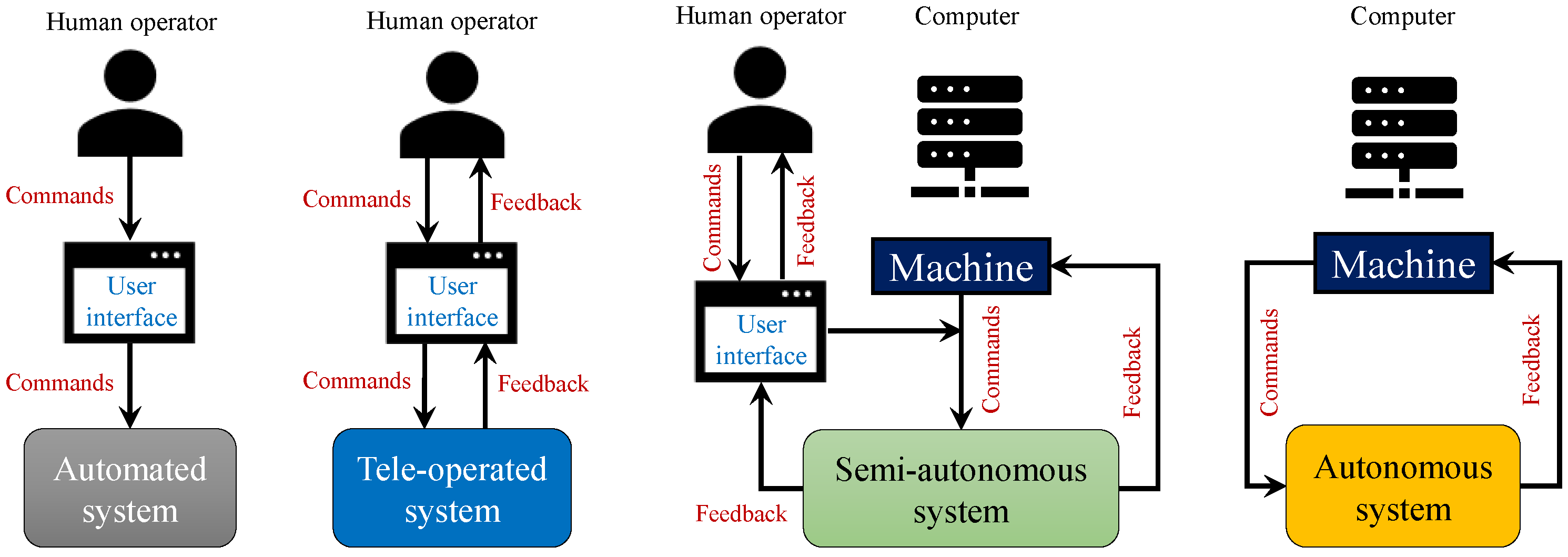
2. Systems Engineering Perspective

According to the International Council on Systems Engineering (INCOSE), a system is a “collection of different elements that together produce results not obtainable by the elements alone” [34]. Systems engineering is the study and design of systems, the components of which may be a variety of people, machines, processes, hardware, and other discrete things; the value of the system is in the benefit provided by the interaction of the various system elements. The main objective in system development is to ensure that the stakeholder needs are accomplished in a satisfactory way throughout the entire lifecycle of the system, in a reasonable time and at a reasonable cost. A number of system lifecycle models exist, some general and some adopted for specific domains. One of the most widely recognized is the SIMILAR process from Bahill & Gissing [35], a variation of which (created by the authors) is shown in Figure 3 below. This model is well suited for a semi-autonomous mowing system; this will be explored in more depth in Section 2.3 below.

2.1. Motivation for a Systems Engineering Perspective

While much previous work has been completed in the areas of path planning, navigation and obstacle avoidance, as well as development of complete semi-autonomous systems, there is need of a high-level, systems-focused approach to the development of these systems. A common theme in all of the reviewed studies was that they were approaching the problem as a sort of “new” area of study, resulting in a plethora of different approaches and wide variance in the level of success in different environments. It should be noted that a large number of the previous papers in this area are published in conference proceedings and not archival journals, which may make the status of the problem more difficult to understand since the proceedings are less organized and less available (in general) than journal articles would be. It could dramatically increase the pace of development if there was some kind of standard or development framework for these systems. Systems engineering theory could provide a good approach for accomplishing this, as it can provide a general “fill-in-the-blank” framework that is easy to organize and understand. The development of a unified approach to the design and analysis of mowers and other semi-autonomous systems will also greatly aid in the testing and certification of these systems.
One of the most important aspects of the system engineering approach will involve understanding the interfaces in the semi-autonomous mowing system, most especially the interface between the human user and the rest of the system. While there will be a number of subsystems within the whole framework, the three main interfaces at the top level will be between the human user, the system hardware, and the software (Figure 4). The rapid development in recent years of mobile technology provides a great opportunity for the further development of efficient and realistic consumer-level semi-autonomous lawn mowing systems. Advanced mobile platforms provide a very good natural interface between the human user and can be used to increase the confidence of users in the system. While the semi-autonomous mowing system may be a new and unfamiliar technology for the user, the mobile-based user interface could help the user learn how to use the system and making them feel more safe and familiar with it.

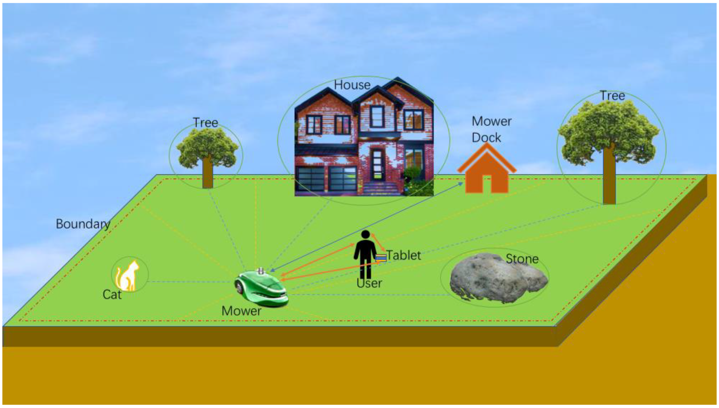
2.2. Concept of Operations (CONOPS)

The basic CONOPS for a general user-integrated semi-autonomous mowing system is shown in Figure 5. It is assumed that this kind of system is primarily for residential use and that a yard with a house and predicable and unpredictable obstacles is the operational space for the system. The basic elements of this operational space are the user and user interface (represented by a tablet), the mower, the ground to be mowed (i.e., the yard map), the base of operations (represented by the house), the mower base (charger, fuel, maintenance, etc., represented by the mower dock), the yard boundary, and a set of obstacles. The obstacles can be divided into three categories: (1) the predictable non-interfering obstacles (PNIOs) (represented by the rock), (2) the predictable interfering obstacles (PIOs) (represented by the trees), and (3) the unpredictable obstacles (represented by the cat).
The mowing system must have some method of localizing itself so that it can track its position and progress toward completion of the mowing job. The yard map may be generated by the user, by a UAV or ground tracking robot, or some other method; depending on the local conditions and the geometry of the yard, it may be necessary to map the yard at the beginning of each mowing job or it may only need to be done once when the mowing system is started for the first time. The map should be converted into an occupancy grid (statistical or binary) or other machine-readable data that the system can use to path plan and avoid obstacles. It is assumed for this kind of system that an on-board computer will be used on the mower to process all the needed data, run the autonomous part of the system, communicate with the user, and run the basic mower functions.
It must also be able to react to obstacles in some way, whether predicted obstacles (i.e., marked on the yard map) or unpredicted obstacles. The unpredicted obstacles (such as small animals, children’s toys, or other things will be missing from a standard mapping of the yard) must be tracked using some means, whether that is the use of a camera or LIDAR or whether the user is directly involved if such as obstacle is encountered. The predicted obstacles are already known to the system before mowing commences (via the occupancy grid or other map), as they were located by the mapping system or marked by the user. These will consist of PNIOs, which are things such as rocks, ponds, yard ornaments, and other things that are not tall enough or dense enough to interfere with the navigation and localization of the system. On the other hand, PNOs, such as cars, trees, and buildings, may interfere with the operation and communication of the system by blocking signals or GPS coverage. Care should be taken when setting up the system (e.g., placing the dock or locating beacons and kill wires for the system, and similar) to avoid these kinds of obstacles by default when possible. When using a UAV-based mapping, a feature of the analysis should be to locate any obstacles or potential obstacles that could interfere with signalling and localization and classify them as such.

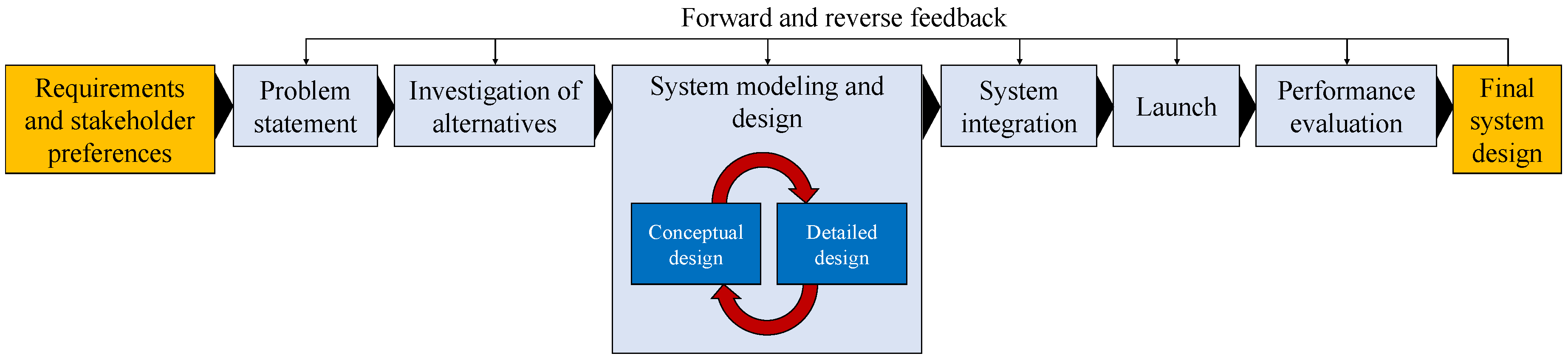
2.3. System View of User-Integrated, Semi-Autonomous Mowers

While there are many different types of systems engineering lifecycle models, the SIMILAR model previously discussed is a good starting place. The stakeholders may select a different model, but this is the one that the remainder of this paper will refer to as the “lifecycle model”. From a systems engineering perspective, there are several tasks to be completed when designing a user-integrated, semi-autonomous mowing system using a system approach; these can be divided up into two areas:
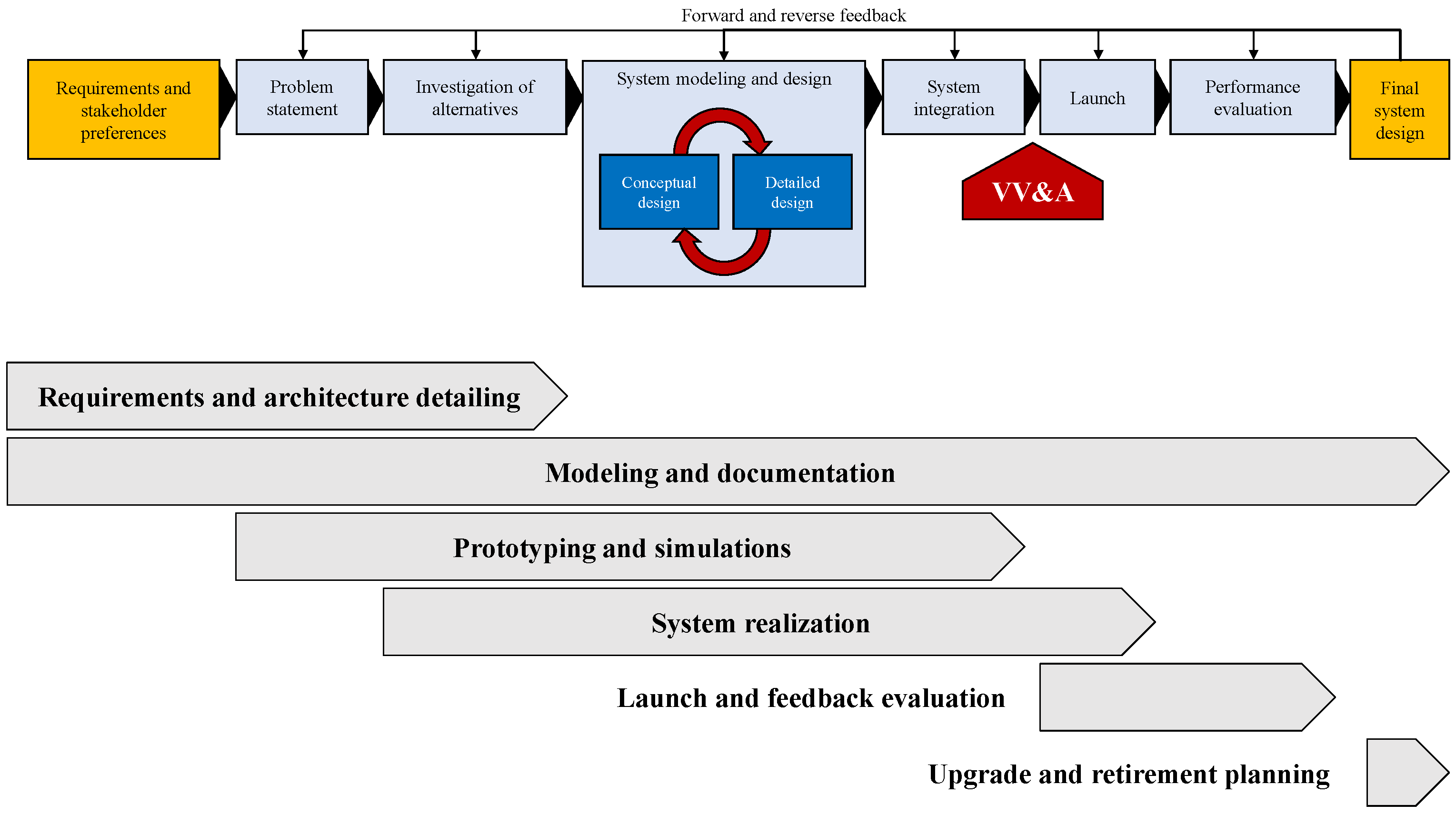
  • The lifecycle tasks: These include moving the system design along from step to step (Figure 3) to ensure an completed and useful system
  • The design and integration tasks within each of the steps
Operation in both of these areas could be considered to be systems engineering, as they deal with the whole system and its integration. As shown in the lifecycle model, the system requirements and stakeholder preferences must be the primary input to the lifecycle process; these must be developed for the system, a process that must be done by the stakeholders as early as possible in the process as these drive the rest of the system; this will be discussed in more depth in Section 3. These will drive the exact nature of the problem statement, which then drives the list of possible alternatives for the system. As discussed in Section 4, the choices made in these blocks would drive the system architecture. Once the architecture is established, the exact system design, integration, launch, and evaluation (including verification and validation of the system) follow naturally. The focus of the next two sections of this paper is on the requirements and architecture, since these drive the rest of the process for this kind of system. With a user-integration semi-autonomous mowing system, the most difficult part of the lifecycle process will be the development of the requirements and architecture. Note that this is a conceptual assessment of the system lifecycle process for such a lawn mowing system; this needs further development and evaluation to ensure that this process can actually be followed and completed successfully. However, historical experience (such as many NASA and aerospace programs which used similar lifecycle development processes) indicates that this is a reasonable and reliable approach that should ensure the successful design and integration of an effective system.

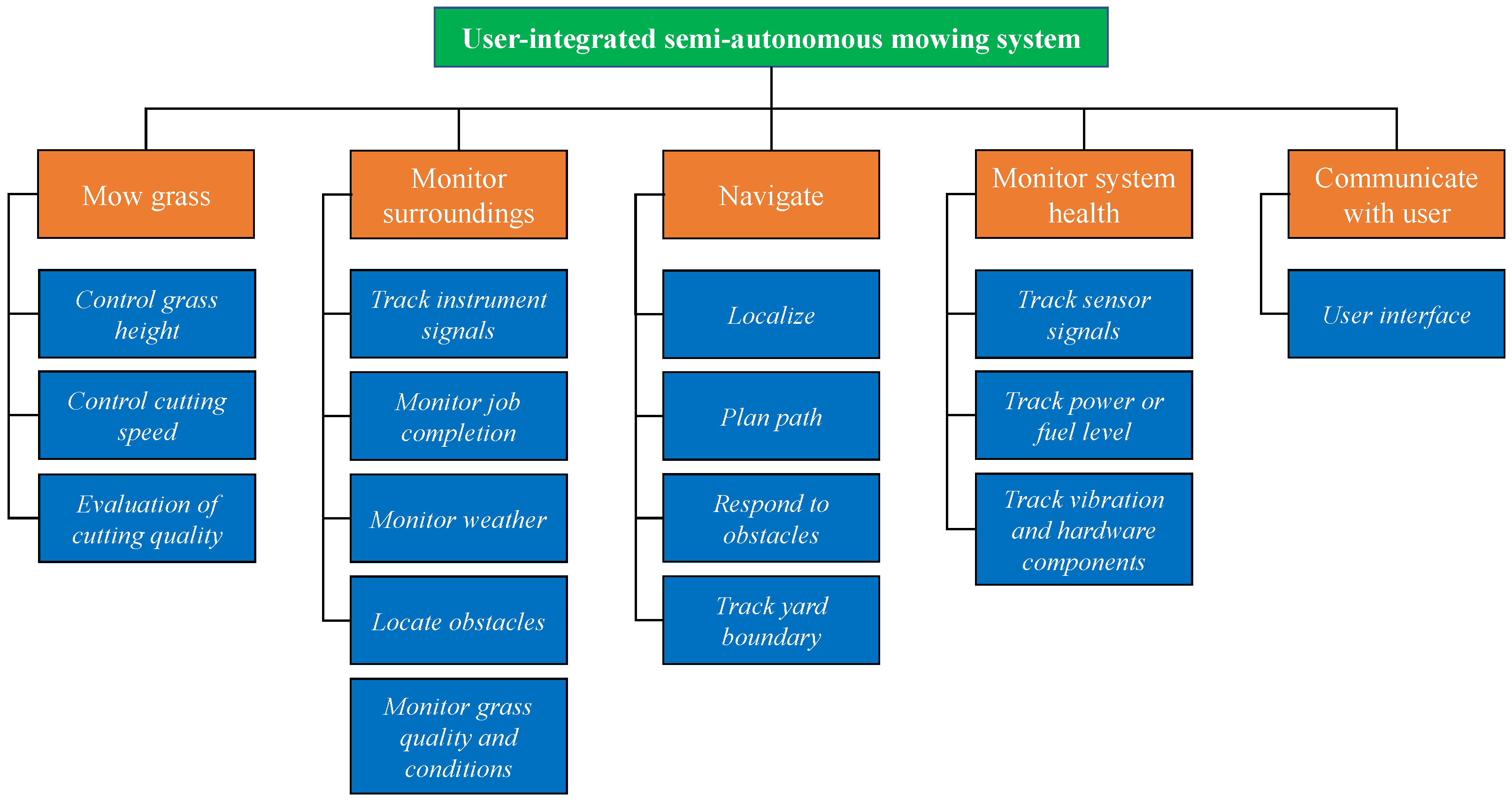
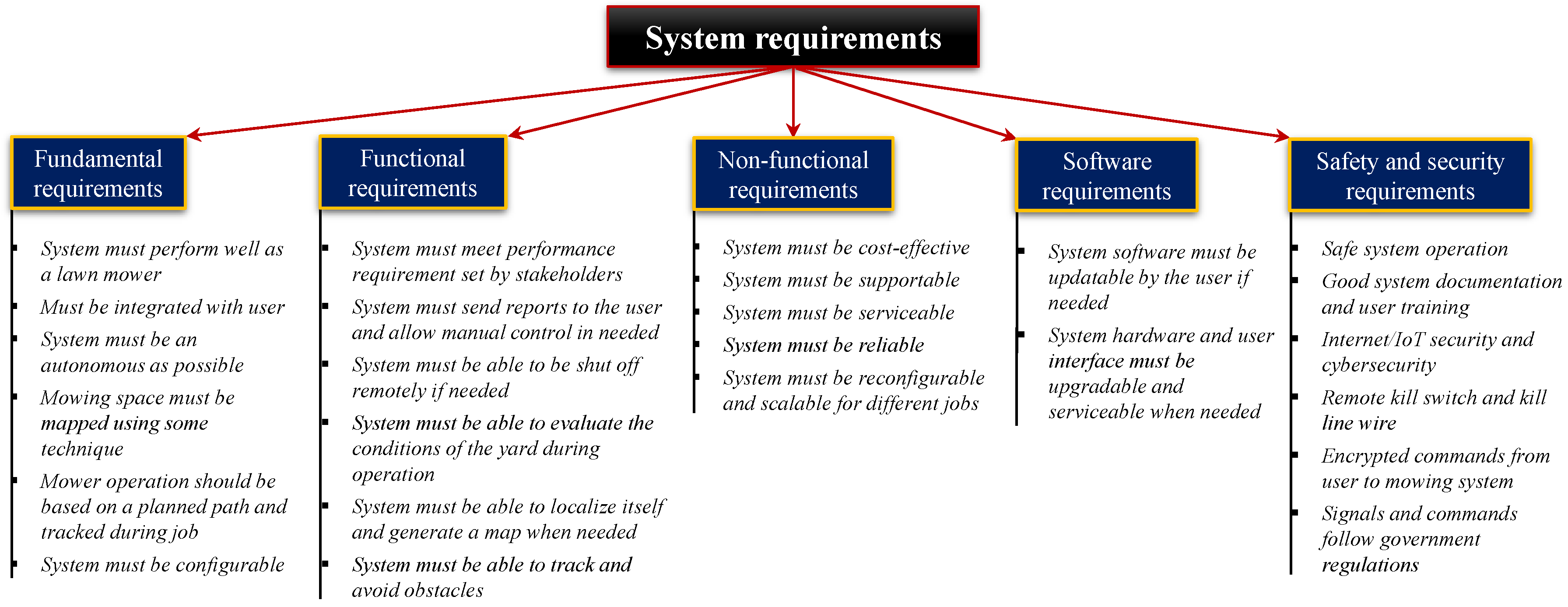
3. Basic, High-Level Requirements Development

The design and setup of any user-integrated semi-autonomous mowing system should follow a set of fundamental requirements, all of which are based on the needs and safety of the system and are not driven by a specific system. These standardized basic requirements are the starting place for the development of a system-specific set of requirements, driven from the needs and desires of the stakeholders. These top-level starting requirements can be divided up into five categories, namely (1) the fundamental requirements, (2) functional requirements, (3) non-functional requirements, (4) software requirements, and (5) the safety and security requirements. Figure 6 shows the tree diagram for these requirements with some example lower-level requirements to illustrate the relationship; note that these are for example only and the true system requirements will depend on the stakeholders needs and the operational conditions of the system being designed. The purpose of this outline is to give a starting place which will guide the development of the true system requirements in an organized, consistent, and (eventually) standardized way.
As shown in Figure 6, the best place to begin the development of a requirements document for this kind of system is to identify or specify the main requirements in each of the essential areas. These can be defined conceptually as:
  • Fundamental requirements: These are the most important high-level requirements, such as the expected basic performance and configuration of the system [37,38,39,40]. In the case of a user-integrated semi-autonomous mowing system, these requirements would be things such as requiring a basic user interface, that the system should have a significant degree of autonomy, that the system would function using a planned path and avoid obstacles, and that the space to be mowed must be mapped somehow and have a boundary identifiable by the mowing system.
  • Functional requirements: Since the fundamental requirements (i.e., “the system must do X”), the functional requirements are those related to performance and function of the system [39,40,41]. These may include things such as meeting minimal performance and efficiency requirements, being able to be remotely shut off in an emergency, being able to localize itself once the job is started, and other functional requirements.
  • Non-functional requirements: These would contain the bulk of the general requirements and deal with things such as reliability, serviceability, supportability, and cost effectiveness [37,42,43,44]. This list of requirements could be the most broad, as these may relate to things external to the system, such as local regulations and the desires of the user not related to mowing quality (e.g., color, noise level, IOS versus android user platform, etc.).
  • Software requirements: These requirements [45,46,47] would be separate from the other requirements, as the software used will likely be developed separate from the rest of the system and may be used in a wide variety of systems, similar to 3-D printer software packages such as Cura® and Repetier-Host®. The software development may also have a large influence on the development of the rest of the system, as it may impose operational constraints on the rest of the system. However, whether the software is open-source or proprietary, it should allow upgrades and bug and security fixes either by the user or pushed by the manufacturer. When possible, existing software libraries (such a Robotic Operating Systems (ROS) [48,49,50,51]) may be used to decrease the development risk [52,53]. However, in a commercial environment, the manufacturer may choose to use proprietary software for a variety of reasons; this is discussed in more depth in Section 5 on practical system implementation.
  • Safety and security requirements: It is vitally important for the system to be safe to use for the operator, any by-standers, and any animals or property that could be encountered by the mower. In addition, the system will need to connected to the internet (or at least a local network) and will have high-value hardware components, it is vital that robust physical and cyber security is implemented [38,54,55,56].
A more extensive and detailed suggested list of requirements for this kind of system can be found in the technical report “User-Integrated Semi-Autonomous Lawn Mowing Systems: Example Basic, Functional, Non-Functional, and Safety and Security Requirements” by the authors of this concept paper [36]. The technical report was meant to supplement this work and should be used in connection with it.

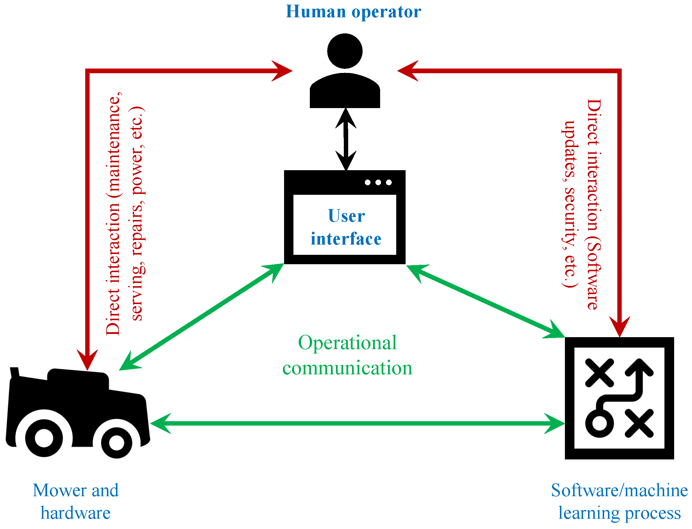
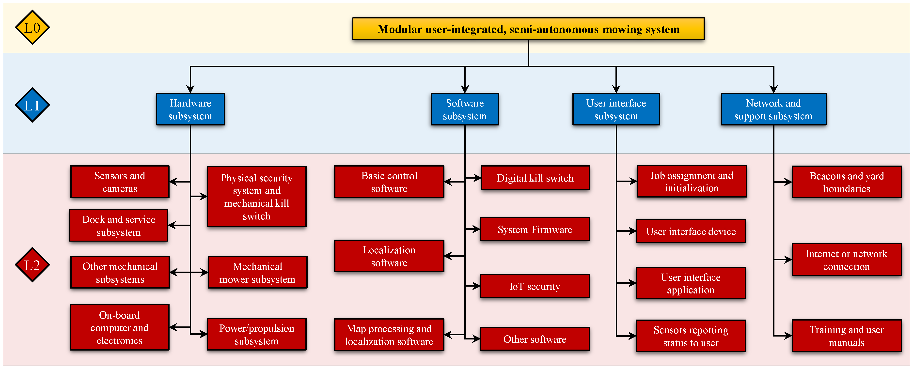
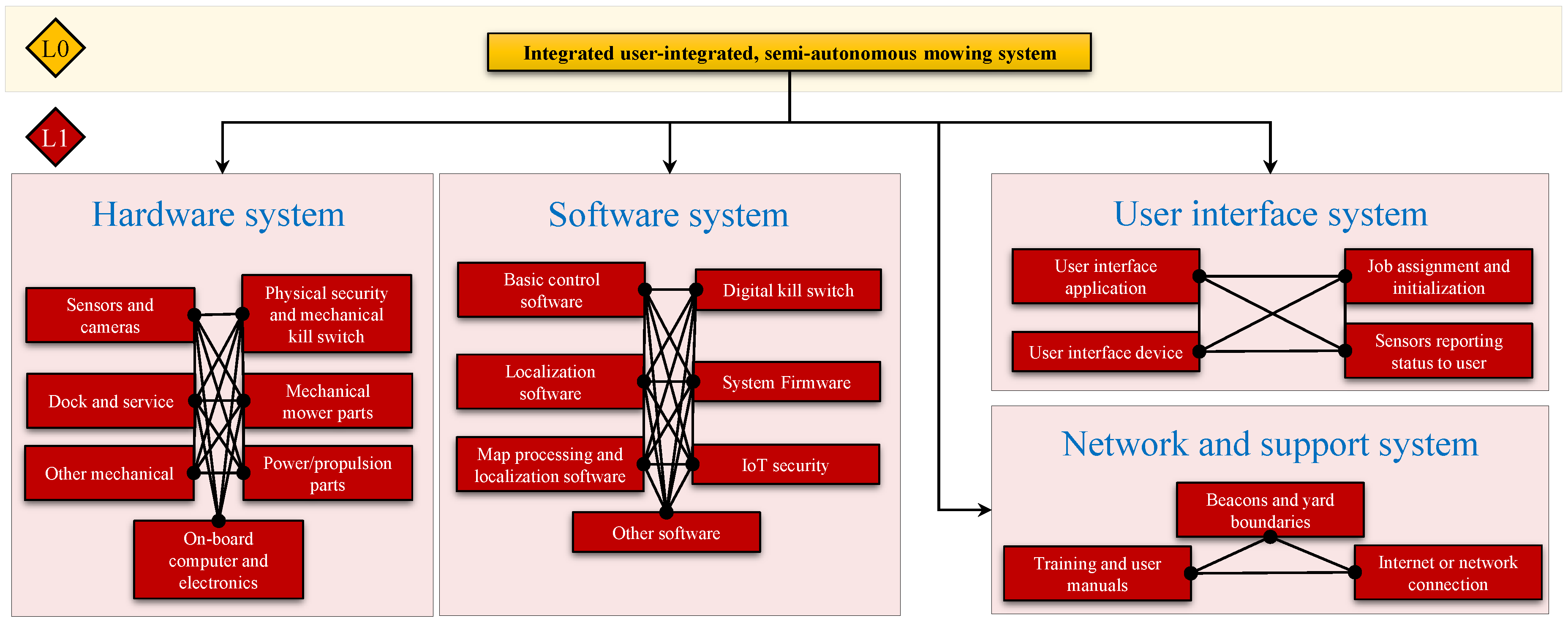
4. Proposed System Architecture

The physical architecture of a user-integrated, semi-autonomous mowing system will depend heavily on the specific design requirements developed by the stakeholders. Note that the architecture refers to the tangible parts of the system which can be designed; this does not refer to the functional aspects of the system, as several functions may be included in a single architecture element. For example, the weed detection, weather monitoring, and cutting speed/quality evaluation would be accomplished by sensors and the on-board vehicle computer; in this case, the computer and sensors are included in the architecture but not these specific functionalities.
The basic top-level architecture can be standardized if some fundamental system characteristics are used as the starting point in any design. These may be organized in a variety of ways, but the relationship between the essential items will remain the same regardless of the final detained design. In particular,
  • The user will interact with the working system through the user interface
  • The system will operate with some degree of autonomy with the user providing some of the monitoring, direction, and decision making
  • The hardware and software elements must interact through the sensors, the on-board computer, and the localization system
  • There must be some boundary elements for the yard for the localization engine and sensors to interact with
  • There must be some kind of secondary vision system in order to detect and react to unpredictable obstacles
  • There must be some method of producing a map of the yard, which will include locating and identifying PNIOs and PNOs
  • There must be a communication link between the system and the internet or a local wireless network
  • The system must have some kind of home base or dock for it to be secured, maintained, updated, recharged or refueled, and similar
These characteristics are important for any system design, so a logical way to understand and organize them from a system perspective will be helpful in standardizing the system design process. Therefore, this paper proposes a high-level system architecture which divides the system unto a series of parts and interfaces. Three cases are possible, namely (1) a modular system, (2) an integrated system, and (3) a hybrid system. The basic relationship between the three configurations related to the optimizability and system customizability/re-configurability is shown in Figure 7. Note that (also shown in Figure 7) the system reliability will be generally inversely correlated with the number of interfaces in the system, as it is well-known in the systems engineering literature that the system interfaces are the typical points of failure in most systems [57,58,59,60,61,62,63,64,65]. This is especially true with a modular system like the one described in this paper, since most of the components/subsystems will be connected in a series configuration. This is of course a very simplified view of the system and the actual degree of influence will depend on many factors in the final system design itself. It is however a very important consideration that cannot be ignored when selecting what basic system architecture to use.
Clearly, there is a trade-off for using either basic architecture and which is appropriate is dependent on the needs and wished of the stakeholders; however, it is the opinion of the authors that a hybrid system will usually be the most appropriate choice. Note that in any case, the system hardware and software will be considered different subsystems, as realistically they will likely be developed by separate design teams and later integrated together. In addition, it would be very difficult to integrate the user interface and network and support systems into the main system. Therefore, in all three cases, there will be four divisions of the system at the top architecture level.
In a pure modular system, the architecture is divided into a series of subsystems, which are in turn composed of modular hardware and software components down to the level of the individual element. However, this type of system is rare and usually very inefficient since all components must be modular, easily replaceable, and easily available for replacement. This prevents much optimization of the system, but gives the highest level of system flexibility. Designing such a system with strictly standardized parts and open-source hardware and software may provide an attractive option to some customers who would use it as a hobby project. However, with the current status of the autonomous vehicle technology and the safety hazards involved, this would likely present too much liability for a consumer product.
In this case, the top four subsystems would consist of the hardware subsystem, the software subsystem, the user interface subsystem, and the network and support subsystem; Figure 8 shows the first three levels of the architecture, enough to establish the system configuration and basic layout. Note that each of the red (L2) items may be individual components or subsystems depending on the final design and the final set of design and performance requirements set by the stakeholders. Within the hardware subsystem would be the mechanical mower components, the power/propulsion source, the sensors, the on-board computer, the dock, and similar mechanical items. The software subsystem would contain the base control software (itself perhaps a modular build), the localization software, the mapping and map processing software, the digital kill switch, the firmware for the system, and other important software parts and subsystems. The user interface subsystem will consist of things related to the user experience and control of the system, containing both hardware and software components such as the interface device, the application software to run it, and the sensors to give updates and reports to the user as the job is being completed. Finally, the network and support subsystem consists of the user training materials, the beacons/navigation markers for the system, and the network connection for the mower. The integrated system contains the same basic elements and functions as the modular system, but is fully integrated within each of the main system divisions. There are only two levels in this case, since the system is not modular. Note that there may be modular components within each of the main system functions but ideally the system is entirely integrated. Figure 9 demonstrates an example architecture with each of the major subsystem elements integrated together into the four main system divisions previously discussed. Likely the most useful and practical case would be the hybrid system architecture, which combines elements of both the modular and hybrid cases to find a good balance between system flexibility and optimizability. For example, (Figure 10), it could be decided by the stakeholders to use an integrated software system while making the rest of the system modular. There is a nearly infinite number of combinations possible for a hybrid system, ranging from 99.9% modular to 99.9% integrated, so this configuration is shown only for demonstration purposes.

5. Practical Implementation Considerations

When designing any system using a lifecycle process, there are several areas where practical implementation consideration and strategies derived or decided by the stakeholders are needed. These can be divided into seven major activities, namely (1) requirements and architecture detailing, (2) modeling and documentation, (3) prototyping and simulations, (4) system realization, (5) verification, validation, and accreditation (VV&A), (6) launch and feedback collection, and (7) planning upgrades and retirement. Looking at the steps in the SIMILAR process (Figure 3), these activities do not correspond directly with the design lifecycle steps. In general, the requirements and architecture detailing should be done before the beginning of the system design, while the modeling and documentation should be done at all steps in the process. Prototyping and simulations, as well as many of the system realization activities, will happen in the alternative investigations, in the system design, and in system integration and launch phases. Once the system is integrated and prior to launch, the VV&A activities will be required, as the system cannot be launched without this step being completed. The launch and feedback tasks correspond with those in the model, while the upgrade and retirement planning is done after system design is completed. It should be noted that some system lifecycle models (notably the NASA SE Engine [66]) include system retirement as a fundamental lifecycle block, but this is not shown here for consistency with the lifecycle model selected. Figure 11 shows the SIMILAR process again with the various implementation phases shown relative to the basic conceptual lifecycle domains. This section will discuss some major practical implementation strategies for the first five of these areas.

5.1. Requirements and Architecture Detailing

A set of basic requirements and general architecture for a user-integrated semi-autonomous mowing system were given in Section 3 and Section 4, respectively. The refinement of the requirements must be done before the architecture, as it will drive the architecture details. The exact requirements for the system under development will need to be carefully specified by the stakeholders, as discussed in Section 3. Once this is done, the stakeholders must determine the type of system (modular, integrated, or hybrid) that the mower should be. When possible, historical examples should be used to guide the selection. The trade-off between modular and integrated designs should also be considered, as this will determine the quality of the design in a major way. In general, the modular system will be more flexible, lower cost, easier for the user to modify as needed, and will be more easily upgradable. On the other hand, the integrated system will generally be more efficient, with more optimal performance, and less at risk of technology loss (when proprietary system elements are used) and will likely be more reliable; however, it will be much more difficult to upgrade as the technology develops. Some further reading, lessons-learned, and directions for system requirements and architecture detailing can be found in [66,67,68,69,70].

5.2. Modeling and Documentation

Careful modeling and documentation must be done throughout the lifecycle process [42,71,72]. In addition to being a good engineering practice, this will ensure that waste of effort, time, and resources is kept to a minimum. It will be also be vital for the effective testing and verification of the system once the design is completed. With a user-integrated semi-autonomous mowing system, the stakeholders should keep in mind that the system will need to work with a human user and will encounter various animals and plants during its use, some of which it will need to negotiate with without doing any harm to them. System safety will be paramount in order to ensure that the system is beneficial to the human user and does not present an additional risk to them. The stakeholders should also keep in mind that many of the technologies that will be necessary for successful implementation of a semi-autonomous mowing system are immature and their reliability in all cases is unknown. The continued use of robotics in agriengineering has great potential for the future, but part of this will depend on avoiding negative experiences or risks to the human users. Since this system is semi-autonomous, the user will still be involved and make some of the operational decisions, so there can be a strong example of human-robot interaction which may serve to increase or decrease the trust in robotic systems by human users. Careful modeling and documentation of the problem and solution can help to find problems early and reduce the risk of system risks/unreliabilities which may bias the user against human-robot cooperation in the future.

5.3. Prototyping and Simulations

Similarly to the modeling and documentation, rigorous prototyping and simulation of the system can help to increase design quality and decrease the risks associated with a user-integrated robotic system, especially one that will be used in a residential setting and potentially interact regularly with humans. Care should be taken when completing these tasks to follow and document the work using standard practices and accepted notation. This will be very important for rigorous design, as well as for error tracking and for future development of the system design. Some practical guidelines and concepts for robotic system prototyping and simulation can be found in [73,74,75,76,77,78,79]. As desired by the stakeholders and appropriate for the system under design, some well-developed (including some open-source) tools are available for completing the system prototyping and simulation tasks without the need for additional tool or process development [80,81,82,83,84,85,86,87].

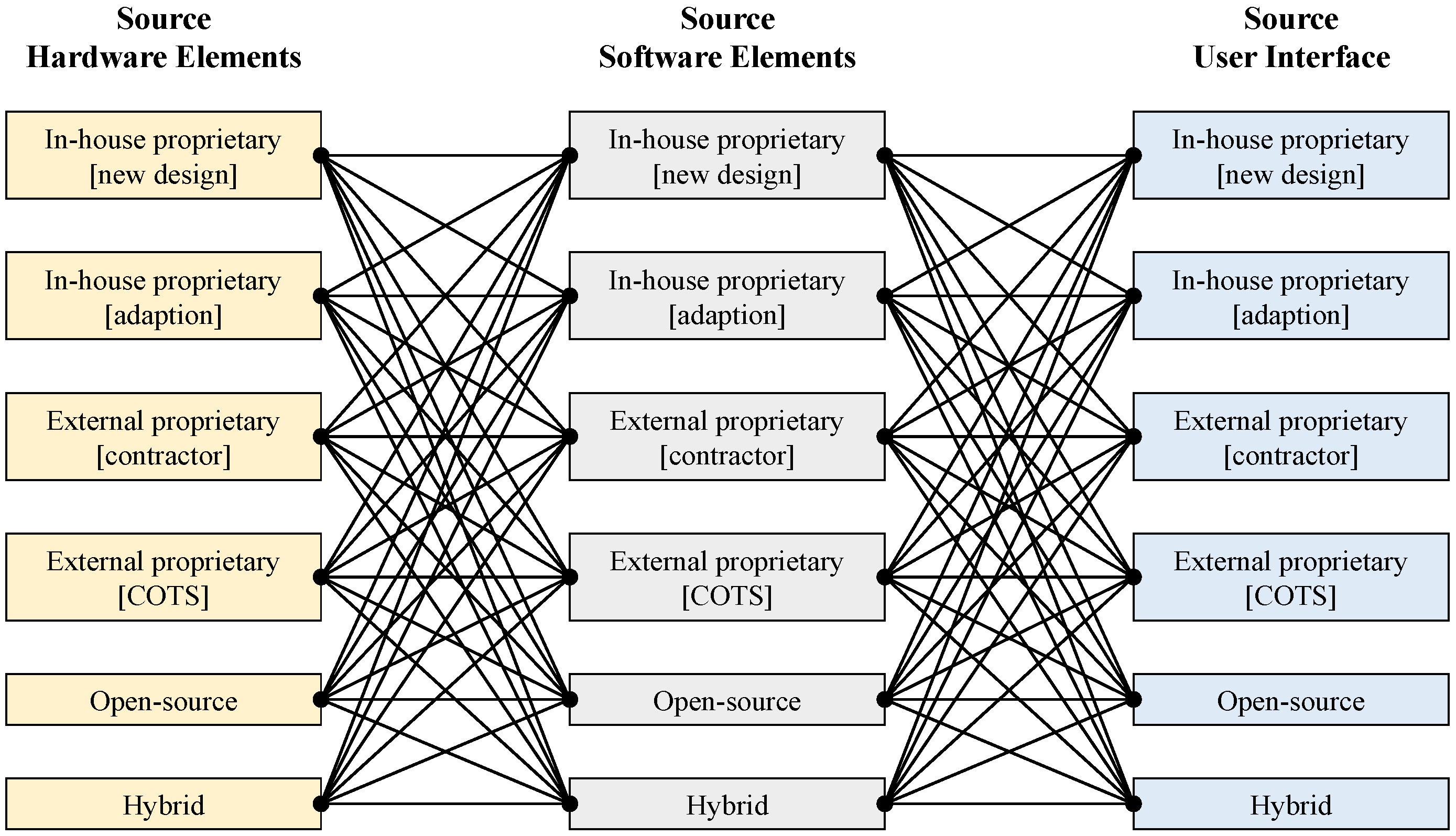
5.4. System Realization

Once the requirements and architecture are refined and the system is well-documented, it must be “realized” (i.e., physically built). A previously described, a user-integrated semi-autonomous mowing system has three main top-level components, namely the set of hardware elements, the set of software elements, and the user interface. The hardware elements are things such as the cutting and propulsion systems, the power system (battery or internal combustion engine), the sensors for tracking the cutting progress and detecting obstacles, the on-board computer, the physical safety systems, and such. The the software components are the main control system, the sensor tracking system, the safety system, the navigation and localization engine, and similar important items. The user interface can take a variety of forms, the simplest which would be in the form of an application that the user would load into their existing smartphone or tablet.
For each of the components, the design will depend partially on the source and development strategy. As shown in Figure 12, there are many possible combinations of development strategies for each of the components. For each of the components (hardware, software, and user interface), its development plan could be one of several things:
  • In-house proprietary-new design: The lab or company building the mowing system will develop the component from scratch and use a new design under this OEM. This component is assumed to be made only for the mowing system under development and is optimized for it.
  • In-house proprietary-adaption: The lab or company building the mowing system selects or adapts an existing proprietary component (internally-developed) to use on the mowing system.
  • External proprietary-contractor: Similar to #1 but the mower system manufacturer does not have the capability so the component is out-sourced to a contractor to produce
  • External proprietary-COTS: This is the adoption or adaption of a proprietary (external) but commercial off-the-shelf (COTS) component in the mowing system
  • Open source: The component is an open-source design that can be used and adapted freely. This will be especially useful in the development of the software components, as Robot Operating Systems (ROS) [48,49,50,88,89] are available, as well as other open-source tools such as OpenCV [90] for machine vision. ROS can provide a wide variety of important software packages which can be used as-is or as a template for the actual software used; particularly useful packages include SLAM, pose estimation, firmware, and sensor fusion [48,89]. Open source software (and hardware) is very useful in the research arena and can save a lot of time and effort during development. They may also be useful in some applications on the commercial side, but this must be a decision by the stakeholders and not something that can be hard-wired into a system design framework. It is well-known that open-source, wide-use hardware and software (such as kit robots and ROS) are generally less reliable and efficient that single-use, purpose-built proprietary elements [51,91,92,93], but they may be appropriate and even desirable for some commercial designs. Therefore, the use will depend also on the domain of applicability, the amount of control the producer grants to the user, and the goals of the design.
  • Hybrid The development strategy for the component or subsystem which is a hybrid of the previously described strategies

5.5. Verification, Validation, and Accreditation

Once the system design is completed (or at least the first iteration of the design in the form of a prototype), the next step is to ensure that all requirements are satisfied (verification), that the requirements captured all the system aspects (validation), and independent evaluation shows the system behaves as intended (accreditation). This will involve a significant amount of physical testing, so a rigorous testing plan should be followed, with clearly defined success criteria and variables. This may be a proprietary plan developed by the design team or may be a standardized testing plan commonly used in the industry. When possible, standards should be followed closely to ensure a correct and complete testing course and that the test results are credible. As previously discussed, it is likely that the developing technologies that need to be used in a semi-autonomous mowing system will present some challenges; in addition to finding the true performance envelope for the lawn mowing system under development, it is also an opportunity to further develop the technologies (e.g., navigation, path planning, etc.) so all problems and solutions encountered should be carefully documented and provided to research groups working in those areas whenever possible. References [94,95,96,97,98,99] provide some additional discussion and guidelines for setting up and completing VV&A processes.

6. Conclusions and Final Remarks

This concept paper laid out some recent work by the authors toward the development of a systems engineering perspective on the design of user-integrated, semi-autonomous mowing systems. The paper began with an extensive literature review to find the current status of development for this kind of system, with the conclusion that the literature is sparse in some areas and does not seem to be focused around any kind of standard method or perspective. A systems engineering perspective in the design of these systems was then presented, including an in-depth discussion of the systems engineering process, a CONOPS to demonstrate the problem, and an examination of the system design considerations for the problem. An initial set of general requirements (seed requirements) and a general architecture were proposed to give a good starting place for the design and development of these systems. Finally, a detailed look at some practical considerations for the system-level design of user-integrated semi-autonomous mowing systems is given, focusing on the requirements and architecture, the system modeling and documentation, prototyping and simulation, the system realization, and the VV&A of the system.
This work is meant to provoke a discussion and interest in the engineering and robotics communities and help to start developing a standardized and consistent perspective for the future development of refinement of these and other kinds of user-integrated semi-autonomous systems. This work should serve as a starting place for the research community (both commercial and academic) to improve and develop a systems engineering method for these systems, hopefully culminating in a universal design approach and useful industry standards related to semi-autonomous and autonomous systems in the future.

7. Important Future Work Directions

There are a number of areas within this topic that need further research. In addition to the basic development of the needed technologies (software, sensors, navigation, image processing, etc.), some areas that should be considered in future research efforts are:
  • Development of test courses for the VV&A of semi-autonomous mowing systems
  • Development and refinement of user interfaces that can be used with these and other types of mowing systems
  • Assessment of the reliability of the system and various system components, especially any hardware and sensors mounted on the robot
  • Mowing robots may be subject to more vibration (both regular and unexpected) than other robotic systems - the effects of this on performance and reliability should be evaluated
  • Develop a user training program for operating, maintaining, and repairing a user-integrated semi-autonomous mowing system
  • A comparison of performance and trade-offs between power sources for the robot are needed. Unlike many robotic systems it is feasible, and perhaps even desirable, to use a small internal combustion engine as a power source for this kind of system. Comparison with a battery-driven system is essential in future studies.

Author Contributions

A.E.P. and Y.Y. performed the background review and developed the architecture and requirements, A.E.P. introduced the design and systems perspectives and discussion, Y.Y. created the CONOPS, W.R.N. provided the overall problem statement, and guided the development of the system architecture. All authors contributed the writing and editing of the manuscript.

Funding

This work received no external funding.

Acknowledgments

The authors would like to thank the editor and the three anonymous reviewers for their extensive and helpful comments and suggestions on this work.

Conflicts of Interest

The authors declare no conflict of interest. Opinions and conclusions presented in this work are solely those of the authors.

References

  1. Grand View Research. Lawn Mowers Market Size, Share & Trends Analysis Report by Product (Petrol, Electric, Manual, Robotic), by End Use (Residential, Commercial & Govt.), by Region (MEA, Asia Pacific, North America), and Segment Forecasts, 2019–2025. Technical Report. 2019. Industry Report Number GVR-1-68038-927-2. Available online: https://www.grandviewresearch.com/industry-analysis/lawn-mowers-market (accessed on 23 June 2019).
  2. Tribelhorn, B.; Dodds, Z. Evaluating the Roomba: A low-cost, ubiquitous platform for robotics research and education. In Proceedings of the 2007 IEEE International Conference on Robotics and Automation, Roma, Italy, 10–14 April 2007; pp. 1393–1399. [Google Scholar] [CrossRef]
  3. Aponte-Roa, D.A.; Collazo, X.; Goenaga, M.; Espinoza, A.A.; Vazquez, K. Development and Evaluation of a Remote Controlled Electric Lawn Mower. In Proceedings of the 2019 IEEE 9th Annual Computing and Communication Workshop and Conference (CCWC), Las Vegas, NV, USA, 7–9 January 2019. [Google Scholar] [CrossRef]
  4. Hicks, R.W., II; Hall, E.L. Survey of robot lawn mowers. In Intelligent Robots and Computer Vision XIX: Algorithms, Techniques, and Active Vision; Casasent, D.P., Ed.; SPIE: Bellingham, WA, USA, 2000. [Google Scholar] [CrossRef]
  5. Sahin, H.; Givenc, L. Household robotics: Autonomous devices for vacuuming and lawn mowing [Applications of control]. IEEE Control Syst. 2007, 27, 20–96. [Google Scholar] [CrossRef]
  6. Gregg, M.; Schwartz, E.M.; Arroyo, A.A. Autonomous lawn care applications. In Proceedings of the 2006 Florida Conference on Recent Advances in Robotics, Miami, FL, USA, 25–26 May 2006. [Google Scholar]
  7. Norris, W.R.; Patterson, A.E. Automation, Autonomy, and Semi-Automomy: A Brief Definition Relative to Robotics and Machine Systems; Technical Report; University of Illinois at Urbana-Champaign: Champaign, IL, USA, 2019; Available online: http://hdl.handle.net/2142/104214 (accessed on 15 July 2019).
  8. Shiu, B.M.; Lin, C.L. Design of an autonomous lawn mower with optimal route planning. In Proceedings of the 2008 IEEE International Conference on Industrial Technology, Chengdu, China, 21–24 April 2008. [Google Scholar] [CrossRef]
  9. Nourani-Vatani, N.; Bosse, M.; Roberts, J.; Dunbabin, M. Practical path planning and obstacle avoidance and autonomous mowing. In Proceedings of the Australasian Conference on Robotics and Automation, Auckland, New Zealand, 6–8 December 2006. [Google Scholar]
  10. Wasif, M. Design and implementation of autonomous Lawn-Mower Robot controller. In Proceedings of the 2011 7th International Conference on Emerging Technologies, Islamabad, Pakistan, 5–6 September 2011. [Google Scholar] [CrossRef]
  11. Daltorio, K.A.; Rolin, A.D.; Beno, J.A.; Hughes, B.E.; Schepelmann, A.; Branicky, M.S.; Quinn, R.D.; Green, J.M. An obstacle-edging reflex for an autonomous lawnmower. In Proceedings of the IEEE/ION Position, Location and Navigation Symposium, Indian Wells, CA, USA, 4–6 May 2010; pp. 1079–1092. [Google Scholar] [CrossRef]
  12. Peless, E.; Abramson, S.; Dror, G. Navigation Method and System for Autonomous Machines with Markers Defining the Working Area. Patent Number US6984952B2, 10 January 2006. Available online: https://patents.google.com/patent/US6984952 (accessed on 15 July 2019).
  13. Samad, A.M.; Kamarulzaman, N.; Hamdani, M.A.; Mastor, T.A.; Hashim, K.A. The potential of Unmanned Aerial Vehicle (UAV) for civilian and mapping application. In Proceedings of the 2013 IEEE 3rd International Conference on System Engineering and Technology, Shah Alam, Malaysia, 19–20 August 2013; pp. 313–318. [Google Scholar] [CrossRef]
  14. Choi, J.; Lee, J.; Kim, D.; Soprani, G.; Cerri, P.; Broggi, A.; Yi, K. Environment-Detection-and-Mapping Algorithm for Autonomous Driving in Rural or Off-Road Environment. IEEE Trans. Intell. Transp. Syst. 2012, 13, 974–982. [Google Scholar] [CrossRef]
  15. Franzius, M.; Dunn, M.; Einecke, N.; Dirnberger, R. Embedded Robust Visual Obstacle Detection on Autonomous Lawn Mowers. In Proceedings of the 2017 IEEE Conference on Computer Vision and Pattern Recognition Workshops (CVPRW), Honolulu, HI, USA, 21–26 July 2017. [Google Scholar] [CrossRef]
  16. Schepelmann, A.; Hudson, R.E.; Merat, F.L.; Quinn, R.D. Visual segmentation of lawn grass for a mobile robotic lawnmower. In Proceedings of the 2010 IEEE/RSJ International Conference on Intelligent Robots and Systems, Taipei, Taiwan, 18–22 October 2010; pp. 734–739. [Google Scholar] [CrossRef]
  17. Guo, Y.; Sun, F. Efficient visual obstacle avoidance for robotic mower. In Proceedings of the 2017 2nd International Conference on Control and Robotics Engineering (ICCRE), Bangkok, Thailand, 1–3 April 2017; pp. 23–28. [Google Scholar] [CrossRef]
  18. Zhang, L.; Verma, B.; Stockwell, D.; Chowdhury, S. Density Weighted Connectivity of Grass Pixels in image frames for biomass estimation. Expert Syst. Appl. 2018, 101, 213–227. [Google Scholar] [CrossRef] [Green Version]
  19. Bai, J.; Lian, S.; Liu, Z.; Wang, K.; Liu, D. Deep Learning Based Robot for Automatically Picking Up Garbage on the Grass. IEEE Trans. Consum. Electron. 2018, 64, 382–389. [Google Scholar] [CrossRef] [Green Version]
  20. Kounalakis, T.; Malinowski, M.J.; Chelini, L.; Triantafyllidis, G.A.; Nalpantidis, L. A Robotic System Employing Deep Learning for Visual Recognition and Detection of Weeds in Grasslands. In Proceedings of the 2018 IEEE International Conference on Imaging Systems and Techniques (IST), Krakow, Poland, 16–18 October 2018. [Google Scholar] [CrossRef]
  21. Choset, H. Coverage for robotics—A survey of recent results. Ann. Math. Artif. Intell. 2001, 31, 113–126. [Google Scholar] [CrossRef]
  22. Choset, H.; Pignon, P. Coverage Path Planning: The Boustrophedon Cellular Decomposition. In Field and Service Robotics; Springer: London, UK, 1998; pp. 203–209. [Google Scholar] [CrossRef] [Green Version]
  23. Acar, E.U.; Choset, H.; Rizzi, A.A.; Atkar, P.N.; Hull, D. Morse Decompositions for Coverage Tasks. Int. J. Robot. Res. 2002, 21, 331–344. [Google Scholar] [CrossRef]
  24. Wong, S.; MacDonald, B. A topological coverage algorithm for mobile robots. In Proceedings of the 2003 IEEE/RSJ International Conference on Intelligent Robots and Systems (IROS 2003) (Cat. No.03CH37453), Las Vegas, NV, USA, 27–31 October 2003; pp. 1685–1690. [Google Scholar] [CrossRef]
  25. Yao, Z. Finding Efficient Robot Path for the Complete Coverage of A Known Space. In Proceedings of the 2006 IEEE/RSJ International Conference on Intelligent Robots and Systems, Beijing, China, 9–15 October 2006; pp. 3369–3374. [Google Scholar] [CrossRef]
  26. Elhoseny, M.; Tharwat, A.; Hassanien, A.E. Bezier Curve Based Path Planning in a Dynamic Field using Modified Genetic Algorithm. J. Comput. Sci. 2018, 25, 339–350. [Google Scholar] [CrossRef]
  27. Darwish, A.H.; Joukhadar, A.; Kashkash, M. Using the Bees Algorithm for wheeled mobile robot path planning in an indoor dynamic environment. Cog. Eng. 2018, 5. [Google Scholar] [CrossRef]
  28. Ferrer, G.; Sanfeliu, A. Anticipative kinodynamic planning: multi-objective robot navigation in urban and dynamic environments. Auton. Robot. 2018, 43, 1473–1488. [Google Scholar] [CrossRef]
  29. Liu, H.; Ma, J.; Huang, W. Sensor-based complete coverage path planning in dynamic environment for cleaning robot. CAAI Trans. Intell. Technol. 2018, 3, 65–72. [Google Scholar] [CrossRef]
  30. Reinhart, R.; Shareef, Z.; Steil, J. Hybrid Analytical and Data-Driven Modeling for Feed-Forward Robot Control †. Sensors 2017, 17, 311. [Google Scholar] [CrossRef] [PubMed]
  31. Wei, K.; Ren, B. A Method on Dynamic Path Planning for Robotic Manipulator Autonomous Obstacle Avoidance Based on an Improved RRT Algorithm. Sensors 2018, 18, 571. [Google Scholar] [CrossRef] [PubMed]
  32. Pham, D.; Ghanbarzadeh, A.; Koç, E.; Otri, S.; Rahim, S.; Zaidi, M. The Bees Algorithm—A Novel Tool for Complex Optimisation Problems. In Intelligent Production Machines and Systems; Elsevier: Amsterdam, The Netherlands, 2006; pp. 454–459. [Google Scholar] [CrossRef]
  33. Kuusniemi, H.; Wieser, A.; Lachapelle, G.; Takala, J. User-level reliability monitoring in urban personal satellite-navigation. IEEE Trans. Aerosp. Electron. Syst. 2007, 43, 1305–1318. [Google Scholar] [CrossRef]
  34. Walden, D.; Roedler, G.; Forsberg, K.; Hamelin, R.; Shortell, T. INCOSE Systems Engineering Handbook: A Guide for System Life Cycle Processes and Activities, 4th ed.; John Wiley & Sons: Hoboken, NJ, USA, 2015. [Google Scholar]
  35. Bahill, A.; Gissing, B. Re-evaluating systems engineering concepts using systems thinking. IEEE Trans. Syst. Man Cybern. Part C (Appl. Rev.) 1998, 28, 516–527. [Google Scholar] [CrossRef]
  36. Yuan, Y.; Patterson, A.E.; Patterson, T.L.; Norris, W.R. User-Integrated Semi-Autonomous Lawn Mowing Systems: Example Basic, Functional, Non-Functional, and Safety and Security Requirements; Technical Report; University of Illinois at Urbana-Champaign: Champaign, IL, USA, 2019; Available online: http://hdl.handle.net/2142/104210 (accessed on 15 July 2019).
  37. Katina, P.F.; Keating, C.B.; Jaradat, R.M. System requirements engineering in complex situations. Requir. Eng. 2012, 19, 45–62. [Google Scholar] [CrossRef]
  38. Pattar, S.; Buyya, R.; Venugopal, K.R.; Iyengar, S.S.; Patnaik, L.M. Searching for the IoT Resources: Fundamentals, Requirements, Comprehensive Review, and Future Directions. IEEE Commun. Surv. Tutor. 2018, 20, 2101–2132. [Google Scholar] [CrossRef]
  39. Long, J.E. Relationships between common graphical representations used in system engineering. INSIGHT 2018, 21, 8–11. [Google Scholar] [CrossRef]
  40. Ambreen, T.; Ikram, N.; Usman, M.; Niazi, M. Empirical research in requirements engineering: Trends and opportunities. Requir. Eng. 2016, 23, 63–95. [Google Scholar] [CrossRef]
  41. Guevara-Vega, C.P.; Guzmán-Chamorro, E.D.; Guevara-Vega, V.A.; Andrade, A.V.B.; Quiña-Mera, J.A. Functional Requirement Management Automation and the Impact on Software Projects: Case Study in Ecuador. In Advances in Intelligent Systems and Computing; Springer: Berlin, Germany, 2019; pp. 317–324. [Google Scholar] [CrossRef]
  42. Adams, K.M. Nonfunctional Requirements in Systems Analysis and Design; Springer: Berlin, Germany, 2015. [Google Scholar] [CrossRef]
  43. Sun, P.; Yang, J.; Ming, H.; Chang, C.K. A Multi-layered Desires Based Framework to Detect Users’ Evolving Non-functional Requirements. In Proceedings of the 2018 IEEE 42nd Annual Computer Software and Applications Conference (COMPSAC), Tokyo, Japan, 23–27 July 2018. [Google Scholar] [CrossRef]
  44. Niu, N.; Brinkkemper, S.; Franch, X.; Partanen, J.; Savolainen, J. Requirements Engineering and Continuous Deployment. IEEE Softw. 2018, 35, 86–90. [Google Scholar] [CrossRef] [Green Version]
  45. Nazaruka, E.; Osis, J. The Formal Reference Model for Software Requirements. In Communications in Computer and Information Science; Springer: Berlin, Germany, 2019; pp. 352–372. [Google Scholar] [CrossRef]
  46. Curcio, K.; Navarro, T.; Malucelli, A.; Reinehr, S. Requirements engineering: A systematic mapping study in agile software development. J. Syst. Softw. 2018, 139, 32–50. [Google Scholar] [CrossRef]
  47. Haq, S.U.; Gu, D.; Liang, C.; Abdullah, I. Project governance mechanisms and the performance of software development projects: Moderating role of requirements risk. Int. J. Proj. Manag. 2019, 37, 533–548. [Google Scholar] [CrossRef]
  48. ROS. Available online: https://www.ros.org/ (accessed on 11 August 2019).
  49. Koubaa, A. Robot Operating System (ROS); Springer: Berlin, Germany, 2016. [Google Scholar]
  50. Boren, J.; Cousins, S. Exponential Growth of ROS [ROS Topics]. IEEE Robot. Autom. Mag. 2011, 18, 19–20. [Google Scholar] [CrossRef]
  51. Breiling, B.; Dieber, B.; Schartner, P. Secure communication for the robot operating system. In Proceedings of the 2017 Annual IEEE International Systems Conference (SysCon), Montreal, QC, Canada, 24–27 April 2017. [Google Scholar] [CrossRef]
  52. Kliem, R.L.; Ludin, I.S. Reducing Project Risk; Routledge: Abingdon, UK, 2019. [Google Scholar] [CrossRef]
  53. Ionita, D.; van der Velden, C.; Ikkink, H.J.K.; Neven, E.; Daneva, M.; Kuipers, M. Towards Risk-Driven Security Requirements Management in Agile Software Development. In Lecture Notes in Business Information Processing; Springer: Berlin, Germany, 2019; pp. 133–144. [Google Scholar] [CrossRef]
  54. Mayer, N.; Aubert, J.; Grandry, E.; Feltus, C.; Goettelmann, E.; Wieringa, R. An integrated conceptual model for information system security risk management supported by enterprise architecture management. Softw. Syst. Model. 2018, 18, 2285–2312. [Google Scholar] [CrossRef]
  55. Rehman, S.; Gruhn, V. An Effective Security Requirements Engineering Framework for Cyber-Physical Systems. Technologies 2018, 6, 65. [Google Scholar] [CrossRef]
  56. Ding, D.; Han, Q.L.; Xiang, Y.; Ge, X.; Zhang, X.M. A survey on security control and attack detection for industrial cyber-physical systems. Neurocomputing 2018, 275, 1674–1683. [Google Scholar] [CrossRef]
  57. Murthy, D.; Østerås, T.; Rausand, M. Component reliability specification. Reliab. Eng. Syst. Saf. 2009, 94, 1609–1617. [Google Scholar] [CrossRef]
  58. Aal, A.; Polte, T. On component reliability and system reliability for automotive applications. In Proceedings of the 2012 IEEE International Integrated Reliability Workshop Final Report, South Lake Tahoe, CA, USA, 14–18 October 2012. [Google Scholar] [CrossRef]
  59. Elsayed, E. Reliability Engineering; John Wiley & Sons: Hoboken, NJ, USA, 2012. [Google Scholar]
  60. Hohenbichler, M.; Rackwitz, R. First-order concepts in system reliability. Struct. Saf. 1982, 1, 177–188. [Google Scholar] [CrossRef]
  61. Chern, M.S. On the computational complexity of reliability redundancy allocation in a series system. Oper. Res. Lett. 1992, 11, 309–315. [Google Scholar] [CrossRef]
  62. Frey, D.; Palladino, J.; Sullivan, J.; Atherton, M. Part count and design of robust systems. Syst. Eng. 2007, 10, 203–221. [Google Scholar] [CrossRef]
  63. ElMaraghy, W.; ElMaraghy, H.; Tomiyama, T.; Monostori, L. Complexity in engineering design and manufacturing. CIRP Ann. 2012, 61, 793–814. [Google Scholar] [CrossRef]
  64. Xu, Z.; Kuo, W.; Lin, H.H. Optimization limits in improving system reliability. IEEE Trans. Reliab. 1990, 39, 51–60. [Google Scholar] [CrossRef]
  65. Billinton, R.; Allan, R.N. Reliability Evaluation of Engineering Systems; Springer: Cham, Switzerland, 1983. [Google Scholar]
  66. NASA. NASA Systems Engineering Handbook SP-2016-6105 REV 2; National Aeronautics and Space Administration: Washington, DC, USA, 2016.
  67. Jo, K.; Kim, J.; Kim, D.; Jang, C.; Sunwoo, M. Development of Autonomous Car-Part I: Distributed System Architecture and Development Process. IEEE Trans. Ind. Electron. 2014, 61, 7131–7140. [Google Scholar] [CrossRef]
  68. Nuseibeh, B. Weaving together requirements and architectures. Computer 2001, 34, 115–119. [Google Scholar] [CrossRef]
  69. Bahill, A.T.; Henderson, S.J. Requirements development, verification, and validation exhibited in famous failures. Syst. Eng. 2005, 8, 1–14. [Google Scholar] [CrossRef]
  70. Keating, C.B.; Padilla, J.J.; Adams, K. System of Systems Engineering Requirements: Challenges and Guidelines. Eng. Manag. J. 2008, 20, 24–31. [Google Scholar] [CrossRef]
  71. David, O.; Ascough, J.; Lloyd, W.; Green, T.; Rojas, K.; Leavesley, G.; Ahuja, L. A software engineering perspective on environmental modeling framework design: The Object Modeling System. Environ. Model. Softw. 2013, 39, 201–213. [Google Scholar] [CrossRef]
  72. Briand, L. Software documentation: How much is enough? In Proceedings of the Seventh European Conference onSoftware Maintenance and Reengineering, Benevento, Italy, 28–28 March 2003. [Google Scholar] [CrossRef]
  73. Laliberte, T.; Gosselin, C.; Cote, G. Practical prototyping. IEEE Robot. Autom. Mag. 2001, 8, 43–52. [Google Scholar] [CrossRef]
  74. Won, J.; DeLaurentis, K.; Mavroidis, C. Rapid prototyping of robotic systems. In Proceedings of the 2000 ICRA. Millennium Conference International Conference on Robotics and Automation. Symposia Proceedings (Cat. No.00CH37065), San Francisco, CA, USA, 24–28 April 2000. [Google Scholar] [CrossRef]
  75. Ferretti, G.; Magnani, G.; Rocco, P. Virtual prototyping of mechatronic systems. Ann. Rev. Control 2004, 28, 193–206. [Google Scholar] [CrossRef]
  76. Hamblen, J.O.; van Bekkum, G.M.E. An Embedded Systems Laboratory to Support Rapid Prototyping of Robotics and the Internet of Things. IEEE Trans. Educ. 2013, 56, 121–128. [Google Scholar] [CrossRef]
  77. Lichtenstern, M.; Frassl, M.; Perun, B.; Angermann, M. A prototyping environment for interaction between a human and a robotic multi-agent system. In Proceedings of the Seventh Annual ACM/IEEE International Conference on Human-Robot Interaction-HRI’12, Boston, MA, USA, 5–8 March 2012. [Google Scholar] [CrossRef]
  78. Onuh, S. Rapid prototyping integrated systems. Rapid Prototyp. J. 2001, 7, 220–223. [Google Scholar] [CrossRef]
  79. Hwang, K.S.; Hsiao, W.H.; Shing, G.T.; Chen, K.J. Rapid Prototyping Platform for Robotics Applications. IEEE Trans. Educ. 2011, 54, 236–246. [Google Scholar] [CrossRef]
  80. Tejado, I.; Serrano, J.; Pérez, E.; Torres, D.; Vinagre, B.M. Low-cost Hardware-in-the-loop Testbed of a Mobile Robot to Support Learning in Automatic Control and Robotics. IFAC-PapersOnLine 2016, 49, 242–247. [Google Scholar] [CrossRef]
  81. Kumar, A.; Mittal, A.; Arya, R.; Shah, A.; Garg, S.; Kumar, R. Hardware in the loop based simulation of a robotic system with real time control and animation of working model. In Proceedings of the 2017 International Conference on Inventive Systems and Control (ICISC), Coimbatore, India, 19–20 January 2017. [Google Scholar] [CrossRef]
  82. Sarhadi, P.; Yousefpour, S. State of the art: Hardware in the loop modeling and simulation with its applications in design, development and implementation of system and control software. Int. J. Dyn. Control 2015, 3, 470–479. [Google Scholar] [CrossRef]
  83. Louali, R.; Gacem, H.; Elouardi, A.; Bouaziz, S. Implementation of an UAV Guidance, Navigation and Control System based on the CAN data bus: Validation using a Hardware In the Loop Simulation. In Proceedings of the 2017 IEEE International Conference on Advanced Intelligent Mechatronics (AIM), Munich, Germany, 3–7 July 2017. [Google Scholar] [CrossRef]
  84. Thomas, D.; Mesmer, B. Virtual Systems Integration Using Model Based Systems Engineering; American Institute of Aeronautics and Astronautics: Reston, VA, USA, 2016. [Google Scholar] [CrossRef]
  85. Delgado, E.D.; Panduro, J.J.R.; Álvarez, E.C.B.; Jurado, F.J.E.; Frías, E.F.G. Low cost DSP-based educational embedded platform for real-time simulation and fast implementation of complex systems in Simulink. Comput. Appl. Eng. Educ. 2019, 27, 955–970. [Google Scholar] [CrossRef]
  86. Cale, J.L.; Johnson, B.B.; DallAnese, E.; Young, P.M.; Duggan, G.; Bedge, P.A.; Zimmerle, D.; Holton, L. Mitigating Communication Delays in Remotely Connected Hardware-in-the-Loop Experiments. IEEE Trans. Ind. Electron. 2018, 65, 9739–9748. [Google Scholar] [CrossRef]
  87. Muratore, L.; Laurenzi, A.; Hoffman, E.M.; Rocchi, A.; Caldwell, D.G.; Tsagarakis, N.G. XBotCore: A Real-Time Cross-Robot Software Platform. In Proceedings of the 2017 First IEEE International Conference on Robotic Computing (IRC), Taichung, Taiwan, 10–12 April 2017. [Google Scholar] [CrossRef]
  88. Bloomberg. The Rise of ROS: Nearly 55% of Total Commercial Robots Shipped in 2024 Will Have at Least One Robot Operating System Package. Available online: https://www.bloomberg.com/press-releases/2019-05-16/the-rise-of-ros-nearly-55-of-total-commercial-robots-shipped-in-2024-will-have-at-least-one-robot-operating-system-package (accessed on 30 August 2019).
  89. ROS Packages List. Available online: https://www.ros.org/browse/list.php?package_type=package (accessed on 30 August 2019).
  90. OpenCV. Available online: https://opencv.org/ (accessed on 30 August 2019).
  91. Ven, K.; Verelst, J.; Mannaert, H. Should You Adopt Open Source Software? IEEE Softw. 2008, 25, 54–59. [Google Scholar] [CrossRef]
  92. Dey, N.; Mukherjee, A. Embedded Systems and Robotics with Open Source Tools; CRC Press: Boca Raton, FL, USA, 2018. [Google Scholar] [CrossRef]
  93. Woodard, J. Big data and Ag-Analytics. Agric. Financ. Rev. 2016, 76, 15–26. [Google Scholar] [CrossRef]
  94. Wallace, D.; Fujii, R. Software verification and validation: an overview. IEEE Softw. 1989, 6, 10–17. [Google Scholar] [CrossRef]
  95. Forsberg, K.; Mooz, H. The Relationship of System Engineering to the Project Cycle. INCOSE Int. Symp. 1991, 1, 57–65. [Google Scholar] [CrossRef]
  96. Babuska, I.; Oden, J. Verification and validation in computational engineering and science: Basic concepts. Comput. Methods Appl. Mech. Eng. 2004, 193, 4057–4066. [Google Scholar] [CrossRef]
  97. Sankararaman, S.; Mahadevan, S. Integration of model verification, validation, and calibration for uncertainty quantification in engineering systems. Reliab. Eng. Syst. Saf. 2015, 138, 194–209. [Google Scholar] [CrossRef]
  98. Strasser, T.; Andrén, F.P.; Lauss, G.; Bründlinger, R.; Brunner, H.; Moyo, C.; Seitl, C.; Rohjans, S.; Lehnhoff, S.; Palensky, P.; et al. Towards holistic power distribution system validation and testing—An overview and discussion of different possibilities. e & i Elektrotech. und Inf. 2016, 134, 71–77. [Google Scholar] [CrossRef]
  99. Madni, A.M.; Sievers, M.W.; Humann, J.; Ordoukhanian, E.; D’Ambrosio, J.; Sundaram, P. Model-Based Approach for Engineering Resilient System-of-Systems: Application to Autonomous Vehicle Networks. In Disciplinary Convergence in Systems Engineering Research; Springer: Berlin, Germany, 2017; pp. 365–380. [Google Scholar]
Figure 1. Automated/tele-operated, semi-autonomous, and autonomous system concepts.
Agriengineering 01 00033 g001
Figure 2. Example functional decomposition diagram (FDD) for a user-integrated semi-autonomous mowing system.
Agriengineering 01 00033 g002
Figure 3. Variation of SIMILAR process.
Agriengineering 01 00033 g003
Figure 4. Semi-autonomous mowing system top-level interfaces.
Agriengineering 01 00033 g004
Figure 5. Concept of operations (CONOPS) for user-integrated semi-autonomous lawn mowing system [36].
Agriengineering 01 00033 g005
Figure 6. Basic top-level requirement categories for a general user-integrated semi-autonomous mowing system with example lower-level requirements.
Agriengineering 01 00033 g006
Figure 7. Modular, integrated, and hybrid architecture complexity and reliability.
Agriengineering 01 00033 g007
Figure 8. Proposed modular system architecture (first three levels).
Agriengineering 01 00033 g008
Figure 9. Proposed integrated system architecture.
Agriengineering 01 00033 g009
Figure 10. Example hybrid system architecture (first three levels) with integrated software system and a modular architecture for the rest of the system.
Agriengineering 01 00033 g010
Figure 11. SIMILAR lifecycle mode with practical implementation activities and their applicability range.
Agriengineering 01 00033 g011
Figure 12. System element source combinations (for system realization) for a hardware-software-user integrated system such as the semi-autonomous mowing system described.
Agriengineering 01 00033 g012

