A Cotton Module Feeder Plastic Contamination Inspection System


United States Department of Agriculture, Agricultural Research Services, Cotton Production and Processing Research Unit, Lubbock, TX 79403, USA
*
Author to whom correspondence should be addressed.
AgriEngineering 2020, 2(2), 280-293; https://0-doi-org.brum.beds.ac.uk/10.3390/agriengineering2020018
Submission received: 17 April 2020
/
Revised: 13 May 2020
/
Accepted: 15 May 2020
/
Published: 20 May 2020
(This article belongs to the Special Issue Feature Papers in Cotton Automation, Machine Vision and Robotics)
Abstract
:The removal of plastic contamination in cotton lint is an issue of top priority to the U.S. cotton industry. One of the main sources of plastic contamination showing up in marketable cotton bales, at the U.S. Department of Agriculture’s classing office, is plastic from the module wrap used to wrap cotton modules produced by the new John Deere round module harvesters. Despite diligent efforts by cotton ginning personnel to remove all plastic encountered during unwrapping of the seed cotton modules, plastic still finds a way into the cotton gin’s processing system. To help mitigate plastic contamination at the gin; an inspection system was developed that utilized low-cost color cameras to see plastic on the module feeder’s dispersing cylinders, that are normally hidden from view by the incoming feed of cotton modules. This technical note presents the design of an automated intelligent machine-vision guided cotton module-feeder inspection system. The system includes a machine-learning program that automatically detects plastic contamination in order to alert the cotton gin personnel as to the presence of plastic contamination on the module feeder’s dispersing cylinders. The system was tested throughout the entire 2019 cotton ginning season at two commercial cotton gins and at one gin in the 2018 ginning season. This note describes the over-all system and mechanical design and provides an over-view and coverage of key relevant issues. Included as an attachment to this technical note are all the mechanical engineering design files as well as the bill-of-materials part source list. A discussion of the observational impact the system had on reduction of plastic contamination is also addressed.
1. Introduction
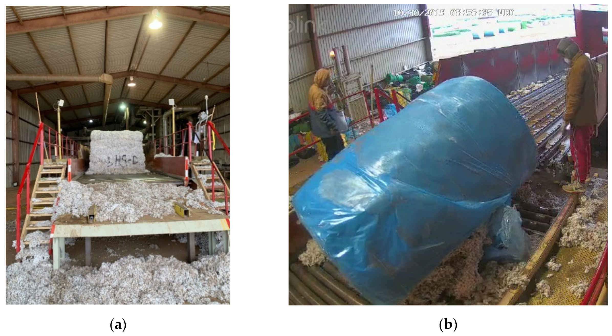
The removal of plastic contamination in cotton lint is an issue of top priority to the U.S. cotton industry. One of the main sources of plastic contamination showing up in marketable cotton bales, at the U.S. Department of Agriculture’s classing office, is plastic from the module wrap used to wrap cotton modules produced by the new John Deere round module harvesters. Despite diligent efforts by cotton ginning personnel to remove all plastic encountered during unwrapping of the seed cotton modules, plastic still finds a way into the cotton gin’s processing system. Plastic contamination in cotton is thought to be a major contributor to the loss of a $0.02 (U.S.)/kg premium that U.S. cotton used to command on the international market due to its reputation for one of the cleanest cottons in the world. Current data now shows U.S. cotton is trading at a $0.01(U.S.)/kg discount, relative to the market for a total loss of $0.034(U.S.)/kg with respect to market conditions prior to wide-spread adoption of plastic wrapped cotton modules. The cost of this loss to U.S. producers is in excess of $750 (U.S.) million annually. In order to help address this loss and mitigate plastic contamination at the cotton gin; an inspection system was developed that utilized low-cost color cameras to see plastic on the module feeder’s dispersing cylinders, that are normally hidden from view by the incoming feed of cotton modules. The research observed that in operation, one common source of plastic getting into the module feeder was during the unloading of module if it accidentally tipped over thereby trapping plastic underneath the module, Figure 1.
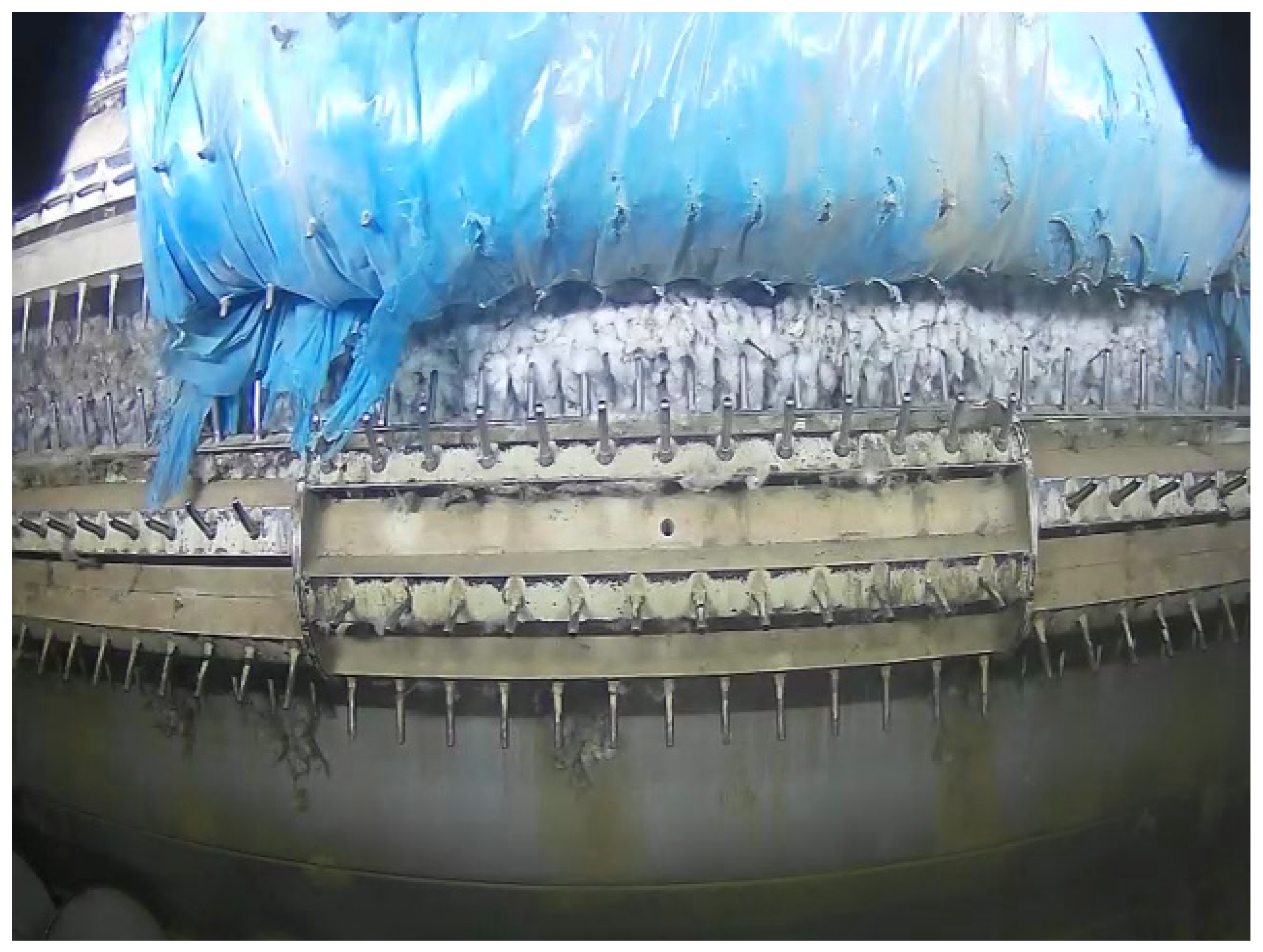
Which would invariably lead to large pieces of module wrap plastic from becoming entrained onto the module feeder dispersing cylinders, Figure 2.
During operation, when plastic builds up on the module feeder’s dispersing cylinders, it eventually tears off in small pieces scattering contamination across a large swatch of cotton.
This technical note presents the design of an automated intelligent machine-vision guided cotton module-feeder inspection system. The system includes a machine-learning program that automatically detects plastic contamination in order to alert the cotton gin personnel as to the presence of plastic contamination on the module feeder’s dispersing cylinders. The system was tested throughout the entire 2019 cotton ginning season at two commercial cotton gins and at one gin in the 2018 ginning season. This note describes the over-all system design, the mechanical and electrical design and provides an over-view and coverage of key relevant sections of the software design. Included as an attachment to this technical note are all the mechanical engineering design files as well as the source-code for the machine-vision system software and a complete bill-of-materials for fabrication and production of the system. Key design issues are discussed along the observational impact the system had on reduction of plastic contamination.
The system was designed with two main installation paradigms; a simple system, option 1, that would require very low technical expertise and the full system, option 2, that would provide a full feature approach, but would require more technical expertise on behalf of the cotton gin personnel. An overview of the two options are presented next and then followed up with detailed discussion of each system.
2. System Overview
2.1. Option 1 Overview: Simple Module Feeder Camera System
The first option, 1, is the simplest system that is comprised of:
- ●
- IP Cameras,
- ●
- Mechanical camera housing with integral optical air-wash to help keep optics clear of debris,
- ●
- Generic security camera viewing system provided by cotton gin.
2.2. Option 2 Overview: Automatic Stand-Alone Module Feeder Camera System [To Be Released Q4 2020]
Option 2 augments Option1, Simple System, by adding custom software that runs on a stand-along PC. The software augments the system by enabling the system to interact with a PLC to automatically pause the module feed, thereby providing enough time to allow for the cotton to settle out of the air enabling cameras after which the software automatically captures a clear picture of dispersing cylinders. When this development is finished, it will also include automatic detection of plastic on cylinders and provide an external relay to trigger an alarm beacon to alert the gin crew of the presence of plastic on the cylinders.
3. Mechanical and Optical System Details
3.1. Option 1 Details: Simple Module Feeder Camera System
The simple system is for the construction of a camera housing with integral air-wash, to keep the optics clean, to house ethernet IP cameras and suggestions as to suitable lights. This simplified system will use the cameras in their primary intended usage, i.e., in security camera viewing mode, and will depend upon the gin to provide or use the included software that comes with the cameras for viewing of the dispersing cylinders. This system provides a system that can be readily adopted by most gins with minimal technical expertise. The simplified version allows for inspection of module feeder rollers whenever the feed is stopped. Figure 1 shows an example image, taken during 2019 ginning season, from one of the cameras mounted on the back wall of a module feeder.
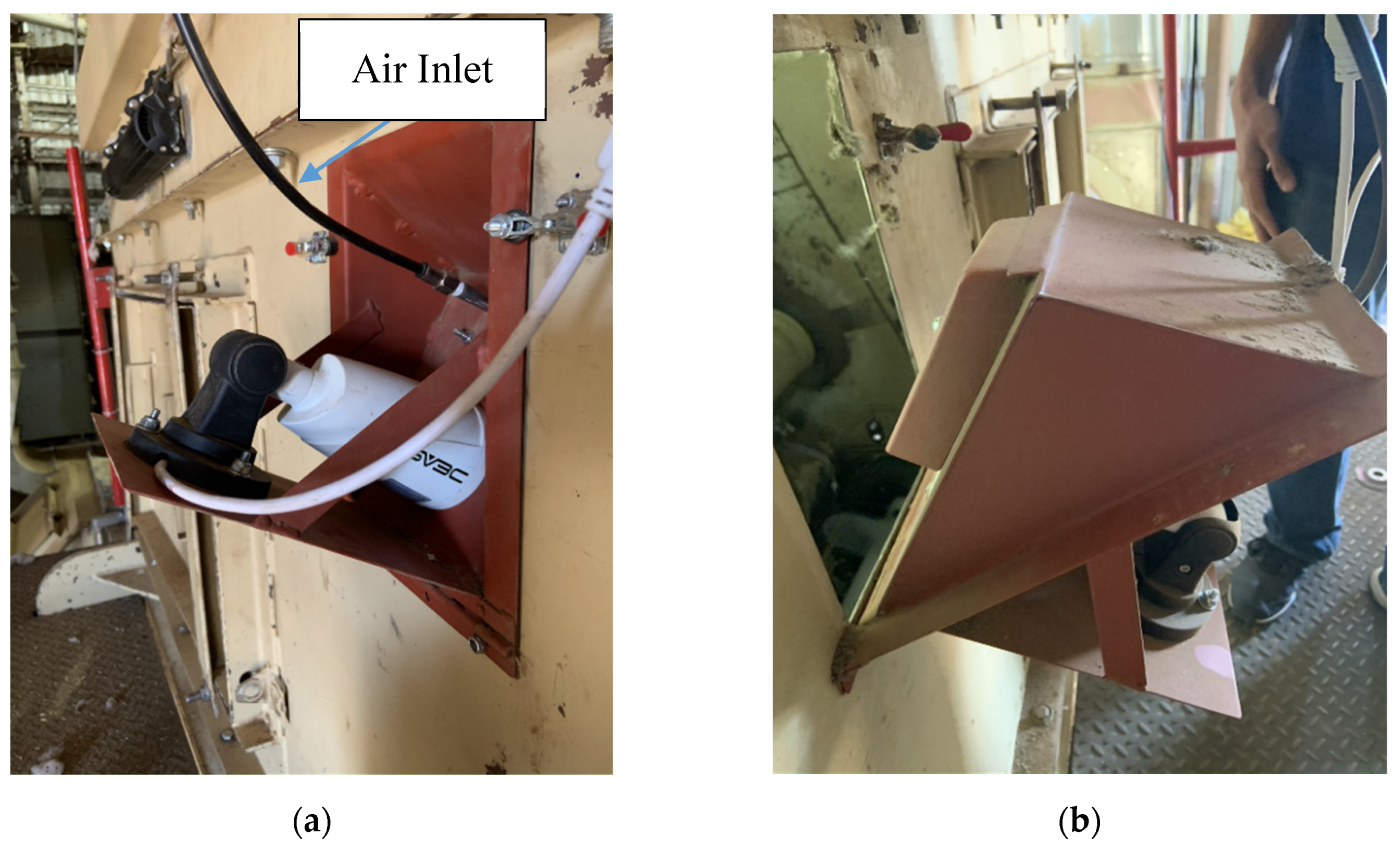
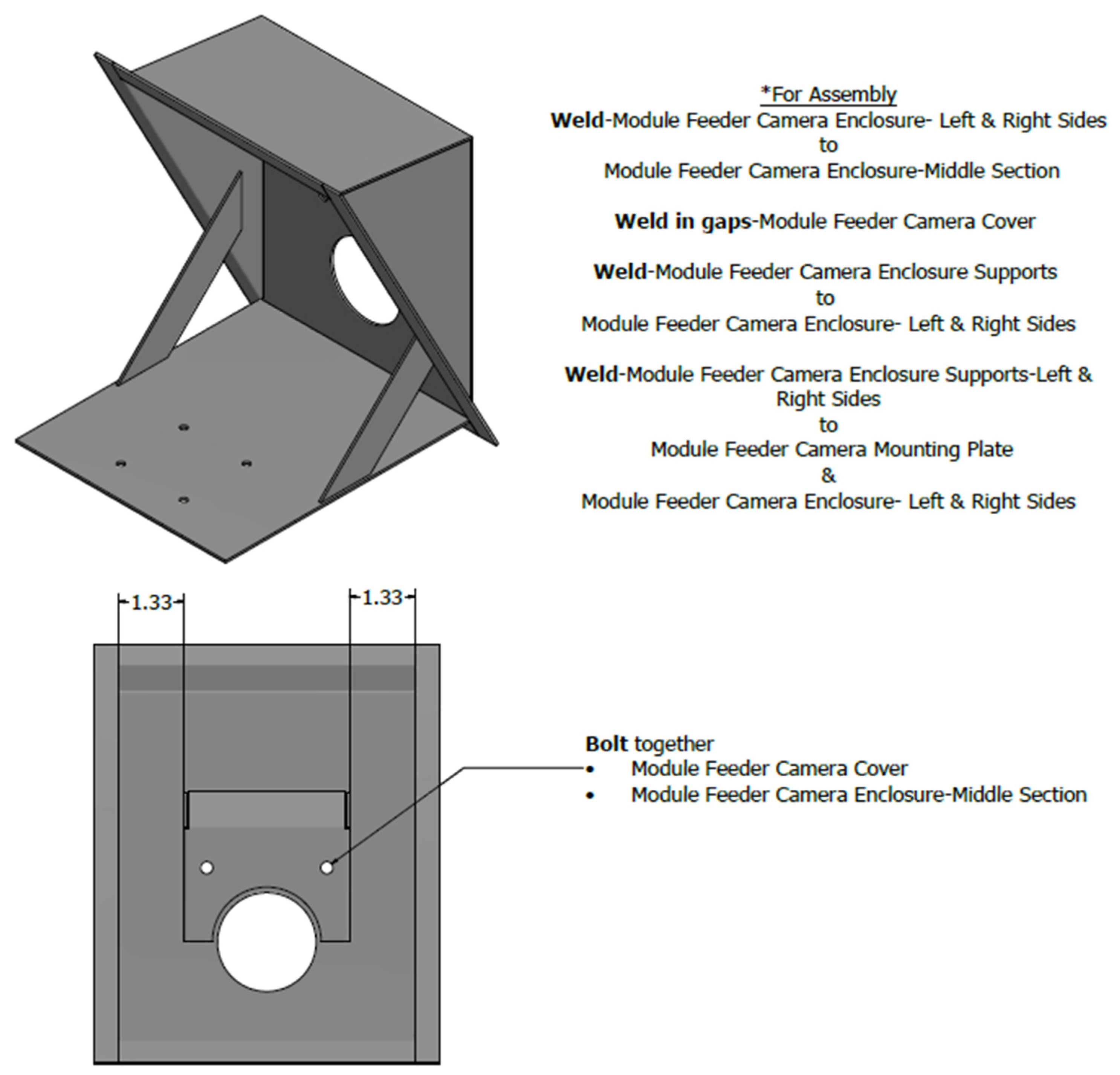
For this option, a custom housing design, with integral quick access for cleaning, is shown in Figure 3a. The mechanical fabrication design files for this housing are provided in the drawings package that are included with this technical note as an attachment. Of note, to provide easy cleaning, is the hinge that allows access to camera for periodic cleaning of the optics. Figure 3b, shows the housing tipped out for easy access to optics for cleaning.
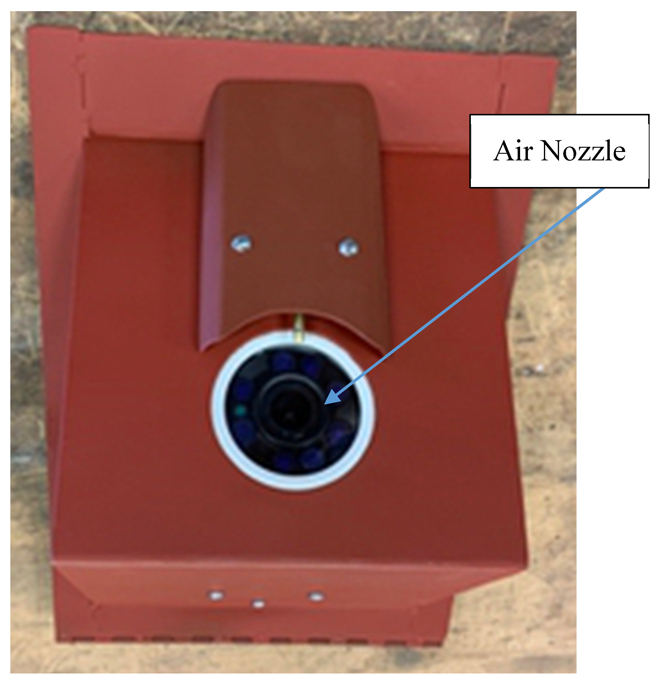
The air wash nozzle’s position is shown in Figure 4.
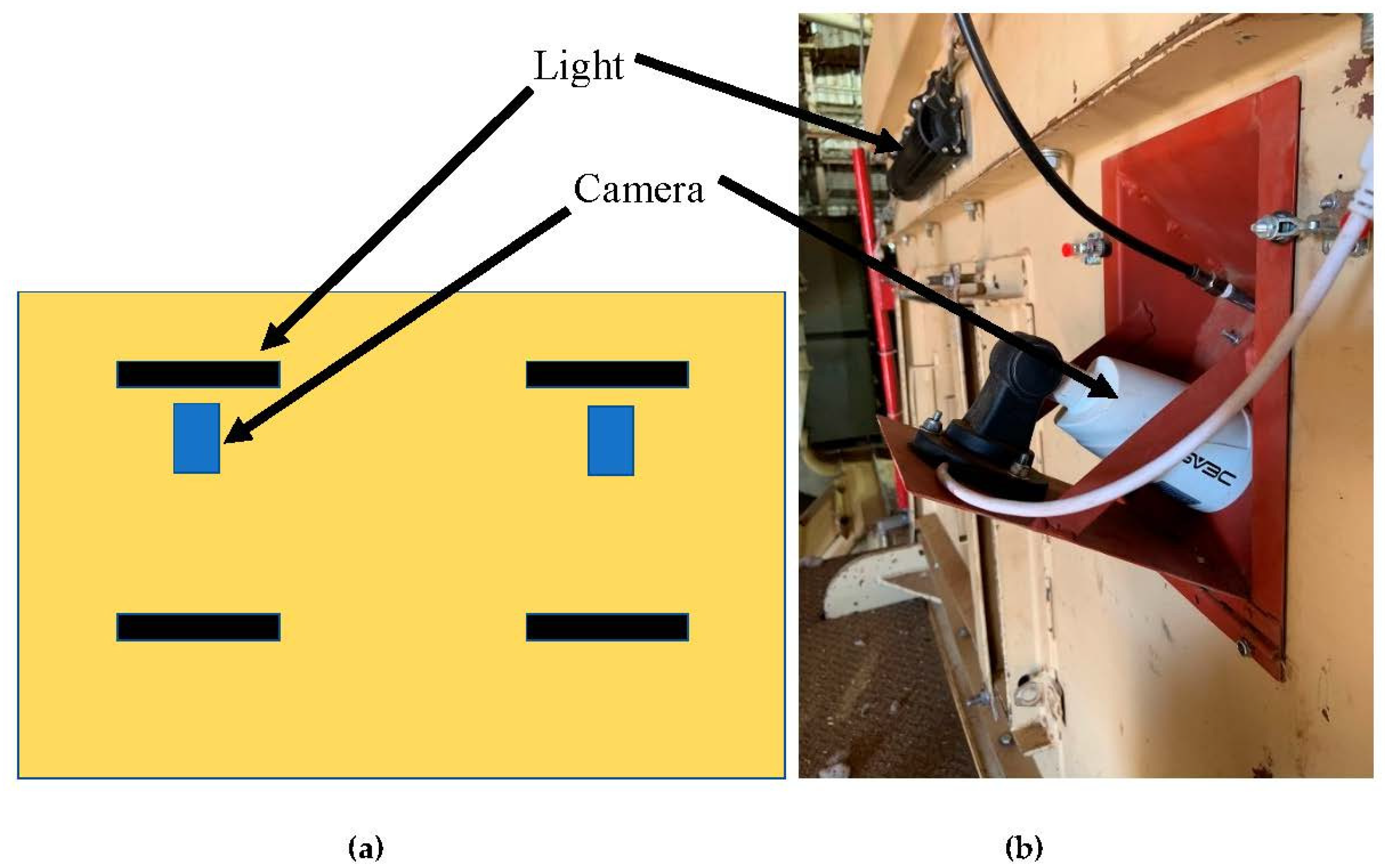
The recommended position of the camera housing and lights, on the back-wall of the module feeder, are shown in Figure 5. Another alternative camera light location to consider is the roof of the module feeder. As when placed on the ceiling, well back from the cylinders, this location provides ideal protection from flying debris.
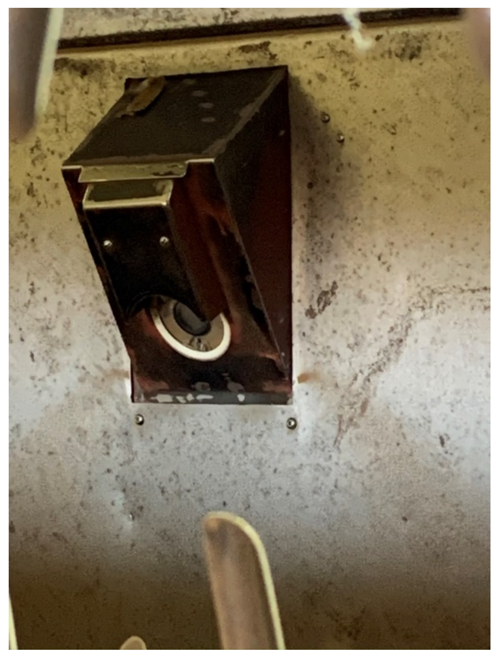
Figure 6 shows the camera housing as seen from inside the module feeder. For many module feeders, two cameras will be required to enable viewing of entire module feeder dispersing cylinders. For a few of the smaller feeders, a single camera might be acceptable.
Conversely, there might be a few module feeders with very close back walls, where the camera is mounted too close to view entire range from top to bottom cylinders, in which case 3 or 4 cameras might be necessary. Of importance is to note the sloping angle of the housing, which helps it shed cotton and debris. Along that same design paradigm, is the shroud covering the air-wash nozzle which helps to prevent cotton from hanging on the air nozzle. As the air-wash nozzle is pointed directly at the camera lens, it is important to provide filtration to pneumatic air supply to ensure a source of clean dry air to the air-wash system.
Of note is that for any one particular installation, the distance between the back wall to the dispersing cylinders will dictate required placement of the components. Best practice is to hook up the cameras and hold them on the inside, against the back wall, in approximate location and adjust until image coverage of dispersing cylinders is suitable. Depending upon the geometry of the particular module feeder, the angle that the housing positions the camera at may need to be adjusted before fabrication and/or may require more than one camera.
3.2. Option 2 Details: Automatic Stand-Alone Module Feeder Camera System
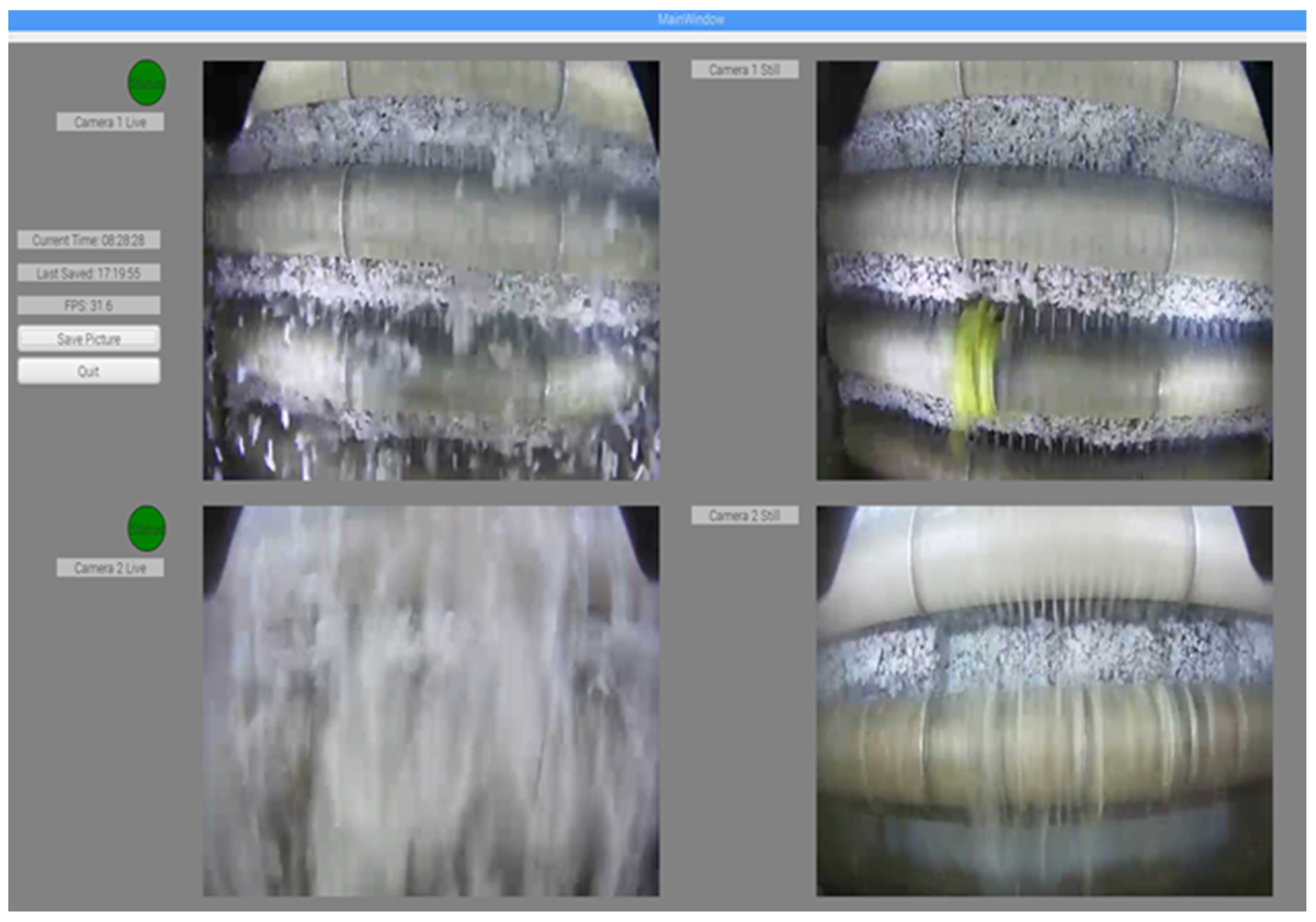
Option 2 augments the Simple System, Option 1, by adding custom software that can automatically schedule a pause in the module feed, thereby allowing a brief window for the cotton to settle out of the air long enough to capture a clear picture of dispersing cylinders. Figure 5, on left side live images, provides an example of what the view from the cameras is like when module feed is not stopped. The system provides user the benefit for automatic scheduled inspections of the module feeder’s dispersing cylinders. Suggested scheduling interval is every 10 min; however, the custom software allows the gin manager to select inspection intervals that best suit their gin’s operation. The custom software displays both the live-feed, from camera/s, as well as the latest captured still image (after snow-storm settles). Once development is completed, the software will also provide automatic detection of plastic on rollers and the following key features:
- Starting a timer to time how long plastic remained on rollers and log this information for later review by management,
- Provide an external relay interface that can be used to light up a detection indicator to alert gin crew that the module feeder has plastic in it and needs to be cleaned.
This option is designed to run on a single PC stationed at a key central operational point in the gin. The PC interfaces to the gin’s PLC via a dry contact ethernet switch that is used to trigger the PLC to pause the module feed.
3.3. Limitations
The system was designed around very low-cost ethernet IP cameras. They were tested with custom software in development for Option 2 and found to be suitable. The choice for very low cost cameras was made, as a design decision, in an effort to avoid protection windows as they can’t be plastic (as static would render them un-viewable) and the cameras already have glass windows so adding safety glass in front of cameras adds other engineering issues that were felt best avoided with option of low-cost disposable cameras. This concept was tested at 2 gins, in 2019 ginning season, and resulted in the loss of only one camera that was placed low on the back wall of one of the module feeders. The housing is specifically designed to enable quick access to camera lens for cleaning, in advent of wet weather and cotton where mud was found to be an issue. This concept was found to work well and is encouraged to include in the fabrication of similar units.
During the course of the prototype testing it was determined that mounting of cameras high up on the back wall of module feeder provided a safer location that required less maintenance and is the suggested installation practice.
LED power supply notes: (constant Voltage 12VDC) note: we had some issues with our last purchase of a similar LED power supply purchased from Amazon (330W) where the first set that were purchased were fine; however the second set were different and didn’t work at all (lights flickered, likely too much current draw for the power supply). Adopter may want to find a different source from 1000bulbs.com or similar.
4. Software Design and Implementation
The computer utilized for the basis of the design was based on a low-cost embedded cell-phone ARM processor. The computer interfaced to the cotton gins programmable-logic-controller, PLC, to pause the feed of the cotton periodically. The custom software display is shown in Figure 7. Details in the software implementation will be discussed in a follow up report.
5. Electrical System
The optional electrical interface to the PLC is a simple normally closed dry-contact switch that alerts the PLC to pause the floor when-ever the switch is opened. To allow for flexibility in placement of the switch, a low-cost ethernet based relay, included in BOM (Table 1 and Table 2), was selected and is controlled by the custom software. Another alternative, available via the software, is to allow the PLC to switch a relay (or a manual user), thereby providing a dry-contact to the system. Again, this more advanced system will be discussed in a follow-up paper.
6. Discussion: Impact of System on Plastic Contamination
After monitoring the prototype system during the 2019 ginning season, over 60 instances of plastic on dispersing cylinders were captured. As these large module tarp pieces can rapidly shred and tear off, these 60 instances have the potential to turn into 1000s of plastic contamination pieces by the time the make their way into a final cotton bale. A key observation was that the gin personnel was very attentive to the plastic, such that at every occurrence in the image data-set progression, there was almost never a time when the plastic was observed on more than one cycle. In essence, this means the gin crew was exceptionally dedicated to removing the plastic once it they observed it on the rollers. Another key finding from a design perspective, was that the top camera required significantly less maintenance than the bottom camera. The top camera was also much less likely to be damaged by rocks and less likely to be covered up by mud. Given this observation, our recommendation is to strive to avoid placing the cameras low. Of note however is that lights will likely still be needed on the lower section in order to provide enough light to illuminate the lower cylinders. As the plastic hangs more often on the lower cylinders, it is critically important to ensure the camera has full view of these lower dispersing cylinders. Best practice is to hand-position lights and verify sufficient lighting in images before cutting in mounting holes for lights. Nominal light levels at surface of dispersing cylinders were from 500–1000 Lux.
When the system was put into practice in a commercial cotton gin, the gin enjoyed a significant drop in the number of plastic calls after installation, and diligent use of the system, in comparison to the prior year when they had no inspection system. While only an observational single case study; it does suggest real benefits can be achieved when inspection systems are installed and used to rapidly identify when plastic gets onto the cotton module’s dispersing cylinders and the gin crew expediently removes the plastic before it has a chance to shred the plastic and disperse it further into the gin.
7. Mechanical Design Drawings
8. Module Feeder Parts List (Simplified-System)
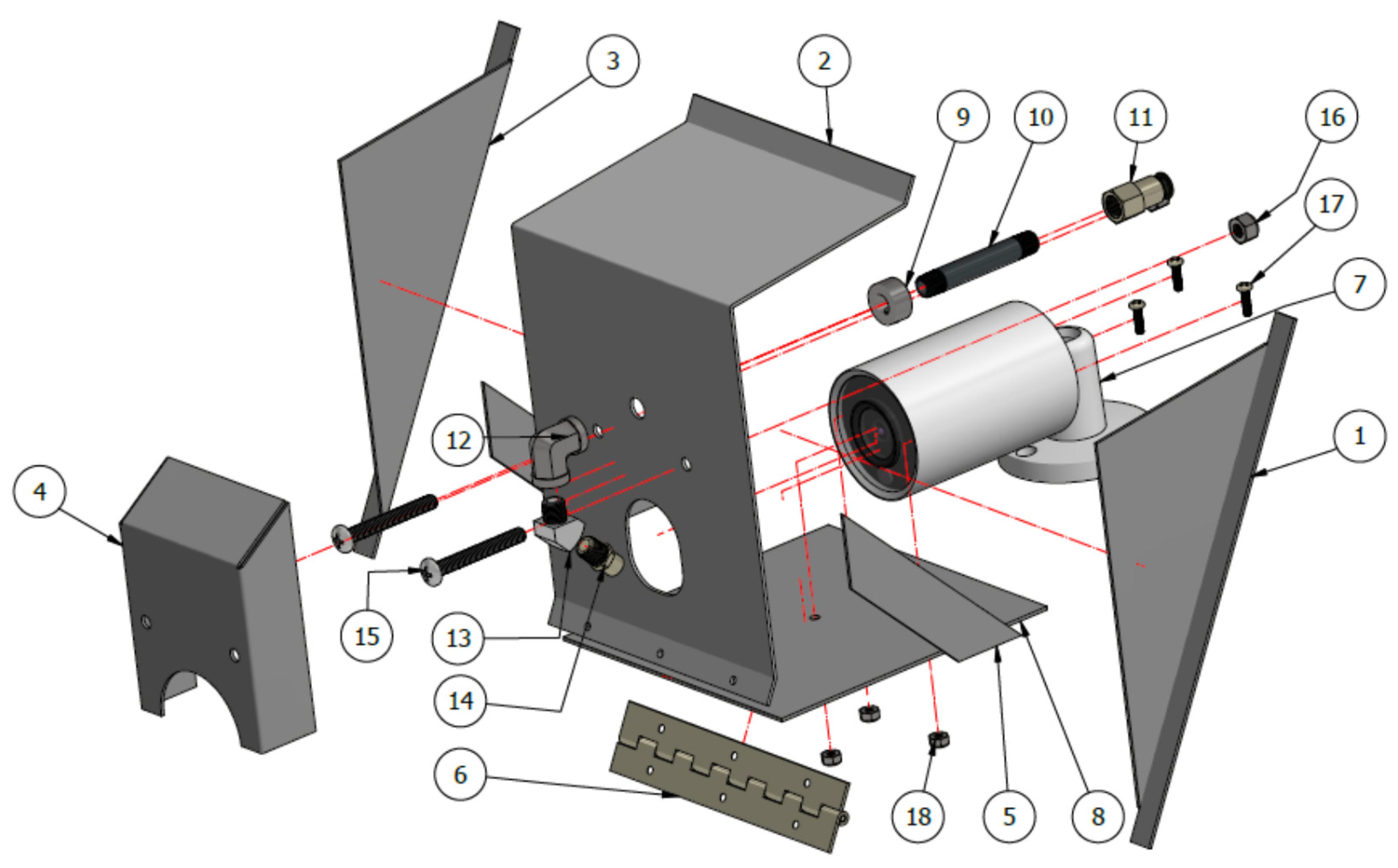
Module feeder parts list are shown in Table 1 and Table 2. Note that part assembly Id #’s refer back to full assembly drawing detailed in Figure 8, Figure 9, Figure 10, Figure 11, Figure 12, Figure 13 and Figure 14.
Miscellaneous parts:
- A UPS battery backup and industrial power filter
- Pneumatic filter to provide dry clean air to optical air-wash nozzle
License: All material and designs herein are donated to the public domain under a Creative-Commons Open-Source license.
Figure 1.
Module feeder floor system (a) and unloading of round module onto the module feeder floor (b) where the module accidentally tipped over trapping plastic underneath it. Whenever this situation occurred, the gin crew wasn’t always able to remove all of the plastic before it went on into the gin.

Figure 2.
Module feeder image capture by inspection system with plastic on dispersing cylinders.

Figure 3.
Second generation inspection camera and simplified housing, that relies on external lights. (a) shows the back side of the module feeder and (b) shows the housing as it’s tipped back out of the module feeder, allowing easy access to the optics for cleaning. Of note is the air-inlet tube, seen in Figure 2a, that directs air across the optics thereby providing an air-wash to help keep the optics clean.

Figure 4.
Shows the camera side of the air-inlet tube, back-side view is detailed in Figure 2a, that directs air across the optics thereby providing an air-wash to help keep the optics clean.
Figure 4.
Shows the camera side of the air-inlet tube, back-side view is detailed in Figure 2a, that directs air across the optics thereby providing an air-wash to help keep the optics clean.

Figure 5.
General placement (a), on back wall of module feeder, of camera inspection system components. Black boxes indicate placement of lights, blue boxes indicate placement of camera housings. Picture (b), shows how the camera and one of the lights were installed at a commercial gin.
Figure 5.
General placement (a), on back wall of module feeder, of camera inspection system components. Black boxes indicate placement of lights, blue boxes indicate placement of camera housings. Picture (b), shows how the camera and one of the lights were installed at a commercial gin.

Figure 6.
Camera housing as seen from inside the module feeder.

Figure 7.
Module feeder custom software (option 2: Schedule Release Q3 2020) where installation utilized two cameras (one top, one bottom). The left-side of display shows images that are of the live feed from the cameras. The right-side images are the captured images that were taken after the software paused the module feed, thereby allowing cotton to settle out of the air, providing a clear camera shot of the cylinders.

Figure 8.
Design drawing of module feeder camera housing (units in inches).

Figure 9.
Module feeder camera housing assembly drawing.

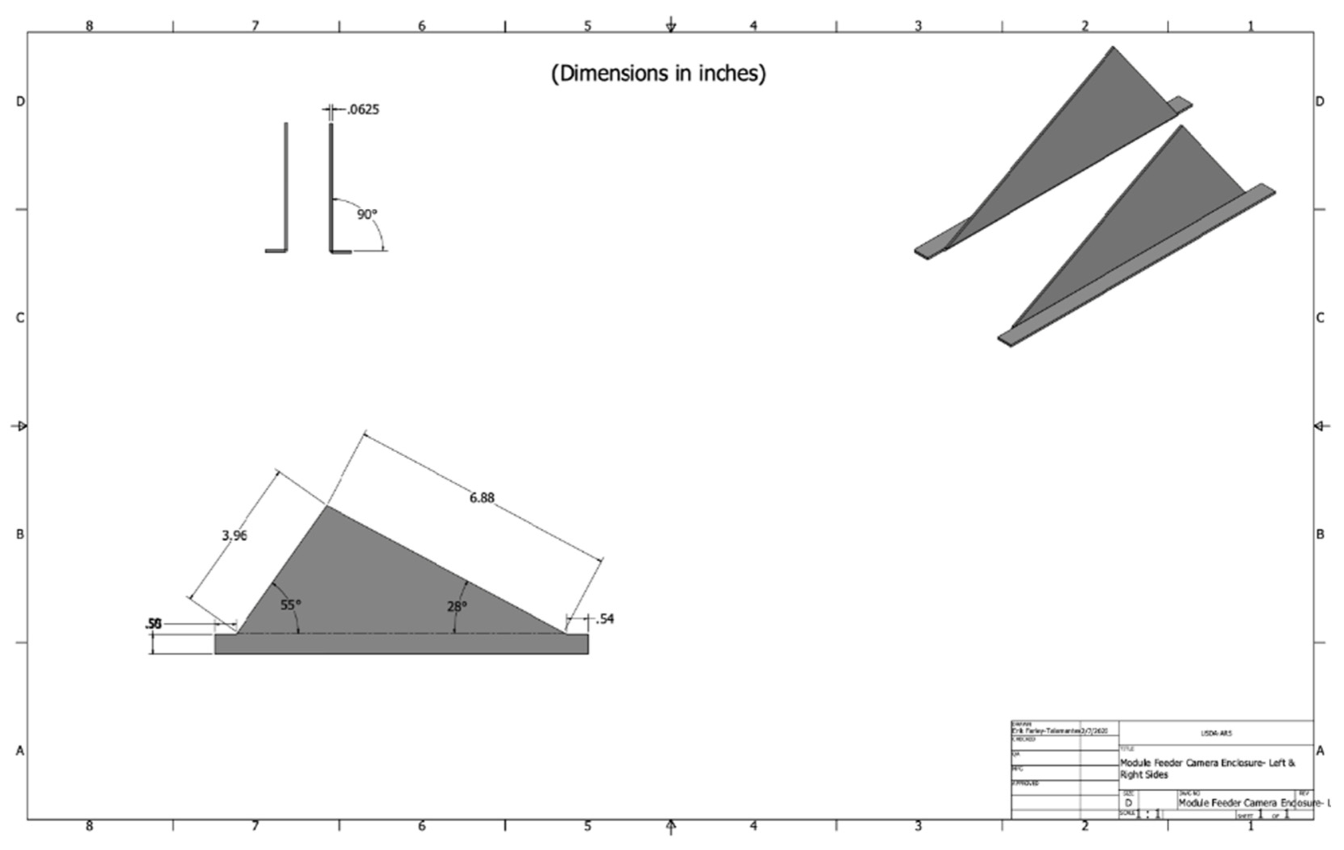
Figure 10.
Module feeder camera housing support bracket (#1, 3 of assembly drawing).

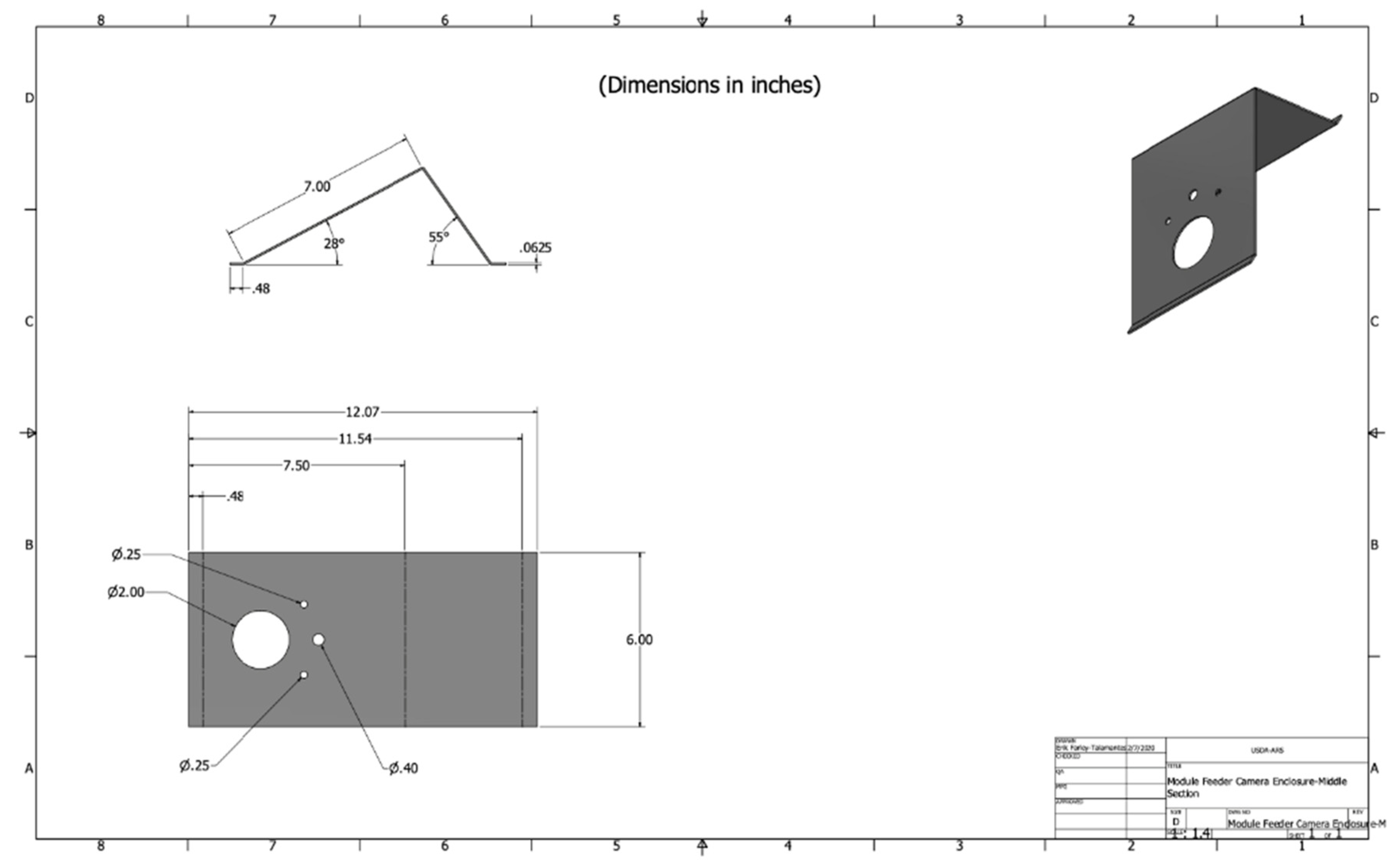
Figure 11.
Module feeder camera housing middle section (#2 of assembly drawing).

Figure 12.
Module feeder camera housing air-wash tube protection cover (#4 of assembly drawing).

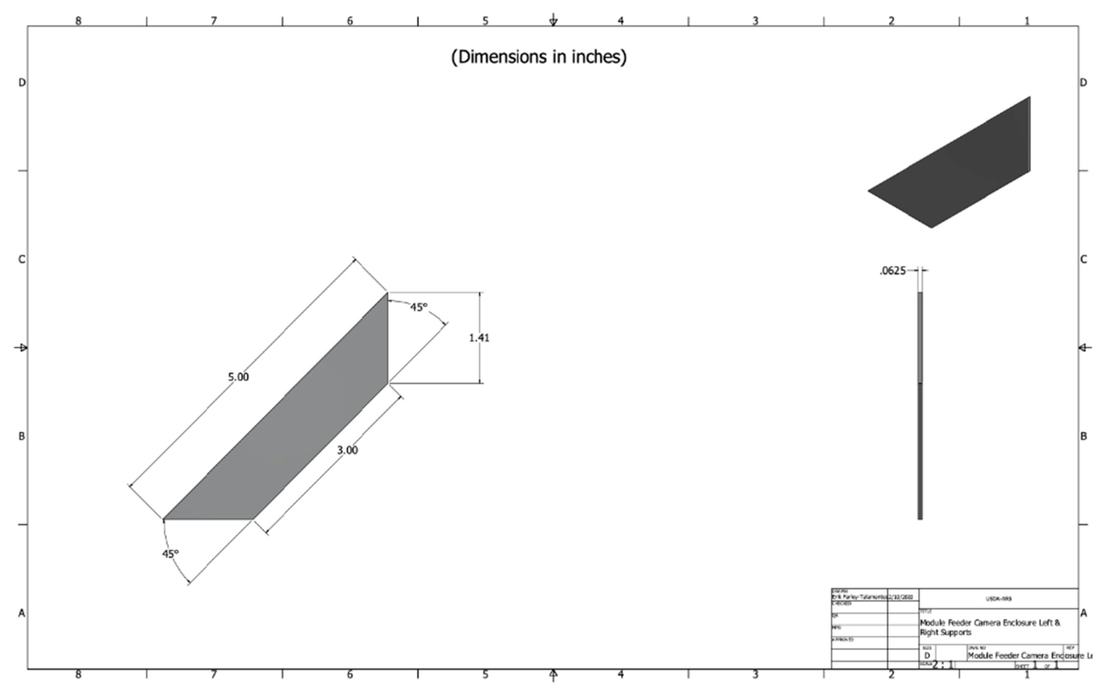
Figure 13.
Module feeder camera housing enclosure support straps (#5 of assembly drawing; x2).

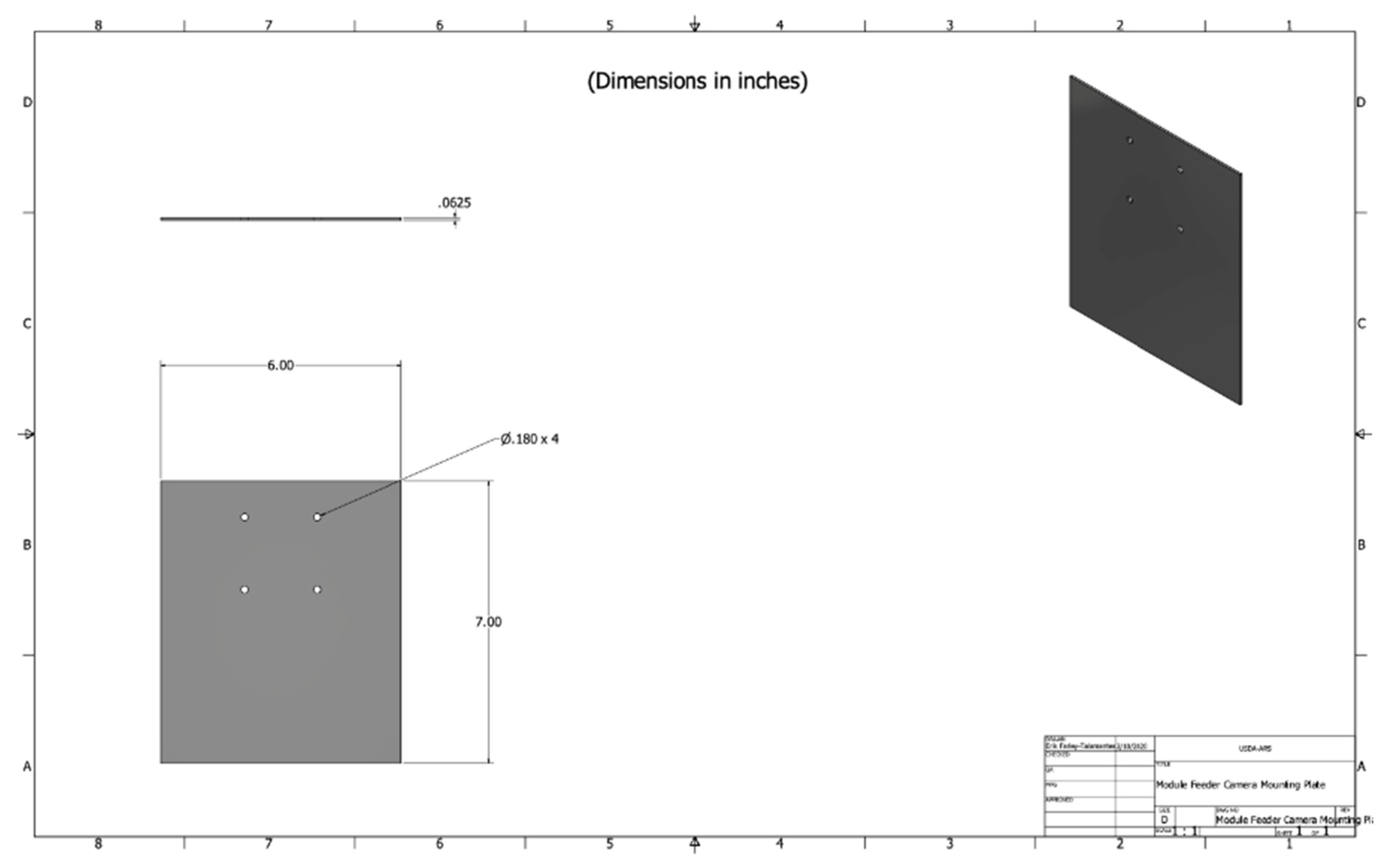
Figure 14.
Module feeder camera mounting plate (#8 of assembly drawing).


Table 1.
Bill Of Materials (Available from Amazon.com).
Table 1.
Bill Of Materials (Available from Amazon.com).
| Part ID, Picture | Product Description | Price |
|---|---|---|
 Part Assembly Id: 7 | Dahua Lite 4MP IP Mini-Bullet IR 2.8mm Security Camera (N41BD22). Power from 12VDC power supply or via POE switch | $125.31 |
 | LED Light Bar Nilight 20 Inch 126w LED Work Light Spot Flood Combo Led Bar Off Road Lights Driving Lights Led Fog Light Jeep Lights Boat Lighting. | 4 @ $25.92 |
 | Idealy 150W DC 12V Ip67 Waterproof LED Power Supply Driver Transformer Adapter for Lighting Strip with outdoor. | 4 @ $33.99 (1 per light) |
Table 2.
Bill of Materials (from McMaster Carr).
| Product Description | Product Link | Product ID | Price |
 Part Assembly Id: 14 | Full-Cone spray nozzle https://www.mcmaster.com/32885k131 | 32885K131 | $10.52 Each |
 Part Assembly Id: 9 | Set Screw Shaft Collar for 3/8′ Diameter, Black-Oxide 1215 Carbon Steel https://www.mcmaster.com/9414t8 | 9414T8 | $1.38 Each |
| Product Description | Product Link | Product ID | Price |
 Part Assembly Id: 12 | Standard-Wall Steel Pipe Nipple Threaded on Both Ends, 1/8 NPT, 2-1/2′ Long Compact Extreme-Pressure Steel Pipe Fitting 90 Degree Elbow Connector, 1/8 NPTF Female https://www.mcmaster.com/50925k118 | 50925K118 | 1@ $4.80 |
 Part Assembly Id: 13 | High-Pressure Brass Pipe Fitting 45 Degree Elbow Adapter, 1/8 NPT Female x Male https://www.mcmaster.com/50785k81 | 50785k81 | 1@ $3.53 |
  Part Assembly Id: 6 | Piano Hinge with Holes Steel, 1-1/4′ Overall Width, 0.245′ Knuckle Diameter (cut to 6′) https://www.mcmaster.com/1569a927-1569A391 | 1569A927 | 1@ $2.65 @ 1 ft length |
 Mounted externally to assembly on module feeder to hold housing in place, (Figure 4b) | Low-Profile Hold-Down Toggle Clamp https://www.mcmaster.com/5128a62 | 5128A62 | $10.07 Each x2 |
© 2020 by the authors. Licensee MDPI, Basel, Switzerland. This article is an open access article distributed under the terms and conditions of the Creative Commons Attribution (CC BY) license (http://creativecommons.org/licenses/by/4.0/).
Share and Cite
MDPI and ACS Style
Pelletier, M.G.; Holt, G.A.; Wanjura, J.D. A Cotton Module Feeder Plastic Contamination Inspection System. AgriEngineering 2020, 2, 280-293. https://0-doi-org.brum.beds.ac.uk/10.3390/agriengineering2020018
AMA Style
Pelletier MG, Holt GA, Wanjura JD. A Cotton Module Feeder Plastic Contamination Inspection System. AgriEngineering. 2020; 2(2):280-293. https://0-doi-org.brum.beds.ac.uk/10.3390/agriengineering2020018
Chicago/Turabian StylePelletier, Mathew G., Greg A. Holt, and John D. Wanjura. 2020. "A Cotton Module Feeder Plastic Contamination Inspection System" AgriEngineering 2, no. 2: 280-293. https://0-doi-org.brum.beds.ac.uk/10.3390/agriengineering2020018