
Development of a Wireless System to Control a Trombe Wall for Poultry Brooding


1
ECT—School of Sciences and Technologies, UTAD—University of Trás-os-Montes and Alto Douro, 5001-801 Vila Real, Portugal
2
CQ-VR—Center of Chemistry of Vila Real, University of Trás-os-Montes e Alto Douro, 5000-801 Vila Real, Portugal
3
CRIIS—Centre for Robotics in Industry and Intelligent Systems, Technology and Science, INESC-TEC—Institute for Systems and Computer Engineering, 4200-465 Porto, Portugal
*
Author to whom correspondence should be addressed.
AgriEngineering 2021, 3(4), 853-867; https://0-doi-org.brum.beds.ac.uk/10.3390/agriengineering3040054
Submission received: 30 September 2021
/
Revised: 19 October 2021
/
Accepted: 25 October 2021
/
Published: 29 October 2021
(This article belongs to the Special Issue IoT in Agriculture)
Abstract
:The Internet of Things asserts that several applications, such as smart cities or intelligent agriculture, can be based on various embedded systems programmed to do different tasks, by transferring data over a network from sensors to a server, where the information is stored and treated, supporting the decision-making process. In this context, LoRaWAN is an accurate network topology based on a wireless technology called LoRa that is capable of transmitting small data rates at a long range, using low-powered devices, making it ideal for the acquisition of climate variables, such as temperature and relative humidity. Applying this architecture to agriculture buildings can be very useful to guarantee indoor thermal comfort conditions. In this study, this technology is applied to a passive solar system composed by a high thermal inertia wall, defined as Trombe wall, with air vents provided in the massive wall to improve heat transfer by air convection, and an external shading device to avoid overheating during summer and heat losses during winter. It is intended to analyze the possibility to control the interiortemperature of a poultry brooding house given that, in the early stages of life, chickens need accurate climate conditions in order to enhance their growth and reduce their mortality rate. In brief, temperature values acquired by different sensors placed on the Trombe wall travel through a LoRaWAN wireless network and are received by an application that controls the actuators, in this case, the opening and closing of the Trombe wall air vents, while the external shading device is controlled locally.
1. Introduction
A brooding house is a building that simulates the growth of chickens without their progenitor, from the day of the hatch to an age of about four weeks. Water, food and warmth are the most important factors during this stage in order to make them healthy and increase their development. This brooding house tries to replicate the temperature conditions that characterizes the time when chickens are under the mother’s care. Some studies state that the maximum temperature for this type of brooding is 35 °C [1,2]. It is very important to control these factors during these stages of the bird’s life, given that it is when a higher number of deaths is registered comparing with the rest of the chicken’s life stages. Balanced temperatures are a huge component to consider in order to regulate the mortality rate and the corporal and physiological development of the chickens [1,3].
Several systems can be used to maintain the required temperature comfort in these buildings. In some countries, poultry farmers use kerosene stoves to deliver heating to the brooding houses. However, this has its downsides: the kerosene is highly expensive, can easily result in a fire, and burning it results in the release of carbon monoxide (CO) and carbon dioxide (CO2), which are environmental pollutants. Some farmers also try to use the electrical grid to heat up the environment where chickens are; however, the system is expensive, not everyone has access to it, and there could be power outages, which makes the system unreliable. Both methods result in a high mortality rate and therefore a low production level. Consequently, these methods induced a production expansion to comply with the society needs, leading to environmental and socioeconomic problems [3].
There is the urge to develop an alternative method in order to maintain productivity by reducing death mortality. It should exist in abundance and be more reliable and environmental friendly. Taking into account these requirements, some improvements can be applied in building construction to make them more efficient and sustainable. The use of renewable energy, such as solar energy, can be a suitable solution [1]. The use of passive solar techniques, such as materials with high heat storage capacity, can be an option. Some studies show the use of a water tank located on top of the building, sensible to solar heating, that would easily diffuse that warmth to the brooding. However, this system can compromise the building structure and therefore would not be a suitable solution. Taking into account the disadvantages of those solutions, the use of a Trombe wall system was presented as an efficient one in some studies developed in this field [1,2,3,4].
A Trombe wall is a high thermal inertia wall that presents a great capability of storing heat and gradually releasing it to the environment. The system is composed by a massive wall with air vents and a glazing outside separated by an air gap, leading to a greenhouse effect that improves the wall heat storage capacity. The solar radiation is received by the wall through the glazing and then converted into heat, which can be more quickly or slowly transferred into the brooding house, depending on whether the air vents are open or closed. When the air vents of the massive wall are closed with XPS boards (nonventilated Trombe wall), the stored heat is gradually released through the massive wall by radiation, conduction and convection. When the air vents are open, an increase in heat transfer is obtained by air convection through the ventilation system (ventilated Trombe wall) [5,6,7]. These vents allow for the air circulation between the wall and the glazing to the chicken brooding house. Trombe wall has an excellent thermal conductivity that allows for the reduction of temperature fluctuations inside of the poultry brooding house [3,8].
The purpose of this work is to control the opening and closing of the massive wall air vents in order to maintain optimal and less fluctuated temperatures inside the brooding house. In order to achieve this objective, air vents are controlled with servo motors, based on the analyzed temperature values at an instant moment. These actions are made by a microcontroller along with a server in the Internet, so that the decisions of closing and opening the air vents are not made locally, avoiding user´s intervention.
There are some wireless systems that are normally used in building automation. WiFi, for example, is a consistent system that allows high data rates, but on the other hand, it consumes plenty of power when compared to others and has a short range. However, its suitability is verified when installed in homes, given that, nowadays, a WiFi router is commonly used. ZigBee is also considered a good wireless communication system because it is low powered and characterized by low implementation costs. In fact, it presents a similar range as WiFi but smaller data rates. As ZigBee, there is a similar system called LoRa, which is also a low-powered and low-data-rate wireless technology. However, it can reach further distances [9,10], which is an advantage in the case of its implementation over long distances. Given that the locations of poultry brooding houses are normally in large fields, WiFi and ZigBee might not be able to reach them; therefore, LoRa is considered the most suitable technology for these cases where temperature values registered by sensors are sent over a network. Furthermore, relatively small data packets are used; therefore, high data rates are not needed.
The microcontroller used in this system is an end-node of a star topology LoRaWAN network, in order to be connected to a server called The Things Network (TTN) and to guarantee its ThingSpeak integration on the application layer. Data registered by the temperature sensors travels from the microcontroller to the application where it is plotted. A decision is made based on data analysis and sent as feedback to the microcontroller. That decision contains information that tells the microcontroller to operate the actuators, which in this case are the servos controlling the air vents. The main goal of this research work is to make a decision in the Internet, using a server, given that a remote interaction with the system can be achieved [11].
1.1. LoRa
LoRa is a modulation technique in a wireless transmitting technology where an emitter sends small data packets at a low power (between 0.25 and 50 Kbps, in Europe) to a long-range receiver, as seen in Table 1 [12,13]. In one line of sight, there was once a record of 766 km [14]. This technology was developed by Cycleo, lately acquired by Semtech [15].
Essentially, LoRa is a way of operating radio waves to code information in a symbol format and an astute method of having good receiver sensitivity with a low bit error rate, in a long range [15,16].
In Europe, the modulation and the frequency band transmission belongs to the ISM (Industrial Scientific Medical, used to scientific means, industrial and medic ones that are not telecommunications) and is an open band, meaning that no license is required for its use. However, that creates disadvantages because there are more interference and low data rates [17]. Center propagation frequency is located between 863 and 870 MHz, and there are bandwidths of 125, 250 and 500 KHz to the information. Divided in 10 channels, eight of them diversify their data rates from 250 bps to 5.5 Kbps, one with 11 Kbps and another FSK channel working at 50 Kbps [12].
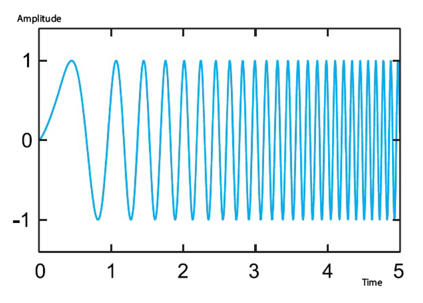
The modulation technique is called Chirp Spread Spectrum (CSS) and consists of the deliberate lengthening in frequency domain, obtaining more robust signals in the presence of noise, interference or jamming, thereby providing a basic reliability, whereas there is a higher safety when it comes to third parties interpretation of the signal. In exchange, there is an increase in bandwidth and a higher circuit complexity. These deliberate lengthening in the frequency spectrum have the designation of down-chirps (when frequency decreases over time) and up-chirps (when frequency increases over time), as seen in Figure 1 [18].
The Spreading Factor (SF) is the number of bits that can be encoded in a symbol and it can vary between 7 and 12. The higher this value, the greater the transmission range is, and consequently, the smaller the duration of the emitter’s battery, which is suitable to the range/battery. In brief, the bigger this parameter, the lower the data, rate and hence, the greater the time on air, making the range larger. This can be observed in Table 2 which represents an 11 byte packet being submitted to different SF values [19].
1.2. LoRaWAN
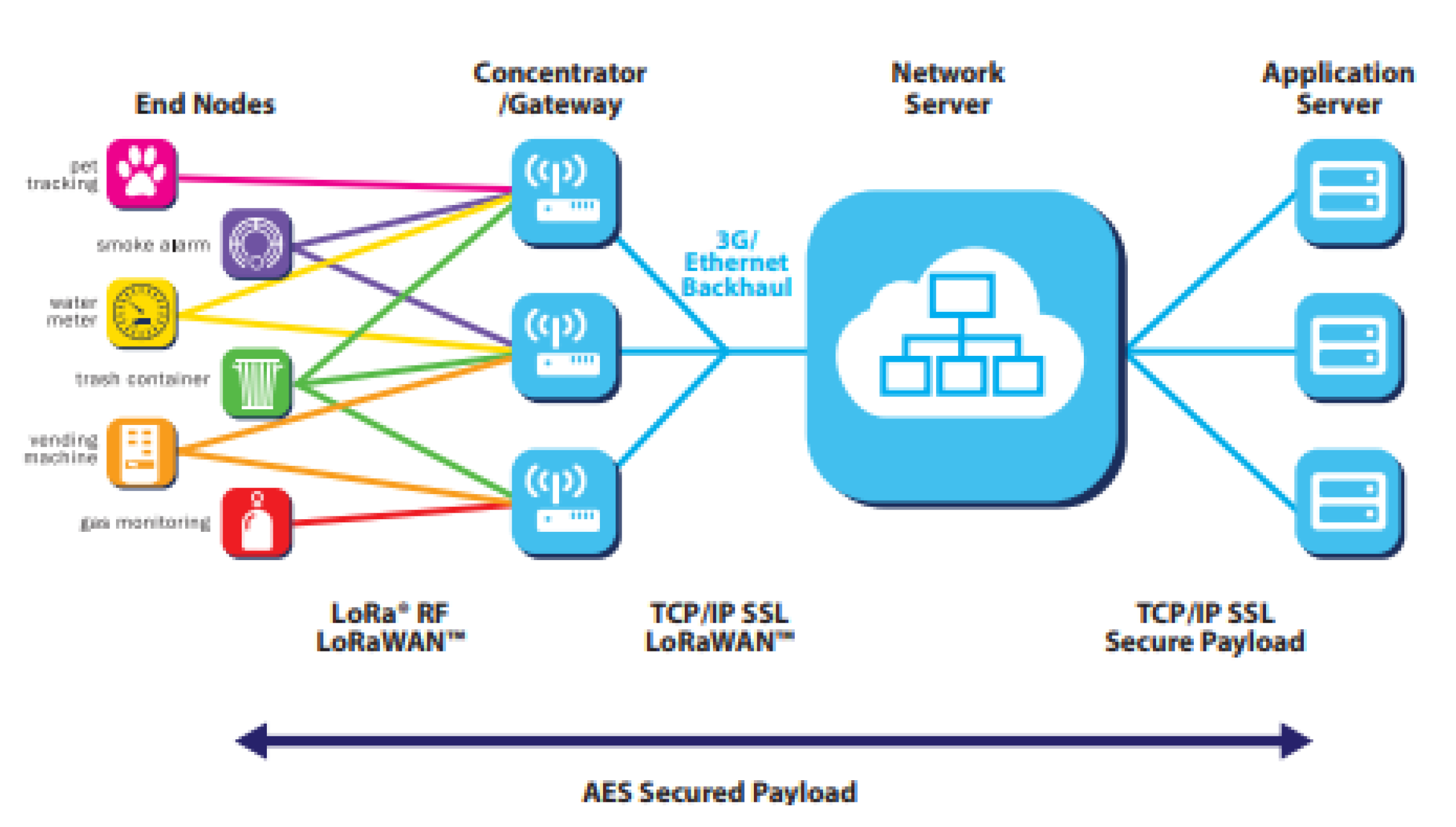
LoRaWAN is a medium-access control protocol built based on the LoRa modulation and is responsible by addressing the devices in order to realize a bidirectional communication between each other. It has a star network topology that can be seen in Figure 2. Its operation consists of the broadcast of generated values from several end-nodes to central gateways (using LoRa), those which transmit that information to a server, using another protocol, which filters, corrects the data and delivers it to the application layer. As everything is bidirectional, if required, the application can answer the server, where it is ascertained from which end-node the information came in order to transfer this response to it. However, communications between end-nodes are not allowed by this protocol [12,20].
The maximum packet size vary with the distributed values of data rates, consequently of the SF and of the bandwidth. Thereby, the size is [22]:
- To lower data rates (SF10, SF11 and SF12 using 125 KHz), the maximum packet size is 51 bytes.
- To medium data rates (SF9 using 125 KHz), the maximum packet size is 225 bytes.
- To higher data rates (SF7 and SF8 using 125 KHz), the maximum packet size is 222 bytes.
According to Figure 2, the topology is divided into the following elements:
- End-node: an end-node consists of a radio module and an antenna to receive/transmit data in a binary format, along with a microprocessor to process them [23]. There are three types of end-nodes [12]:
- − Class A: devices that when send a message to the server open two windows in order to receive a possible response (each window is approximately 20 s [24]). These are the most efficient on an energy level.
- − Class B: are what class A decides; however, these also open receiving windows that can be scheduled by the user.
- − Class C: these devices are always waiting for a response, unless they are transmitting; therefore, they are less efficient on an energy level.
- Gateway: This section works as a translator between the two network topology used. A gateway consists of a radio module and an antenna to receive/transmit data in a binary format, along with a microprocessor to process them, similar to an end-node [23]. However, these are designed to receive data from end-nodes in order to send them to a server in the Internet using another protocol (Ethernet, 3G or WiFi) and vice versa. From the same end-node, more than one gateway can receive the data. According to the literature, one only gateway can receive data from more than one end-node at different frequencies simultaneously [25].
- Server: There are a lot of servers that are willing to cooperate with LoRaWAN (LORIOT, ChirpStack and The Things Network). In this work, it is used The Things Network (TTN) that is an open-source infrastructure developed specifically to be an interface between LoRa devices and the application layer, endowed with robust encryption making it safe to use Internet of Things functions [26].
- Application: As servers, there are a lot of applications ready to be connected to a LoRaWAN network. In this case and as it fits the purpose, it is used the ThingSpeak integration and its applications React and ThingHTTP, that combined respond to a particular situation.
2. Materials and Methods
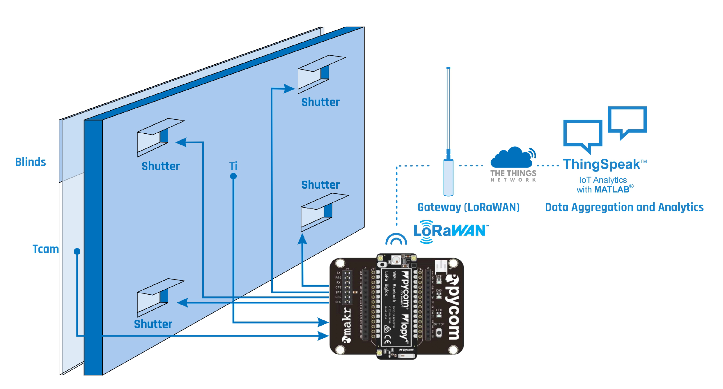
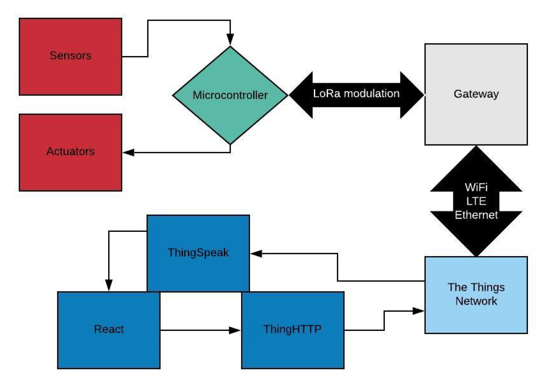
It is intended to implement a class A LoRa device in order to collect data from temperature sensors located in the Trombe Wall and send them to The Things Network platform, which acts as a server. There, they are transferred to the ThingSpeak integration and with the associated applications, which are be generated a response that are be sent to the microcontroller, based on the these work in the following way: if a received temperature value is higher, equal to or lower than a predefined value on React, this triggers a temperature value (Figure 3). These applications are React and ThingHTTP (this last one has to be an integration in The Things Network in order to let the data arrive at the server from ThingSpeak) and prefigured action [27]. In this case, that action is the ThingHTTP using the POST method to publish in the TTN server a response that fits the situation, which schedules the deliver of that feedback to the microcontroller, which acts on the actuators (XPS boards) [28]. Figure 4 is a block diagram that represents the whole system, step by step.
The Trombe wall system used for poultry brooding is based on the one studied in previous research works [5,6,7]. An automation and control system of the air vents and external shading device operating modes was also proposed to improve the Trombe wall thermal performance and guarantee specific indoor temperature conditions, without user´s intervention on the system management. Data acquired in this experimental study were analyzed and used as a support of the work here presented. The mechanical system defined in the referred work to perform the automation and control of the air vents was also considered [8]. However, this control system makes decisions locally, while the one designed in the presented work communicates with a server where those measures are taken. This is an advantage given the possibility to interfere on decisions and consult data remotely. As normally in this circumstances, the poultry structure is not in the range of WiFi; therefore, LoRa is used to communicate with a gateway, which redirects data via Ethernet to the server and vice versa.
The mechanical system defined in [8] allows the indoor temperature fluctuation control with the opening/closing of the ventilation system throughout the use of covering boards made by extruded polystyrene (XPS)—defined as shutters in Figure 3—with rotating hinges controlled by servos. XPS was used given its lightweight and thermal properties that contribute to avoiding heat transfer through the air vents. It also contributes to an easy movement of the mechanical system. The chosen servos were the “Futaba S3003” to the rotating system and the DHT21 sensors to the temperature measures. At the time of the achievement of the experimental study and based on research work developed by Yanfeng Liu [29], it was defined that a maximum advantage of the Trombe wall can be achieved based on the temperature differential between the air gap and the internal environment. This is made to maximize heat accumulation in the air gap before opening the XPS boards, allowing faster heat transfer to the internal space under study. In a previous research work, different scenarios were studied to optimize the temperature range values that support the working algorithm of the automation and control system. Different iterations led to the conclusion that the most suitable way to reach the indoor comfort temperatures would be to consider the temperature range between the internal environment (Ti) and the air gap (Tcam).The limit values established for the opening/closing of the air vents were considered effective for increasing the air gap greenhouse effect and heat storage before the opening of the air vents, so that the room would be heated more quickly and higher temperatures can be achieved. If that difference is higher than 15 °C, the air vents should be opened and if it is lower than 10 °C, they should be closed [8], as seen in Table 4.
To connect a device to the server, it is needed to access the TTN and create an account and an application. Then, it is necessary to register the device with its Device EUI, which is an unique code codified in the LoRa module, accessible throughout the microcontroller being used. EUI means Extended Unique Identifier, and it is a 64 bit value used as a component identifier, similar to a MAC address. After achieving both the previous steps, AppEUI and AppKey, which are authentication parameters used in the implemented function, are generated. The AppEUI identifies the server and is similar to a port number, while the AppKey is an AES key (Advanced Encryption Standard) with 128 bits used to ensure the message integrity. Both the server and the device need to share this key [30,31,32].
To be able to consult and act over the data received on the server side, ThingSpeak was used in the present research work, based on a platform analysis focused on the Internet of Things that allows one to collect data, analyze them and trigger a reaction. Data received by the TTN are plotted and analyzed in order to make a decision if the data correspond (or not) to the expected reference. Thus, inside ThingSpeak, two applications to make those decisions are used:
- React: It has the purpose of making a reaction to a predefined event in an attributed graph. In this specific situation, the required value is compared with the one that was received, and if it is equal, higher or lower, an action is taken. In the ThingSpeak, a React can be created and its specific characteristics can be defined [27].
- ThingHTTP: It is an application that allows the connection to a web service using the HTTP protocol throughout a network. It can use the normal requesting methods such as GET, POST, PUT and DELETE [33]. It can be integrated with React, creating a new requisition, assigning a downlink URL from the TTN that automatically redirects the information declared to the microcontroller. This information must have a JSON format and an adequate syntax in order to be interpreted by the TTN [28].
The microcontroller’s connection to the network is made by sockets. Socket is the extreme point of the provided service by the transport layer to the bidirectional communication between processes or applications. The connection to the server consists in the Over-The-Air Activation method (OTAA) and is the elected strategy, given that it provides a more secure connection when compared to other methods [34]. As referred previously, the server must know the device’s DevEUI, and the end-node must have knowledge of the server’s AppEUI, while both share the same AppKey.
In order to obtain the required results during the production process, in addition to a suitable indoor environment temperature, chickens must be continuously fed, and adequate amounts of water should be given daily. They should also be monitored by veterinary staff at least to prevent them from having diseases. Average body weight gain and the consumed food should be measured as well as the feed conversion ratio; therefore, the results can be compared to other brooding with another heating system (or without) [3].
2.1. Prototype
In this section, the applied wireless system that is controlling the Trombe wall operating modes is presented. The different stages to the prototype implementation at the practical level are described in detail. A setup approach is performed in a physical way as well as the execution at the application/server level.
The control is carried out using a LoPy4 from Pycom, which is a MicroPython, having embedded a software compiler of a programming language compatible with Python 3, written in C, and optimized to be executed in a microcontroller. It is equipped with 4 network protocols: WiFi, Bluetooth, Sigfox and LoRa. The last one is used to the practical development [35]. According to the component datasheet, it has a 3.3 to 5.5 V power supply and, when communicating via LoRa, draws approximately 15 mA (depending on data rates), while in standby consumes about 0.2 uA and at most 1 uA [35]. The used gateway is the one manufactured by The Things Network [36].
2.1.1. Connection to The Things Network
Right after creating an account, it is necessary to know the Device EUI so an application can be created. The EUI is the unique identifier in the LoRaWAN network associated to the device to get it registered.
Data rate was defined as 5 in the microcontroller in order to have a Spreading Factor of 7 and utilize a bandwidth of 125 KHz, as seen in Table 1 and Table 3. Given that the gateway in this test is less than 2 km away and it intended to maximize energy efficiency in the system implementation, lower data rates should be used, according to the desired transmission packet size.
2.1.2. Treating, Sending and Receiving Data
The DHT21 library referenced in [37] converts the collected temperature values into float, which is then converted into bytes, multiplying by 100 and dividing by 256: the integer value of the result is the “msb” (most significant byte), and the rest is the “lsb” (less significant byte). This means that each measure from each sensor requires two bytes to be sent in each packet. In order to address and forward the information, the send function is used in the previously opened socket that binds to The Things Network server that delivers each of the two byte measurements from the deployed sensors. As seen in the following code, before sending these bytes, the socket should be in blocking mode: meaning that the program does not proceed until the requested call is completed. Once the operation has ended, the socket should be set to a nonblocking mode.
import socket
s.bind(1)
s.setblocking(True)
s.send(bytes([HUMcam_msb, HUMcam_lsb, TMPcam_msb,
TMPcam_lsb, HUMi_msb, HUMi_lsb,
TMPi_msb, TMPi_lsb]))
s.setblocking(False)
receive()
In TTN, a decoder is written in Javascript, which receives the corresponding bytes where the information was carried and puts them in their original structure, in order to obtain the original values read by the sensors. The ThingSpeak integration is active from the moment when a value is given to a variable where the read numbers by the sensors are allocated to fields (in this case, field 3 to the temperature and field 4 to the humidity). The TTN immediately sends it to the application and plots it in the corresponding field. As can be seen in the following portion of the code, the bytes sent from the microcontroller are organized in the server side and are transformed into the original values. Once this step is completed, the values are assigned to fields, which constitute the information that is displayed on ThingSpeak side.
var decoded = {};
if (port === 1) {
decoded.HUMcam = (((bytes[0] << 8 |
bytes[1]) / 100).toFixed(2));
if (bytes[2] & 0x80){
decoded.TMPcam = ((((bytes[2] << 8 |
bytes[3])-65536) / 100).toFixed(2));
} else {
decoded.TMPcam = (((bytes[2] << 8 |
bytes[3]) / 100).toFixed(2));
}
return{
field3:decoded.TMPcam,
field4:decoded.HUMcam
};
}
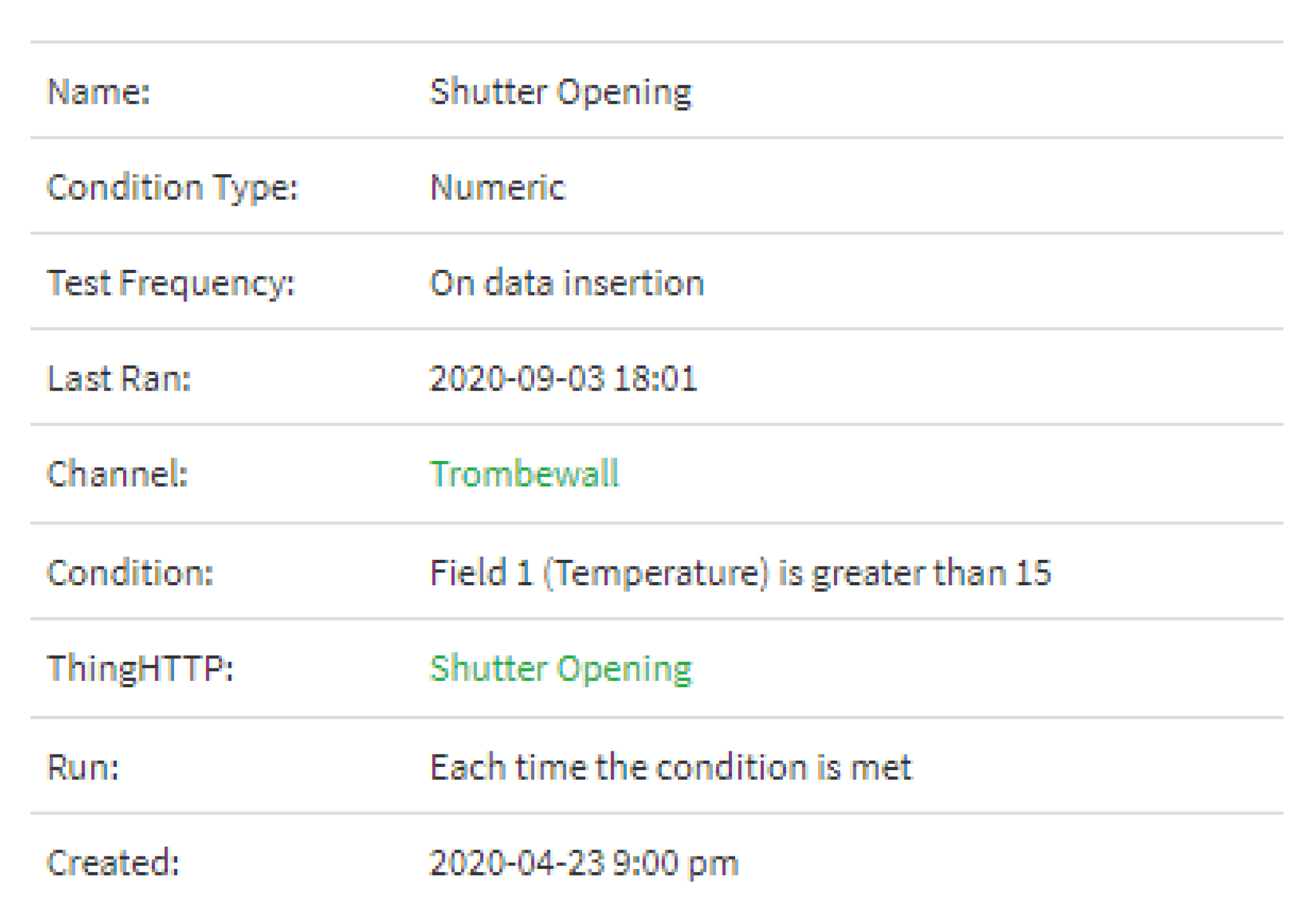
The same process is repeated to the received sensor values inside the poultry brooding (DHTi). As previously defined, actions are taken according to the temperature differential between the air gap and the interior of the poultry house (Tcam—Ti). With this, a new field is assigned (field 1) to the temperature difference, where the React is acting and so an action in ThingHTTP is triggered. In one of the cases, it is defined that if the temperature difference is below 15 ºC, XPS boards are opened, and the heat flow is also allowed by air convection through the massive wall air vents (Figure 5).
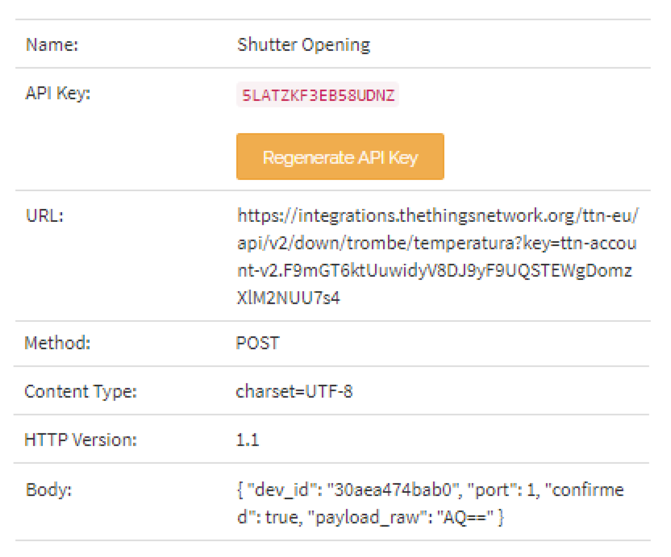
As can be seen in Figure 5, every time the temperature conditions are reached, the ThingHTTP action is unleashed, by making a POST in the downlink URL provided by The Things Network in each uplink. The body must contain the application ID and the port where the downlink is performed. If it is intended to receive an ACK from the microcontroller, the “confirmed” field should be specified and set to “true”. This information reaches the microcontroller after going through TTN, as presented in Figure 6, where the sent byte is “01”, which should be filled in base64 codification method (“AQ==”).
Right after the information is sent by the server in downlink format, the information is received when an uplink is performed from the microcontroller via LoRa as it can seen in the following portion of code. The received function previously called in LoPy4 checks which port was the information sent from, decodes the message using the hexlify() method that converts binary data to hexadecimal, and gives an instruction based on the received content. In this case, if the information received is 01, it opens the XPS boards, and if it is 00, it closes them. Once the servo “Futaba S3003” has a pulse cycle of 30 ms and a pulse width of 0.5 ms (closing) to 3 ms (opening), the required conditions are guaranteed to send a pulse of 0.5/30 = 0.017 to close the XPS boards and a pulse of 3/30 = 0.1 to open them using the PWM library.
from machine import PWM
def receive():
datainbytes = s.recvfrom(64)
message, port = datainbytes
decodedmessage = ubinascii.hexlify(message).decode()
if (port == 1):
if (decodedmessage == "00"):
print("Closing the XPS boards")
pwm_c.duty_cycle(0.017)
if (decodedmessage == "01"):
print("Opening the XPS boards")
pwm_c.duty_cycle(0.1)
Regarding the opening and closing of the external shading device, it was decided at this stage to make that decision locally. However, information is sent to the server every time the shading device operating mode changes being plotted into one field in ThingSpeak (with 0 if it is open, and 1 if it is closed).
3. Results and Discussion
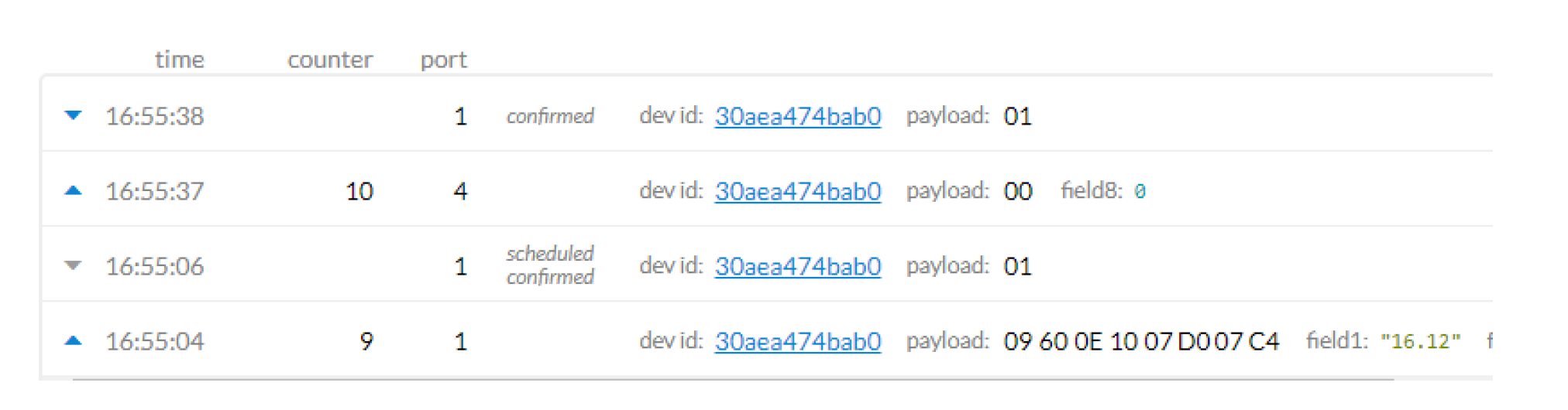
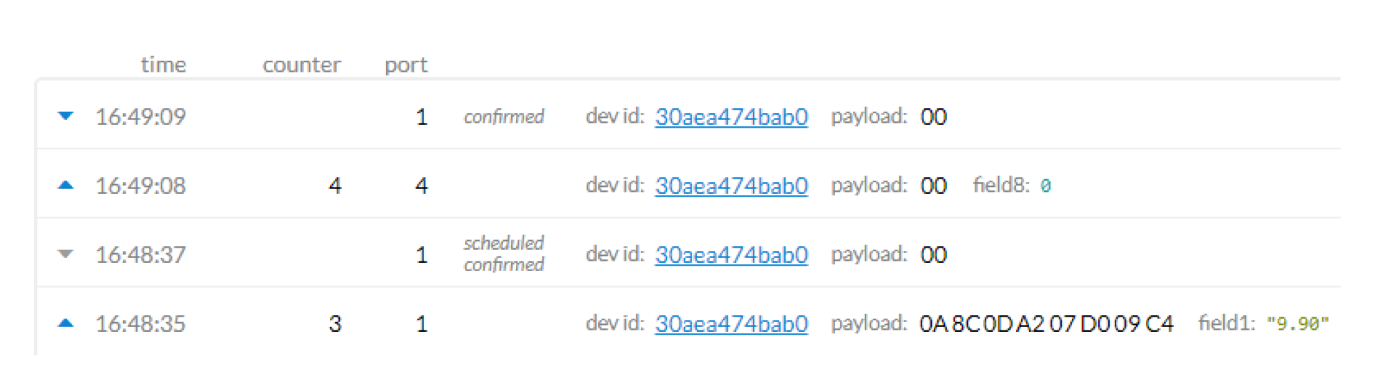
In Figure 7 and Figure 8, it is possible to observe in the “payload” field the information arrival, in bytes, obtained from the temperature sensors located in the air gap and in the internal environment to the TTN platform (server). The corresponding response is also presented, as well as the Device ID and the time of the message. As previously referenced, the data are converted to decimal values throughout a decoder for further graphical plotting in ThingSpeak application. However, field 1 plays the key role to make a decision, once it gives the temperature differential between both sensors (DHTcam—DHTi). As pointed out, if that temperature range is below 10 °C, React and ThingHTTP schedule the downlink of one byte “00” in TTN, which in the microcontroller interpretation are closing the XPS boards. If the difference is higher than 15 °C, it schedules the downlink of “01”, which gives the instruction to open the XPS boards. Additionally, as it is only possible to do a downlink schedule and the microcontroller also uplinks the external shading device state (0 if closed, 1 if opened, and controlled by the microcontroller’s Real Time Clock), the server takes advantage of that and makes the downlink (send the data to the microcontroller while the receiving window is open). In this case, in order to save energy, a class A LoRa device is implemented, meaning that it is only possible to schedule downlinks, and therefore, the microcontroller only has a brief receive window after uploading a message to the server. As the proceeding of opening/closing the XPS boards is not urgent relatively to the frequency that data are sent from the end-node to the server, it can be performed in the next uplink, as seen in Figure 7 and Figure 8.
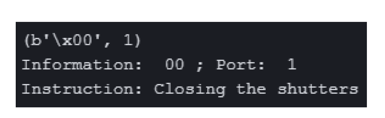
In the microcontroller, the recvfrom function returns the data in bytes, followed by the port by which the data were sent from the server. In Figure 9, after parsing the received information, the closing instruction of the XPS boards can be observed, after being analyzed.
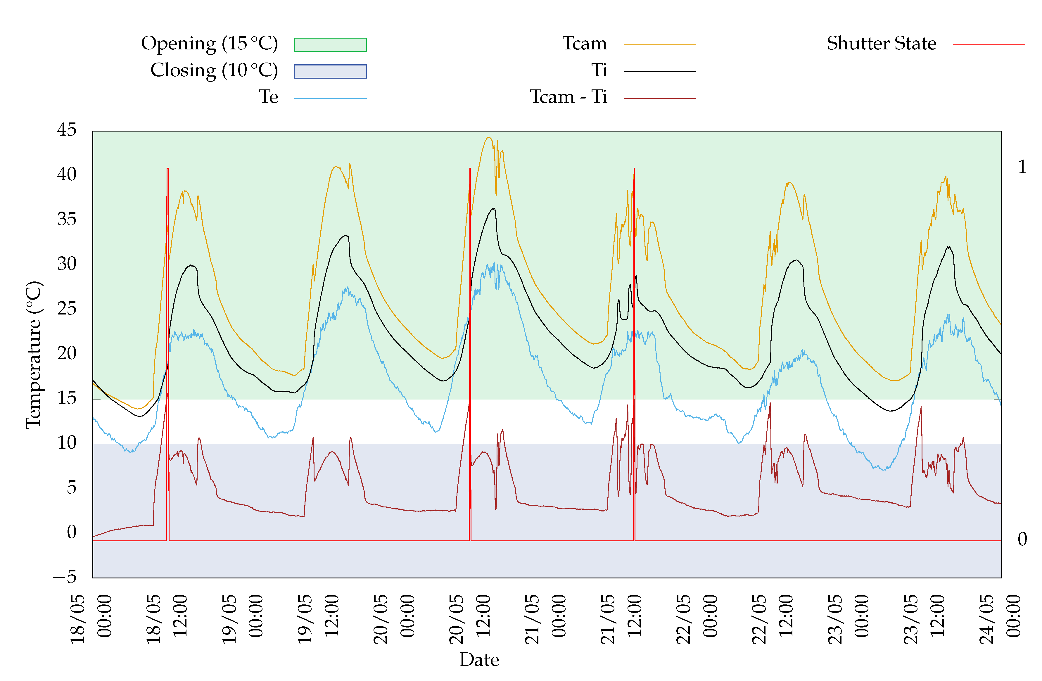
The graph presented in Figure 10 shows the temperatures values acquired during one week measurement period, when the experimental device was subjected to the climate conditions of a northern Portuguese city. Temperature measurements were made every five minutes. A data set of 1730 values was stored. As mentioned previously, the air vents opened when the temperature differential between the air gap and the interior was higher than 15 °C and closed when it was lower than 10 °C.
Although the daily opening periods of the XPS boards were reduced, the maximum temperature values compatible with brooding were easily achieved but not exceeded. In general, the higher values of interior temperatures were obtained when compared with the ones obtained outside, showing the influence of the heat storage capacity and heat delay of the Trombe wall system when integrated in the envelope of a poultry brooding building. Although this study constitutes a first approach to the implementation of a passive solar system remotely controlled by a long-range and low-cost wireless technology, it is possible to observe the suitability of these solutions to other types of buildings that are not residential or commercial, as usual, such as poultry brooding where controlled indoor temperatures are required. The obtained results show the crucial role of the air vents management to guarantee the interior comfort with low temperature fluctuations. Thus, sending a decision remotely to open or close the XPS boards contributes to the Trombe wall thermal performance optimization. Opening the XPS boards during winter periods improves the heat transfer through the air vents so higher temperatures values can be easily achieved inside the room. The XPS boards can also be very useful in the cooling season to avoid overheating as it was concluded in [8].In this research work, as referred previously, an automation and control system was also developed to open or close the air vents and the external shading device, depending on the temperature variation. However, the management of the Trombe wall operating modes was performed locally, and no long-range technology was used to support a decision. In this context, it is intended with the research work here presented to support and improve that system, implementing remote access that allows the user to consult the acquired data in ThingSpeak where decisions are taken, unnoticeably, to control the XPS boards.The results allowed one to conclude that higher temperatures are guaranteed during the day inside the brooding house. During the night periods, lower interior temperature values were obtained showing that additional heating systems can be required depending on the brooding age. However, the implementation of this solution contributes to the reduction of energy consumption to ensure the interior comfort of the space, taking into account that part of the energy needed results from the use of renewable energy sources, in this case, solar energy. Applying this system can be a contribution to maintaining the interior comfort temperature. Furthermore, it can also be shown that the proposed low-powered and low-cost system can be very useful for optimizing the poultry brooding indoor temperatures, while the building thermal comfort conditions can be easily seen using a web interface.
4. Conclusions
The research work here presented allowed us to conclude that LoRa is an effective way of communicating across long distances using low-powered devices, despite working with low data rates. However, it proved to be a suitable technology to be applied to the Trombe wall case, given that air vents control only requires low data packets to be sent to the network. Furthermore, this technology is characterized by a long range, fitting the purpose, once brooding houses are normally located in large fields that are not reachable by other wireless technologies. The wireless automation of the Trombe wall to the poultry brooding house was successfully idealized, given that it was possible to manage the air vents operating modes by opening or closing the XPS boards in order to control the temperature fluctuation inside the building. In this particular case, it was also concluded that the use of the Trombe wall system is not enough to guarantee the required brooding temperatures during all periods of growth and may require the simultaneous use of other cooling devices. However, it can also be concluded that costs can be reduced by using a renewable energy source. Furthermore, the further optimization of the Trombe wall thermal performance can be performed, namely in what concerns the geometry and material details, as well as air vents management. The advantages of using a low-powered wireless control system that can be used to remotely manage and optimize the Trombe wall thermal performance, as long as there is a gateway in the region, should also be noted.
Therefore, it can be stated that the main goal of this research work is to save energy by unifying these two technologies: the Trombe wall system and LoRaWAN network topology that uses LoRa modeling. By escalating this low-powered system, it can be applied to mass chicken production, providing a web interface that shows the indoor conditions that can be remotely controlled if needed.
This experimentation can be very useful once a future network structure can be deployed and decisions can be taken in a central server, delivered by a gateway that could be listening to several devices from different brooding houses, or even from other LoRaWAN secure applications that can be controlled unobtrusively while the end-nodes consume low power, similarly to the one designed in this work.
As future work, once the used sensors also return humidity values, it is necessary to investigate in which way it may affect the chickens in the early gestation of their living and how the Trombe wall can have a better performance based on this proposed conditions. In addition, further studies are also needed concerning the use of different modeling techniques, the influence of the transmission environment and data set structures, as well as a better understanding of a LoRaWAN mesh. Furthermore, as it is a low-energy-consumption system, it could also be implemented with a solar photovoltaic panel.
This research work highlights the advantages of the Internet of Things and its applicability in several daily situations. Moreover, it is a project that involves distinct areas inside engineering and brings them into a common work.
Author Contributions
Conceptualization, A.V., A.B.-S. and A.M.; methodology, A.V. and A.B.-S.; software, A.M.; validation, A.V., A.B.-S. and A.M.; writing—original draft preparation, A.M.; writing—review and editing, A.M., A.B.-S. and A.V.; visualization, A.M.; supervision, A.V. and A.B.-S.; project administration, A.V. and A.B.-S.; funding acquisition, A.V. and A.B.-S. All authors have read and agreed to the published version of the manuscript.
Funding
The research leading to these results has received funding by National Funds through the Portuguese funding agency, FCT—Fundação para a Ciência e a Tecnologia within project PTDC/CCI-INF/29583/2017 (POCI-01-0145-FEDER-029583).
Institutional Review Board Statement
Not applicable.
Informed Consent Statement
Not applicable.
Conflicts of Interest
The authors declare no conflict of interest.
References
- Nwakonobi, T.; Obetta, S.; Gabi, M. Evaluation of a Modified Passive Solar Housing System for Poultry Brooding. J. Sci. Technol. (Ghana) 2013, 33, 50. [Google Scholar] [CrossRef] [Green Version]
- Okonkwo, W.I.; Akubuo, C.O. Design, Construction and Performance Evaluation of a Trombe Wall Poultry Chick Brooding House. In Proceedings of the ASABE Annual International Meeting, Detroit, MI, USA, 29 July–1 August 2018; American Society of Agricultural and Biological Engineers: St. Joseph, MI, USA, 2018. [Google Scholar] [CrossRef]
- Okonkwo, W.I.; Akubuo, C.O. Trombe wall system for poultry brooding. Int. J. Poult. Sci. 2007, 6, 125–130. [Google Scholar] [CrossRef]
- Ahmed, O.K. Recent Advances in Photovoltaic-Trombe Wall System: A Review. In Renewable Energy [Working Title]; IntechOpen: London, UK, 2020. [Google Scholar] [CrossRef] [Green Version]
- Briga-Sá, A.; Boaventura-Cunha, J.; Lanzinha, J.C.; Paiva, A. Experimental and analytical approach on the Trombe wall thermal performance parameters characterization. Energy Build. 2017, 150, 262–280. [Google Scholar] [CrossRef]
- Sá, A.B.; Boaventura-Cunha, J.; Lanzinha, J.C.; Paiva, A. An experimental analysis of the Trombe wall temperature fluctuations for high range climate conditions: Influence of ventilation openings and shading devices. Energy Build. 2017, 138, 546–558. [Google Scholar] [CrossRef] [Green Version]
- Briga-Sá, A.; Paiva, A.; Lanzinha, J.C.; Boaventura-Cunha, J.; Fernandes, L. Influence of Air Vents Management on Trombe Wall Temperature Fluctuations: An Experimental Analysis under Real Climate Conditions. Energies 2021, 14, 5043. [Google Scholar] [CrossRef]
- de Sousa Fernandes, L.P. Definição de um Sistema de Controlo e Automação para Otimização do Desempenho Térmico da Parede de Trombe. Master’s Thesis, Universidade de Trás-os-Montes e Alto Douro, Vila Real, Portugal, 2017. [Google Scholar]
- Mikhailov, M.S.; Strelkov, N.O. Application of Wi-Fi and LoRa Technologies for Wireless Measurement of Physical Quantities. In Proceedings of the 2019 International Youth Conference on Radio Electronics, Electrical and Power Engineering (REEPE), Moscow, Russia, 14–15 March 2019; pp. 1–4. [Google Scholar]
- Valerio, P. Top Wireless Standards for IoT Devices, Blog. 2019. Available online: https://iot.eetimes.com/top-wireless-standards-for-iot-devices/ (accessed on 30 September 2021).
- Khakimov, A.; Muthanna, A.; Kirichek, R.; Koucheryavy, A.; Muthanna, M. Investigation of methods for remote control IoT-devices based on cloud platforms and different interaction protocols. In Proceedings of the 2017 IEEE Conference of Russian Young Researchers in Electrical and Electronic Engineering (EIConRus), St. Petersburg/Moscow, Russia, 1–3 February 2017. [Google Scholar] [CrossRef]
- A technical overview of LoRa® and LoRaWAN™. Technical Paper from Semtech. Available online: https://lora-alliance.org/wp-content/uploads/2020/11/what-is-lorawan.pdf (accessed on 2 July 2020).
- Staniec, K.; Kowal, M. LoRa Performance under Variable Interference and Heavy-Multipath Conditions. Wirel. Commun. Mob. Comput. 2018, 2018, 1–9. [Google Scholar] [CrossRef]
- Team, The Things Network Global. LoRaWAN® Distance World Record Broken, Twice. 766 km (476 miles) Using 25 mW Transmission Power. Blog. Available online: https://www.thethingsnetwork.org/article/lorawan-distance-world-record (accessed on 5 July 2020).
- Ray, B.; What Is LoRa? A Technical Breakdown. Blog. Available online: https://www.link-labs.com/blog/what-is-lora (accessed on 5 July 2020).
- Augustin, A.; Yi, J.; Clausen, T.H.; Townsley, W. A Study of LoRa: Long Range & Low Power Networks for the Internet of Things. Sensors 2016, 16, 1466. [Google Scholar] [CrossRef]
- Lauridsen, M.; Vejlgaard, B.; Kovacs, I.Z.; Nguyen, H.; Mogensen, P. Interference Measurements in the European 868 MHz ISM Band with Focus on LoRa and SigFox. In Proceedings of the 2017 IEEE Wireless Communications and Networking Conference (WCNC), San Francisco, CA, USA, 19–22 March 2017. [Google Scholar]
- Springer, A.; Gugler, W.; Huemer, M.; Reindl, L.; Ruppel, C.; Weigel, R. Spread spectrum communications using chirp signals. In Proceedings of the IEEE/AFCEA EUROCOMM 2000. Information Systems for Enhanced Public Safety and Security (Cat. No.00EX405), Munich, Germany, 19 May 2000; pp. 166–170. [Google Scholar] [CrossRef]
- What are LoRa® and LoRaWAN®? Tech Paper. Available online: https://lora-developers.semtech.com/library/tech-papers-and-guides/lora-and-lorawan/ (accessed on 29 September 2021).
- LoRaWAN Architecture, Documentation. 2020. Available online: https://www.thethingsnetwork.org/docs/lorawan/architecture.html (accessed on 29 September 2021).
- LoRaWAN Spreading Factor, Range, DATA rate in LoRa System. Available online: https://www.rfwireless-world.com/Terminology/LoRaWAN-Spreading-factor-Range-and-Data-Rate.html (accessed on 29 September 2021).
- Limitations: Data Rate, Packet Size, 30 s Uplink and 10 Messages Downlink per day Fair Access Policy [Guidelines], Forum. 2020. Available online: https://www.thethingsnetwork.org/forum/t/fair-use-policy-explained/1300 (accessed on 29 September 2021).
- Lie, R. LoRa/LoRaWAN Tutorial 19: LoRa End Nodes. Available online: https://www.youtube.com/watch?v=vMMFCxzSP_s&t=6s (accessed on 29 September 2021).
- SX1272/3/6/7/8: LoRa Modem Designer’s Guide. Designer’s Guide. Available online: https://www.rs-online.com/designspark/rel-assets/ds-assets/uploads/knowledge-items/application-notes-for-the-internet-of-things/LoRa%20Design%20Guide.pdf (accessed on 28 September 2021).
- LoRa® Gateways, Semtech’s Products Page. 2020. Available online: https://www.semtech.com/products/wireless-rf (accessed on 29 September 2021).
- Network Security, Forum. 2020. Available online: https://www.thethingsnetwork.org/docs/network/security/ (accessed on 29 September 2021).
- React App. Documentation. Available online: https://www.mathworks.com/help/thingspeak/react-app.html (accessed on 29 September 2021).
- ThingHTTP App. Documentation. Available online: https://www.mathworks.com/help/thingspeak/thinghttp-app.html (accessed on 29 September 2021).
- Liu, Y.; Wang, D.; Ma, C.; Liu, J. A numerical and experimental analysis of the air vent management and heat storage characteristics of a trombe wall. Sol. Energy 2013, 91, 1–10. [Google Scholar] [CrossRef]
- Pfeffer, Z. DevEUI, AppEUI (JoinEUI) and AppKey. 2018. Available online: https://www.centennialsoftwaresolutions.com/post/deveui-appeui-joineui-and-appkey (accessed on 29 September 2021).
- Security. 2020. Available online: https://www.thethingsnetwork.org/docs/lorawan/security.html (accessed on 29 September 2021).
- LoRaWAN™ SECURITY, White Paper. 2017. Available online: https://lora-alliance.org/sites/default/files/2019-05/lorawan_security_whitepaper.pdf (accessed on 2 August 2020).
- ThingHTTP, Forum. 2014. Available online: https://community.thingspeak.com/documentation.../apps/thinghttp/ (accessed on 29 September 2021).
- Raftery, H. LoRaWAN: OTAA or ABP? 2018. Available online: https://www.newieventures.com.au/blogtext/2018/2/26/lorawan-otaa-or-abp (accessed on 4 August 2020).
- Pycom Go Invent. LoPy4 Version 1.1, Datasheet. Available online: https://docs.pycom.io/gitbook/assets/specsheets/Pycom_002_Specsheets_LoPy4_v2.pdf (accessed on 29 September 2021).
- The Things Network. The Things Gateway Datasheet. Available online: http://www.farnell.com/datasheets/2552236.pdf?_ga=2.173850791.580724957.1597865279-1450960015.1597865279 (accessed on 29 September 2021).
- Lange, E.D.; Project Title. GitHub Page. 2019. Available online: https://github.com/erikdelange/WiPy-2.0-DHT22 (accessed on 29 September 2021).
Figure 1.
CSS illustration (Up-Chirp).

Figure 2.
LoRaWAN star topology. Reprinted from Ref. [12]
Figure 2.
LoRaWAN star topology. Reprinted from Ref. [12]

Figure 3.
Illustration of the control system.

Figure 4.
Block diagram of the implemented network.

Figure 5.
Implemented React to open the XPS boards.

Figure 6.
Implemented ThingHTTP to open the XPS boards.

Figure 7.
Opening the XPS boards (field1 > 15 °C).

Figure 8.
Closing the XPS boards (field1 < 10 °C).

Figure 9.
Reception in the microcontroller.

Figure 10.
Temperature values (Exterior—Te; Interior—Ti; Air gap—Tcam).


Table 1.
LoRa extension.
| Environment | Reach (km) |
|---|---|
| Urban Areas | 2–5 |
| Rural Areas | 5–15 |
| Line of Sight | >15 |
Table 2.
Values of an 11 byte packet for different SF.
| Spreading Factor | Bit Rate | Range | Time on Air |
|---|---|---|---|
| SF10 | 980 bps | 8 km | 371 ms |
| SF9 | 1760 bps | 6 km | 185 ms |
| SF8 | 3125 bps | 4 km | 103 ms |
| SF7 | 5470 bps | 2 km | 61 ms |
Table 3.
Data Rate, Spreading Factor and Bandwidth dependence. Reprinted from Ref. [21]
Table 3.
Data Rate, Spreading Factor and Bandwidth dependence. Reprinted from Ref. [21]
| Data Rate | Configuration | bits/s |
|---|---|---|
| DR0 | SF12/125 KHz | 250 |
| DR1 | SF11/125 KHz | 440 |
| DR2 | SF10/125 KHz | 980 |
| DR3 | SF9/125 KHz | 1760 |
| DR4 | SF8/125 KHz | 3125 |
| DR5 | SF7/125 KHz | 5470 |
Table 4.
Boards state regarding the temperature differential.
| DHTcam—DHTi | XPS Boards State |
|---|---|
| >15 °C | Open (01) |
| <10 °C | Closed (00) |
Publisher’s Note: MDPI stays neutral with regard to jurisdictional claims in published maps and institutional affiliations. |
© 2021 by the authors. Licensee MDPI, Basel, Switzerland. This article is an open access article distributed under the terms and conditions of the Creative Commons Attribution (CC BY) license (https://creativecommons.org/licenses/by/4.0/).
Share and Cite
MDPI and ACS Style
Mota, A.; Briga-Sá, A.; Valente, A. Development of a Wireless System to Control a Trombe Wall for Poultry Brooding. AgriEngineering 2021, 3, 853-867. https://0-doi-org.brum.beds.ac.uk/10.3390/agriengineering3040054
AMA Style
Mota A, Briga-Sá A, Valente A. Development of a Wireless System to Control a Trombe Wall for Poultry Brooding. AgriEngineering. 2021; 3(4):853-867. https://0-doi-org.brum.beds.ac.uk/10.3390/agriengineering3040054
Chicago/Turabian StyleMota, Afonso, Ana Briga-Sá, and António Valente. 2021. "Development of a Wireless System to Control a Trombe Wall for Poultry Brooding" AgriEngineering 3, no. 4: 853-867. https://0-doi-org.brum.beds.ac.uk/10.3390/agriengineering3040054