Technical Note

An Integrated Plastic Contamination Monitoring System for Cotton Module Feeders

1
United States Department of Agriculture, Agricultural Research Service, Cotton Production and Processing Research Unit, Lubbock, TX 79403, USA
2
Cotton Incorporated, Cary, NC 27513, USA
3
John Deere, Des Moines Works, Des Moines, IA 50306, USA
4
TAMA Group, Kibbutz Mishmar HaEmek, Tel Aviv 1923600, Israel
*
Author to whom correspondence should be addressed.
Submission received: 6 October 2021 / Revised: 9 November 2021 / Accepted: 19 November 2021 / Published: 23 November 2021

Abstract

:
Plastic contamination in US lint bales has increased with the adoption of new cotton harvesters that form cylindrical or round modules on the machine. It is of significant interest to the US cotton industry to reduce this contamination to preserve grower profitability and the reputation of the US as a reliable source of clean cotton fiber. The objective of this work is to describe the design and operation of a system for use on cotton gin module feeders that provides monitoring of plastic accumulation on the dispersing cylinders and video data to help document the module wrap condition and unloading/unwrapping procedures that may have caused the potential contamination event on the dispersing cylinders. In 2020, an integrated plastic contamination monitoring system was installed on module feeders at two commercial cotton gins in Texas. The system is comprised of sub-systems that provide images of plastic accumulation on the dispersing cylinders, a log of the processing sequence for round modules, video data of the unloading/unwrapping process for each module and a software program that integrates the data from the two sub-systems. The system was developed to operate on one computer, store the data in a common location, and simplify the process of extracting module specific data for a given event when plastic accumulates on the module feeder dispersing cylinders. The data provided by the system can be useful to manufacturers in comparing performance among module wrap products as well as to gin managers in training gin employees on module handling procedures to mitigate plastic contamination and improve worker safety.

1. Introduction

New cotton harvesters that form cylindrical modules onboard the machine (7760, CP/CS690, and CP/CS770, John Deere, Moline, IL, USA) have reduced labor and machinery requirements and increased cotton harvesting productivity. Cylindrical modules (commonly referred to as “round” modules) are about 2.4 m long, 2.4 m in diameter, and weigh between 2000 and 2500 kg each. Round modules are wrapped in plastic by the harvester before they are ejected in the field. The plastic module wrap material restrains the seed cotton in cylindrical form and protects it from quantity and quality losses caused by environmental effects experienced during storage before ginning. Four passive radio frequency identification (RFID) tags are embedded in each individual module wrap portion and return a module specific identification number when remotely interrogated.
Plastic contamination in US lint bales (218 kg/bale) has increased with the rapid adoption of round module building cotton pickers and strippers [1]. As a result, in 2018, USDA Agricultural Marketing Service adopted new extraneous matter classing codes 71 and 72 for plastic contamination levels 1 and 2, respectively. Since August 2019, spot quotations for lint bales with any plastic contamination designation contain a $0.88/kg ($0.40/lb) discount [2] and merchants and mills often refuse to purchase bales with plastic contamination. Most recently, the 2021 USDA CCC loan schedule of premiums and discounts for upland cotton [3] contains discounts of $0.6900 and $0.7143 per kg of lint for bales classed with 71 and 72 extraneous matter designations, respectively. Contamination has contributed significantly to the loss of the price premium US cotton once received on the international fiber market in comparison to cotton of similar quality from other growing areas. US cotton now trades at a discount relative to cotton from these other areas for a total estimated loss of USD 0.15/kg which costs the US cotton industry between USD $350 and $750 million annually depending upon the size of the crop [4,5]. Thus, prevention and/or detection and removal of plastic contamination is of keen interest to US cotton growers in efforts to maximize profitability and maintain the reputation of the United States as being a reliable source of clean cotton fiber.
The movement and handling of modules in the field, during transportation, and at the cotton gin can damage the wrap material, leading to potential wrap failures and plastic contamination in lint bales [5,6]. Additionally, the technique used to cut and remove wrap from round modules can lead to increased risk of plastic contamination if pieces of plastic remain with the cotton as it is fed into the gin by the module feeder [7]. Cotton gin module feeders use a series of spiked rollers, known as dispersing cylinders, to break apart cotton modules and feed the separated material into the ginning process (Figure 1). The annual ginning capacity (lint bales ginned per year) of a cotton gin varies with the local crop size, but a gin that processes 50 bales (218 kg/bale) of cotton lint per hour consumes about 12–18 round modules of seed cotton depending upon harvest method. Cotton modules are placed on the feeder bed by a transport vehicle at the opposite end of the feeder from the dispersing cylinders (the intake end, Figure 2). Plastic wrap is removed from round modules at the intake end of the module feeder before they are transported by the feeder bed to the dispersing cylinders. Often, plastic remaining in the cotton as it is engaged by the dispersing cylinders is caught by and wrapped around the cylinders. If the plastic material is not removed from the dispersing cylinders, it will be continually shredded into small pieces by the action of the incoming modules against the cylinders and be fed into the ginning process where it can potentially contaminate many lint bales [8,9].
The objective of this work is to describe the design and operation of a novel system for use on cotton gin module feeders that documents when plastic accumulates on the module feeder dispersing cylinders (i.e., a potential plastic contamination event) and provides video data for investigation into what events or situations may have caused the potential contamination event. The system was installed and operated on two commercial cotton gin module feeders in Texas during 2020 and the information collected was useful in evaluating the condition of different module cover materials before ginning and in training gin employees on proper round module handling techniques to minimize contamination and improve worker safety.

2. System Design and Operation

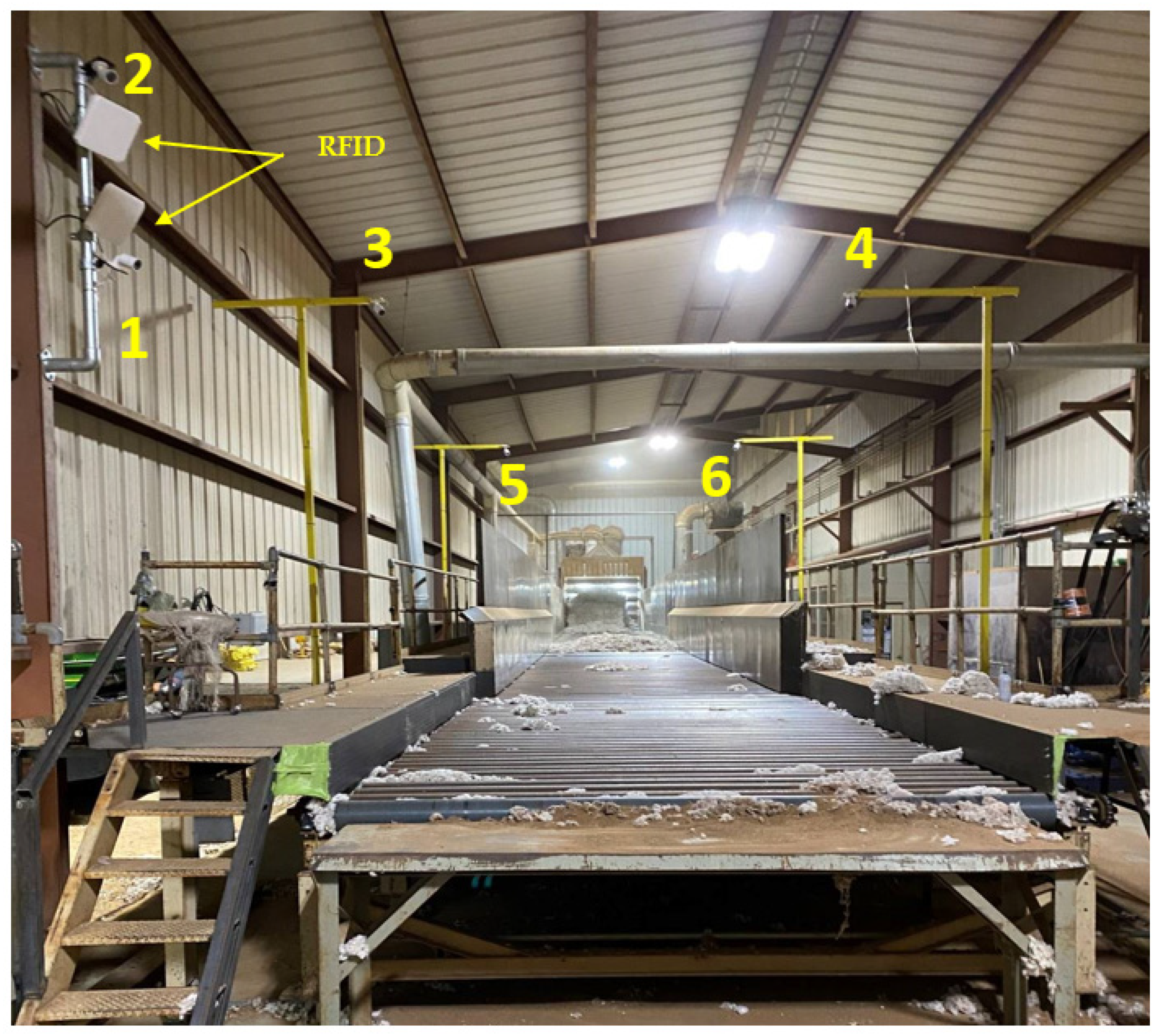
2.1. System Overview

The integrated plastic contamination monitoring system consists of two subsystems installed to monitor activities on the intake [10,11] and dispersing [12,13] ends of cotton gin module feeders and a custom written software program named Inspection Report Builder (IRB) [14] that provides integration of the data from the two subsystems. Source code files for the IRB software are provided in the Supplementary Information in this paper. The integrated plastic contamination monitoring system is the first system developed that detects when a potential contamination event occurs on a cotton gin module feeder and provides data useful to gin workers and managers in the investigation into the root causes that produced the potential contamination event.
The RFID Feeder Bridge system [10,11] was installed on the intake end of the module feeders to interrogate RFID tags included in the plastic film covering each module and create a processing log showing the date and time that each module was placed on the module feeder. Network cameras were installed on the module feeders at key locations to record the condition of module covers just prior to removal and the sequence of events used to remove the cover and place a module on the feeder bed. Video recorded by the system was triggered by the RFID scan event for each module.
On the opposite end of the module feeder, the USDA Module Feeder Inspector System (MFIS) [12,13] was installed to monitor the dispersing cylinders for accumulation of module cover plastic and other contaminants. The USDA MFIS collected still images of the dispersing cylinders when the in-feed of cotton was temporarily paused on a preprogrammed frequency. Pausing the feeder bed allowed cotton and debris to fall out of the camera view, thus producing a clear image of the cylinders and any accumulation of contaminants. Time stamped still images captured by the MFIS were stored on the local computer operating the RFID Feeder Bridge and USDA MFIS software.
The IRB software [14] integrated data collected by the RFID Feeder Bridge and USDA MFIS systems to facilitate the root cause analysis for each event in which plastic accumulation was observed on the dispersing cylinders. When plastic accumulation was observed in the still images of the dispersing cylinders, the corresponding video of the module(s) from which the plastic originated was easily extracted using the report generated by the IRB software.

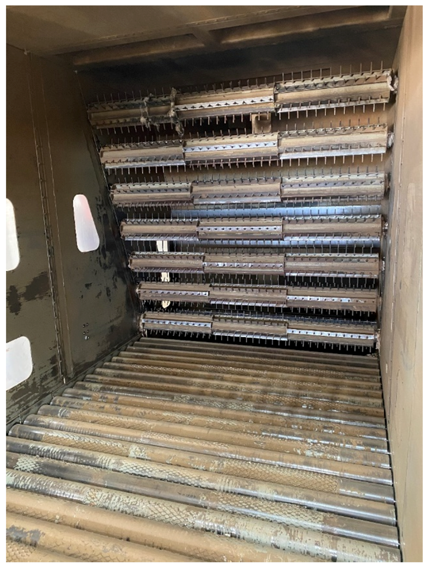
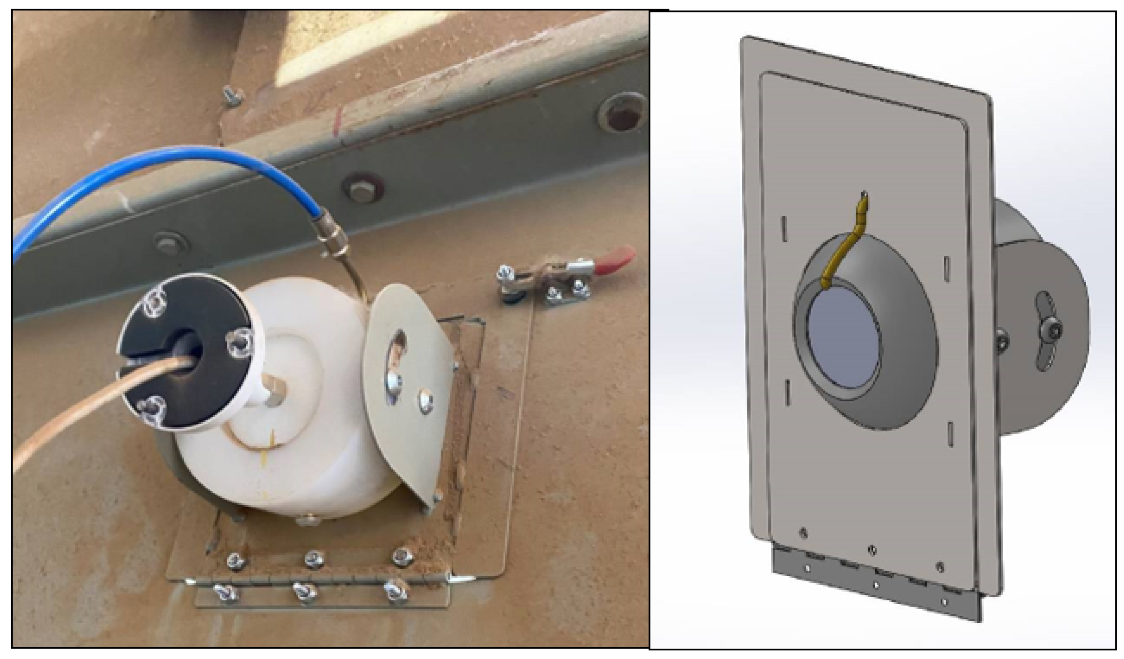
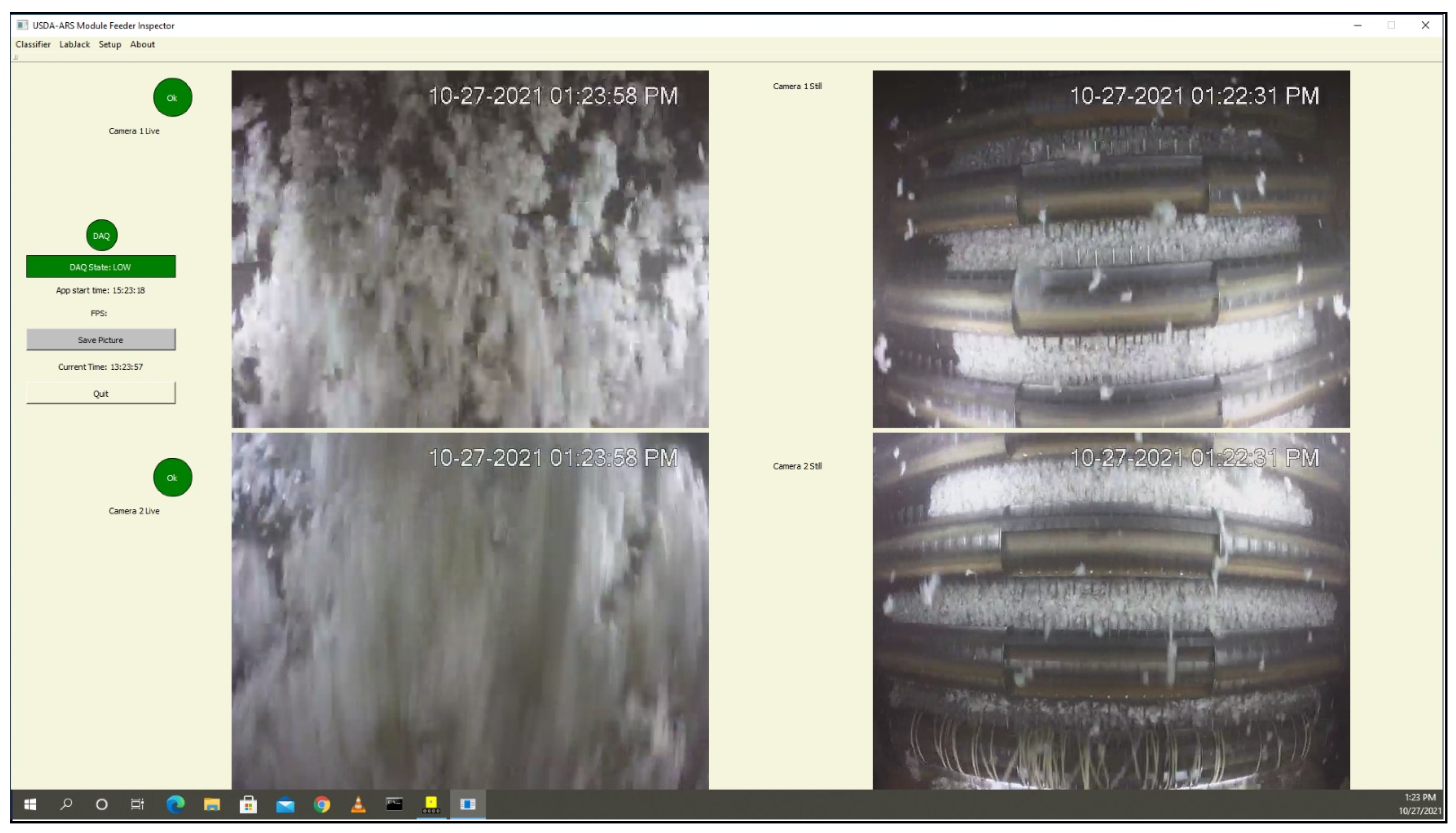
2.2. Subsystem 1: Module Feeder—Intake End

The RFID Feeder Bridge system [10,11] was deployed at the intake end of the module feeders to scan the RFID tags contained in the plastic wrap on each round module and create a timestamped processing log for all modules placed onto the module feeder (Figure 3). The plastic material covering each round module contained four passive ultra-high frequency RFID tags that were affixed to the plastic film by the manufacturer during production. The RFID tags in each individual module cover portion were preprogrammed by the manufacturer with a hexadecimal module identifier string that contained a serial number unique to each module. Two left-hand circular polarized antennas (PAL90209H, Laird Connectivity, Akron, OH, USA) were mounted approximately 4 m above the location where modules were placed onto the feeder bed to interrogate the RFID tags in each module. Radio frequency energy from the antennae was focused on a circular region (approximately 3–4 m diameter) centered about 2.5 m above the first roller on the module feeder bed. The antennas were controlled by an RFID reader (Speedway R420, Impinj, Seattle, WA, USA) that transferred RFID scan data (module identifier and scan timestamp) to custom written software running on a Windows 10 (Microsoft, Redmond, WA, USA) ruggedized computer (K300, OnLogic, South Burlington, VT, USA) through a power over ethernet (PoE) connection. The RFID Feeder Bridge software generated a datafile containing a time-ordered list of the following data for each module scanned: date and time of scan event, module serial number, cotton ownership data (client/farm/field), cotton cultivar, wrap color, and gin load number.
Each time an RFID scan event occurred on the module feeder, the RFID Feeder Bridge software triggered a pre-buffered video capture routine from six internet protocol (IP) cameras (2.8 mm fixed focal length, N41BD22, Dahua Technology, Hangzhou, China) connected to the system through a PoE switch (SG250-10P, Cisco Systems Inc., San Jose, CA, USA). Two IP cameras were positioned to record video of: (1) the condition of the wrap on each module as it was placed on the module feeder bed (camera positions 1 and 2, Figure 3), (2) the procedure used to unload the module from the transport vehicle (camera positions 3 and 4, Figure 3), and (3) the procedure used to cut and remove the plastic wrap from each module (camera positions 5 and 6, Figure 3). The six cameras fed video data to the RFID Feeder Bridge system (6 fps, 2304 × 1296 resolution, 1352 kbps bitrate) where it was temporarily buffered into memory for post processing. During post processing of the video data for each RFID scan event, the Feeder Bridge software extracted a portion of the buffered video data from before the RFID scan event and stitched it to a portion of buffered video collected after the scan event. The time segments for the pre- and post-RFID scan periods were set to 3 min and are defined by the user in the software setup. Thus, six-minute-long video files were created for each camera and the files were stored on a 2 TB removable solid-state drive (T5, Samsung, Seoul, Korea) using a file naming structure that includes the module serial number, camera number, and timestamp for the RFID scan event.

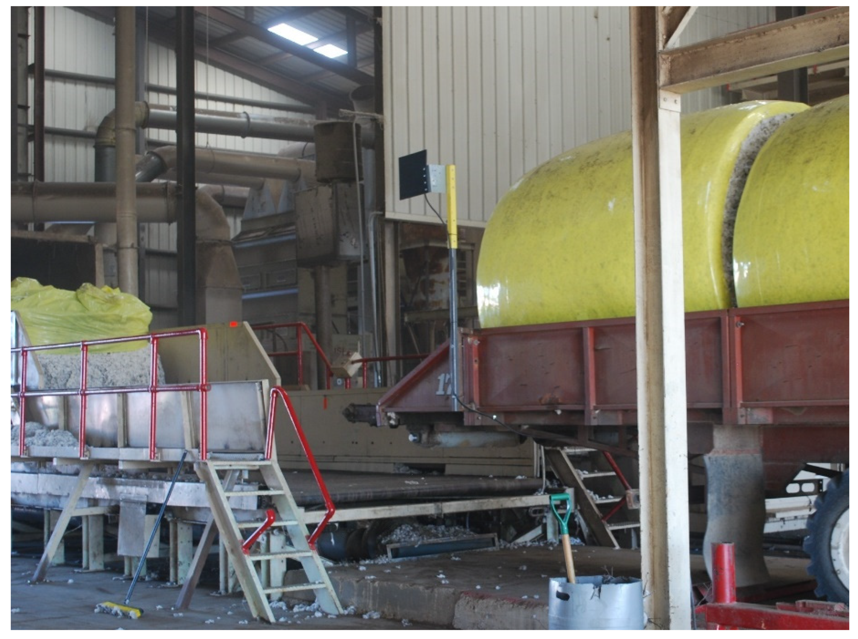
2.3. Subsystem 2: Module Feeder—Dispersing End

The USDA MFIS [12,13] was installed to monitor the accumulation of contaminants on the dispersing cylinders of the module feeders. Two IP cameras (N41BD22, Dahua Technology, Hangzhou, China) were mounted on the back wall of each module feeder and provided video of the upper and lower dispersing cylinders (Figure 4). Additional lighting was installed adjacent to the cameras to illuminate the dispersing cylinders and provided 2500 lux illuminance. Ball-faced mounts were designed and installed for use with the USDA MFIS cameras at both gins. The camera mounts allow for ± 30 degrees of camera elevation adjustment allowing the cameras to be positioned as needed on the dispersing cabinet back wall regardless of dispersing cabinet design (Figure 5). Live video from each camera was fed via PoE network connection to the USDA Module Feeder Inspection System software running on the same Windows 10 computer used to run the RFID Feeder Bridge Software. The USDA MFIS software displayed live video streams from each camera along with a set of still images showing clear views of the dispersing cylinders (Figure 6). When the module feeder dispersing cylinders are actively engaging cotton, the material being thrown toward the back wall of the feeder blocks the view of the cameras. Thus, a pause routine was programmed into the programmable logic controller (PLC) that controls the module feeder, to pause the feeder bed for 10 s every 20 min stopping the infeed of modules to the dispersing cylinders. The pause duration was set to allow the cotton and debris to fall out of camera view leaving a clear view of the dispersing cylinders and any accumulation of plastic or other contaminants on the cylinders. The PLC program actuated a dry-contact relay (RPM12F7, Schneider Electric, Rueil-Malmaison, France) during the pause period which signaled the USDA MFIS software to capture still images of the dispersing cylinders at the end of the pause period through an ethernet connected data acquisition board (T4, LabJack, Lakewood, CO, USA). The module feeder resumed normal feeding operation once the pause period elapsed. Each time plastic was observed on the dispersing cylinders, the gin crew quickly stopped the module feeder, removed the plastic, and placed it in a container labeled with the date and time of removal. A research team member visited the gin several times each week and conducted further analysis of the plastic to identify from what part of the wrap portion the material originated, how much material was collected, and the identification number of the module from the RFID tag(s) if present. Plastic pieces that accumulated on the dispersing cylinders were easily detected by gin workers using visual observation as the pieces were large (1 m by 1 m or larger) and often covered more than 0.5 m of cylinder length when wrapped around the cylinder. However, pieces of plastic wrapped around the cylinders covering only about 2–4 cm of cylinder length were also detectable.
For each feeder bed pause event, the USDA MFIS software appended data to a file that contained the feeder bed pause event number, date and timestamp of the pause event, and the file pathnames for the still images captured by the IP cameras. The still images were stored on the removable solid-state drive used to store the video data from RFID Feeder Bridge using a naming structure that included the camera name and feeder bed pause event number.

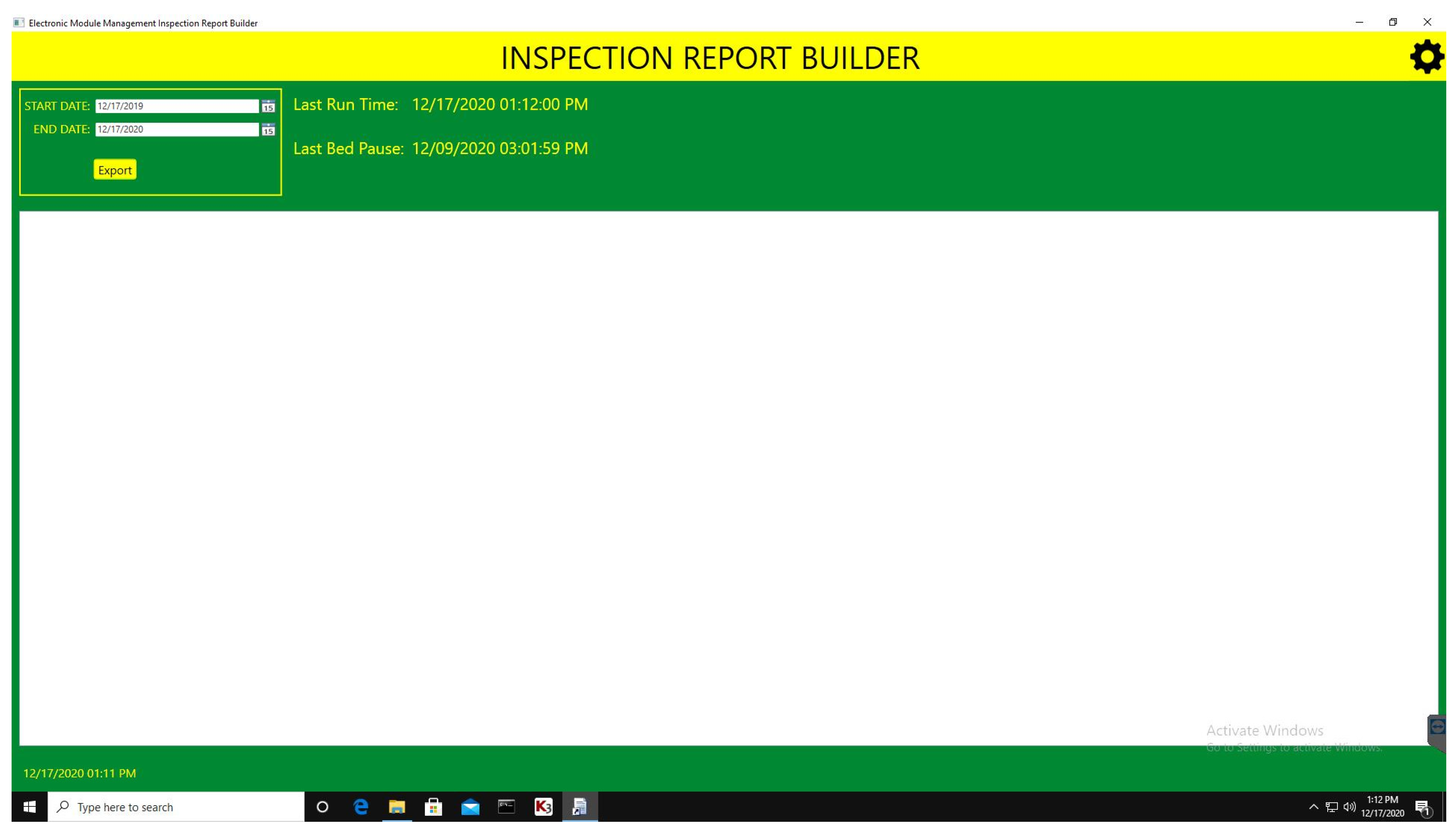
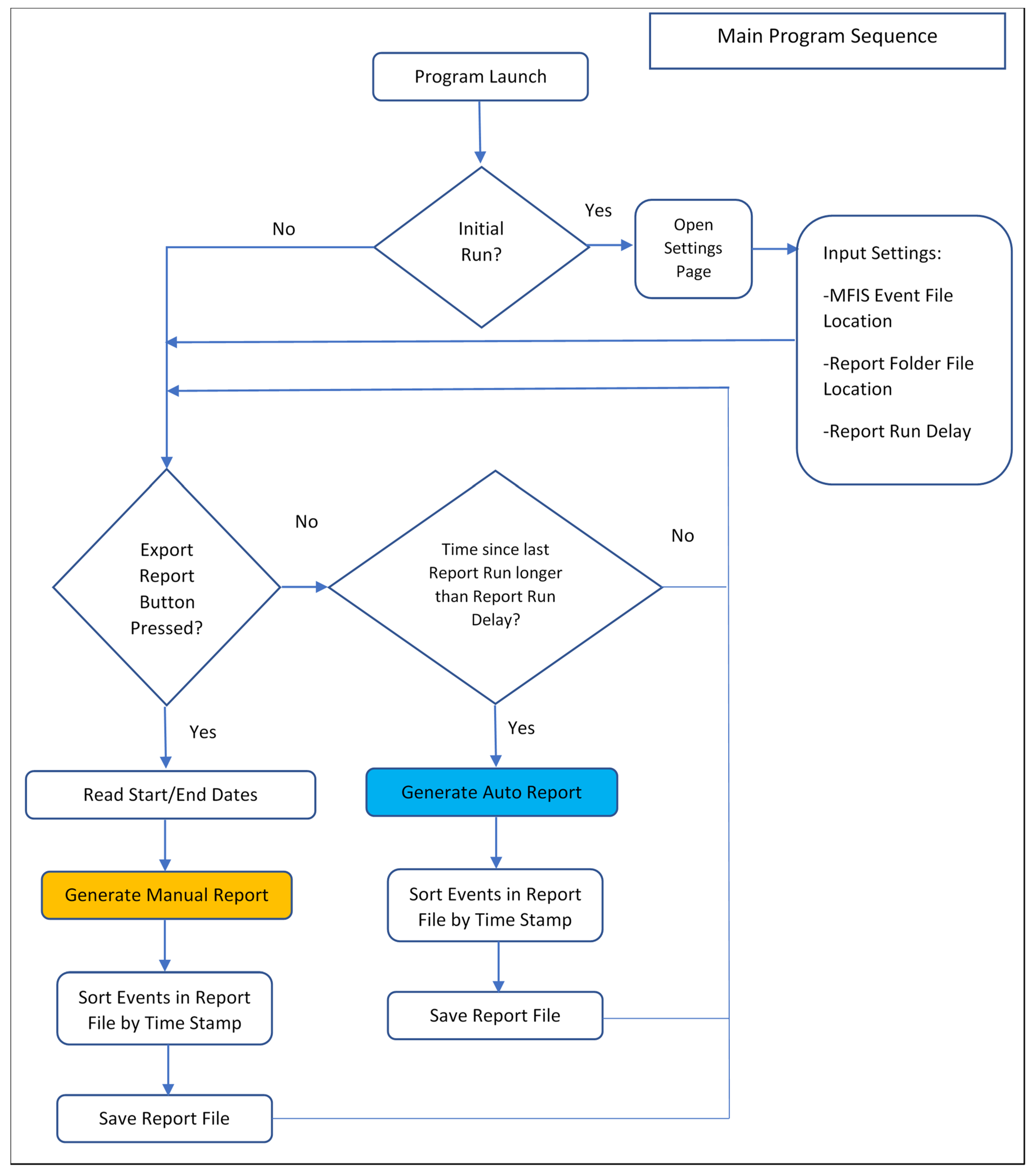
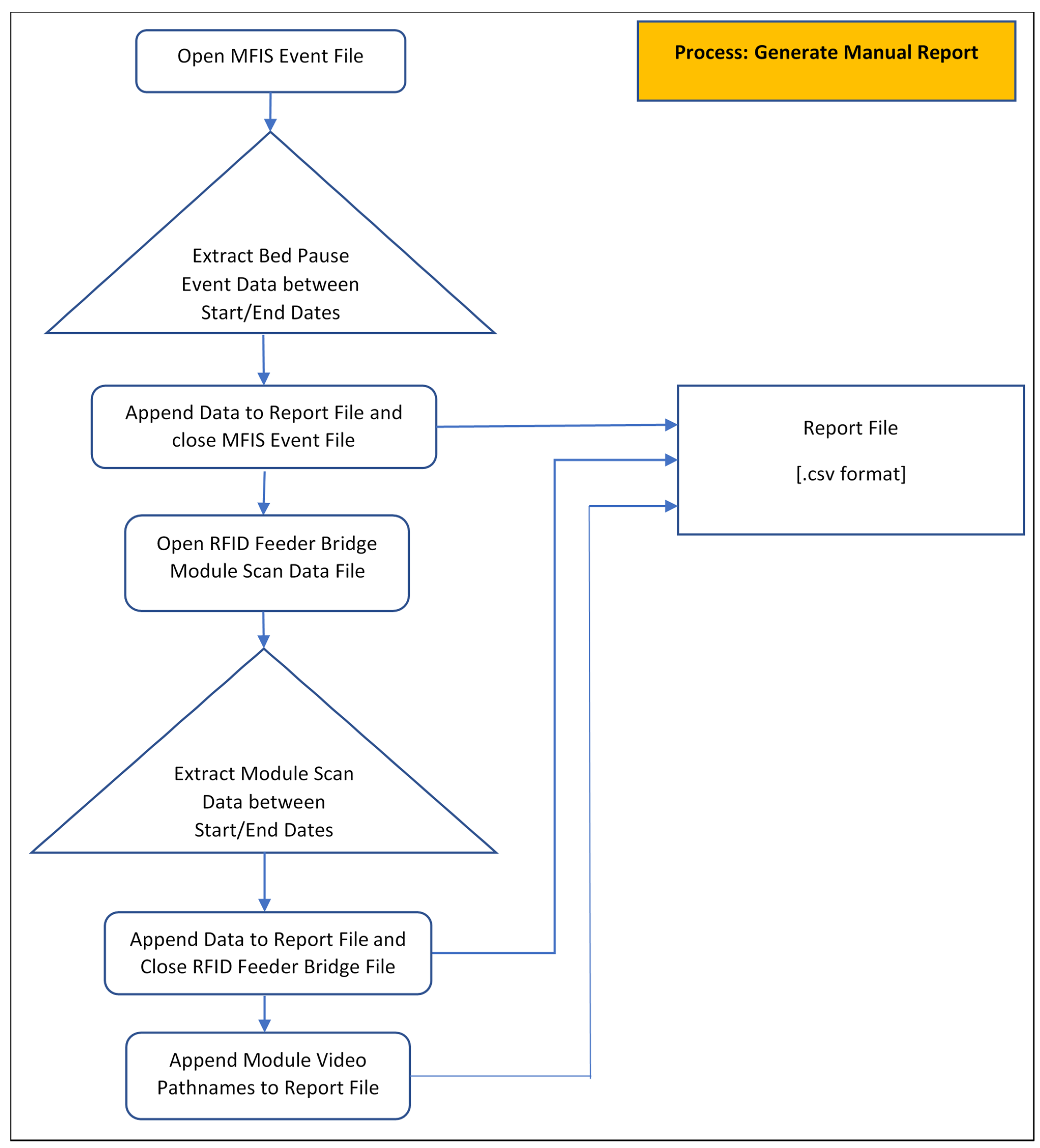
2.4. Integration Software—Inspection Report Builder

The IRB software program [14] was written to combine the data collected by the two subsystems, USDA MFIS and the RFID Feeder Bridge system. IRB was developed to run either on a continuous basis, automatically appending new data to a report file on a user specified processing interval or on a one-time, manual basis for a given time segment defined by user specified start and end dates (Figure 7). The IRB software created a comma-separated value (CSV) file that contained a time sequenced list of module feeder bed pause events separated by the module scan events that occurred between each bed pause event (Figure 8). The IRB software opened the CSV file generated by the USDA MFIS software and extracted the bed pause event number, date/timestamp, and file path names for the dispersing cylinder still images captured for each bed pause event. The IRB software then extracted the date/timestamp, module serial number, and unloading/unwrapping video file path names for each module scan event from the RFID Feeder Bridge software data file. A flow chart of the operation of the IRB software is shown in Figure 9, Figure 10 and Figure 11. The report generated by the software contained active hyperlinks to the still images and video files for each module, simplifying the extraction and inspection of those files.

2.5. Data Analysis Example

An example of one potential contamination event captured by the integrated module feeder monitoring system at a commercial gin in 2020 is shown in Figure 12, Figure 13 and Figure 14. In this event, yellow module wrap plastic was caught by the lowest dispersing cylinder as seen in the image from the bottom module feeder camera image (Figure 12). Upon removal of the plastic from the dispersing cylinder, the module was identified by serial number 19410229688 from the RFID tag found on the plastic (Figure 13). Using the module serial number, the unloading/unwrapping video for the module was directly extracted and viewed from the report file generated by the IRB software. The video showed that the module was unloaded properly with no issues and the plastic was cut and pulled to the top of the module as is standard practice at the gin. However, when the wrap was finally cut and removed from the module as it reached the midpoint of the module feeder, a piece of the yellow plastic material fell between module 19410229688 and the previously unloaded module (Figure 14). The workers were unable to see the plastic in the cotton between the modules as a portion of the cotton from 19410229688 fell burying the plastic.

3. Conclusions and Future Developments

The integrated module feeder monitoring system was installed and tested at two commercial cotton gin locations in 2020. The system helped to document and diagnose potential plastic contamination events that occurred on the module feeders. The system performed as designed and provided information useful to the gins in improving module handling techniques to reduce the potential for plastic contamination. During testing, we noted that as the gin crews became more experienced with using the system, they could often detect the accumulation of plastic on the dispersing cylinders through observation of the live camera video stream. In several instances, the crew shut the module feeder system down and removed the plastic before the integrated module feeder monitoring system could collect still images of the plastic on the dispersing cylinders via the PLC programmed bed pause event. In the future, to improve the system’s ability to document all plastic accumulation events on the dispersing cylinders, the signal to capture still images may be obtained from either a shaft load monitor installed on the module feeder dispersing cylinder drive or a zero-speed relay installed on the feeder bed drive. The shaft load monitor is equipped with a programmable relay that actuates when a minimum load threshold value is achieved, thus indicating that the module feeder is not feeding cotton and a clear image of the cylinders can be obtained. Similarly, the zero-speed relay is user configurable to indicate when the feeder bed has stopped or slowed sufficiently to allow the capture of a clear image of the dispersing cylinders.
An additional challenge to be addressed in future developments of this system is to provide gin workers an indication of when plastic has been detected on the module feeder bed. As shown in Figure 14, the system was able to document the event where plastic was inadvertently allowed to remain in the cotton. Had the gin worker been alerted to the condition by the integrated plastic contamination monitoring system, they could have taken action to remove the plastic before it was caught by the dispersing cylinders (Figure 12).

Supplementary Materials

The Inspection Report Builder (IRB) software source code files are available online at https://0-doi-org.brum.beds.ac.uk/10.5281/zenodo.5550106 and are released into the public domain as open-source software under the Creative Commons Attribution license 4.0. The software was written in C# in the .NET framework using Visual Studio Integrated Development Environment.

Author Contributions

Methodology, J.D.W., M.G.P., G.A.H., E.M.B., J.W. and N.D.; system hardware/software design, J.D.W., J.W. and N.D.; validation, J.D.W., J.W. and N.D.; formal analysis, J.D.W., M.G.P., G.A.H., E.M.B., J.W. and N.D.; investigation, J.D.W., M.G.P., G.A.H., E.M.B., J.W. and N.D. All authors have read and agreed to the published version of the manuscript.

Funding

This research was partially funded by Cotton Incorporated (Cary, NC, USA), Tama Group (Kibbutz Mishmar HaEmek, Israel), and John Deere (Des Moines, IA, USA).

Acknowledgments

The cooperating gins and growers who helped us in this effort are gratefully acknowledged. Financial support of this work by Cotton Incorporated, Tama Group, and John Deere is gratefully acknowledged. The authors also gratefully acknowledge the technical support in software development provided by Bohn Technology Solutions. The substantial efforts of Bill Morrison and Norlan Sapp in helping with these projects are gratefully acknowledged.

Conflicts of Interest

Mention of a product or tradename in this article does not constitute an endorsement by the USDA-ARS over other compatible products. Products or trade names are listed for reference only. USDA is an equal opportunity provider and employer.

References

  1. Barnes, E.; Morgan, G.; Hake, K.; Devine, J.; Kurtz, R.; Ibendahl, G.; Sharda, A.; Rains, G.; Snider, J.; Maja, J.M.; et al. Opportunities for robotic systems and automation in cotton production. ion. AgriEngineering 2021, 3, 339–362. [Google Scholar] [CrossRef]
  2. USDA-AMS. Daily Spot Cotton Quotations. 2019; Volume 102. Available online: https://mymarketnews.ams.usda.gov/filerepo/sites/default/files/3002/2019-08-16/93922/CN20190816DDSQ.PDF (accessed on 27 September 2021).
  3. USDA-CCC. 2021 Crop Upland Cotton Schedule of Premiums and Discounts. 2021. Available online: https://www.fsa.usda.gov/Assets/USDA-FSA-Public/usdafiles/Price-Support/pdf/2021/2021%20Cotton%20%20Premiums%20and%20Discounts.pdf (accessed on 27 September 2021).
  4. Pelletier, M.G.; Holt, G.; Wanjura, J. Cotton Gin Stand Machine-Vision Inspection and Removal System for Plastic Contamination: Software Design. AgriEngineering 2021, 3, 494–518. [Google Scholar] [CrossRef]
  5. Wanjura, J.; Pelletier, M.; Ward, J.; Hardin, R.; Barnes, E. Prevention of Plastic Contamination When Handling Cotton Modules. 2020. Available online: https://cottoncultivated.cottoninc.com/wp-content/uploads/2020/08/PreventionOfContamination-HaulingModules-19Aug2020.pdf (accessed on 27 September 2021).
  6. Iqbal, Z.; Hardin, R.G.; Wang, T.; Ward, J.K.; Wanjura, J.D. Round Modules: Handling Logistics and Cover Damage, 2nd Year. In Proceedings of the 2021 Beltwide Cotton Conference, Virtual Meeting, 4–6 January 2021; National Cotton Council of America: Memphis, TN, USA, 2021; pp. 623–629. [Google Scholar]
  7. Deere, J. Round Cotton Module Ginning Recommendations; Manual No. KK11359; Deere and Company: Moline, IL, USA, 2013. [Google Scholar]
  8. Adeleke, A.A.; Hardin, R.G.; Pelletier, M.G. Design of a Plastic Removal System for a Cotton Gin Module Feeder. In Proceedings of the 2021 Beltwide Cotton Conference, Virtual Meeting, 4–6 January 2021; National Cotton Council of America: Memphis, TN, USA, 2021; pp. 630–637. [Google Scholar]
  9. Hardin IV, R.G.; Byler, R.K. Removal of sheet plastic materials from seed cotton using a cylinder cleaner. J. Cotton Sci. 2016, 20, 375–385. [Google Scholar]
  10. Wanjura, J.D.; Pelletier, M.G.; Holt, G.A.; Barnes, E.M.; Wigdahl, J.; Doron, N. An Integrated Module Feeder Monitoring System to Mitigate Plastic Contamination. In Proceedings of the 2021 Beltwide Cotton Conference, Virtual Meeting, 4–6 January 2021; National Cotton Council of America: Memphis, TN, USA, 2021; pp. 240–254. [Google Scholar]
  11. Wanjura, J.D.; Holt, G.A.; Pelletier, M.G.; Barnes, E.M. 2020b. Advances in managing cotton modules using RFID technology—System development update. In Proceedings of the 2020 Beltwide Cotton Conference, Austin, TX, USA, 8–10 January 2020; National Cotton Council of America: Memphis, TN, USA, 2020; pp. 588–6609. [Google Scholar]
  12. Pelletier, M.G.; Holt, G.A.; Wanjura, J.D. A Cotton Module Feeder Plastic Contamination Inspection System. AgriEngineering 2020, 2, 280–293. [Google Scholar] [CrossRef]
  13. Wanjura, J.D.; Pelletier, M.G.; Holt, G.A. Module Feeder Inspection System for Plastic Contamination: Design Update. 2021. Available online: https://www.cotton.org/ncga/upload/JDW-MFIS-Design-Update-NCGA-White-Paper-04222021-002.pdf (accessed on 27 September 2021).
  14. Wanjura, J.D.; Pelletier, M.G.; Holt, G.A. Inspection Report Builder. Program Source Code; CERN: Geneve, Switzerland, 2021. [Google Scholar] [CrossRef]
Figure 1. Module feeder dispersing cylinders used to break apart cotton modules and feed the material into the ginning process. Dispersing cylinders are approximately 2.75 m long and 46 cm tip to tip diameter covering a total vertical height above the bed rollers of about 3.25 m.
Agriengineering 03 00057 g001
Figure 2. Photo of the intake end of a cotton module feeder showing round cotton modules being unloaded from a transport vehicle onto the feeder bed.
Agriengineering 03 00057 g002
Figure 3. Photo showing camera position numbers 1–6 used on the module feeder at one commercial gin installation in 2020. RFID antennae located between camera positions 1 and 2 were focused on a region located about 2.5 m above the midpoint of the first roller on the module feeder bed. Camera positions 1 and 2 were configured to record the condition of the module covers before the modules were placed on the feeder by the transport vehicle. Camera positions 3 and 4 were configured to record the cover removal process as each module was placed on the module feeder bed. Camera positions 5 and 6 were configured to provide a more general view of the entire process of cover removal and placement of modules on the feeder bed and provide a final view of the cotton in each module before passing to the dispersing cylinder end of the feeder.
Agriengineering 03 00057 g003
Figure 4. Photo of USDA Module Feeder Inspection system (MFIS) IP cameras and supplemental lights installed in the back wall of a module feeder to monitor contamination accumulation on upper and lower dispersing cylinders.
Agriengineering 03 00057 g004
Figure 5. Photo (left) and design model (right) of the ball-face camera mounts [13] installed at commercial gin testing locations in 2020.
Agriengineering 03 00057 g005
Figure 6. USDA Module Feeder Inspection System (MFIS) display showing live video feeds from top and bottom cameras (top and bottom left side images) installed in the dispersing cabinet along with the latest still images (top and bottom right-side images) captured of the dispersing cylinders.
Agriengineering 03 00057 g006
Figure 7. Home screen of the Inspection Report Builder software showing user input fields for the desired date range for generation of a manual report and the “last run time” for the most recently automatically generated report.
Agriengineering 03 00057 g007
Figure 8. Sample layout of report file format showing three feeder bed pause events (Event IDs 135, 136, and 137) with the module scan events that occurred between the bed pause events. The file path names for “Cam1 File” and “Cam2 File” are hyperlinked to the still images of the dispersing cylinders collected for the given bed pause event. Similarly, the file path names for the “Camera1” videos are hyperlinked to the unloading/unwrapping video files for the given module serial number (Module SN). Identical columns to that shown for “Camera 1” for the remaining 5 cameras used in the RFID Feeder Bridge system are created to the right of the “Camera 1” column but are not shown due to image size restriction.
Agriengineering 03 00057 g008
Figure 9. Flow chart of the main program sequence for the Inspection Report Builder (IRB) integration software. Sub-processes for generating manual report (shown in orange) and auto report (shown in blue) are detailed in Figure 10 and Figure 11, respectively.
Agriengineering 03 00057 g009
Figure 10. Flow chart of the sub-process used to manually generate a report file for a specified time period from bed pause events stored in the file created by the USDA Module Feeder Inspection system (MFIS) software and the module scan events from the file created by the RFID Feeder Bridge software.
Agriengineering 03 00057 g010
Figure 11. Flow chart of the sub-process used to auto-generate a report file from bed pause events stored in the file created by the USDA Module Feeder Inspection system (MFIS) software and the module scan events from the file created by the RFID Feeder Bridge software.
Agriengineering 03 00057 g011
Figure 12. Image of yellow plastic on lowest dispersing cylinder.
Agriengineering 03 00057 g012
Figure 13. Image of yellow plastic removed from lowest dispersing roller (Figure 11) showing RFID tag with serial number 19410229688 that was used to identify the module from which the plastic originated.
Agriengineering 03 00057 g013
Figure 14. Still image from the unloading video captured for module SN 19410229688 showing a piece of yellow plastic remaining in cotton between modules (inside red circle) after the wrap was removed from the top of the module.
Agriengineering 03 00057 g014
Publisher’s Note: MDPI stays neutral with regard to jurisdictional claims in published maps and institutional affiliations.

