Article

Effect of Changing Amounts of Promoters and Base Fe Metal in a Multicomponent Catalyst Supported on Coal-Based Activated Carbon for Fischer–Tropsch Synthesis

Department of Chemical Engineering, West Virginia University, Morgantown, WV 26506-6102, USA
*
Author to whom correspondence should be addressed.
Submission received: 16 December 2020 / Revised: 15 January 2021 / Accepted: 25 January 2021 / Published: 1 February 2021
(This article belongs to the Special Issue Catalytic Conversion of Carbonaceous Materials to Fuels and Chemicals)

Abstract

:
The effect of varying the amounts of metals Fe, Cu, K, and Mo was studied on a catalyst supported on activated carbon (AC), which is an item of novelty of this paper. The base-case catalyst contains 16% Fe, 0.9% K, 6% Mo, and 0.8% Cu relative to the AC support. For all of the catalysts used, alcohol production is small. The production of hydrocarbons depends upon the amount of Fe and other promoters used. The amount of Fe was increased from 0% to 32% on the catalyst containing base-case amounts of the other materials. While 0% Fe shows no activity towards Fischer–Tropsch synthesis (FTS), 32% Fe shows a marginal increase in FTS activity when compared with 16% Fe. Furthermore, the amount of K was increased from 0% to 1.8%, with the other metals in their base-case amounts. The selectivity of C1–C4 decreases with the addition of K, while the selectivity of C5+ increases. Analogously, the amount of Mo was increased from 0% to 12%. A small amount of Mo results in an increase in FTS activity but decreases with the addition of more Mo. Cu on the catalyst was increased from 0% to 1.6%, with 0.8% Cu proving optimum for FTS.

1. Introduction

Fischer–Tropsch synthesis (FTS) is a complex set of heterogeneous catalytic reactions which converts synthesis gas (syngas), a mixture of CO and H2, into long-chain hydrocarbons and oxygenates at high pressure and temperature. Syngas can be produced from domestic resources such as natural gas, coal, petroleum coke, biomass, and various wastes. Most group VIII metals are catalytically active towards FTS, but iron (Fe) and cobalt (Co) are typically used in the industry [1]. The Fe-based catalyst is cheaper [2], and is more favorable to the water-gas shift (WGS) reaction, allowing the use of a lower syngas ratio (H2/CO) when compared to the Co-based catalyst [3]. The catalysts contain Fe (or Co) plus multiple promoter metals on a support. Activated carbon (AC), alumina, silica, or zeolites are some of the choices for a support. The long-chain hydrocarbons produced from FTS need to be reduced in size to produce kerosene/gasoline-range liquid hydrocarbons (i.e., C9 through C15). AC has been found to be a useful catalyst support for limiting hydrocarbon chain length. Studies with AC-supported Fe, Co, and molybdenum-nickel (Mo-Ni) catalysts show that chain length can be limited below C35 over the AC support [4,5]. Additional studies indicate that the AC with the highest fraction of mesoporous volume shows restriction in carbon-chain length [6]. Commercial AC with sources of carbon other than anthracite coal are available. However, it was important to study a North American source for the support, even if the catalyst is marginally less efficient than one made using a commercial AC made from other sources. For these reasons, anthracite coal-based AC was chosen as a support for this research.
FTS produces ultra-clean and environmentally friendly hydrocarbons which are essentially free from sulfur, nitrogen, and undesirable aromatics [2]. The main FT reactions are the formation of paraffins:
(2n + 1)H2 + nCO → CnH2n+2 + nH2O
and olefins:
2nH2 + nCO → CnH2n + nH2O
Occurring also, generally to a lesser extent, is the formation of alcohols and other oxygenates:
2nH2 + nCO → CnH2n+2 O + (n − 1) H2O
and the water-gas shift (WGS) reaction:
CO + H2O ←→ H2 + CO2
Addition of one or more promoters affects the activity of the Fe catalyst, and the rates of primary and secondary elementary steps of FT synthesis. Most earlier publications are focused on the promotion of precipitated iron catalysts with alkali metals [3,7] or copper [3,8,9,10], to obtain high activity and selectivity. Using Mo as a promoter increases the activation of CO and the tolerance towards sulfur poisoning of the Fe-based catalyst [2,11]. Cu and K promoters have been proven to improve the adsorption and dissociation of CO [12,13]. Based on the detailed literature review, different promoter metals (such as Cu, Mo, and K) were used independently but not all at once, in combination with an Fe-based FT catalyst. We studied the effect of all these promoter metals in combination with an Fe-based catalyst on FTS. We consider this a novelty which utilizes an Fe-based catalyst promoted with base metals Mo, K, and Cu supported on anthracite-based AC support.
The main purpose of this study is to improve the production of clean low-sulfur transportation fuels such as gasoline, kerosene, and diesel from syngas (from domestic coal) and using domestically available anthracite as a source for the AC support. The effects of varying one of the more commonly used metal promoters at a time on multi-promoter Fe-based catalysts supported on anthracite coal-based AC were studied in this paper and the resulting product distributions were quantified. The baseline catalyst used contains 16 wt% Fe, 6 wt% Mo, 0.8 wt% Cu, and 0.9 wt% K supported on AC. A total of nine catalyst samples were prepared and tested. We consider this a research gap, as none of the previous researchers have studied the variation of promoters Mo, Cu, and K for an Fe-based catalyst supported on an anthracite-based AC support. The catalyst was tested in a fixed-bed reactor system. The experimental data were used to analyze and compare productivity and selectivity for the different catalysts.
Since FTS produces sulfur-free hydrocarbons derived from coal-like substances, there is a high demand for this research in the near future as many researchers are involved in developing processes and catalysts for alternate, clean, and renewable energies. The experimental data from this research are useful for many researchers in developing a low-cost Fe-based FT catalyst.

2. Materials and Methods

2.1. Catalyst and Support Preparation

2.1.1. Preparation of AC Support

The AC was prepared in the Fuel Cell Laboratory’s fluidized-bed reactor at West Virginia University. The quartz-tube reactor was loaded with approximately 30 g of powdered anthracite coal in a size range of −40 to +70 mesh. The furnace temperature was then increased to 900 °C at 400 °C/h, in an inert nitrogen (N2) atmosphere to carbonize the coal. The resulting carbon material was then activated by being heated at 900 °C in a CO2 atmosphere for 12 h. The reactor was cooled to room temperature with a stream of N2. The AC was rinsed with deionized (DI) water to remove any soluble impurities, and then heated overnight at 110 °C to dry the AC. The AC was stored in a sealed container and used as the catalyst support for all reactions in the study. More details can be found elsewhere [14].

2.1.2. Preparation of Fe-Based Catalyst

A sequential incipient-wetness impregnation method was used to prepare all the catalysts used in this study. Metal salts, as shown in Table 1, were each dissolved in separate amounts of DI water equal to the pore volume of the support. The salt solutions were added stepwise to the support. The ammonium molybdate solution was impregnated first into the AC and the impregnated support was then dried in air at 90–100 °C overnight. The solutions of nitrates of iron and other promoter metals were impregnated in order of decreasing molecular weight, i.e., first Mo, then Fe and Cu, and finally, K. More details can be found elsewhere [14,15]. The order of impregnation is essential for two reasons: first, to maximize the dispersion efficiency of all metals, and second, to avoid catalyst sintering during calcination [16]. The composition of the baseline catalyst, termed Sample 1, was chosen based on previous work [17]. The remaining eight catalysts were chosen by setting each composition to 0 and by multiplying the corresponding baseline composition by 2. Table 2 lists the composition of the nine catalysts prepared for this study.

2.1.3. Preparation of Other Materials

In addition to the iron-based catalysts, other materials were prepared for use in this work. These materials are simpler in composition and were primarily used in characterization, in order to understand the interactions between the catalyst components [18]. They were prepared in a similar manner to those in Table 2. Since they were not used in the reactor, they are not given a Sample Number, and are not mentioned in Table 2. Instead, they are identified as 0.9K/AC, 16Fe/AC, 16Fe0.9K/AC, 16Fe1.8K/AC, and 16Fe6Mo/AC, containing the appropriate amounts of Fe, K, and Mo on the AC support.

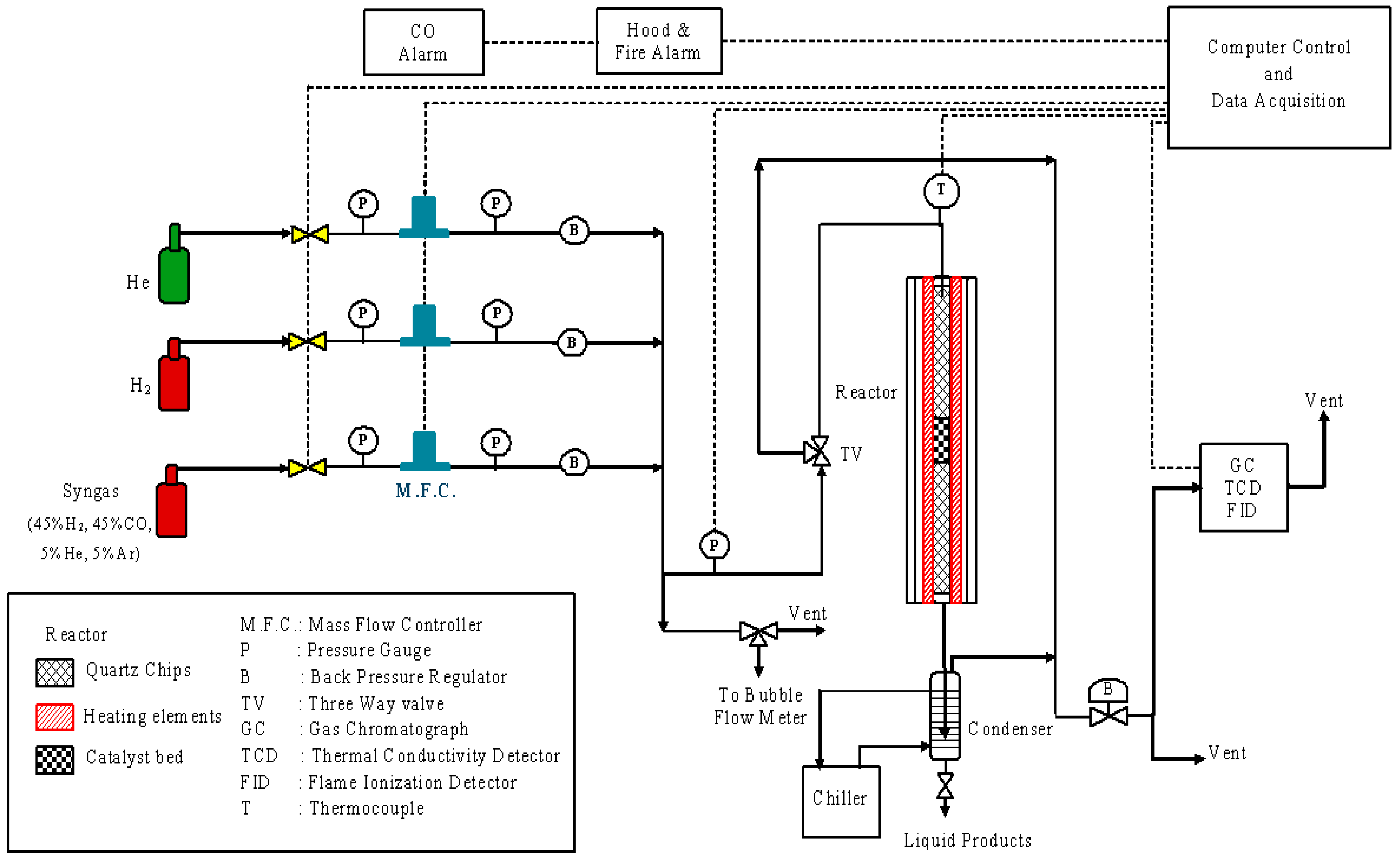
2.2. Reaction Equipment

A schematic of the reactor set-up is shown in Figure 1, similar to that used by Karre et al. [19]. The reactor, located inside of a fume hood, is computer-controlled by the software InTouch, designed by Wonderware. All reactor parameters, except for the reactor pressure, are controlled directly from the computer. The reactor pressure can be manually adjusted using a downstream back-pressure regulator (“B” in Figure 1). The reactor feed gas can be syngas, (nominally) pure H2, or (nominally) pure He. The syngas contains equimolar amounts of CO and H2, along with 5% He and 5% Ar used as internal standards. The pure H2 stream is used during the catalyst activation. The He gas is used for heating and cooling the reactor between pretreatments and processing. The flow rate for each stream is controlled by a separate Brooks 5850E mass-flow-controller (“MFC”) (Sierra, Monterey, CA, USA) that has an operating range of 0–200 cc/min. Omega Engineering pressure gauges “P”, each with an operating range of 0–20,684 KPa, are also used as shown. The reactor product stream goes to a chiller that is maintained at 10 °C during the reactions. The condensed liquid from the chiller is collected in a chiller-pot and removed at fixed intervals for analysis using an isolation valve. The liquid samples are analyzed by a Varian gas chromatograph (GC) (LabX, Midland, ON, Canada) with a flame ionization detector (FID), both not shown in Figure 1. The uncondensed gas from the chiller is routed to a Perkin-Elmer GC (PerkinElmer, Waltham, MA, USA), which is equipped with a thermal conductivity detector (TCD) and FID. The gas is eventually safely vented through the fume hood. The back-pressure regulator upstream of the GC maintains the pressure in the reactor system.
The reactor is a stainless-steel (SS 304L) tube with specifications of 12.7 mm O.D. × 11.46 mm I.D. × 635 mm L, obtained from TW Metals, Inc (Exton, PA, USA). The reactor is heated by a 457 mm single-zone furnace obtained from Applied Test Systems (Butler, PA, USA). Swagelok fittings (Solon, OH, USA) are used where needed in the experimental setup. An ungrounded Inconel sheath K-type thermocouple (model KQSS-116-18, Omega, Norwalk, CT, USA) with 1.5875 mm D × 457.2 mm L specifications is used to measure the catalyst bed temperature.

2.3. Experimental Procedure

All of the nine catalyst samples shown in Table 2 were tested separately for FTS in the set-up of Figure 1. A single temperature and pressure were used for all runs. The values for these parameters were selected as follows. The high-temperature FT process (HTFT), which operates at 300–345 °C, relies on iron-based catalysts [20]. The chain length of the product molecules is controlled by the reaction temperature [21]. With an iron-based catalyst, increasing temperature favors a reduction in the chain length of the product molecules [22]. Since the goal of the research is to produce kerosene and gasoline-ranged hydrocarbons, the temperature of 300 °C was chosen to be consistent with other researchers [20,23].
Higher CO conversion rates and a high yield of long-chain alkanes can be obtained with increasing the pressure. Even higher pressures would be favorable, but the benefits may not justify the additional costs of high-pressure equipment [21]. Typical pressures range from 101 to 2634 KPa [20]. An operating pressure of 2068 KPa is chosen to be consistent with other researchers [23,24].
The catalyst bed consisted of 1 g of the catalyst and 4 g of 0.8 mm quartz chips, mixed together and then placed in the center of the reactor. Quartz chips of size 1.6 mm were added upstream and downstream of the catalyst bed as a filler material to avoid any movement of the catalyst bed. A thermocouple was placed such that the tip was at the center of the catalyst bed for accurate temperature measurements.
Before each reaction, the system was pressure-tested with He gas to 2413 KPa (gauge) for safety reasons. The catalyst was then pretreated with pure H2 at 101.325 KPa and 400 °C for 12 h. After this pretreatment, the reactor was cooled to 200 °C using pure He, and then a pressure of 2068 KPa (gauge) was established with He. At that point, the He gas was cut off, syngas was introduced, and the GCs were activated. The temperature of the reaction was increased to 300 °C from 200 °C using pre-programmed software. The reaction temperature and gas flow rates were controlled by the software at the desired value.
The Perkin-Elmer GC (PerkinElmer, Waltham, MA, USA) analyzed the uncondensed gases each hour in the chiller. A liquid sample was also taken from the chiller-pot every 24 h. The liquid sample was separated by decanting and manual separation into an organic phase (hydrocarbons, lighter molecules) and an aqueous phase (water and oxygenates, heavier molecules). These were then analyzed by the Varian GC, not shown in Figure 1. Cyclohexanol was added to the aqueous phase, and carbon disulfide (CS2) to the organic phase as internal standards.
Liquid sample analyses were available for the periods 0–24, 24–48, and 48–72 h. Only the 24–48 h samples are reported here. We excluded the first 24 h because the catalyst would be unstable as iron carbide phases would be forming. We excluded the final 24 h to minimize the effect of any catalyst deactivation.

2.4. Characterization Equipment

The catalyst samples were characterized by pore volume, surface area, elemental analysis, the active phase of the metals, and temperature-programmed hydrogen reduction. Surface area and pore volume distribution were measured using Micromeritics Accelerated Surface Area and Porosimeter System (ASAP) 2020. The quantities of the inorganic elements were analyzed by Inductively Coupled Plasma Optical Emission Spectroscopy (ICP-OES, Vista Pro Model, Varian Inc., Palo Alto, CA, USA). Energy-dispersive X-ray spectroscopy (EDS/EDX) was used for elemental analysis with a Hitachi S-4700 scanning electron microscope (SEM) (Hitachi, Clarksburg, MD, USA) at a high voltage of 10 kV. Temperature-programmed reduction (TPR) measurements used a Micromeritics AutoChem 2950 HP microreactor (Micrometrics, Norcross, GA, USA).

3. Results and Discussion

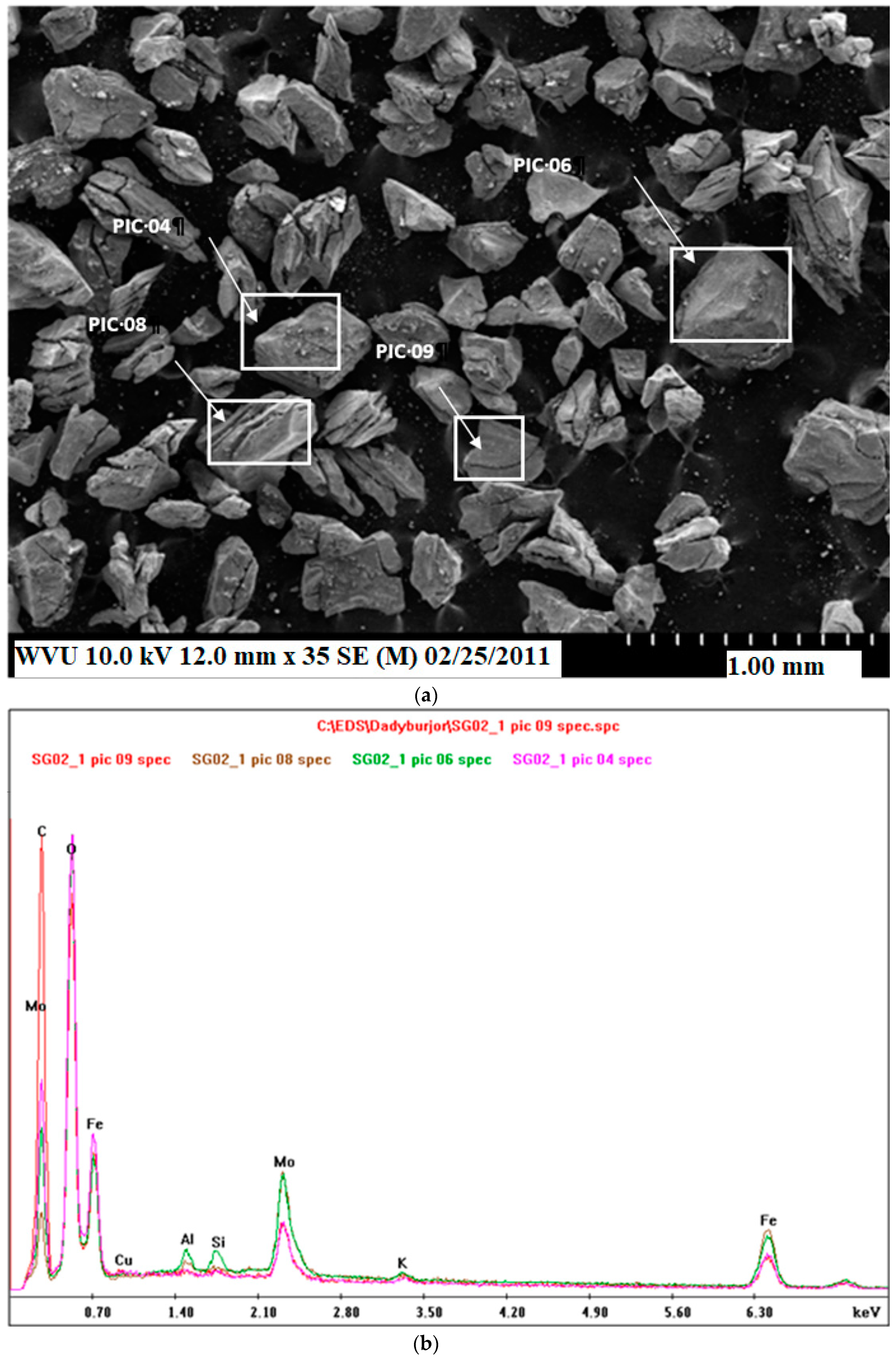
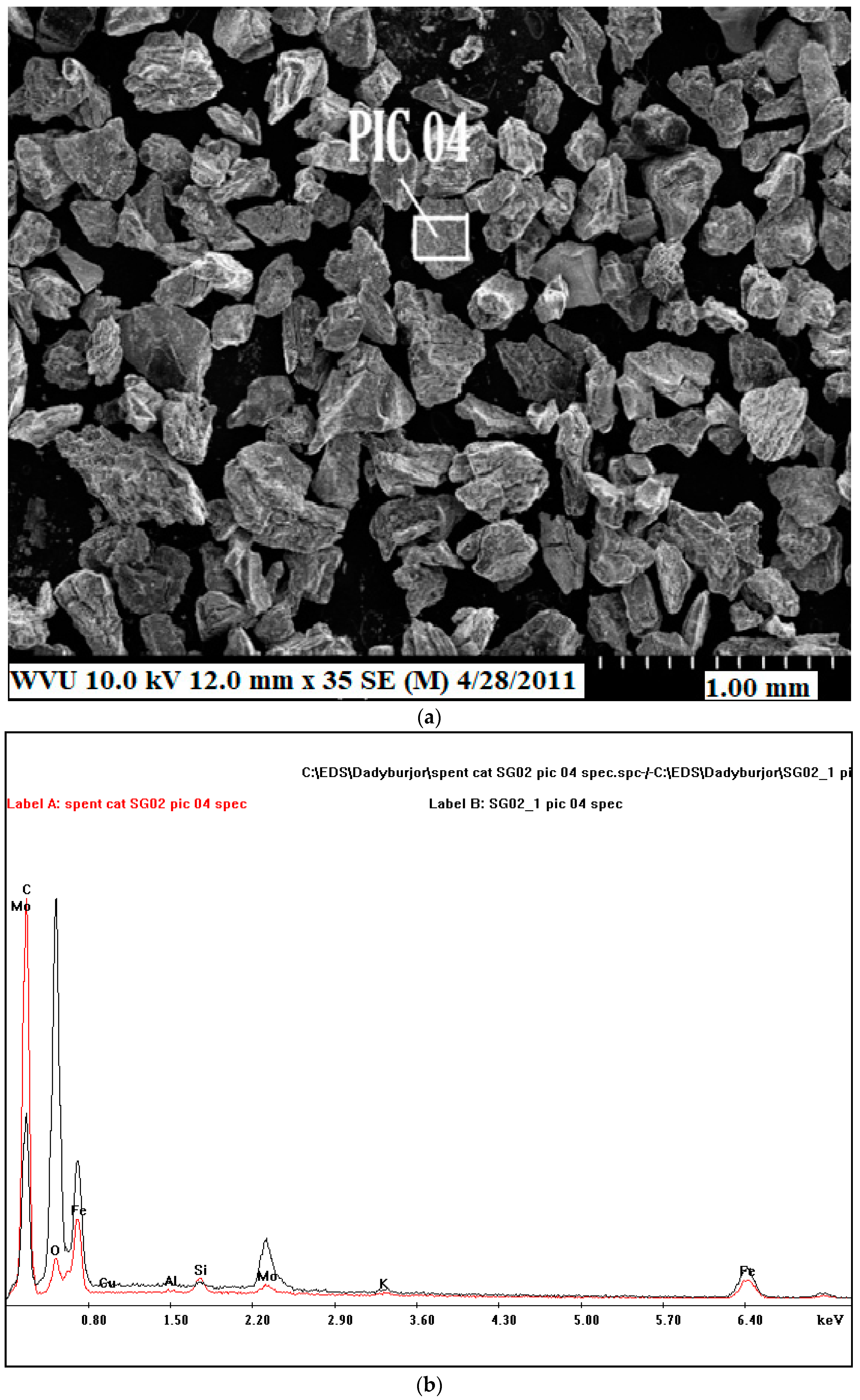
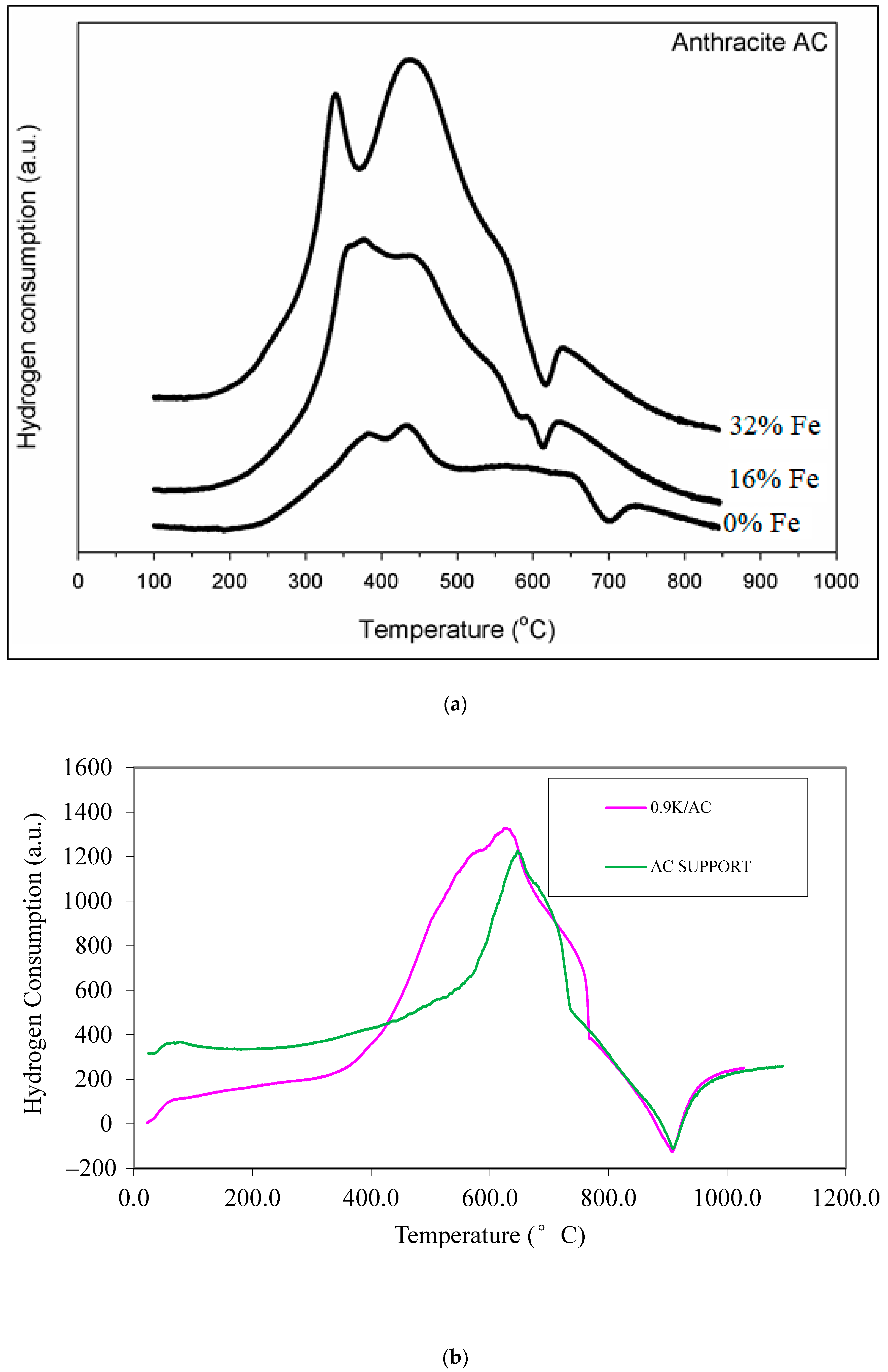
3.1. Catalyst Characterization

The results of the analysis of trace elements in the anthracite-based AC sample by ICP-OES are shown in Table 3 [14]. Elements present in the largest amounts are S (0.45 wt%) and Al (0.24 wt%), with others being one or more orders of magnitude smaller.
The Brunauer, Emmett, and Teller (BET) surface area and the pore volume of the activated carbon support and the baseline catalyst (Sample 1 of Table 2) before and after FTS reactions are shown in Table 4. The surface area and the total pore volume for the fresh baseline catalyst are lower than the respective values of the AC support due to the addition of Fe, Mo, Cu, and K. The decrease is due to the metals filling the micropores and macropores of the AC. Table 4 also contains analogous data for the spent baseline catalyst, after reaction at 300 °C and 2068 KPa for 72 h. The surface area of the spent catalyst decreases by 85% and the pore volume decreases by 90%, both relative to the respective values of the fresh catalyst. This decrease could be due to either the spent catalyst being partially collapsed after FTS or the FTS products remaining in the pores of the catalyst.
Figure 2a and Figure 3a show the surface morphology of the fresh and spent baseline catalysts, respectively, using SEM. The darker areas are richer in AC, and the lighter areas are richer in metals. The areas denoted by white squares are magnified and scanned by EDX in Figure 2b and Figure 3b. The Fe, Mo, K, and Cu peaks in the EDX scans confirm the metal coatings for fresh as well as spent catalysts. Note that the peak areas in Figure 2b of the same element in different white squares of Figure 2a appear to be almost the same, with the small differences in the peaks for each element possibly due to non-uniformity in impregnation. Reduced peaks of the metals in the spent catalyst relative to the fresh sample (Figure 3b relative to Figure 2b) could be due to coking of the fresh catalyst after 72 h reaction time. This is consistent with the BET results mentioned earlier.
TPR results for Samples 1–3, with varying amounts of Fe, are shown in Figure 4a. The peaks at 370–550 °C suggest that all the oxide phases undergo a slow, simultaneous reduction. The hydrogen consumption for 32% Fe catalyst (Sample 2) is the highest, due to the higher iron loading than the other two catalysts.
As mentioned earlier, other materials were also subjected to TPR. Figure 4b shows the TPR profiles of the AC support and 0.9K/AC. Note that the 0.9K/AC material was not used in the reactor (not mentioned in Table 2). It is used here to note the reduction potential of only K in the absence of any other metals. Figure 4b indicates that K2O is not reduced but, as seen from the higher hydrogen consumption when K is added to AC, the K2O promotes the reduction of the AC support, probably due to electronic effects.
Figure 4c shows TPR profiles of the AC support, 16Fe/AC, 16Fe0.9K/AC, and 16Fe1.8K/AC. Again, the 16Fe/AC, 16Fe0.9K/AC, and 16Fe1.8K/AC samples were prepared only to see the reduction potential of K in the presence of Fe without other promoters. Figure 4c shows that K suppresses the reduction of iron oxides. This suggests that a strong interaction exists between K and Fe oxides.
Figure 4d shows TPR profiles of the AC support, 16Fe/AC, 16Fe6Mo/AC, 16Fe6Mo0.8Cu/AC, and 16Fe6Mo0.9K/AC. As in Figure 4c, the 16Fe/AC and 16Fe6Mo/AC samples were prepared only to see the reduction potential of Mo in the presence of Fe without other promoters. The other two samples are identical to Samples 5 and 9 of Table 2. The curves of Figure 4d indicate that Mo and K suppress the reduction of iron oxides. Additionally, from Figure 4d, the hydrogen consumption is generally higher for 16Fe6Mo0.8Cu/AC than for the other materials mentioned. This indicates that Cu greatly promotes the reduction of iron oxides, thereby suggesting that a strong interaction exists for elements Cu, Mo, and K with Fe oxides.

3.2. Reaction Results

GC results from each reaction could be quantified because of the use of internal standards in the liquid- and vapor-phase products, as mentioned earlier. These results characterize the output of each product in the outlet stream. For simplicity, many of the products are lumped together to describe the reaction results, e.g., C2–4 hydrocarbons in the vapor phase. Using these lumps, performance parameters were defined for each of the nine catalysts of Table 2. The parameters reported are CO conversion (X), CO2 selectivity (SCO2), H2/CO usage ratio (U), hydrocarbon production (PHC), alcohol production (POH), total oil-phase liquid weight (WO), total aqueous-phase liquid weight (WAQ), alcohol selectivity (SOH), the selectivity of hydrocarbon lumps Y (SY, where the parameters are obtained separately for Y equal to CH4 and the lumps C2–4, C5+, C6–8, and C9–15), olefin-to-paraffin ratios for hydrocarbon lumps Z (OPZ, where the parameters are obtained separately for Z equal to the lumps C2–4 and C6–14, respectively), and distribution of alcohol A(DA), where A refers to methanol through pentanol. These terms are defined as:
CO   conversion   ( X ,   % ) = molar   flow   rate   of   CO   consumption molar   flow   rate   of   CO   inlet × 100
CO 2   selectivity   ( S CO 2 ,   % ) = molar   flow   rate   of   CO 2   produced molar   flow   rate   of   CO 2   consumed × 100
H 2 / CO   usage   ratio   ( U ) = molar   ratio   of   H 2   consumption molar   ratio   of   CO   consumption
Hydrocarbon   productivity   ( P HC ,   g / kg-cat-h ) = total   hydrocarbon   production   rate mass   of   catalyst
Alcohol   productivity   ( P OH ,   g / kg-cat-h ) = total   alcohol   production   rate mass   of   catalyst
Alcohol   selectivity   ( S OH ,   % ) = production   rate   of   total   alcohols production   rate   of   alcohols + production   rate   of   hydrocarbons × 100
Selectivity   of   hydrocarbon   Y   ( S Y ,   % ) = rate   of   hydrocarbon   Y rate   of   hydrocarbons   produced × 100
Olefin-to-paraffin   ratio   ( OP Z ) = production   rate   of   olefin   Z production   rate   of   paraffin   Z
Alcohol   distribution   ( D A ,   % ) = weight   of   alcohol   A total   weight   of   all   alcohols × 100

3.2.1. Effect of Varying Fe Composition on FTS Activity

Table 5 shows the results on FTS performance of varying Fe compositions (with Mo, K, and Cu amounts held constant) using Samples 1–3. The performance parameters are defined in Equations (5) to (13).
There is no measurable FTS activity at 0% Fe. The addition of 32% Fe shows improvement in both X and SCO2 compared to the values for 16% Fe. The higher SCO2 value for the 32% Fe sample suggests higher WGS activity and more active sites for WGS. The values of U are lowered with Fe addition, also implying higher WGS activity.
Increasing the Fe addition from 16% to 32% does not increase PHC appreciably. This may be due to excess Fe loading in AC pores. Hence, an optimal amount of Fe is required to achieve the highest FTS and WGS activities.
All values of OP decrease with the addition of Fe past 16%. This is perhaps because straight-chained hydrocarbon molecules are more favored with additional Fe-based active sites, since FT reactions are governed by polymerization kinetics [25].
As mentioned above, no hydrocarbons are formed at 0% Fe loading. This is due to the absence of FTS active sites or iron carbide phases; no active sites are available (except for the negligible amount of Fe in the anthracite-based AC support). From Table 5, with Fe addition past 16%, values of SCH4 and SC5–C15 increase slightly, while SC2–C4 decreases slightly. This may be due to additional FTS active sites promoting the polymerization of small-chain hydrocarbons, C2–C4, to C5+ hydrocarbons. This is consistent with the study by Tavasoli et al. [26]. Similar research was conducted by Ma et al. [27] where Fe-based catalysts are rapidly poisoned by all sulfur-containing compounds, as these compounds withdraw electrons from the catalyst surface. Ma et al. [27] also reported lower product selectivities due to sulfur poisoning.
As noted earlier, alcohol is not measured at 0%Fe loading due to the absence of FTS active sites. In the other two Fe loadings, the value of POH is very small compared to that of hydrocarbons, PHC. The values of SOH are very low for the alcohols that can be individually measured, but for these low-molecular weight alcohols, SOH appears to increase slightly with Fe addition, perhaps due to an increased amount of iron-carbide phase. As shown in Table 6, ethanol is the dominant product in both Fe-containing catalysts, followed by methanol, butanol, propanol, and then pentanol. This sequence matches the earlier reports from our laboratory [6]. As pentanol is a bulky molecule compared with other alcohols, formation and desorption reactions are perhaps not favored inside the AC pores. The percentage of ethanol formed is maximum at 16% Fe and decreases with further Fe loading.
These results suggest that 16% Fe is the best loading of the three. Clearly, Fe is needed for the catalyst, but the available pore volume in the AC may be blocked by the excessive loading of 32% Fe, consistent with results obtained for the 16% Fe catalyst. Iron is an essential element for FTS WGS reactions, and the catalyst activity is mainly because of the iron carbide phase.

3.2.2. Effect of Varying K Composition on FTS Activity

Table 7 shows the performance parameters for Samples 1, 4, and 5, i.e., varying K compositions with other promoters and Fe held constant. Values of X, PHC, and OP are all higher for 0.9% K than for 0% K or 1.8% K, while values of POH and WAQ show the opposite trend. This is perhaps due to stronger CO and H2 adsorption on the catalyst surface in the presence of small amounts of K. There is a slight improvement in PHC with a small addition of K. The values of U and SCO2 are approximately constant with K addition, suggesting that K does not participate in WGS, in contrast to Fe.
The values of SCH4 and SC2–4 decrease while SC5+ increases with the addition of K. These results are consistent with findings in the literature [3,6,11,28]. K could be helping CH4 and C2–4 molecules to react with other intermediate products or with each other through FTS reactions to form higher molecular weight compounds.
The values of POH are very small compared to the corresponding ones of hydrocarbons, PHC. When increasing the K addition from 0.9% to 1.8%, the value of PHC is decreased. The value of SOH is approximately three times larger when K loading is doubled, which is consistent with findings by Ma et al. [6]. Table 6 also shows that ethanol is the dominant product, followed by methanol, propanol, butanol, and pentanol. These findings also match the reports by Ma et al. [6].
In general, a small amount of K increases FTS activity, but larger amounts decrease FTS activity. Larger amounts of K could be either blocking the iron-carbide phase of the catalyst or blocking the AC pores due to excessive loading. Hence, the loading of 0.9 wt% K appears to be the best of the three.
Finally, we note that it is well-known that K catalyzes the high-temperature pyrolysis and the steam gasification of coal, coal-like substances, and carbonaceous matrices. Yet, note that these processes occur at high temperatures—800 °C and above [29]. This is significantly higher than the temperatures used in this work (around 300 °C), or in commercial FTS. Therefore, it is reasonable to assume that the K impregnated in the anthracite-based AC sample used in this research did not take part in any gasification-type reactions.

3.2.3. Effect of Varying Mo Composition on FTS Activity

Table 8 shows the results for Samples 1, 6, and 7, i.e., varying Mo compositions with other promoters and Fe held constant.
No appreciable amounts of hydrocarbon or oxygenate products are formed at 0% Mo (Sample 7). This is noteworthy because Sample 7 contains Fe, which is an FTS catalyst. The runs were repeated, with the same results. Examining the details of the run indicates that the CO conversion and other parameters are small but non-zero at the first data point (6 h time on stream) but decay rapidly to zero before the time period used in Table 8 (24–48 h time on stream). Similar runs, but with a commercial AC support (Norit SX Ultra) yielded the expected number of FT products. (To be consistent, the results at 6 h TOS, and those with the commercial support are not included in Table 8.) Hence, it is likely that the anthracite-based AC support used here interacts with the other catalytic metals in the absence of Mo, resulting in a rapidly deactivating and poorly active FT catalyst. Table 3 indicates that the AC used here contains relatively large amounts of S, which is not expected to be present in the peat-based Norit AC which is conventionally used. For the anthracite-based AC support, irreversible poisoning due to sulfur could be deactivating the Fe-based catalyst [27], as sulfur withdraws electrons from the catalyst surface. Even small quantities of Mo could interfere with sulfur poisoning of the Fe catalyst, effectively improving the stability of the catalyst.
With the addition of 6% Mo, there is a major improvement in X and SCO2 and a consequent decrease in U. A higher SCO2 (and lower U) suggests higher WGS activity and therefore, more available WGS active sites.
As before, the POH is small compared to the hydrocarbons. The overall SOH is low, but appears to increase slightly with Mo addition.
The value of PHC increases with a small amount of Mo, but a further increase to 12% decreases the value. This suggests that the available pore volume in the AC may be blocked by the excessive loading of 12% Mo. At the highest Mo loading, PHC and POH decrease but SOH increases, i.e., alcohols decrease proportionately less than hydrocarbons. Similarly, SC5+ increases at the expense of C4 and lighter hydrocarbons. The value of OPC6-14 decreases slightly with Mo loading, presumably because the straight-chained hydrocarbon molecules are favored. These results with increase in Mo are consistent with previous reports by others [30].
From Table 6, it can be seen that ethanol is the dominant product in both catalysts, followed by methanol, propanol, butanol, and pentanol. This sequence matches reports by Ma et al. [6]. The distribution of alcohols was not measured at 0%Mo loading, as no appreciable product was formed, as seen by the lower productivity values in Table 8. The values of DA for the lower-molecular-weight alcohols increase at 6% Mo and decrease with further Mo loading. The decrease in values of DA at a higher Mo loading is probably due to a decrease in available pore volume in the AC for the reactions.
Hence, the best of the three Mo loadings would seem to be 6 wt%. The better results with the intermediate value could be due to the reduced pore volume of the excessive metal loaded catalyst.

3.2.4. Effect of Varying Cu Composition on FTS Activity

Table 9 shows results using Samples 1, 8, and 9, i.e., varying Cu composition with other promoters and Fe held constant. The catalyst without any Cu shows a slightly lower value of × when compared to those of the promoted catalyst. The value of × increases by approximately 4% with a small addition of Cu (i.e., for the baseline catalyst), but drops somewhat with further loading of Cu. The SCO2 (indicative of WGS activity) increases slightly but monotonically with an increase in Cu loading. This is perhaps due to stronger CO and H2 adsorption on the catalyst surface in the presence of small amounts of Cu. These results are consistent with several studies in the literature [3,8]. The baseline catalyst shows the highest values of PHC and OP. With an increase in Cu loading, SCH4 and SC2–4 increase, and correspondingly values of SC5+, SC6–C8, and SC9–C15 drop. This means that Cu is shifting the product profile towards the lighter molecules, consistent with the literature [12].
As shown in Table 6, ethanol is the dominant product in all the catalysts, followed by methanol, propanol, butanol, and pentanol. The sequence also matches the reports by Ma et al. [6].

4. Summary and Conclusions

The paper shows novelty by studying the effect and variation of Fe, Cu, K, and Mo supported on an AC support made from North American-based anthracite on the selectivity and productivity of different hydrocarbons and alcohols. The research presented shows a significant research gap which could be used to produce clean hydrocarbons. This research studies nine data points with varying different metals. The results from this research significantly add to the knowledge of Fe-based FT catalysts and could be used to further develop the catalyst.
CO conversion and CO2 selectivity increase when the amount of Fe increases, which means that FTS activity and WGS activity both increase. A small increase in C1 selectivity is observed with an increase in Fe loading, but C2–C4 selectivity decreases. The selectivity of C6–C15 hydrocarbons increases with Fe loading due to more available FTS active sites. Alcohol production does not increase significantly with Fe loading, and hydrocarbon production increases only slightly. This would seem to suggest that Fe-based catalysts favor the production of hydrocarbons. Based on these results, 16% Fe loading is found to be the best of the three values used.
A small amount of K increases FTS activity, but larger amounts result in a decrease. The alcohol selectivity increases when K loading is increased. The selectivity of C1–C4 decreases with addition of K, but the selectivity of C6–C8 hydrocarbons increases. A small amount of K increases the formation of primary olefins, while larger amounts of K have a smaller effect. Based on these results, 0.9% K loading is found to be the optimum composition.
No appreciable FTS products occur at 0% Mo, as seen by the lower CO conversion. This is probably because of the interaction of the Fe and other metals with S in the AC support in the absence of Mo. With the addition of 6% Mo, CO conversion and CO2 selectivity increase, which suggests higher WGS activity due to more available active sites on the catalyst. Hydrocarbon productivity decreases with a further increase in Mo loading, suggesting that 6% Mo is the best loading of the three. Straight-chain hydrocarbon molecules are favored with an increase in Mo loading. The methane selectivity and C5+ hydrocarbon selectivity both increase with an increase in Mo loading.
In comparison to the other metals, very small effects are observed for all parameters with an increase in Cu loading. In response to an increase in Cu loading, a slight increase in the selectivity of C1–C4 and a slight decrease in the selectivity of both C5+ and C6–C15 are observed. Based on these results, 0.8% Cu loading is found to be the best of the three values used.

Author Contributions

Conceptualization, D.B.D.; methodology, S.J.G., A.V.K., A.K.; software, A.K.; validation, S.J.G., A.K.; formal analysis, S.J.G., A.V.K., A.K.; investigation, S.J.G., A.V.K.; resources, S.J.G.; data curation, S.J.G.; writing—original draft preparation, A.V.K., S.J.G.; writing—review and editing, S.J.G., A.V.K., A.K., D.B.D..; visualization, S.J.G.; supervision, D.B.D.; project administration, A.K.; funding acquisition, D.B.D. All authors have read and agreed to the published version of the manuscript.

Funding

This study was supported by the U.S. Department of Energy under a Cooperative Agreement DE-FC26-05NT42456 with the Consortium for Fossil Fuel Science (CFFS).

Acknowledgments

This study was supported by the U.S. Department of Energy under a Cooperative Agreement DE-FC26-05NT42456 with the Consortium for Fossil Fuel Science (CFFS). The funding source played no role in the study’s design; in the collection, analysis and interpretation of the data; in report writing; or in publication decisions. We like to thank Wenping Ma for providing TPR data for 0.9K/AC, 16Fe/AC, 16Fe0.9K/AC, 16Fe1.8K/AC, and 16Fe6Mo/AC.

Conflicts of Interest

The authors declare no conflict of interest. The funding source played no role in the study’s design; in the collection, analysis and interpretation of the data; in report writing; or in publication decisions

References

  1. Yang, Y.; Xiang, H.; Tian, L.; Wang, H.; Zhang, C.; Tao, Z.; Xu, Y.; Zhong, B.; Li, Y. Structure and Fischer–Tropsch performance of iron–manganese catalyst incorporated with SiO2. Appl. Catal. A Gen. 2005, 284, 105–122. [Google Scholar] [CrossRef]
  2. Davis, B.H. Fischer-Tropsch synthesis: Relationship between iron catalyst composition and process variables. Catal. Today 2003, 84, 83–98. [Google Scholar] [CrossRef]
  3. Bukur, D.B.; Mukesh, D.; Patel, S.A. Promoter effects on precipitated iron catalysts for Fischer-Tropsch synthesis. Ind. Eng. Chem. Res. 1990, 29, 194–204. [Google Scholar] [CrossRef]
  4. Ma, W.P.; Ding, Y.J.; Lin, L.W. Fischer–Tropsch Synthesis over Activated-Carbon-Supported Cobalt Catalysts: Effect of Co Loading and Promoters on Catalyst Performance. Ind. Eng. Chem. Res. 2004, 43, 2391–2398. [Google Scholar] [CrossRef]
  5. Kugler, E.L.; Feng, L.; Li, X.; Dadyburjor, D.B. Effect of Ni on K-doped molybdenum-on-carbon catalysts: Temperature-programmed reduction and reactivity to higher-alcohol formation. Stud. Surf. Sci. Catal. 2000, 130, 299–304. [Google Scholar]
  6. Ma, W.; Kugler, E.L.; Dadyburjor, D.B. Effect of Mo loading and support type on hydrocarbons and oxygenates produced over Fe-Mo-Cu-K catalysts supported on activated carbons. Stud. Surf. Sci. Catal. 2007, 163, 125–140. [Google Scholar]
  7. Ribeiro, M.C.; Jacobs, G.; Davis, B.H.; Cronauer, D.C.; Kropf, A.J.; Marshall, C.L. Fischer–Tropsch synthesis: An in-situ TPR-EXAFS/XANES investigation of the influence of group I alkali promoters on the local atomic and electronic structure of carburized Iron/Silica catalysts. J. Phys. Chem. C 2010, 114, 7895–7903. [Google Scholar] [CrossRef]
  8. Chernavskii, P.A.; Kazak, V.O.; Pankina, G.V.; Perfiliev, Y.D.; Li, T.; Virginie, M.; Khodakov, A.Y. Influence of copper and potassium on the structure and carbidisation of supported iron catalysts for Fischer-Tropsch synthesis. Catal. Sci. Technol. 2017, 7, 2325–2334. [Google Scholar] [CrossRef]
  9. Yang, Y.; Xiang, H.W.; Xu, Y.Y.; Bai, L.; Li, Y.W. Effect of potassium promoter on precipitated iron-manganese catalyst for Fischer–Tropsch synthesis. Appl. Catal. A Gen. 2004, 266, 181–194. [Google Scholar] [CrossRef]
  10. Li, S.; Krishnamoorthy, S.; Li, A.; Meitzner, G.D.; Iglesia, E. Promoted iron-based catalysts for the Fischer–Tropsch synthesis: Design, synthesis, site densities, and catalytic properties. J. Catal. 2002, 206, 202–217. [Google Scholar] [CrossRef] [Green Version]
  11. Luo, M.; Davis, D.H. Fischer-Tropsch Synthesis: Activation of Low-Alpha Potassium Promoted Iron Catalysts. Fuel Process. Technol. 2003, 83, 49–65. [Google Scholar] [CrossRef]
  12. Wan, H.; Wu, B.; Zhang, C.; Xiang, H.; Li, Y. Promotional effects of Cu and K on precipitated iron-based catalysts for Fischer–Tropsch synthesis. J. Mol. Catal. A Chem. 2008, 283, 33–42. [Google Scholar] [CrossRef]
  13. Lohitharn, N.; Goodwin, J.G. Effect of K promotion of Fe and FeMn Fischer–Tropsch synthesis catalysts: Analysis at the site level using SSITKA. J. Catal. 2008, 260, 7–16. [Google Scholar] [CrossRef]
  14. Gujjar, S.J. Fischer-Tropsch Synthesis for Kerosene-Range Products Using a Multi-Component Catalyst Supported on Coal-Based Activated Carbon. Master’s Thesis, West Virginia University, Morganton, WV, USA, 2011. [Google Scholar]
  15. Karre, A.V.; Kababji, A.; Kugler, E.L.; Dadyburjor, D.B. Effect of addition of zeolite to iron-based activated-carbon-supported catalyst for Fischer–Tropsch synthesis in separate beds and mixed beds. Catal. Today 2012, 198, 280–288. [Google Scholar] [CrossRef]
  16. Sietsma, J.R.; Dillen, A.J.; Jongh, P.E.; Jong, K.P. Application of ordered mesoporous materials as model supports to study catalyst preparation by impregnation and drying. Stud. Surf. Sci. Catal. 2006, 162, 95–102. [Google Scholar]
  17. Ma, W.; Kugler, E.L.; Wright, J.; Dadyburjor, D.B. Mo-Fe catalysts supported on activated carbon for synthesis of liquid fuels by the Fischer-Tropsch process: Effect of Mo addition on reducibility, activity, and hydrocarbon selectivity. Energy Fuels 2006, 20, 2299–2307. [Google Scholar] [CrossRef]
  18. Ma, W.P.; Center for Applied Energy Research, University of Kentucky, Lexington, KY, USA. Personal Communication, 2020.
  19. Karre, A.V.; Kababji, A.; Kugler, E.L.; Dadyburjor, D.B. Effect of time on stream and temperature on upgraded products from Fischer–Tropsch synthesis when zeolite is added to iron-based activated-carbon-supported catalyst. Catal. Today 2013, 214, 82–89. [Google Scholar] [CrossRef]
  20. Makhura, E.; Rakereng, J.; Rapoo, O.; Danha, G. Effect of the operation parameters on the Fischer Tropsch synthesis process using different reactors. Procedia Manuf. 2019, 35, 349–355. [Google Scholar] [CrossRef]
  21. Schulz, H. Major and minor reactions in Fischer-Tropsch synthesis on cobalt. Catal. Top. Catal. 2003, 26, 73–85. [Google Scholar] [CrossRef]
  22. Riedel, T.; Schulz, H.; Schaub, G.; Jun, K.; Hwang, J.; Lee, K. Fischer–Tropsch on iron with H2/CO and H2/CO2 as synthesis gases: The episodes of formation of the Fischer–Tropsch regime and construction of the catalyst: Fischer-Tropsch catalysis-science and practice. Top. Catal. 2003, 26, 41–54. [Google Scholar] [CrossRef]
  23. Weber, J.L.; del Monte, D.M.; Beerthuis, R.; Dufour, J.; Martos, C.; de Jong, K.P.; de Jongh, P.E. Conversion of synthesis gas to aromatics at medium temperature with a fischer tropsch and ZSM-5 dual catalyst bed. Catal. Today 2020. [Google Scholar] [CrossRef]
  24. Davidson, A.L.; Gibson, E.K.; Cibin, G.; Rensburg, H.V.; Parker, S.F.; Webb, P.B.; Lennon, D. The application of inelastic neutron scattering to investigate iron-based Fischer-Tropsch to olefins catalysis. J. Catal. 2020, 392, 197–208. [Google Scholar] [CrossRef]
  25. Martinez, A.; Rollan, J.; Arribas, M.A.; Cerqueira, H.S.; Costa, A.F.; Aguiar, E.F.S. A detailed study of the activity and deactivation of zeolites in hybrid Co/SiO2-zeolite Fischer–Tropsch catalysts. J. Catal. 2007, 249, 162–173. [Google Scholar] [CrossRef]
  26. Tavasoli, A.; Trépanier, M.; Abbaslou, R.M.M.; Dalai, A.K.; Abatzoglou, N. Fischer–Tropsch synthesis on mono- and bimetallic Co and Fe catalysts supported on carbon nanotubes. Fuel Process. Technol. 2009, 90, 1486–1494. [Google Scholar] [CrossRef]
  27. Ma, W.; Jacobs, G.; Sparks, D.E.; Todic, B.; Bukur, D.B.; Davis, B.H. Quantitative comparison of iron and cobalt based catalysts for the Fischer-Tropsch synthesis under clean and poisoning conditions. Catal. Today 2020, 343, 125–136. [Google Scholar] [CrossRef]
  28. Anderson, R.B. The Fischer-Tropsch Synthesis; Academic Press: London, UK, 1984; pp. 87–89. [Google Scholar]
  29. Dahou, T.; Defoort, F.; Jeguirim, M.; Dupont, C. Towards understanding the role of K during biomass steam gasification. Fuel 2020, 282, 118806. [Google Scholar] [CrossRef]
  30. Qin, S.; Zhanga, C.; Xua, J.; Wua, B.; Xianga, H.; Li, Y. Effect of Mo addition on precipitated Fe catalysts for Fischer–Tropsch synthesis. J. Mol. Catal. A Chem. 2009, 304, 128–134. [Google Scholar] [CrossRef]
Figure 1. Experimental set-up to study the performance of Fischer–Tropsch synthesis.
Reactions 02 00003 g001
Figure 2. (a) Scan at low magnification of the fresh baseline catalyst. (b) EDX comparison spectrum for rectangles marked in the image.
Reactions 02 00003 g002
Figure 3. (a) Scan at low magnification of the spent baseline catalyst. (b) EDX comparison spectrum for spent baseline catalyst.
Reactions 02 00003 g003
Figure 4. (a) Temperature-programmed reduction (TPR) profiles of the Fe-based catalysts with varying Fe composition (Samples 1–3) supported on AC. (b) TPR profiles of the AC support and 0.9K/AC. (c) TPR profiles of the AC support, 16Fe/AC, 16Fe0.9K/AC, and 16Fe1.8K/AC. (d) TPR profiles of the AC support, 16Fe6Mo/AC, 16Fe/AC, 16Fe6Mo0.8Cu/AC, and 16Fe6Mo0.9K/AC.
Reactions 02 00003 g004aReactions 02 00003 g004b
Table 1. Amount of metal salt added per gram of activated carbon (AC).
PromoterSalt UsedComposition (% Metal)Amount of salt (g/gAC)
MoAmmonium Molybdate (NH4)6Mo7O24·4H2O00
60.111
120.222
FeFerric Nitrate Fe(NO3)3·9H2O00
161.157
322.314
CuCupric Nitrate Cu(NO3)2·2.5H2O00
0.80.0293
1.60.058
KPotassium Nitrate KNO300
0.90.0233
1.80.0466
Table 2. Compositions of the Fischer–Tropsch synthesis (FTS) catalyst samples used in this work.
Component wt%
Sample numberFeMoCuK
1 (baseline catalyst)1660.80.9
23260.80.9
3060.80.9
41660.81.8
51660.80
616120.80.9
71600.80.9
81661.60.9
916600.9
Table 3. Trace elemental analysis of activated carbon support.
Element DetectedQuantity, mg/kgElement DetectedQuantity, mg/kgElement DetectedQuantity, mg/kg
Ag31.17Cu16.85S4503.3
Al2433.4Fe493.61Sb9.82
As6.338K309.87Se26.46
B20.98Mg27.33Si571.64
Ba56.79Mn2.54Sn6.76
Be<0.011Mo21.95Sr45
Ca357.84Na178.45Ti109.22
Cd0.814Ni13.65Tl<0.04
Co3.57P95.95V19.36
Cr18.69Pb<0.032Zn6.66
Table 4. Brunauer–Emmett–Teller (BET) measurements of AC support and baseline catalyst (Sample 1).
BET Surface Area, (m2/g)Large-Pore Surface Area, (m2/g)Micropore Volume <2.0 nm (cm3/g)Macropore Volume > 2.0 nm (cm3/g)
Anthracite activated carbon10757420.140.5
Fresh baseline catalyst5914080.0630.225
Spent baseline catalyst1601110.0140.05
Table 5. Performance parameters for varying Fe composition (average taken from the 24–48 h balance). Reaction conditions: 300 °C, 2068 KPa, 1 g cat.
%Fe01632
CO conversion, X (%)34551
CO2 selectivity, SCO2 (%)056.466
H2/CO usage ratio, U1.30.810.79
Hydrocarbon productivity, PHC
(g/kg-cat-h)
0346396
Alcohol productivity, POH
(g/kg-cat-h)
07.218.8
Total oil weight, WO (mg/day)010001720
Total aqueous weight, WAQ (mg/day)04002582
Alcohol overall selectivity, SOH (%)02.04.5
Hydrocarbon selectivity, SY (%) where Y =
CH4018.818.9
C2–C4056.551.5
C5+024.129.7
C6–C8 (liquid)04.18.4
C9–C15 (liquid)07.08.9
Olefin/Paraffin ratio, OPZ, where Z =
C2–C401.841.60
C6–C14 (liquid)00.580.35
Table 6. Effect of Fe, K, Mo, and Cu loading on alcohol distribution (percent of total alcohols). Conditions: 300 °C, 2068 KPa, syngas flowrate 100 sccm/min; 24–48 h, 1 g cat. Base-case composition is 16 Fe, 6 Mo, 0.8 Cu, 0.9 K-AC. Only changes from the base case are shown as catalyst composition below.
Catalyst CompositionMethanolEthanol1-Propanol1-Butanol1-Pentanol
Base case8.419.34.95.10.8
32Fe3.37.03.11.60.5
0Fe00000
1.8 K4.510.32.62.70.4
0 K4.85.72.51.30.5
12Mo4.04.72.11.10.4
0Mo00000
1.6Cu4.28.03.71.10.8
0Cu4.48.74.41.31.0
Table 7. Performance parameters for varying K composition (Average taken from the 24–48 h balance). Reaction conditions: 300 °C, 2068 KPa, 1 g cat.
%K00.91.8
CO conversion, X (%)36.544.530
CO2 selectivity, SCO2 (%)58.556.456.5
H2/CO usage ratio, U0.780.810.83
Hydrocarbon productivity, PHC
(g/kg-cat-h)
336346200
Alcohol productivity, POH
(g/kg-cat-h)
7.677.215.0
Total oil weight, WO (mg/day)20210001000
Total aqueous weight, WAQ (mg/day)11654001500
Alcohol overall selectivity, SOH (%)2.242.06.69
Hydrocarbon selectivity, SY (%) where Y =
CH430.218.813.8
C2–C457.556.552.5
C5+12.224.133.7
C6–C8 (liquid)1.04.113
C9–C15 (liquid)1.37.01.6
Olefin/Paraffin ratio, OPZ, where Z =
C2–C41.051.840.96
C6–C14 (liquid)0.380.580.32
Table 8. Performance parameters for varying Mo composition (Average taken from the 24–48 h balance). Reaction conditions: 300 °C, 2068 KPa, 1 g cat.
%Mo0612
CO conversion, X (%)0.344.510.5
CO2 selectivity, SCO2 (%)056.466
H2/CO usage ratio, U1.250.810.72
Hydrocarbon productivity, PHC
(g/kg-cat-h)
-34665
Alcohol productivity, POH
(g/kg-cat-h)
-7.23.3
Total oil weight, WO (mg/day)01000260
Total aqueous weight, WAQ (mg/day)0400600
Alcohol overall selectivity, SOH (%)-2.04.9
Hydrocarbon selectivity, SY (%) where Y =
CH4-18.822.4
C2–C4-56.547.9
C5+-24.129.7
C6–C8 (liquid)-4.16.4
C9–C15 (liquid)-7.08.8
Olefin/Paraffin ratio, OPZ, where Z =
C2–C4-1.841.84
C6–C14 (liquid)-0.580.38
Table 9. Performance parameters for varying Cu composition (Average taken from the 24–48 h balance). Reaction conditions: 300 °C, 2068 KPa, 1 g cat.
%Cu00.81.6
CO conversion, X (%)40.344.543.2
CO2 selectivity, SCO2 (%)55.856.458.4
H2/CO usage ratio, U0.860.810.81
Hydrocarbon productivity, PHC
(g/kg-cat-h)
278346295
Alcohol productivity, POH
(g/kg-cat-h)
11.327.29.1
Total oil weight, WO (mg/day)10901000480
Total aqueous weight, WAQ (mg/day)12424001100
Alcohol overall selectivity, SOH (%)3.922.03
Hydrocarbon selectivity, SY (%) where Y =
CH41618.820
C2–C45356.559.6
C5+3224.119.9
C6–C8 (liquid)7.14.12.6
C9–C15 (liquid)8.47.03.6
Olefin/Paraffin ratio, OPZ, where Z =
C2–C41.61.841.6
C6–C14 (liquid)0.40.580.38
Publisher’s Note: MDPI stays neutral with regard to jurisdictional claims in published maps and institutional affiliations.

