Article

Fischer–Tropsch Synthesis: Study of Different Carbon Materials as Cobalt Catalyst Support

1
Department of Chemical Engineering, Beijing Institute of Petrochemical Technology, Beijing 102617, China
2
Beijing Key Laboratory of Clean Fuels and Efficient Catalytic Emission Reduction Technology, Beijing 102617, China
3
Department of Chemical Engineering, Beijing University of Chemical Technology, Beijing 100029, China
4
Beijing Academy of Safety Engineering and Technology, 19 Qing-Yuan North Road, Da-Xing District, Beijing 102617, China
5
Department of Chemistry, Eastern Kentucky University, Richmond, KY 40475, USA
*
Authors to whom correspondence should be addressed.
Submission received: 18 December 2020 / Revised: 12 February 2021 / Accepted: 23 February 2021 / Published: 10 March 2021
(This article belongs to the Special Issue Catalytic Conversion of Carbonaceous Materials to Fuels and Chemicals)

Abstract

:

Simple Summary

Cobalt Fischer–Tropsch synthesis catalyst supported on carbon nanotube, activated carbon, graphene oxide, reduced graphene oxide and carbon nanofiber were prepared via impregnation method. TGA, BET, XRD, Raman spectroscopy, TPR, TPD, ICP, SEM and TEM characterization techniques are used to studied the microstructure properties of the catalysts. FT catalyst performance was evaluated in a fixed-bed reactor. The defined three types of carbon materials exhibit superior performance and dispersion compared with graphene oxide and reduced graphene oxide. The thermal stability and pore structure of the five carbon materials vary markedly, and the metal–support interaction is in the order of Co/GO > Co/CNT > Co/AC > Co/CNF > Co/rGO. Among all materials, carbon nanofiber-supported cobalt catalyst showed the best dispersion, the highest CO conversion, and the lowest gas product but the highest heavy hydrocarbons (C5+) selectivity, which can be attributed to the intrinsic property of CNF material that can affect the catalytic performance in a complicated way. This work will open up a new gateway for cobalt support catalysts on various carbon-based materials for Fischer–Tropsch Synthesis.

Abstract

In this work, cobalt Fischer–Tropsch synthesis (FTS) catalyst supported on various carbon materials, i.e., carbon nanotube (CNT), activated carbon (AC), graphene oxide (GO), reduced graphene oxide (rGO), and carbon nanofiber (CNF), were prepared via impregnation method. Based on TGA, nitrogen physisorption, XRD, Raman spectroscopy, H2-TPR, NH3-TPD, ICP, SEM, and TEM characterization, it is confirmed that Co3O4 particles are dispersed uniformly on the supports of carbon nanotube, activated carbon and carbon nanofiber. Furthermore, the FT catalyst performance for as-prepared catalysts was evaluated in a fixed-bed reactor under the condition of H2:CO = 2:1, 5 SL·h−1·g−1, 2.5 MPa, and 210 °C. Interestingly, the defined three types of carbon materials exhibit superior performance and dispersion compared with graphene oxide and reduced graphene oxide. The thermal stability and pore structure of the five carbon materials vary markedly, and H2-TPR result shows that the metal–support interaction is in the order of Co/GO > Co/CNT > Co/AC > Co/CNF > Co/rGO. In brief, the carbon nanofiber-supported cobalt catalyst showed the best dispersion, the highest CO conversion, and the lowest gas product but the highest heavy hydrocarbons (C5+) selectivity, which can be attributed to the intrinsic property of CNF material that can affect the catalytic performance in a complicated way. This work will open up a new gateway for cobalt support catalysts on various carbon-based materials for Fischer–Tropsch Synthesis.

1. Introduction

As a nonrenewable natural resource, petroleum reserve is declining rapidly and it is of great significance to explore an alternative energy utilization pathway [1]. It is well-known, Fischer–Tropsch synthesis (FTS) can convert syngas to liquid fuels and value-added chemicals. As one of today’s clean coal technologies, FTS can provide ultra-clean fuels using coal, natural gas, or biomass [2]. However, the product distribution based on traditional Fischer–Tropsch synthesis catalyst is limited by the ASF (Anderson–Schulz–Flory) principle, and FT product separation is often difficult and cost-ineffective. Therefore, optimizing catalytic performance is vital for academic research and industrial application [3].
Compared with iron-based Fischer–Tropsch catalyst, cobalt-based catalyst exhibits good catalytic activity, higher C5+ selectivity and lower water gas shift (WGS) reaction activity. These properties play an important role in the Fischer–Tropsch synthesis application [4]. Considering its relatively high cost, improving the metallic cobalt utilization efficiency is very important for cobalt-based FT catalysts. Dispersing catalyst metal over the support is an effective way to enlarge its surface area [5]. For supported cobalt catalyst, the reduced crystallite size of the cobalt oxide on the surface of support material can yield enhanced dispersion and the turnover frequency (TOF) of cobalt atom. Cobalt-based Fischer–Tropsch synthesis catalyst exhibits high stability and higher dispersion compared with iron-based catalyst and hence shows excellent overall catalytic performance [6,7].
Generally, traditional FTS catalysts utilize metal oxides (Al2O3, SiO2, or TiO2) as a catalyst support due to their good mechanical stability [8]. However, strong interaction forces between cobalt and the above-defined oxides support makes cobalt oxide difficult to reduce to active metallic cobalt phase, and it thus can, in turn, affect the activity of the catalyst. Remarkably, carbon materials are comparatively inert with weak interaction with cobalt. Therefore, exploring carbon material as a catalyst support could decrease the reduction temperature and improve the catalytic performance. Ahmad Tavasoli et al. [9] studied the carbon-nanotube-supported cobalt catalyst, and explored the influencing factors on catalytic activity, product selectivity, and lifetime. Interestingly, they found that sintering was the key factor leading to the catalyst deactivation. Ma et al. [10] prepared a series of different loading activated carbon-supported cobalt-based catalysts and they found that methane selectivity decreased with reduced cobalt loading. Cheng et al. [11] utilized reduced graphene-oxide-supported iron catalysts to produce lower olefins, and they achieved a high catalytic activity, in terms of FTY (iron time yield to hydrocarbons) at 646 μmol CO ·g(Fe)−1 ·s−1. Guo et al. [12] prepared graphene-supported photocatalytic Fischer–Tropsch synthesis catalyst, which yielded a catalytic activity of 4.4 molCO·mol(Ru)−1·h−1. Bezemer et al. [13] prepared the carbon-nanofiber-supported cobalt-based Fischer–Tropsch synthesis catalyst, and they confirmed that cobalt crystallite size can affect the catalytic activity markedly.
It is widely accepted that the performance of a catalyst is closely related to its morphological properties, chemical composition, as well as its microstructure. So herein, for comparison, different carbon materials, including carbon nanotube, activated carbon, graphene oxide, reduced graphene oxide, and carbon nanofiber, were used to prepare a number of cobalt-based Fischer–Tropsch synthesis catalysts. Adding more, in this work, we systematically studied the support effect on microstructures and FT catalytic performance of the cobalt catalyst. These catalysts were then characterized with differential thermogravimetric analysis (TGA), nitrogen physisorption, X-ray diffraction (XRD), Raman spectroscopy, hydrogen-temperature program reduction (H2-TPR), ammonia-temperature programmed desorption (NH3-TPD), inductively coupled plasma (ICP), scanning electron microscope (SEM), and transmission electron microscope (TEM) to probe the micro-morphology and the physical-chemical properties of the as-prepared catalyst samples. Furthermore, the catalytic performances were also evaluated in a fixed-bed FT reactor to investigate the effect of these carbon materials on thermal stability, morphology features, physical structure, reduction properties, and catalytic performance of the as-synthesized catalysts. In brief, this study is important to expand the application of carbon materials in the FTS field.

2. Experimental

2.1. Catalyst Preparation

Carbon-supported cobalt (15 wt%) Fischer–Tropsch synthesis catalysts were prepared by the impregnation method. In this study, carbon nanotubes were pretreated in concentrated nitric acid (65 wt%) at 140 °C for 14 h. Then the as-obtained mixture was filtered and washed with deionized water to attain the neutral pH level. The filter cake was dried at 120 °C for 12 h, before being ground and sieved to obtain a 60 mesh catalyst sample. The pretreated CNT powders were used as support for cobalt impregnation using cobalt nitrate solution. For this purpose, all the samples were first soaked in cobalt nitrate solution for 24 h before drying at 65 °C on a rotary vacuum evaporator (Rotavapor R-300, Buchi, Swizzled). The as-obtained sample from the Rotavapor flask was further dried in a 120 °C muffle furnace for 12 h and then calcined at 375 °C for 6 h under flowing nitrogen. This carbon nanotube-supported cobalt-based Fischer–Tropsch synthesis catalyst was denoted as Co/CNT.
Similarly, the activated carbon, graphene oxide, reduced graphene oxide, and carbon-nanofiber-supported cobalt Fischer–Tropsch synthesis catalysts were prepared by a similar procedure as used for the synthesis of Co/CNT. However, the activated carbon and graphene oxide were not pretreated with concentrated nitric acid, since concentrated nitric acid pretreatment prevented these two carbon materials from separating from the nitrate acid. In summary, catalysts supported on graphene oxide, carbon nanotube, activated carbon, carbon nanofiber, and reduced graphene oxide were denoted as Co/GO, Co/CNT, Co/AC, Co/CNF, and Co/rGO, respectively.

2.2. Catalyst Characterization

The as-prepared samples were characterized by various physiochemical techniques. The differential thermogravimetric analysis (TGA) of the catalysts was carried out under the air flow at a heating rate of 10 °C/min from 50 to 800 °C on TGA HCT-1 thermal analyzer (Beijing Henven Scientific Instrument Company). Nitrogen physisorption was conducted on BELSORP-max adsorption apparatus (MicrotracBEL, Corp., Japan) at 77 K. Prior to the surface measurement, the sample was degassed under vacuum at 300 °C for 6 h. Surface areas of the calcined catalysts were obtained by Brunauer–Emmett–Teller (BET) technique. Porosity and pore diameter were calculated by Barrett–Joyner–Halenda (BJH) method. Powder X-ray diffraction patterns were recorded on Bruker D8 FOCUS (Bruker Corporation, BILLERICA, MA, USA) using Cu Kα as a radiation source. The diffraction angle of 2θ is scanned in the range of 20–80°, at 40 kV and 30 mA at a scanning rate of 0.02°s−1 per step.
The Raman test of the catalysts was measured on a Confocal Raman Microscope Systems (Renishaw Corporation) with a laser source of 514.5 nm, power of 50 mW, slit width of 50μm. Temperature programmed reduction (TPR) of the catalysts was carried out on Catalyst Analyzer BELCAT-II (MicrotracBEL, Corp., Japan). The catalyst sample was pretreated with argon at 300 °C for 1 h and purge 8.72% H2 in Ar at 30 mL/min. Then the temperature was raised to 800 °C at 10 °C/min and held for 30 min. A thermal conductivity detector was used to record the signal. Temperature programmed desorption (TPD) of the catalysts was carried out in Catalyst Analyzer BELCAT-II (MicrotracBEL, Corp., Japan). For this purpose, the samples were pretreated under argon flow at 550 °C for 1 h and cooled naturally to room temperature. The gas was switched to 10.00% NH3 in He at 30 mL/min for 1 h. Furthermore, the temperature was raised to 800 °C at a rate of 10 °C/min and held for 30 min under He atmosphere. Catalyst bulk elemental composition was analyzed with inductively coupled plasma (ICP) (Optima 2100 DV, Perkin Elmer, Hopkinton, MA, USA). Scanning electron microscope (SEM) images were recorded with XL 30 S-FEG (FEI Corporation, Hillsboro, OR, USA), using a working voltage of 20.0 kV. Transmission electron microscope (TEM) images were obtained with JEM 2010 Electron Microscopy (JEOL Ltd., Japan).

2.3. Fischer–Tropsch Synthesis

The Fischer–Tropsch synthesis test was performed in a stainless fixed-bed tubular reactor with an inner diameter of 12 mm at 210 °C and 2.5 MPa. The reaction mixture of 0.5 g catalyst with 5.0 g of silicon carbide diluent was loaded into the reactor. The catalyst was reduced in-situ in 33 vol% H2 in N2 at 425 °C for 10 h with a space velocity of 5 SL·h−1·g−1. After reduction, the reactor was cooled to 180 °C and H2/N2 gas mixture was switched to syngas (molar ratio of H2: CO = 2:1). The reactor was pressurized to 2.5 MPa under syngas at a space velocity of 5 SL·h−1·g−1 and reheated to 210 °C in 4 h of time span. The gas flow rates were controlled with mass flow controllers (Brooks F29152-008 MFC, Brooks Instrument, Hatfield, PA, USA). The reactor pressure was maintained with a back-pressure regulator (BPR).
Analysis of gas product is performed on on-line gas chromatography equipped with four columns (Agilent 490 Micro Gas Chromatograph, Agilent, Santa Clara, CA, USA). Stabilized catalyst data were collected after passing the 72 h of induction period for the FTS reaction.
The CO conversion rate was calculated using the following equation:
X C O = n i n , C O n o u t , C O n i n , C O × 100 %
where Xco is the CO conversion, nin,CO is the hourly input of CO in moles, nout,CO is the hourly output of CO in moles from the reactor.
Product selectivity was calculated by the following equations:
S C H 4 = n o u t , C H 4 n i n , C O n o u t , C O n o u t , C O 2 × 100 %
S C x ( x = 2 , 3 , 4 ) = x × n c x n i n , C O n o u t , C O n o u t , C O 2 × 100 %
S C 5 + = 1 S C C H 4 S C 2 S C 3 S C 4
where SCH4 is the selectivity of CH4, nout, CH4 is the hourly CH4 output in moles, nin,CO is the hourly input of CO in moles, nout,CO is the output of CO, nout,CO2 is the outlet of CO2 moles, SCx (carbon number x = 2, 3, 4) is C2, C3, and C4 output in moles, and SC5+ is the selectivity of C5+.

3. Results and Discussion

Herin, the physical and reaction properties of the cobalt FTS catalysts supported on various carbon materials, i.e., carbon nanotube (CNT), activated carbon (AC), graphene oxide (GO), reduced graphene oxide (rGO), and carbon nanofiber (CNF), were reported and discussed.

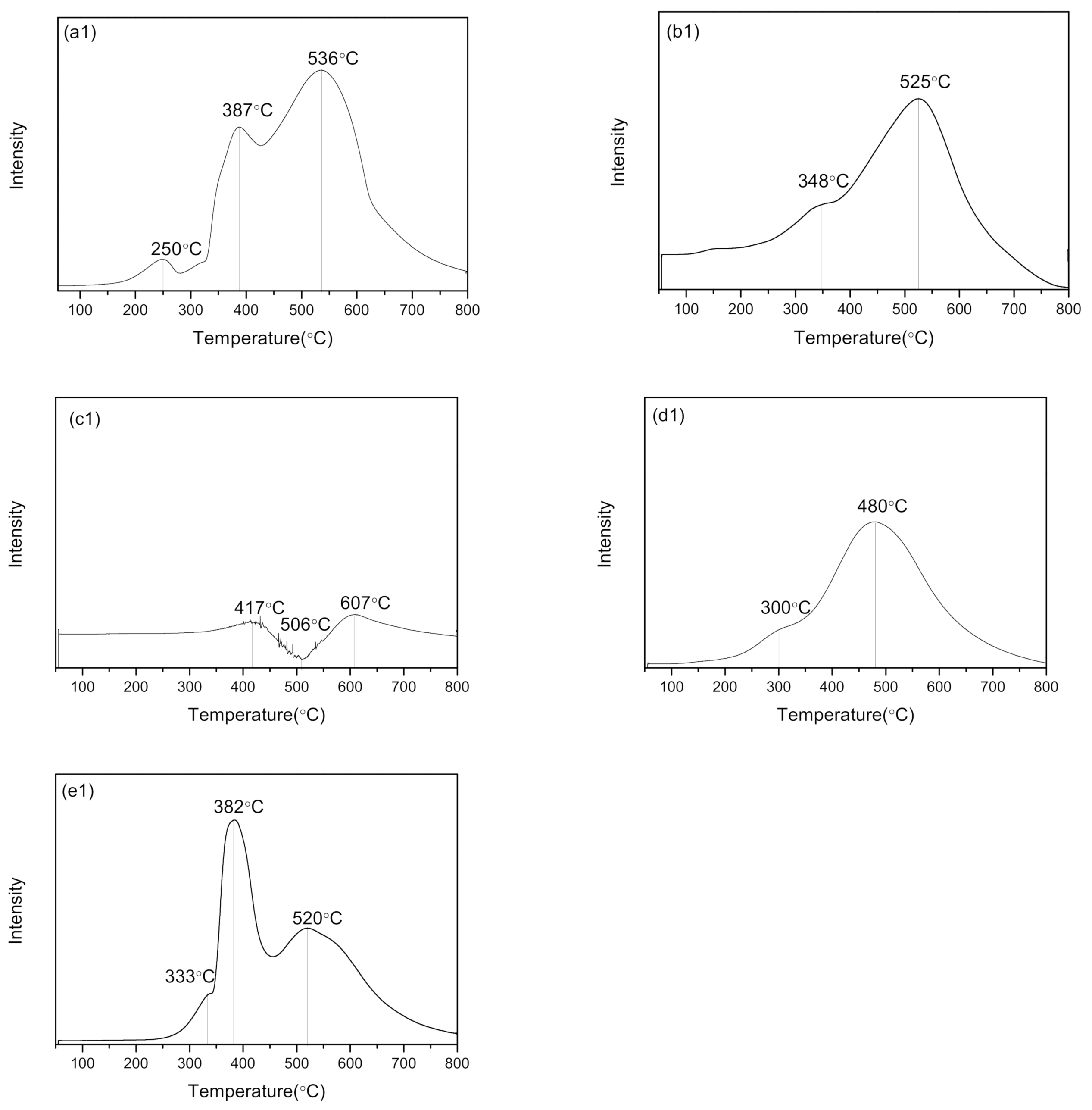
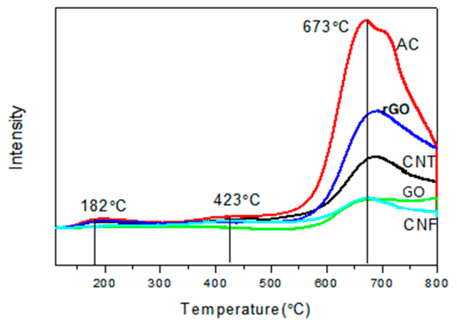
3.1. Thermal Stability Analysis

DTA results for the support carbon materials and the above-mentioned catalyst sample concerned are shown in Figure 1. It can be seen that the thermal stability of the five catalysts and the support materials are likely similar to each other. The decomposition temperatures of the catalysts (217–318 °C) are lower than the corresponding support materials (450–529 °C). The lowered decomposition temperature of the catalyst support is attributed to the addition of the cobalt nitrate. Figure 1(b1) for Co/AC shows a weight loss in the range of 217–512 °C, corresponding to the exothermic peak of the DTA curve. Obviously, the exothermal signal from DTA indicates that the weight losses in all catalyst samples have mainly resulted from the decomposition of catalyst support material [14,15,16].

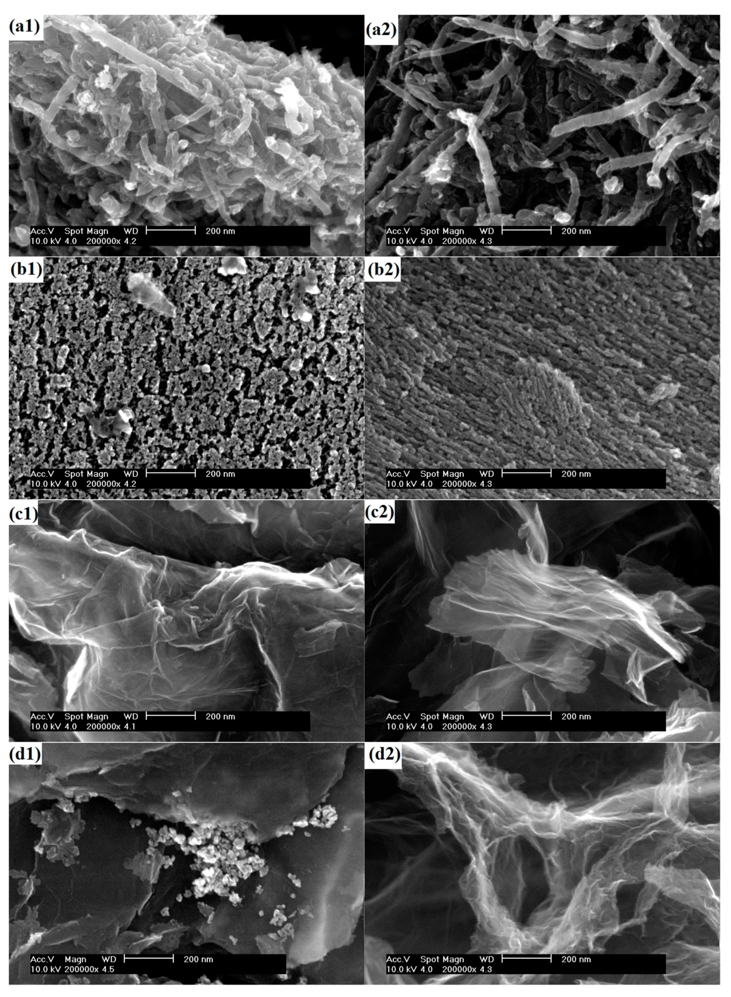
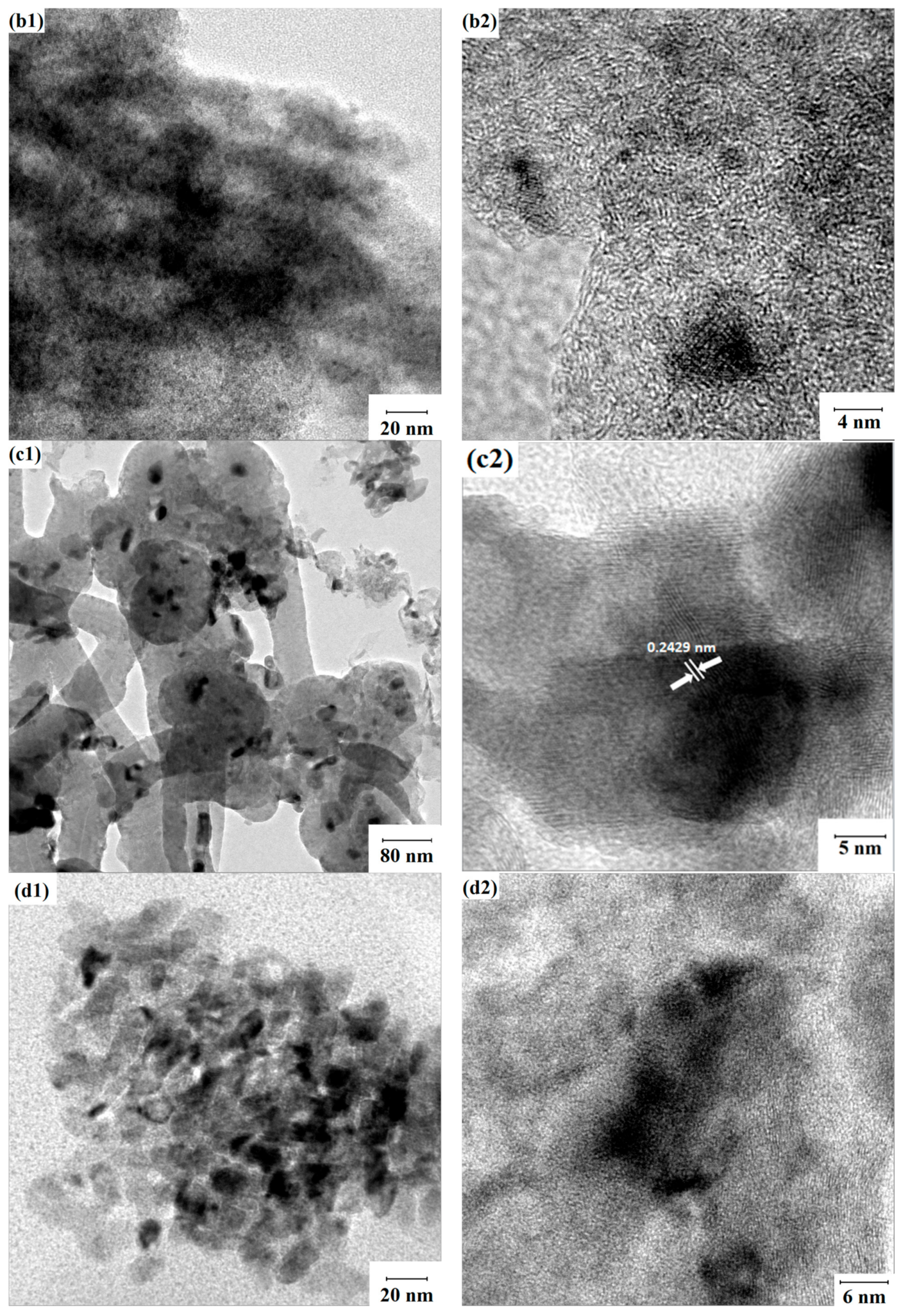
3.2. Morphology of the Catalyst and the Support Materials

The SEM images of the catalysts and the supports are shown in Figure 2. Some particles on the surface of the support in Co/CNT, Co/AC, and Co/CNF catalysts can be clearly seen. As shown in Figure 2(a1) for sample Co/CNT, the cobalt particles distribute uniformly on the carbon nanotube surface, and the particle size is in the range of 10–20 nm. It can be noted that there is no particle observed on the surface of CNT, as shown in Figure 2(a2). In addition, the energy dispersive X-ray analysis (EDX) shown in Figure 3a and suggest that the phase of the particles on the surface of CNT are Co3O4, which is also proved in the XRD, as explained in the late sections. Figure 2(b1) reveals some porous and cracking defects on the surface of the Co/AC catalysts, and this may be due to the sintering in high-temperature calcination process. It can be noticed that very few pores appear on the surface of AC, as shown in Figure 2(b2), while the metal particles on the Co/AC surface were not distributed uniformly. Both large (~97 nm) and small (~35 nm) particles can be observed in Figure 1(b1). From Figure 2(c1), the surface of Co/GO is relatively smooth, only small particles (10–20 nm) appear on the surface of the catalyst (Co/GO). This may be attributed to the non-oxidative surface of the GO. In comparison, these two catalysts contain significant amounts of large metal particle clusters, which appear on the surface of reduced graphene oxide. Furthermore, agglomeration occurs around the edges, as shown in Figure 2(d1) for the Co/rGO catalyst sample. Figure 2(e1) shows the well dispersed and uniformly distributed metal particles on the surface of Co/CNF. In brief, the SEM results confirmed that the CNT, AC, CNF, and GO supports resulted in better cobalt dispersion than the graphene.
To identify the elemental components of the as-prepared catalysts, the energy dispersive X-ray analysis (EDX) was performed, and the results are given in Figure 3. Based on EDX results, cobalt was not detected in Co/GO. Carbon, cobalt, and oxygen were all detected in the rest of the four catalysts. It can be observed that the peak intensity of cobalt in Co/rGO is not sharp, confirming that the cobalt loading is relatively low. The SEM results (Figure 2) and the EDX analysis (Figure 3) confirmed that the Co/CNT, Co/AC, and Co/CNF catalysts showed better particle dispersion than Co/GO and Co/rGO. This result may be related to the acid pretreatment of all the supports except GO and rGO. The pretreatment of samples can modify the surface properties and thus enhance the cobalt metal adsorption on the surface of the carbon materials.
TEM was utilized to find the morphology of the catalysts and the results are depicted in Figure 4. It can be seen that the small dark black particles of the cobalt metal clusters appeared on the surface of the carbon material. Furthermore, Co3O4 particles are dispersed uniformly on the surface of Co/CNT, Co/AC, and Co/CNF. It can be observed, from the high-resolution TEM results, as shown in Figure 4(a2,c2), that the crystal lattice of Co3O4 (d(3,1,1) = 0.2429 nm) can be clearly spotted. The superior dispersion could lead the desired FT activity, which will be demonstrated with the reaction test results shown in late sections.

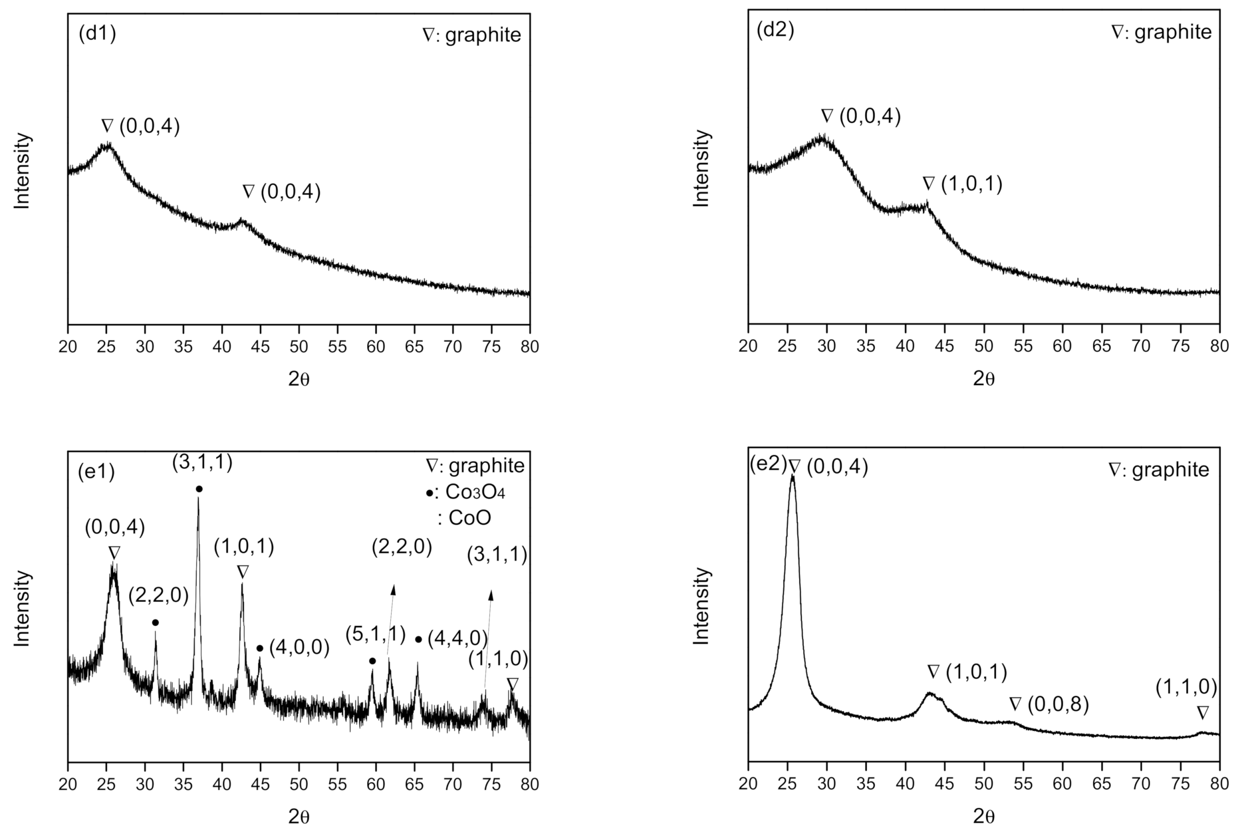
3.3. XRD Characterization

The XRD results of the various carbon-supported cobalt catalysts are shown in Figure 5. In brief, the 26.4°, 42.7°, 53.2°, and 77.7° peaks of graphite attributed to (0,0,4), (1,0,1), (0,0,8), (1,1,0) crystallographic plane, respectively (PDF#26-1080). The peaks at 31.1°, 36.9°, 44.9°, 59.6°, and 65.4° correspond to the (2,2,0), (3,1,1), (4,0,0), (5,1,1), and (4,4,0) lattice planes of Co3O4, respectively (PDF#65-3103). Furthermore, the XRD peaks at 61.9°and 74.4° are assigned to the (2,2,0) and the (3,1,1) lattice planes of CoO, respectively (PDF#65-290) [17,18]. The XRD results, as shown in Figure 5(e1), indicate that only Co3O4 were detected in Co/CNT, Co/AC, and Co/CNF catalysts, while both CoO and Co3O4 were detected in Co/CNF sample. The small amount of CoO could be attributed to the partial reduction of Co3O4 in the preparation process of the Co/CNT sample [19]. Particularly, neither CoO nor Co3O4 was detected in Co/GO and Co/rGO composites, as given in Figure 5(c1,d1). As mentioned in our TEM result, the lattice spacing is 0.243 nm in Co (3 1 1) surface of Co3O4, which is consistent with the data by Roya et al. [20].

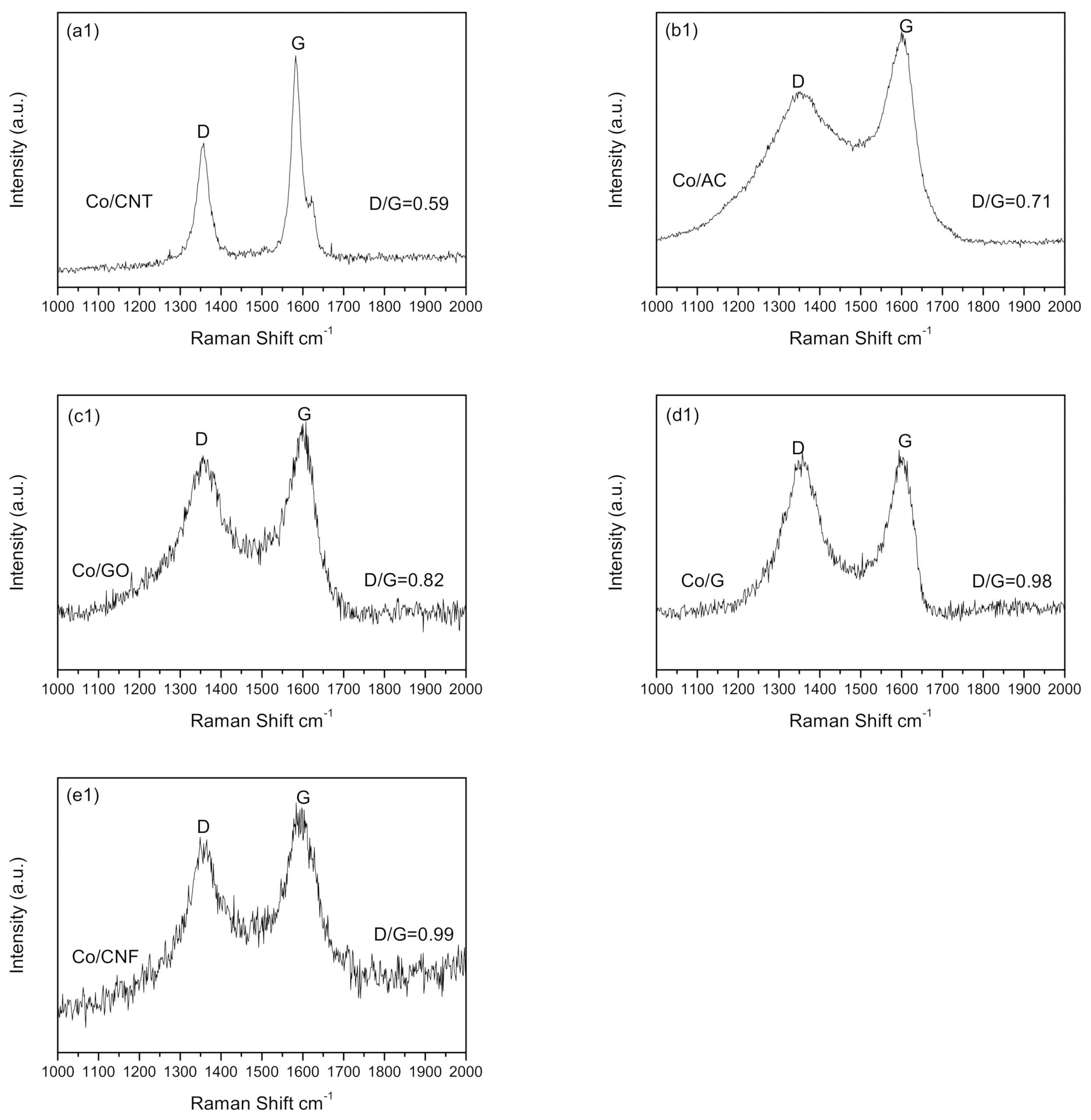
3.4. The Raman Spectroscopy of as Prepared Samples and Supports

The Raman spectroscopy characterization of as-prepared catalysts and composites is shown in Figure 6. Interestingly, two peaks in all the samples at 1348 and 1585 cm1 represent D and G peaks, respectively. G peak is related to the carbon atom vibration of sp2 hybrid orbital while D peak is related to the disarrangement of carbon atoms. The ratio of D to G band peak size is usually used to estimate the amount of graphitic carbon. For the well-ordered structure of these carbon materials, the D/G ratio is near zero [21,22,23,24]. Results from Figure 6 indicate that for Co/CNT, Co/AC, Co/GO, Co/rGO, and Co/CNF catalysts, D/G ratios are 0.59, 0.71, 0.82, 0.98, and 0.99, respectively. Increasing D/G ratios suggest an enhanced carbon disorderliness and growing numbers of defects on the surface of the materials. Similarly, more defect sites on the surface of the material could lead to the better dispersion of cobalt metal or the lesser aggregation of the cobalt clusters, which is beneficial to the dispersion of cobalt oxide. The size of the D band alone does not affect the value of the D/G ratio. In short, Raman spectra results suggest that the CNF is the best support among all carbon materials used to make cobalt catalysts and composites. Based on the Scherrer equation, the estimated Co3O4 crystallite size Co/CNT, Co/AC, and Co/CNF are 10.3, 7.5, and 12.4 nm, respectively.

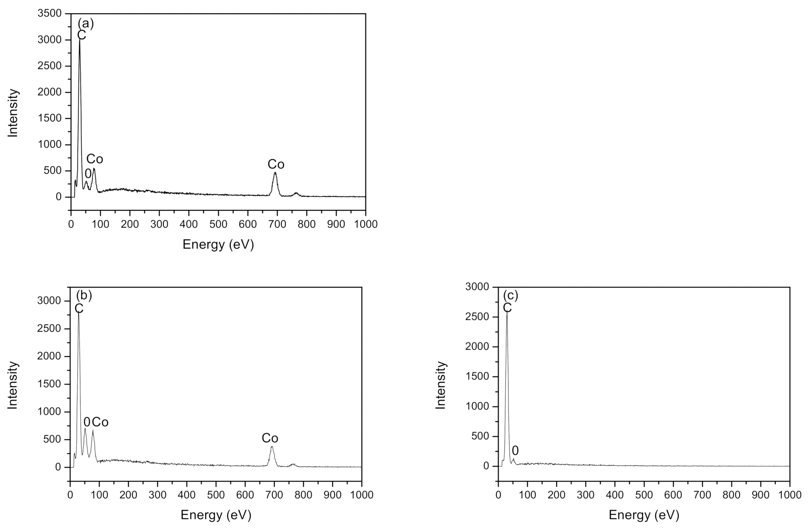
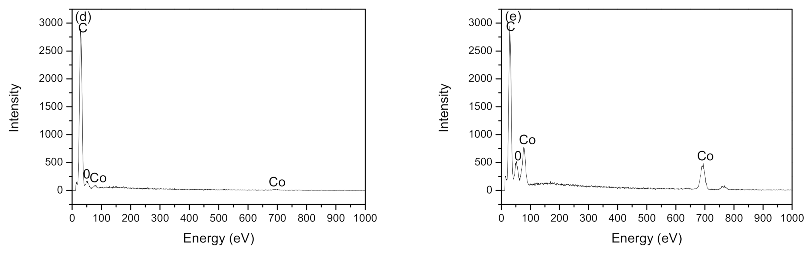
3.5. Cobalt Content Analysis from ICP

The ICP was employed to obtain the actual cobalt content of the prepared catalysts. As summarized in Table 1, the cobalt contents for Co/CNT, Co/AC, Co/GO, Co/rGO, and Co/CNF are 9.8%, 8.5%, 1.7%, 3.7%, and 9.9%, respectively. Although cobalt loading was prespecified, the loss of cobalt is inevitable in the actual preparation step, especially on the relatively inert carbon materials. Samples of Co/CNF, Co/AC, and Co/CNF can retain most of the cobalt in preparation, and 8.5–9.9% of cobalt loadings were obtained in all these three samples. However, the data in Table 1 show that the majority of the cobalt metal is lost in the preparation process, further confirming the results from SEM, EDX, and XRD.

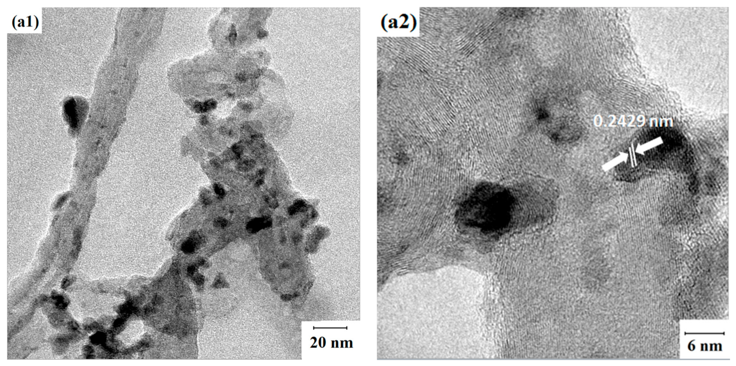
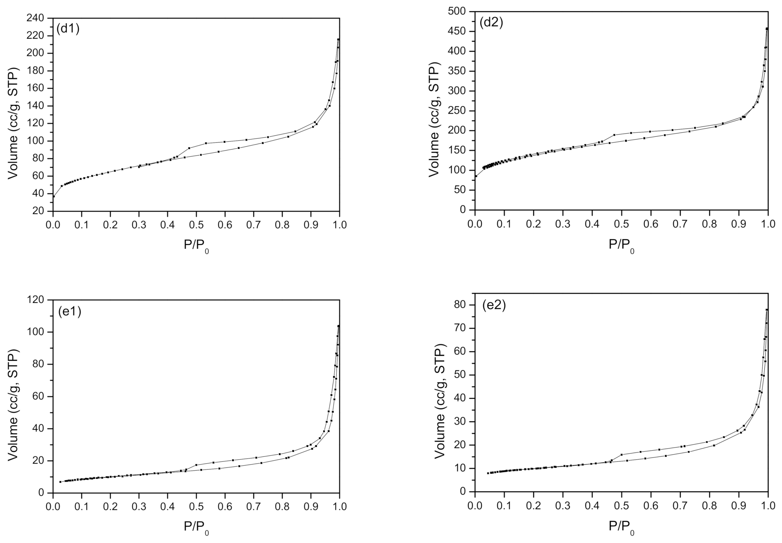
3.6. Microstructure Characterization of the Materials and the Catalysts

The nitrogen adsorption-desorption isotherms of as-prepared catalysts and supports are shown in Figure 7. It can be noted that all samples yielded a type IV isotherm. Due to the effect of capillary condensation, hysteresis loops appear after P/P0 = 0.45, which suggests that these carbon-based materials are featured with a mesoporous structure. Moreover, the hysteresis loops are type H3, indicating an unsaturated adsorption platform and an irregular pore structure.
The BET surface areas, pore volumes, and pore diameters of the carbon supports and cobalt catalysts are given in Table 2. The BET results indicate that the surface areas of the CNT, GO, and CNF supports and their corresponding catalysts are not markedly different. However, for the AC- and G-supported catalysts, loading of cobalt leads to a drastic decline in both surface area and pore volume. According to the SEM results, large Co3O4 particles on the supports might block the pores and reduce the surface areas and pore volume.

3.7. H2-TPR Measurements

The H2-TPR results of various carbon-supported Co catalysts are summarized in Figure 8. Our H2-TPR results are summarized in Figure 8. All H2-TPR curves exhibit three peaks, and the first at 250 °C may be due to the residual cobalt nitrate [25]. The peaks at 300–417 °C and at 480–600 °C are attributed to the conversion of Co3O4 to CoO, and then from CoO to Co, respectively [26,27]. The H2-TPR curve of Co/CNF is similar to that of Co/CNT and Co/AC, except that Co/AC shows a lower first step of reduction (Co3O4 to CoO) temperature than the other two, suggesting a similar cobalt–support interaction for Co/AC, Co/CNT, and Co/CNF. Interestingly, the reduction temperatures for the Co/rGO and Co/GO catalysts were found to be the lowest and highest values, respectively, among all samples, this suggested the weakest and strongest support-cobalt interaction for the two carbon supports and cobalt.

3.8. NH3-TPD Analysis of the As-prepared Catalysts and Supports

The NH3-TPD technique was used to measure the surface acidity of the as-prepared catalyst samples. As shown in Figure 9, three peaks at about 180, 423, and 673 °C correspond to the weak acid site, medium and strong acid sites, respectively [28,29,30,31]. Previously reported work by Wang et al. [32] suggested that the strong acid sites can improve the cobalt metal dispersion, leading to the formation of reduced cobalt oxide particle size. The acid site can promote the cobalt oxide reduction to metallic cobalt, which in turn, is beneficial to the catalyst performance. In brief, Figure 9 shows the strong acid site of all five types of catalysts increase in the order of Co/AC, Co/rGO, Co/CNT, Co/GO, and Co/CNF. The sample of Co/AC also shows the highest peak of weak acid, followed by Co/rGO and Co/CNT.

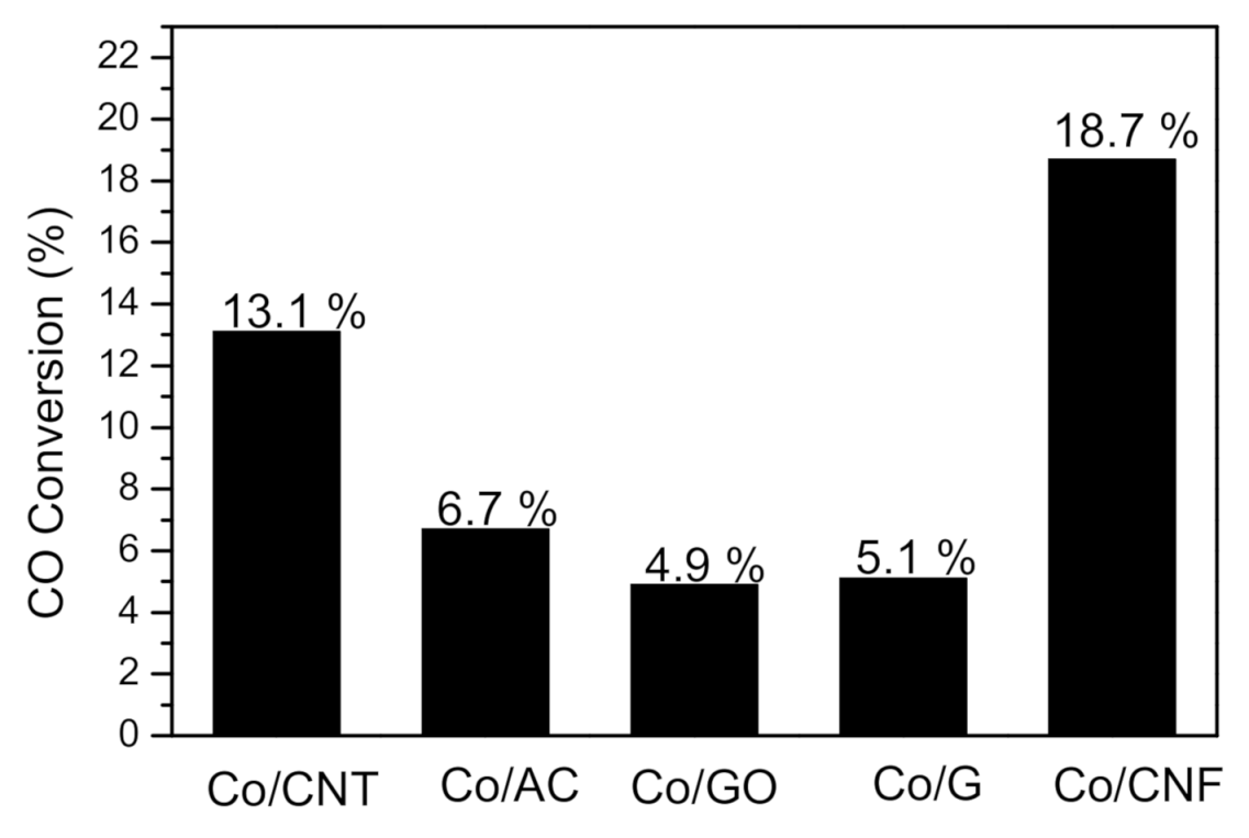
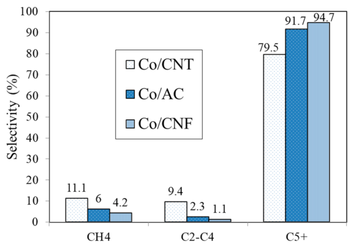
3.9. Fischer–Tropsch Synthesis Catalyst Performance

The Fischer–Tropsch synthesis reaction activity results are shown in Figure 10. The CO conversion of Co/CNT, Co/AC, Co/GO, Co/rGO, and Co/CNF are 13.1%, 6.7%, 4.9%, 5.1%, and 18.7%, respectively. The product selectivity results are given in Figure 11. Co/AC and Co/CNF yielded higher C5+ and lower CH4 selectivity than the Co/CNT sample, which also produced the highest selectivity to the gas products (C1-C4). Co/CNF not only exhibits the highest CO conversion but also shows the lowest gas product selectivity and highest C5+ selectivity. The higher CH4 selectivity over the Co/CNT can be partially attributed to the residual nickel from CNT preparation process.
For comparison, catalytic activities of all the five as-prepared catalysts are shown in Figure 12. The catalytic activity of Co/CNT, Co/AC, CO/GO, Co/rGO, and Co/CNF are 64.2, 35.4, 23.7, 13.5, and 92.3 μmolCO·g(Co)−1 s−1, respectively. In short, the specific activity of the catalyst samples can be ordered as: Co/CNF > Co/CNT > Co/AC > Co/GO/Co/rGO.

4. Conclusions

The various carbon materials including CNT, AC, GO, rGO, and CNF, and the cobalt catalysts supported on these carbon materials were characterized by DTA, nitrogen physisorption, XRD, Raman spectroscopy, H2-TPR, NH3-TPD, ICP, SEM, and TEM. Based on our results, it is concluded that Co3O4 particles can disperse uniformly on the supports of carbon nanotube, activated carbon, and carbon nanofiber, but not on reduced graphene oxide. Interestingly, these three types of carbon materials exhibit superior dispersion ability compared with reduced graphene oxide. TEM results indicate that cobalt metal can uniformly disperse on the surface of all the carbon materials except unpretreated reduced graphene oxide catalyst, thus properly pretreating the carbon material could be an effective way to modify the microstructures in the supports and improve the catalytic performance of the catalysts. Impregnation of cobalt can drastically affect the surface area and pore volume of AC and reduce graphene oxide catalysts. H2-TPR results confirm that the metal-support interaction is in the order of Co/GO, Co/CNT, Co/AC, Co/CNF, and Co/rGO, respectively. Among all as-prepared catalysts, the carbon nanofiber-supported cobalt catalyst showed the best dispersion, the highest CO conversion, and the lowest gas product, but the highest selectivity to heavy hydrocarbons (C5+). In conclusion, this may attribute to the intrinsic property of CNF material that can affect the catalytic performance. Considering varied FTS reaction performance over the five cobalt/carbon catalysts studied, it is concluded that the carbon materials have a significant influence on the catalyst structure and FTS reaction performance. This study is important to expand the application of carbon materials in the FTS field.

Author Contributions

S.L. and H.L. are mainly in charge of the laboratory work; Z.D. and Q.L. are in charge of the laboratory supervision; B.S. and A.W. helped data analysis and scientific discussion; B.L. and I.K. helped draft editing; M.L. is the overall supervisor and fund resourcing. All authors have read and agreed to the published version of the manuscript.

Funding

This research was funded by Special Research Fund from Beijing Institute of Petrochemical Technology grant number of 15031862004-1.

Institutional Review Board Statement

The study was not conducted involving humans or animals, thus, ethical review and approval were waived for this study.

Acknowledgments

Special funding from Beijing Institute of Petrochemical Technology and partial support from Beijing Key Laboratory of Clean Fuels and Efficient Catalytic Emission Reduction Technology are greatly acknowledged.

Conflicts of Interest

The authors declare no conflict of interest.

References

  1. Lin, L.; Zhou, W.; Gao, R.; Yao, S.; Zhang, X.; Xu, W.; Zheng, S.; Jiang, Z.; Yu, Q.; Li, Y.-W.; et al. Low-temperature hydrogen production from water and methanol using Pt/α-MoC catalysts. Nature 2017, 544, 80–83. [Google Scholar] [CrossRef]
  2. Zhai, P.; Xu, C.; Gao, R.; Liu, X.; Li, M.; Li, W.; Fu, X.; Jia, C.; Xie, J.; Zhao, M.; et al. Highly Tunable Selectivity for Syngas-Derived Alkenes over Zinc and Sodium-Modulated Fe5C2 Catalyst. Angew. Chem. Int. Ed. 2016, 55, 9902–9907. [Google Scholar] [CrossRef] [PubMed]
  3. Kapteijn, F.; de Deugd, R.M.; Moulijn, J.A. Fischer–Tropsch synthesis using monolithic catalysts. Catal. Today 2005, 105, 350–356. [Google Scholar] [CrossRef]
  4. Saib, A.M.; Moodley, D.J.; Ciobîcă, I.M.; Hauman, M.M.; Sigwebela, B.H.; Weststrate, C.J.; Niemantsverdriet, J.W.; van de Loosdrecht, J. Fundamental understanding of deactivation and regeneration of cobalt Fischer–Tropsch synthesis catalysts. Catal. Today 2010, 154, 271–282. [Google Scholar] [CrossRef]
  5. Iglesia, E. Design, synthesis, and use of cobalt-based Fischer-Tropsch synthesis catalysts. Appl. Catal. A Gen. 1997, 161, 59–78. [Google Scholar] [CrossRef]
  6. Van de Loosdrecht, J.; Balzhinimaev, B.; Dalmon, J.A.; Niemantsverdriet, J.W.; Tsybulya, S.V.; Saib, A.M.; van Berge, P.J.; Visagie, J.L. Cobalt Fischer-Tropsch synthesis: Deactivation by oxidation? Catal. Today 2007, 123, 293–302. [Google Scholar] [CrossRef]
  7. Dry, M.E. The Fischer–Tropsch process: 1950–2000. Catal. Today 2002, 71, 227–241. [Google Scholar] [CrossRef]
  8. Das, T.K.; Jacobs, G.; Patterson, P.M.; Conner, W.A.; Li, J.; Davis, H.B. Fischer–Tropsch synthesis: Characterization and catalytic properties of rhenium promoted cobalt alumina catalysts. Fuel 2003, 82, 805–815. [Google Scholar] [CrossRef]
  9. Tavasoli, A.; Trépanier, M.; Dalai, A.K.; Abatzoglou, N. Effects of confinement in carbon nanotubes on the activity, selectivity, and lifetime of Fischer− Tropsch Co/carbon nanotube catalysts. J. Chem. Eng. Data 2010, 55, 2757–2763. [Google Scholar] [CrossRef]
  10. Ma, W.P.; Ding, Y.J.; Lin, L.W. Fischer–Tropsch Synthesis over Activated-Carbon-Supported Cobalt Catalysts: Effect of Co Loading and Promoters on Catalyst Performance. Ind. Eng. Chem. Res. 2004, 43, 2391–2398. [Google Scholar] [CrossRef]
  11. Cheng, Y.; Lin, J.; Xu, K.; Wang, X.; Yao, X.; Pei, Y.; Yah, S.; Qiao, M.; Zong, B. Fischer–Tropsch synthesis to lower olefins over potassium-promoted reduced graphene oxide supported iron catalysts. ACS Catal. 2015, 6, 389–399. [Google Scholar] [CrossRef]
  12. Guo, X.N.; Jiao, Z.F.; Jin, G.Q.; Guo, X.-Y. Photocatalytic Fischer–Tropsch Synthesis on graphene-Supported Worm-Like Ruthenium Nanostructures. ACS Catal. 2015, 5, 3836–3840. [Google Scholar] [CrossRef]
  13. Bezemer, G.L.; Bitter, J.H.; Kuipers, H.P.C.E.; Oosterbeek, H.; Holewijn, J.E.; Xu, X.; Kapteijn, F.; van Dillen, A.J.; de Jong, K.P. Cobalt particle size effects in the Fischer− Tropsch reaction studied with carbon nanofiber supported catalysts. J. Am. Chem. Soc. 2006, 128, 3956–3964. [Google Scholar] [CrossRef] [PubMed] [Green Version]
  14. Bán, M.; Bombicz, P.; Madarász, J. Thermal stability and structure of a new co-crystal of theophylline formed with phthalic acid. J. Therm. Anal. Calorim. 2009, 95, 895–901. [Google Scholar] [CrossRef]
  15. Trépanier, M.; Tavasoli, A.; Dalai, A.K.; Abatzoglou, N. Fischer–Tropsch synthesis over carbon nanotubes supported cobalt catalysts in a fixed bed reactor: Influence of acid treatment. Fuel Process. Technol. 2009, 90, 367–374. [Google Scholar] [CrossRef]
  16. Madarász, J.; Pokol, G. Comparative evolved gas analyses on thermal degradation of thiourea by coupled TG-FTIR and TG/DTA-MS instruments. J. Therm. Anal. Calorim. 2007, 88, 329–336. [Google Scholar] [CrossRef]
  17. Chernyak, S.A.; Selyaev, G.E.; Suslova, E.V.; Egorov, A.V.; Maslakov, K.I.; Kharlanov, A.N.; Savilov, S.V.; Lunin, V.V. Effect of cobalt weight content on the structure and catalytic properties of Co/CNT catalysts in the Fischer-Tropsch synthesis. Kinet. Catal. 2016, 57, 640–646. [Google Scholar] [CrossRef]
  18. Trépanier, M.; Tavasoli, A.; Dalai, A.K.; Abatzoglou, N. Co, Ru and K loadings effects on the activity and selectivity of carbon nanotubes supported cobalt catalyst in Fischer–Tropsch synthesis. Appl. Catal. A Gen. 2009, 353, 193–202. [Google Scholar] [CrossRef]
  19. Bahaa, M.A.; Khalid, A.A. Green synthesis of 3D hierarchical nanostructured Co3O4/carbon catalysts for the application in sodium borohydride. J. Alloys Compd. 2019, 798, 820–831. [Google Scholar]
  20. Dehghan, R.; Hansen, T.W.; Wagner, J.B.; Holmen, A.; Rytter, E.; Borg, Ø.; Walmsley, J.C. In-Situ Reduction of Promoted Cobalt Oxide Supported on Alumina by Environmental Transmission Electron Microscopy. Catal. Lett. 2011, 141, 754–761. [Google Scholar] [CrossRef] [Green Version]
  21. Guo, S.; Dong, S.; Wang, E. Three-dimensional Pt-on-Pd bimetallic nanodendrites supported on graphene nanosheet: Facile synthesis and used as an advanced nanoelectrocatalyst for methanol oxidation. ACS Nano 2009, 4, 547–555. [Google Scholar] [CrossRef] [PubMed]
  22. Zhao, H.; Zhu, Q.; Gao, Y.; Zhai, P.; Ma, D. Iron oxide nanoparticles supported on pyrolytic reduced graphene oxide as model catalysts for Fischer-Tropsch synthesis. Appl. Catal. A Gen. 2013, 456, 233–239. [Google Scholar] [CrossRef]
  23. Karimi, S.; Tavasoli, A.; Mortazavi, Y.; Karimi, A. Enhancement of cobalt catalyst stability in Fischer–Tropsch synthesis using graphene nanosheets as catalyst support. Chem. Eng. Res. Des. 2015, 104, 713–722. [Google Scholar] [CrossRef]
  24. Zaman, M.; Khodadi, A.; Mortazavi, Y. Fischer–Tropsch synthesis over cobalt dispersed on carbon nanotubes-based supports and activated carbon. Fuel Process. Technol. 2009, 90, 1214–1219. [Google Scholar] [CrossRef]
  25. Chu, W.; Xu, J.; Hong, J.; Lin, T.; Khodakov, A. Design of efficient Fischer Tropsch cobalt catalysts via plasma enhancement: Reducibility and performance (Review). Catal. Today 2015, 256, 41–48. [Google Scholar] [CrossRef]
  26. Pour, A.N.; Karimi, J.; Taghipoor, S.; Gholizadeh, M.; Hashemian, M. Fischer–Tropsch synthesis over CNT-supported cobalt catalyst: Effect of magnetic field. J. Iran. Chem. Soc. 2017, 14, 1477–1488. [Google Scholar] [CrossRef]
  27. Chen, W.; Fan, Z.; Pan, X.; Bao, X. Effect of confinement in carbon nanotubes on the activity of Fischer− Tropsch iron catalyst. J. Am. Chem. Soc. 2008, 130, 9414–9419. [Google Scholar] [CrossRef]
  28. Bessell, S. Support effects in cobalt-based Fischer-Tropsch catalysis. Appl. Catal. A Gen. 1993, 96, 253–268. [Google Scholar] [CrossRef]
  29. Zhang, J.; Chen, J.; Ren, J.; Sun, Y. Chemical treatment of γ-Al2O3 and its influence on the properties of Co-based catalysts for Fischer–Tropsch synthesis. Appl. Catal. A Gen. 2003, 243, 121–133. [Google Scholar] [CrossRef]
  30. Su, H.; Zeng, S.; Dong, H.; Du, Y.; Zhang, Y.; Hu, R. Pillared montmorillonite supported cobalt catalysts for the Fischer–Tropsch reaction. Appl. Clay Sci. 2009, 46, 325–329. [Google Scholar] [CrossRef]
  31. Wang, S.; Yin, Q.; Guo, J.; Ru, B.; Zhu, L. Improved Fischer–Tropsch synthesis for gasoline over Ru, Ni promoted Co/HZSM-5 catalysts. Fuel 2013, 108, 597–603. [Google Scholar] [CrossRef]
  32. Wang, Y.; Jiang, Y.; Huang, J.; Wang, H.; Li, Z.; Wu, J. Effect of preparation methods on hierarchical zeolites for cobalt-based Fischer–Tropsch synthesis. RSC Adv. 2016, 6, 107498–107506. [Google Scholar] [CrossRef]
Figure 1. DTA patterns of (b1): Co/AC, (b2): AC.
Reactions 02 00005 g001
Figure 2. SEM images of (a1): Co/CNT, (a2): CNT, (b1): Co/AC, (b2): AC, (c1): Co/GO, (c2): GO, (d1): Co/rGO, (d2): rGO, (e1): Co/CNF, (e2): CNF.
Reactions 02 00005 g002aReactions 02 00005 g002b
Figure 3. EDX results of (a): Co/CNT, (b): Co/AC, (c): Co/GO, (d): Co/rGO, (e): Co/CNF.
Reactions 02 00005 g003aReactions 02 00005 g003b
Figure 4. TEM images results (a1): Co/CNT, (a2): CNT, (b1): Co/AC, (b2): AC, (c1): Co/CNF, (c2): CNF, (d1): Co/rGO, (d2): rGO.
Reactions 02 00005 g004aReactions 02 00005 g004b
Figure 5. XRD results of sample. (a1): Co/CNT, (b1): Co/AC, (c1): Co/GO, (d1): Co/rGO, (e1): Co/CNF, (a2): CNT, (b2): AC, (c2): GO, (d2): rGO, (e2): CNF.
Reactions 02 00005 g005aReactions 02 00005 g005b
Figure 6. Raman spectroscopy results of different carbon-supported cobalt catalysts. (a1): Co/CNT, (b1): Co/AC, (c1): Co/GO, (d1): Co/rGO, (e1): Co/CNF.
Reactions 02 00005 g006
Figure 7. Nitrogen adsorption-desorption isotherm of (a1): Co/CNT, (a2): CNT, (b1): Co/AC, (b2): AC, (c1): Co/GO, (c2): GO, (d1): Co/rGO, (d2): rGO, (e1): Co/CNF, (e2): CNF.
Reactions 02 00005 g007aReactions 02 00005 g007b
Figure 8. H2-TPR profiles of (a1): Co/CNT, (b1): Co/AC, (c1): Co/GO, (d1): Co/rGO, (e1): Co/CNF.
Reactions 02 00005 g008
Figure 9. NH3-TPD profiles of different carbon-supported cobalt catalysts.
Reactions 02 00005 g009
Figure 10. CO conversion of different catalysts.
Reactions 02 00005 g010
Figure 11. Product selectivity of different catalysts.
Reactions 02 00005 g011
Figure 12. Catalytic activities of different catalysts.
Reactions 02 00005 g012
Table 1. Inductively coupled plasma (ICP) results of as-prepared catalysts.
NotiationContent (Co, wt.%)
Co/CNT9.8
Co/AC8.5
Co/GO1.7
Co/rGO3.7
Co/CNF9.9
Table 2. Surface Area, Pore Volume, and Pore Diameter.
NotationSurface Area (m2/g)Pore Volume (m3/g)Pore Diameter (nm)
CNT1400.37010.6
AC15591.193.06
GO1840.56412.3
rGO4870.5644.63
CNF34.60.086610.0
Co/CNT1410.2727.72
Co/AC5520.4002.90
Co/GO1760.53012.1
Co/rGO2240.2784.97
Co/CNF34.70.11913.7
Publisher’s Note: MDPI stays neutral with regard to jurisdictional claims in published maps and institutional affiliations.

