A Cryptography-Powered Infrastructure to Ensure the Integrity of Robot Workflows


1
JOANNEUM RESEARCH-Institute for Robotics and Mechatronics, 9020 Klagenfurt, Austria
2
Alpen-Adria-Universität Klagenfurt-Software Engineering Research Group, University of Klagenfurt, 9020 Klagenfurt, Austria
3
Alpen-Adria-Universität Klagenfurt-System Security Research Group, University of Klagenfurt, 9020 Klagenfurt, Austria
*
Author to whom correspondence should be addressed.
J. Cybersecur. Priv. 2021, 1(1), 93-118; https://0-doi-org.brum.beds.ac.uk/10.3390/jcp1010006
Submission received: 18 December 2020
/
Revised: 8 January 2021
/
Accepted: 12 January 2021
/
Published: 14 January 2021
(This article belongs to the Section Security Engineering & Applications)
Abstract
:With the growing popularity of robots, the development of robot applications is subject to an ever increasing number of additional requirements from e.g., safety, legal and ethical sides. The certification of an application for compliance to such requirements is an essential step in the development of a robot program. However, at this point in time it must be ensured that the integrity of this program is preserved meaning that no intentional or unintentional modifications happen to the program until the robot executes it. Based on the abstraction of robot programs as workflows we present in this work a cryptography-powered distributed infrastructure for the preservation of robot workflows. A client composes a robot program and once it is accepted a separate entity provides a digital signature for the workflow and its parameters which can be verified by the robot before executing it. We demonstrate a real-world implementation of this infrastructure using a mobile manipulator and its software stack. We also provide an outlook on the integration of this work into our larger undertaking to provide a distributed ledger-based compliant robot application development environment.
1. Introduction
Robots have found more and broader fields of applications in recent years. As this trend is expected to increase in the coming years, more and more requirements for the widespread use of robots have emerged as well. While future robots will gain in autonomy, for the foreseeable future, robots will still be pre-programmed to fulfill a limited albeit arbitrarily complex set of tasks. No matter where a robot is used or how it was programmed, it is important that it actually executes the program that its developer has implemented. This is a key issue, especially since robots have strong safety implications in most of their fields of applications. However, also in general, we expect our technical systems to behave the way they were intended to and not be intentionally or unintentionally modified by unauthorized entities [1]. This expectation raises the requirement of program integrity which must be ensured from the finalization of a robot program until the end of its execution on the machine itself. Furthermore, legal or safety requirements must be considered. While there are established mechanisms to perform verification and validation of applications, there are currently hardly any mechanisms to protect an accepted application before its execution. This integrity however is key to make sure that the robot behaves in a way compliant to the specified requirements. Also the most relevant security standard in this area, IEC62443 defines in its part 4-2 the component requirement CR 3.4 that requires a component to provide methods to ensure software and information integrity [2].
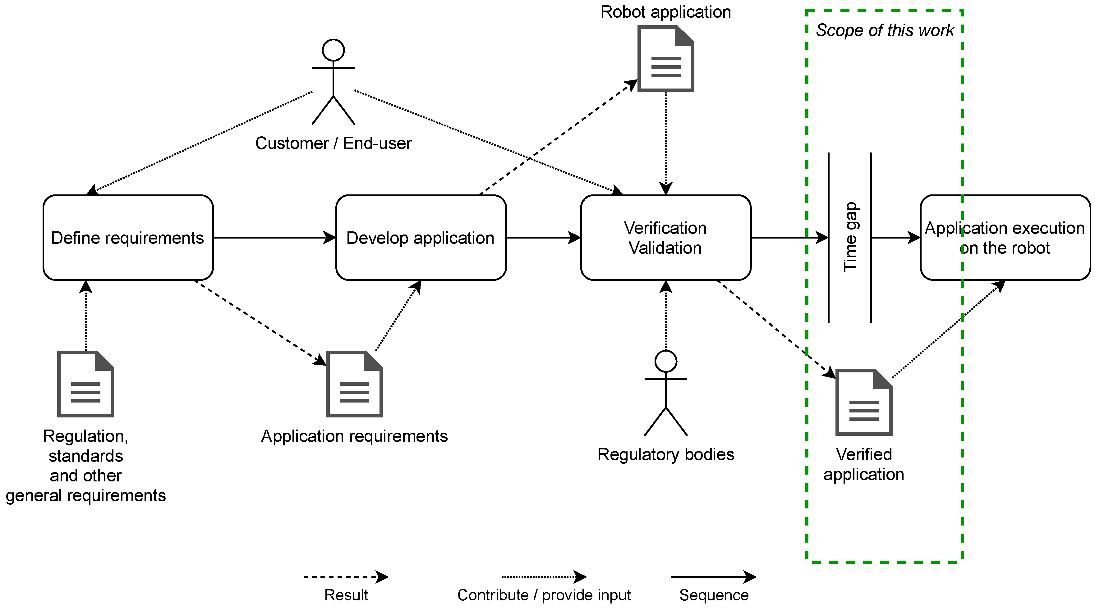
We assume a (simplified) process of how a robot application is developed as shown in Figure 1 (leaving out elements that are out of scope here such as iterations in the development or adaptations after deployment). The general requirements of the application are dictated by the end-user and are enhanced with regulatory requirements, standards and other inputs such as societal requirements or ethical considerations. From those requirements, a robot application is developed which is then verified and validated (V&V) by the end-user as well as potential regulatory bodies (e.g., in safety certification). In general, such a process should be accompanied by measures to track each step of the process to ensure compliance, traceability, and accountability. While today this is typically covered by conventional means such as measures from the ISO-9000 family, we will also present an outlook of how this can be integrated into the development process itself in Section 5. As part of this larger endeavour, we focus this work on preserving the integrity of the robot program after it has been developed and accepted. The basic idea is to seal the program after it has been accepted and prevent further intentional or unintentional modifications. This step is primarily assumed to happen offline i.e., temporally decoupled from the execution. As described below, there may be an arbitrarily long time gap between the acceptance and the execution. Thus, our approach ensures the integrity during this time gap. An authorized entity such as the program developer or manager shall be responsible to trigger the integrity preservation mechanism as described in the following sections but in general, this can be determined according to regulations or processes. However, in case automated program generation methods such as planners are used, also on-the-fly use of our approach is possible.
There are various ways of programming robots ranging from text-based to visual programming methods [3]. However, from an abstract point of view, we typically look at a pre-defined program in a certain form that has a central point of execution (we will discuss systems where this is different such as ROS later in this manuscript). Independent of the method of programming the robot, at some point the application is deemed finished and verification and validation checks for the compliance to regulations and requirements are done at this point. At some time after the V&V step, the application is executed. Preserving the integrity of the verified application is hardly addressed up to now but it must also be ensured that the application as designed by a developer is actually executed by the robot in an unmodified manner i.e., the application integrity is ensured from end of development until end of execution. As an example, a safety certification of a robot application is also bound to the unvaried program running on the robot. Sealing an application at some point in time is not a function typically provided by a robot. Concerns for the integrity of the application come from accidental or intentional modifications on the shop floor but also from a security-side. As discussed in the next sections, severe security problems exist in modern robots leading to potentials for program manipulation. Also, it should not be possible for anyone close to a robot to modify its programming as it is currently the case with most robotic systems.
We consider robot programs that have a central execution entity in this work. As discussed later-on, approaches that require distributed emergent behaviour such as ROS are more difficult—but not impossible—to secure. In general industrial use, the central execution entity approach is more common. Our approach considers externally controlled robots but—as sketched later—can easily be simplified for robots where programs are stored on the controller. We will further view robot applications as workflows that consist of individual actions (workflow steps) that instruct the robot to perform a certain task. The totality of a workflow then achieves a desired goal of the robot application. As an example, a pick-and-place application can be modeled as a workflow consisting of one or more move steps, a grip action, further movements and a release action. This generalization allows abstracting robot programming from vendor-specific approaches. Workflows are a more general way of looking at robot programs making it possible to transfer our approach to various robot environments. Note, that also the programming of autonomous robots and flexible systems can be abstracted this way since intelligent building blocks of a workflow (such as SLAM navigation or object detection) can be encapsulated in workflows or workflow steps. Based on this workflow abstraction, we want to look at integrity preservation of verified workflows.
In this work, we present an approach to ensuring the integrity of robot workflows using cryptographic means. The concept is presented separately from its implementation because it is generally applicable to robot applications. We use a cryptographic infrastructure where an authorized entity signs a given certified workflow and its parameters. The robot will verify the cryptographic signature before executing the program. We demonstrate the efficacy of our approach in a real application using a mobile manipulator where we implemented a verification component on top of our workflow engine. The results show that the added integrity checks do not cause significant overheads which would prevent a robot in fulfilling its task.
In the remainder of this publication we present relevant related work in Section 2, elaborate the requirements for workflow verification and introduce our concept for verifiable workflows in Section 3, present an evaluation in Section 4 and discuss the bigger picture of accountable robot application development in Section 5.
2. Related Work
In this section, we look closer at the three topics of programming, cybersecurity, and accountability of robots since they are the most relevant in our case. The protection of program integrity itself in classical software systems was recently extensively surveyed in this work [4].
2.1. Robot Programming
Traditionally, a robot application is pre-programmed on the robot itself where either configuration or teach-in methods [5] are used to find the optimal sequence and parametrization of robot movements or classical text-based offline programming is done. While this is still the most common way of programming a robot, advanced methods are gaining popularity. From application development in simulation and using digital twins to model-based and visual programming, many approaches were presented and also start gaining popularity in industry [6,7,8]. Please note that we are not directly considering robot applications that are built as distributed systems such as ROS where the behaviour of the application emerges from the behaviour of individual nodes but descriptive approaches that have a single point of execution. In general, we foresee our approach to be later-on also applicable to ROS but sealing such an application is significantly more difficult. Our group has however already presented an approach in previous work that at least secures such an application by denying access to unauthorized nodes at application level [9]. Also this approach makes use of an external service to secure the robot application. Furthermore, we discuss the integration of ROS in our concept in Section 4. Also for ROS, approaches to visual programming exist such as that recently presented for ROS2 (https://www.eprosima.com/index.php/company-all/news/175-eprosima-presents-visual-ros) or in [10]. Since it is rather easy to manipulate ROS itself [11], still protection against manipulation of the underlying ROS application will be necessary.
2.2. Robot Cybersecurity
One major important reason to ensure integrity of robot applications, is the potential malicious manipulation of robot systems. Konstantinou et al. have surveyed the potential security risks and challenges for cyber-physical systems in general [12]. Also in this area, the protection of software was identified as a key requirement. As an example, Mo et al. have pointed out and formalized integrity attacks on cyber-physical systems [1]. It has been pointed out that robots tend to be not adequately secured as studies on ROS [11,13] or also robots in general [14,15,16,17,18,19] have demonstrated. Very recently, TrendMicro has pointed out the malicious potential of modified robot programs [20,21]. Consequences can range from stolen data via injected movements up to full-fledged malware attacks. A tool and an evaluation for the detection of suspicious code patterns have been presented. Such an approach could well be combined with our approach. Several strategies for mitigation of security risks in robotics have been presented [22,23,24,25,26,27]. Protecting the integrity of the robot’s software and programming must be an essential part of a holistic security concept.
2.3. Accountability in Robotics
As the complexity of robots increases along with the breadth of use, further requirements regarding the accountability and traceability of robots emerge. As an example for such requirements, we want to hint at the HLEG guidelines for ethical AI of the European Commission [28] that can to a large part also be applied to modern robotics. There, properties like accountability and human oversight are demanded. Also in robotics, those are important factors.
The authors of [29] tried to find a modern definition of Asimov’s three laws called the three laws of responsible robotics. Law 1 reads “A human may not deploy a robot without the human–robot work system meeting the highest legal and professional standards of safety and ethics.” thus defining in some way the background to our work. Law 2 is re-defined as “A robot must respond to humans as appropriate for their roles” thus effectively defining some of the requirements fulfilled by this work that only authorized entities may give instructions to a robot (in form of programming in our case).
In [30], Heyer describes scenarios of robot use in critical areas. He argues that accountability is a key point whenever the operator needs to rely on the robot’s correct task execution.
Kacianka and Pretschner have presented a formalization of accountability for cyber-physical systems [31]. Such a formalization allows for comparison of different accountability approaches and makes it possible to define the exact accountability properties for a certain system. Together with what the authors have presented in [32], this enables the applied consideration of accountability for systems that interact with the environment.
Technical systems that support accountability by recording data are often referred to as black box systems. From the original concept developed for airplanes [33], many offsprings have been developed in different fields. For robotics, our group has presented a cryptographically secured black box system that can be a software component or a dedicated device [34]. White et al. have presented a blockchain-based solution for ROS2 [35].
For mobile service robots, Guerrero et al. have presented a framework and a black box component for [36]. The group has also presented an approach on how to integrate accountability logging into ROS [37] and has demonstrated how a graphical environment can support the processing of accountability data [38].
All the work mentioned here fuels our effort to protect robot programs in distributed environments and make the development of robot applications compliant and eventually trustworthy.
3. Compliance Architecture
In this section, we present the requirements and the general concept of preserving the integrity of workflows in a compliant and accountable development of robotic applications. We assume a generalized execution entity (e.g., the environment running on the robot controller or a workflow system in our case presented in Section 4). After presenting the requirements defined for our work, we illustrate the extended architecture including the necessary compliance infrastructure. Finally we describe the information flow including the transported data structures as well as the underlying cryptographic concept in more detail.
3.1. Accountability Requirements
In this section we derive requirements for accountable development of robotic applications.
- Workflow integrity:
- The integrity of the workflows to be executed is essential in our concept. It must be made sure that the workflow as designed by the application developer and signed off by a responsible entity is actually executed without reductions, additions or modifications. This includes the flow itself meaning the sequences and branches of actions as well as the parameters of each action. Since e.g., the speed of the robot can dramatically impact the outcome of the robot’s action, the integrity of parameters is a crucial part of the workflows integrity.
- Authentication:
- All participants in the transaction from sealing an application to its execution must be authenticated in order to later be able to authorize them.
- Authorization:
- To make a robot only accessible by entities with the appropriate permissions, the access to the verification infrastructure must be protected by authorization measures.
- Traceability:
- We require every action taken and every event happening from the design of the workflow until the execution on the robot to be reconstructable in a timeline after the execution of the application (post-morten). Please note that not all elements required for full traceability are in the focus of this work. However, as an additonal step towards full trusted traceability, our group has already presented a secure data recorder (the robot black-box) in previous work [34].
- Non-repudiation:
- Traceability should be supported by non-repudiation meaning in our case that an entity cannot deny having taken a certain action. Specifically, we address that signing off and triggering the execution of a workflow can provably be assigned to a certain entity in the overall system. Non-repudiation can be achieved with authentication and traceability in the overall concept which we present in Section 5.
- Confidential communication:
- The communication between the components involved in our system must be kept confidential as not to give potential malicious agents attack surfaces to tamper with our system. This is required for the communication between all entities (client, robot and infrastructure).
- Low overhead:
- Despite the valuable addition of making workflow execution verifiable and traceable on robot systems, the added overhead of the implemented measures must not impact the robot in its execution. Many factors of a robot’s operation are time-critical and thus, added verification steps must not hinder those operations.
- Scalability:
- The infrastructure added for verifiable workflow execution must be scalable to support large workflows on the one hand and also a scalable fleet of robots on the other hand. The support for queues of workflows that describe more complex applications must be considered.
3.2. General Approach
Before we focus on our architecture, we clarify the meaning of compliant and accountable robotic application development in the context of our concept. For this, we suppose a client wants to execute a program composed of a sequence of workflows on our robotic system and present measures, which guarantee the fulfillment of the previously defined requirements:
- Workflow sequence signatures:
- Workflow sequences intended to be executed on the robot system have to be signed by a trusted third party that supports automation of this process i.e., a dedicated signing service. Additionally, the system must be able to verify the signature before the execution is initiated. If the verification fails, the process is aborted in a graceful way without compromising the overall state of the system. This measure not only ensures the integrity of the workflow sequences per se, moreover it allows preventing a client from executing workflow queues, that do not fulfill a set of predefined criteria. In this section, we focus on the first aspect and deal with the second in a later part of the paper.
- Public-Key-Cryptography:
- Fulfilling the requirement of authenticity in our context demands to guarantee that the workflow sequence was not signed by the client itself. A common way to achieve this behaviour is the implementation of a public key infrastructure where each entity is initialized with a public key certificate and a corresponding private key. Using the latter for signing and providing the certificate to other entities allows checking whether the signature originates from the right source or not. In our context, this means that the trusted third party signs the workflow sequence with its private key and the robot system can verify the signature by using the corresponding public-key. For simplicity we reduce our implementation to using only a private key for the signing process leaving the verification of the signature to the trusted party. We refer to this aspect in our discussion section also targeting the related non-repudiation requirement. Matters of key-management including generation, initial distribution, storage, update, use and destroying keys are out of the scope of this work and are assumed subject to standardized organizational regulations designed for this purpose.
3.3. Adding Workflow Verification to an Execution Entity
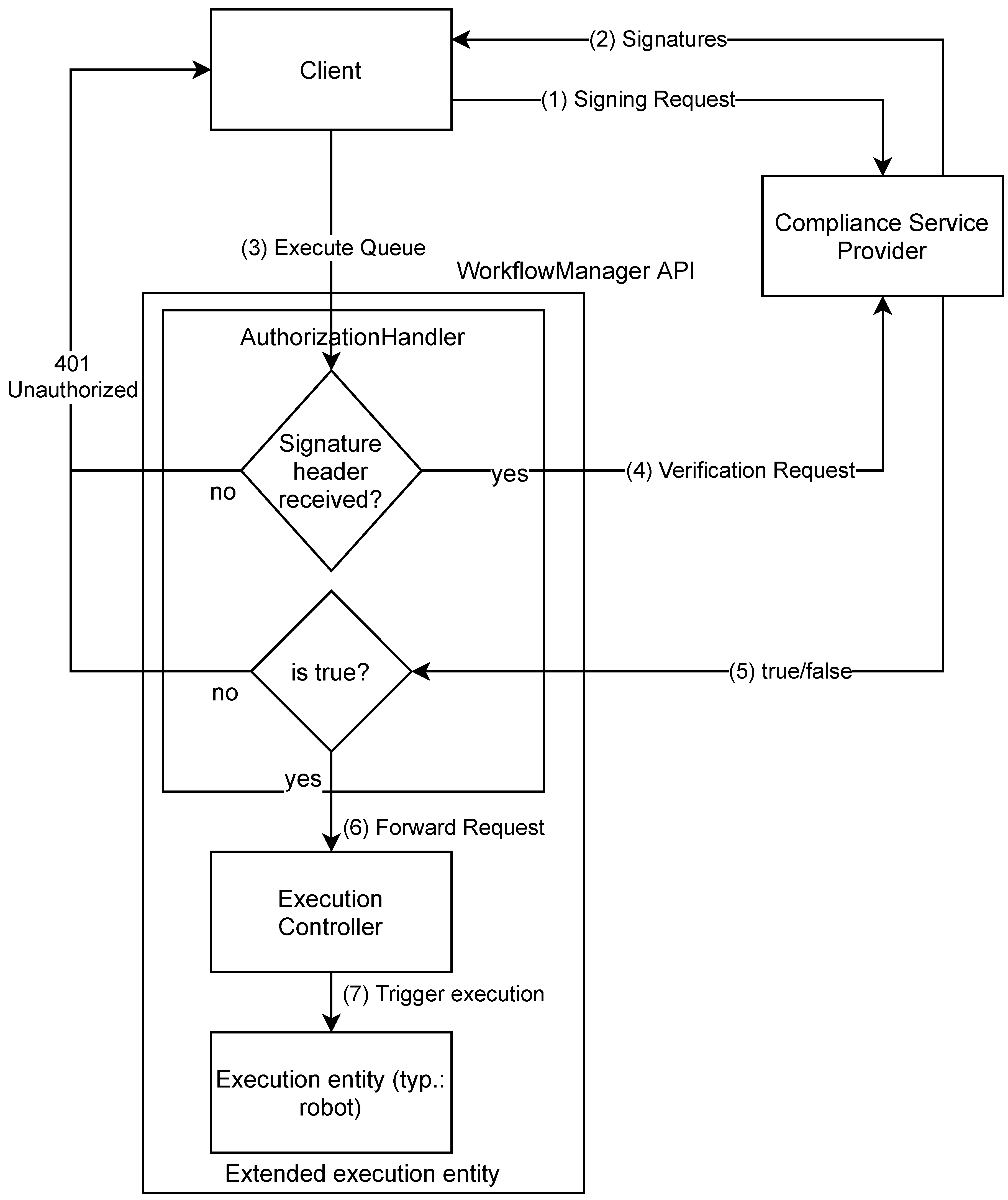
To add compliance capabilities to an execution entity, we foresee the architecture described in Figure 2. On top of the execution entity, we add an execution controller. Its purpose is to orchestrate the execution of signed workflow queues. The authorization handler is tasked with verifying that the client has sufficient rights to perform a certain action. The compliance service is an external, trusted service that digitally signs workflows upon request of the client. The authorization handler requests a signature verification from the service upon invocation of a workflow. A request of a client who is not authorized or whose signature is invalid will not be invoked. By using digital certificates, the communication between authorization handler and compliance service can be skipped.
3.3.1. Client
The client is modeled as an agent targeting the execution of workflow queues on our robotic system. This can be a human interacting via a user interface or the triggering of a pre-programmed workflow or also an autonomous agent such as an internal planning module or an external fleet management system. In both cases, the client needs to adhere to the compliance and accountability requirements, which may take different forms and details depending on the application context (so we leave the details open here). Considering this, we need an interface for retrieving signed workflow queues on the one hand and an interface for executing workflow queues on the robotic system on the other hand.
Robot programs to be executed by the execution entity can be stored local and triggered externally or the robot can be externally controlled. In case the program is already stored on the robot controller, the verification should be done before execution. In case of external control, the verification is performed on the fly as the workflows are transmitted. In general, we look at the latter case since it is the more complex one. However, transferring our approach to a local storage scenario is quite straightforward. We mention that it is necessary that the deployment of the program needs to also contain the signature step and that the signature must be stored alongside the program.
3.3.2. Execution Controller
The execution controller enables the execution of workflow queues on systems that do not support this out of the box. As an example, on a robot system where only a single program can be triggered, the execution controller will orchestrate the subsequent execution of multiple programs. This feature is required to enable the bulk signature of larger programs. Otherwise, it would be required to sign each workflow individually potentially requiring each robot movement to carry a specific signature. This would not only be tedious and cause additional overhead but also the overall integrity of the program could no longer be ensured meaning that single steps or workflows could be re-ordered without being noticed.
3.3.3. Compliance Service Provider (CSP)
The Compliance Service Provider runs services for signing workflow queues and verifying workflow queue signatures. To ensure the integrity of workflows, the CSP protects the types, order and parameters of workflows. In general, the implementation of the CSP is free to choose the specific cryptographic algorithms—as long as they are sufficiently secure—since the CSP is the only agent performing the cryptographic actions. We will mention the algorithms that we used in our implementation throughout the remaining document. However, depending on the application and implementation constraints, others may be selected. It is set up with the necessary key material for the signing and the verification process as well as a cryptographic hash function for hashing the workflow information. To use the CSP, a suitable representation for a workflow has to be chosen. In our case (see below), we use a JSON formatted representation. For other systems, this may vary.
The CSP needs to be secured in terms of access by providing authentication and authorization facilities. In the easiest case, also API tokens could be used. A sufficiently sophisticated mechanism can also be used to ensure that only authorized persons trigger the signature of a workflow. Typically, we assume this to be a responsible manager whenever a robot program has gone through verification and validation. By triggering the signing process, this person then takes responsibility for the correctness of the program.
3.4. Dynamic View and Information Flow
In the following subsection, we focus on the behaviour and information flow in our architecture. For that we assume that a client wants to execute a workflow queue on the execution entity and describe the resulting communication and the execution steps on each component.
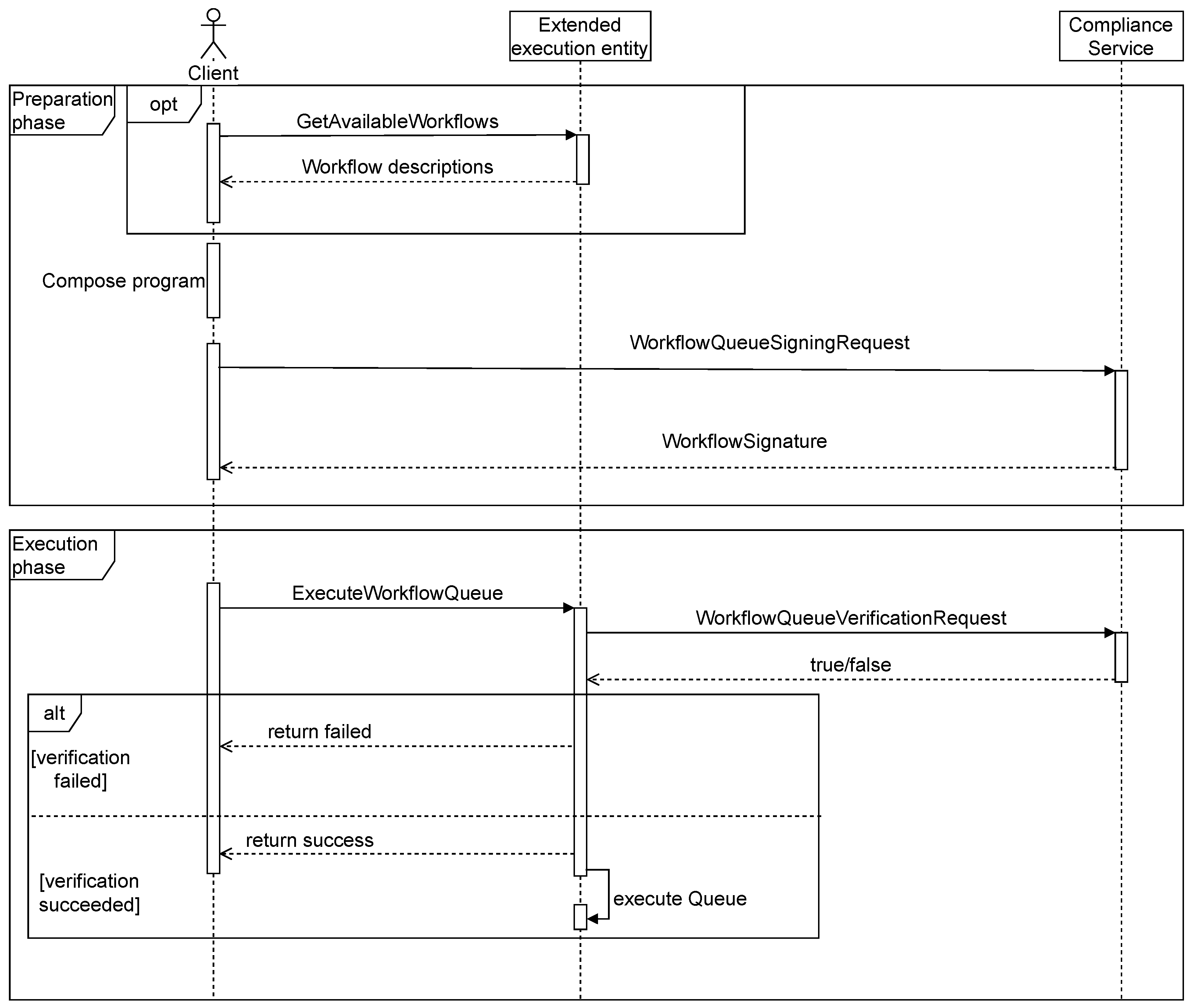
Figure 3 shows a sequence diagram which describes the information flow in our architecture. The communication can be split into two phases: (1) a preparation phase, where the client requests a signature for the workflow queue she intents to execute and (2) an execution phase where the workflow queue is sent to the workflow manager. Note, that as shown in Figure 1, the execution phase needs not be initiated immediately after the preparation phase, which means that there can be an arbitrary amount of time between them. Next, we describe the two phases in detail, the corresponding data structures as well as relation between them are depicted in Figure 4 below.
3.4.1. Preparation Phase
Prior to composing a program, the client needs to know which workflows the robot supports. This is either inherent knowledge or the client retrieves the available workflows directly from the execution entity. The response contains a list of workflow names including the corresponding workflow description. Having this information the client builds a WorkflowQueue object which consist of a list of workflow name/workflow parameter pairs. Executing a workflow queue with the execution entity requires a successful verification of the signature chain corresponding to this queue. Hence the client sends a WorkflowQueueSigningRequest to the CSP which is initialized with the CSP’s private key and a cryptographic hash function. The following steps describe the cryptographic mechanism used to sign the workflow queue.
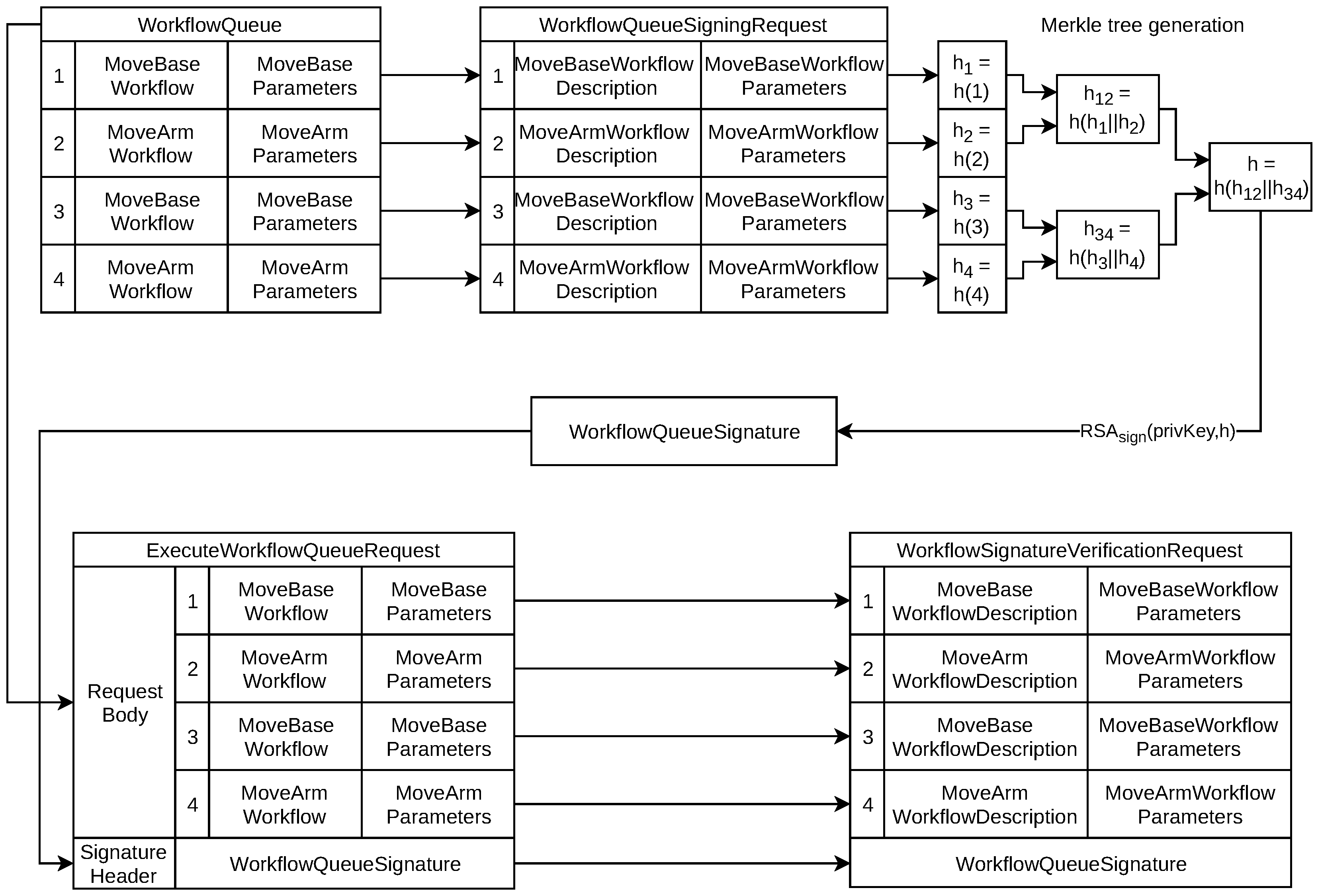
To protect the order of workflows, the CSP needs to use a specific data structure that enables the detection of workflow reordering within a queue. Multiple potential solutions can be chosen, we mention three alternatives here: Merkle trees, Verkle trees or the concatenation of all workflows. A Merkle tree [39] is a tree structure of hashes where a leaf node contains the hash of a certain data item (in our case, a single workflow) and where a non-leaf node contains a hash of its child nodes’ hashes. This allows for arbitrary interleaving of workflows where each workflow is integrity-checked using an individual hash and were the sequence of workflows is ensured by hashing the child nodes’ hashes. A Verkle tree [40] is a variation of the Merkle tree that uses vector commitments thus reducing the trees proof size. An alternative approach to ensuring the integrity of the overall queue could be to concatenate all workflows and sign their cumulative hash. However, in this case it would not be possible to find out which part of the queue has been modified. In addition, as we point out in our outlook, a Merkle or Verkle tree will enable the use of sanitizable signatures that will allow parts of the workflows to be modified by authorized actors even after signing. For the rest of this paper, we will assume that a Merkle tree is chosen.
As a superordinate data structure, we are using Merkle trees since the binary Merkle tree is more efficient in its construction than the corresponding Verkle tree as the construction is the most used operation in our concept. However, when we mention a Merkle tree in the remainder of the document, any other method of order integrity preservation can be substituted.
We leave it open which kind of hashing method is used by a specific implementation but urge to use modern, strong hashing like SHA2/3. Similar, also the signature algorithm should be state of the art such as RSA.
Based on this, the CSP performs the following two steps:
- Generate a Merkle tree from the workflow instances contained in the workflow queue. For that each workflow instance is hashed, by concatenating the workflow description and the parameter string and finally applying the hash function to it. These hashes are then paired up and a new hash is generated from each pair. This is repeated until the root of the tree has been generated.
- Sign the root of the Merkle tree with the private key and get the signature of the workflow queue as result. By signing only the root of the Merkle tree, the signing process is very efficient.
The resulting signature allows for the verification of the workflow queue in terms of containing the right workflows and having them in the right order. After finishing the signing process the CSP sends the signature back to client, who merges it with the initially created WorkflowQueue object to get an ExecuteWorkflowQueueRequest. The request body contains the WorkflowQueue object, whereas the signature is defined as a separate request header.
3.4.2. Execution Phase
In the execution phase the client calls the executeWorkflowQueue method of the extended execution entity. As soon as the request enters the execution pipeline, it is passed to the authorization handler where the verification of the signature takes place. For that, the handler fetches the workflow descriptions of the queue’s workflows from the execution entity and generates a WorkflowSignatureVerificationRequest also using the workflow parameters and the signature parsed from the signature header. The resulting request is sent to the CSP which then executes the following procedure in order to verify the workflow queue signature:
- Generate a Merkle tree from workflows contained in the verification request (see signing procedure).
- Verify the root of the resulting hash tree against the signature received from authorization handler. Return true in case of success, false otherwise.
This procedure ensures that each workflow instance in the queue and in addition also the order of workflows are verified. After the verification process has been finished, the CSP returns the result to the authorization handler. Again, the procedure above can be performed within the authorization handler itself in case a certificate-based public-key infrastructure is used.
In case of a negative response the API returns an error code immediately without further processing the ExecuteWorkflowQueueRequest object. If the signature has been verified successfully, the request is passed to the execution controller which parses the request body and initiates the workflow queue execution at the underlying execution entity instance.
4. Application and Evaluation in a Real Robot System
In this section, we demonstrate how to apply our approach in a real robot system. We chose a particularly complex system which combines two separate robot systems that can be jointly programmed with workflows. We first demonstrate how the concept is implemented on top of the robot’s software stack. Second, we evaluate it in a real use-case to investigate any additional overhead.
4.1. Application in an Industrial Robot System
We apply our verifiable workflow approach to a use-case using our mobile manipulator CHIMERA. The task for the robot is to pick up material at one position, transport it to another and place it into the designated area. The use case is realized as a sequence of non-interrelated workflows, which means that the parameters of each workflow do not depend on the outcome of any previously executed workflow.
4.1.1. The CHIMERA Robot
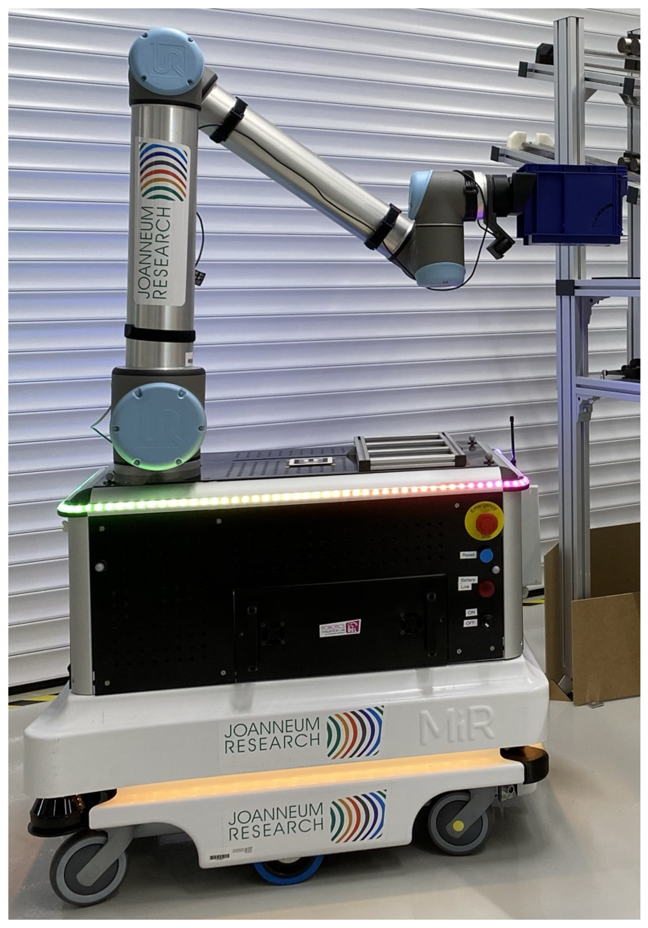
The robot used in our use-case is a mobile manipulator called CHIMERA (shown in Figure 5). CHIMERA is a mobile manipulator consisting of the mobile industrial platform MiR100 and the industrial robot arm UR10. It is intended for applications like intralogistics, machine tending or location-independent manipulation. Both robots are individual sub-systems that are integrated using dedicated computing hardware and combined in a shared software environment (see below). However, in hard- and software, we designed CHIMERA for the base and the arm to be exchangeable with other robots. To integrate the two robots both physically and logically we employ additional network hardware, an industrial PC as well as PLCs. Apart from that, a separate battery system ensures the endurance for complex industrial applications.
The software stack—as described below—runs on the industrial PC communicating with MiR and UR via the internal network. From the software perspective on application layer, CHIMERA provides workflows for moving the arm and for changing the robots location using the mobile base via the API. We are going to use these workflows in order to assemble a workflow queue for the upcoming evaluation part.
4.1.2. Use-Case Workflow
The workflow queue is depicted in Table 1, Figure 6 shows to exemplary steps as recorded in the final application. The material is stored in material holders which are provided on a rack. The rack has a known geometry and an Aruco tag [41] attached to it. By scanning the tag with its wrist cam, the robot can deduct the poses at which items can be picked up. This process compensates for the inherent position inaccuracy of the mobile base and provides extra flexibility in the placement of material. The robot first moves to a dedicated pickup location. There it scans the tag and picks up items. After placing them on its cargo bay, the robot drives to the placement location, again scans a tag to calculate the placement position and places material. From Table 1 it can also be seen that we combine various re-usable workflows into the final queue to achieve this goal.
Using our client implementation described in Section 4.2.2, we evaluate the execution of the workflow sequence. We first conduct a test without using our verification infrastructure and second test it with the workflow verification active to compare both scenarios. This gives an indication on the overhead introduced by our approach.
4.1.3. Integration into a Robotics Software Stack
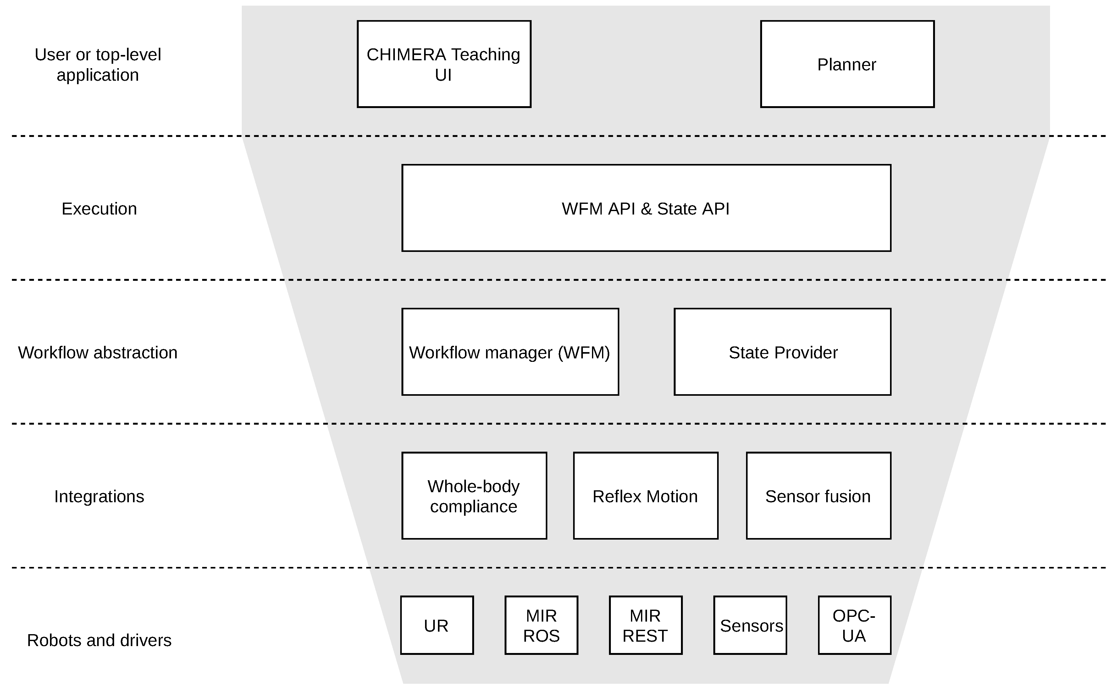
As basis of our use-case, we use our internal software stack further developed from what our group presented in [42]. It is a layered collection of re-usable components that can be applied to various robots and applications (see Figure 7). The bottom layer defines drivers for individual robots and other devices like sensors. In the case of CHIMERA, there are drivers for the UR arm and the MiR robot base (we can either choose a ROS-based driver or a driver that uses the MiR REST interface). Above that, the next layer defines various modules for integration of devices like one for whole-body compliance as presented in [43,44] or sensor fusion and advanced motion planning.
The workflow manager on the workflow abstraction layer orchestrates the execution of pre-defined sequences of actions. The state provider on the same layer collects information of the internal components and provides that to all other components. Both components are exposed to external entities by REST-based APIs on the Execution layer (the workflow manager API and the state API). The workflow manager API is a re-usable module that can be configured according to the capabilities of the underlying robot system. In the context of the CHIMERA robot, it allows for e.g., triggering movements of the mobile base or the robot arm (in joint and cartesian spaces) as well as support functions like the detection of AR tags using the wrist camera. The API provides asynchronous handling methods by returning an ID for each triggered workflow and the ability to query the status of such a workflow as it is being executed. Similarly, the state API adapts to the state data available from the robot system and exposes this data to the outside.
Above that, components like UIs or planners can be used to (i) instrument single robots and (ii) coordinate fleets of robots. Security-wise, the software stack is configured and deployed according to our recommendations published in [27]. The components below the execution layer are not accessible from outside the stack itself. Thus, the API provides a well defined access channel to the robot which is secured using encrypted communication via https as well as API tokens for authorization.
As we mentioned above, sealing ROS applications is more difficult. However, within our software stack, we are able to securely do so. We already presented an architecture for how to securely modularize robotic applications [27] including ROS modules. Our software stack adheres to this concept. We can also use ROS in our stack as individual modules e.g., on the driver level. Above we provide workflow abstractions of individual ROS actions, services and publications to make them accessible in the workflow manager. The abstraction in combination with security measures also enables securing ROS applications with our concept.
4.2. Adding Workflow Verification to the Robotics Software Stack
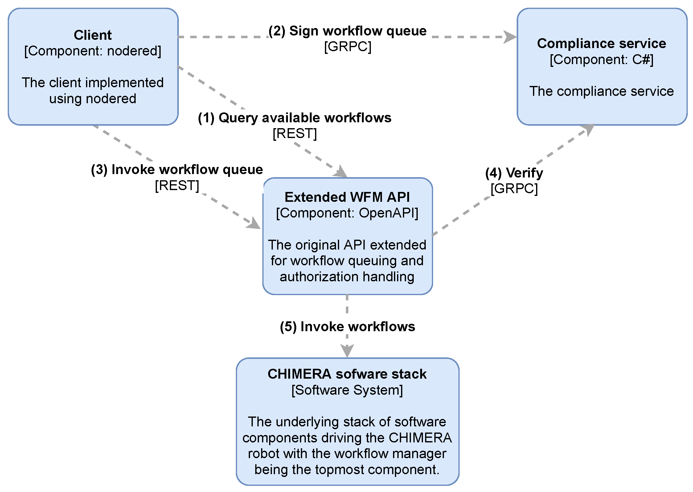
As described in Section 3 the workflow manager needs to verify the signature of the workflow queue sent by the client. For that the workflow manager uses the signature verification service of the Compliance Service Provider. In our realization of the architecture, the CSP provides a GRPC (https://grpc.io/) service. Accordingly, we initialize a GRPC client in the workflow manager’s authorization handler, which is then used to send a WorkflowQueueSignatureVerificationRequest to the verification service. In the following, we describe the architecture components in more detail. Figure 8 gives an overview of how we implemented the concept as a C4 model. The execution controller and authorization handler have been directly integrated into the workflowmanager API. Note, it would also be possible implement the execution controller and the authorization handler in a separate, external component and use the workflow manager API to execute individual workflows. In this case, we would use an API token to secure the access to the API.
The client is an implementation in Node-RED (see below) and the compliance service has been implemented as a separate component.
4.2.1. WorkflowManager API
The workflow manager API does not by itself provide facilities to execute workflow queues. The only comparable function so far is the ability to compose workflows from multiple individual steps (like arm and base movements) in arbitrary length. However, they have to be pre-programmed and can only be triggered via the API as a whole.
As we want execute and verify a queue of workflows on the workflow manager, we need to define and provide an ExecuteWorkflowQueue method in our WorkflowManager API. We add an AuthorizationHandler to the methods execution pipeline for fetching the workflow queue signature from the request and triggering the signature verification process.
The stock workflow manager API already contains a GetAvailableWorkflow method such that the capabilities of the underlying platform can be queried. This can be used in the program composition phase by the client as described in Section 3.
4.2.2. Client Implementation with Node-RED
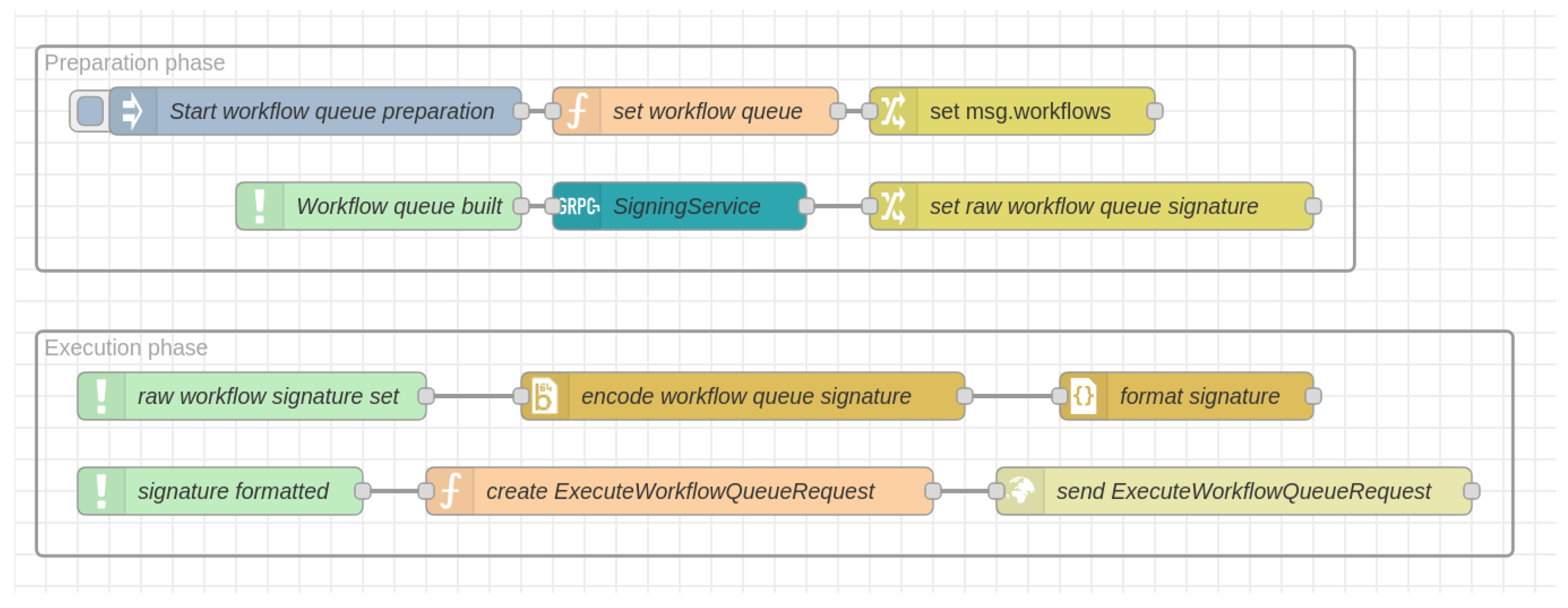
Our client implementation used for the evaluation is implemented within a graphical programming platform called Node-RED (https://nodered.org/), which is based on the javascript framework Node.js (https://nodejs.org/). Figure 9 shows the client implementation within the Node-RED programming interface. As in the description located in the previous chapter the information flow is grouped in a preparation phase and an execution phase.
Node-RED has an extensive library of components such that the invocation of the GRPC service and the REST service calls are easy to implement.
From the available workflows, we constructed the use-case within the Node-RED environment. We use a queue of base and arm movement workflows to achieve the desired behaviour. Once finished, we make use of the compliance service client shown in the upper box of Figure 9 to receive the workflow queue signature. Then, the lower box is used to send the queue to the extended workflow manager API. After assembling, the workflow queue needs to retrieve the workflow queue signature from the Compliance Service Provider. Like the signature verification service the signing service is realized as a GRPC service provided by the CSP. Consequently we need to add a GRPC Client block to the Node-RED flow realizing the preparation phase. The response contains byte array representing the signature. After receiving the workflow queue signature from the Compliance Service Provider the execution phase is immediately triggered. Before we can call the REST-API for executing the workflow queue we need to base64 encode the signature in order to transport it via the http protocol. After that we serialize the workflow queue to a json string, build the ExecuteWorkflowQueueRequest and send it to the workflow manager.
4.3. Results
In this section, we show the results of our tests and measurements we took on (1) the overall process and (2) the signing and verification procedures. For the first we captured the network traffic caused by the single components in order to get the data overhead produced by the compliance infrastructure. Regarding the second we benchmarked the signature generation process as well as the signature verification process. In our implementation we use SHA-256 for hashing and a RSA-4096 key pair for generating the signature.
4.3.1. Data Overhead
For measuring the data overhead caused by the additional communication, we captured the individual requests and responses with a network analyser. First, we analysed the traffic produced by calling the GRPC signing service and transmitting six signing requests differing in the size of the workflow queue. Table 2 shows the result of our measurements.
The first column represents the size of the queue. Since the length of a workflow description and the amount of parameters can differ significantly between different workflows we had to define a base unit for our measurements. Referring to our use-case described in Table 1 we took a MoveBase operation (Wf No. 2) followed by a pick-and-place sequence (Wf No. 3-7) as a basis. Consequently, our use-case has a size of two base units (2 times a MoveBase followed by a Pick-Place sequence). For the measurements we omitted the initialization workflow, since it is only added once regardless of the queue size. The second and the third column contain the amount of application data transferred with the signing request and the corresponding response respectively. While the amount of data transmitted with the request is variable and grows linearly with the size of the workflow queue, the length of the response—containing the signature—depends on the length of the private key used for signature generation exclusively. As shown in Figure 4 apart from the additionally transported signature the verification request contains the same data as the signing request, which means that its length grows linearly with the workflow queue size as well. Regarding the data overhead produced by the execution request sent from the client to the workflow manager, we only have to consider the signature header. As already described before, the signature length does not depend on the workflow queue size. The Merkle tree itself is not transmitted but just its fixed-length root signature and thus causes a constant amount of data overhead. Note, that in terms of time however, the queue size has a linear impact due to increased effort of re-construction the tree (as discussed in the next section).
4.3.2. Benchmarks
In order to evaluate the signature generation and the signature verification process, we measured the average time consumption and the allocated memory by running benchmark tests using the BenchmarkDotNet library. For our measurements, we also varied the workflow queue size in order to get a relation between queue size and average time consumption. Table 3 contains the results for the generation process, whereas the results for the verification process are shown in Table 4. As before, the base unit for measuring the queue size is a MoveBase workflow followed by a pick-and-place sequence.
The first observation we make is that the signature verification process runs faster on average than the signature generation process and that the offset between the mean values is more or less constant regardless of the workflow size. The offset can be explained by the fact, that verifying a RSA signature is in general faster than generating it, due to the significantly smaller exponent usually chosen for the RSA-public-key. Since we generate the signature from the root hash of the Merkle tree, which has a fixed length of 256 bits, the offset does not depend on the queue size as well. Second, both processes allocate almost the same amount of memory and the memory consumption grows linearly with the queue size.
The third observation relates to the correspondence between the queue size and the average time consumption over the corresponding benchmark iterations. Since the generation and verification of the RSA signature do not depend on the workflow queue size and thus cause a constant overhead, we only need to further investigate the generation of the Merkle tree. For that we look at the number of hashes which need to be generated in order to build up the tree. In the following, we suppose that our queue size n equals a power of two. This means that the final Merkle tree is a complete binary tree, which requires the maximum amount of hashing operations in order to build it up. First, the hashes of the queue elements need to be calculated. After that, the resulting hashes are paired up, concatenated and hashed again. Since this procedure is repeated until the root hash is generated, we can describe the overall number of hashing operations N with the following term:
The fact that
implies
Further we know that
and
Finally we get
which results in a linear relation between the size of the workflow queue and the number of hashing operations necessary to build the Merkle tree. The scatter plot shown in Figure 10 summarizes our findings.
The triangle-shaped points describe the verification process, whereas the circles correspond to the generation process. Calculating the Pearson correlation for both datasets gives us 0.9999 for signature generation and 0.9886 for signature verification which means that both are almost completely correlated. The two regression lines also show a constant offset between workflow queue signature generation and verification.
4.3.3. Overall System Complexity
In order to describe the complexity of our solution we take the results presented in this section and interrelate them with the data flow shown in Figure 4. Table 5 contains the complexity of the operations executed in our system in order to sign a workflow queue and verify the resulting signature.
The first column briefly describes the operation, the second contains the complexity class where n stands for size of the workflow queue and m for the number of distinct workflow descriptions. The third column contains the agent/system component where the computational effort is located. Since the operations are executed sequentially and are not nested into each other and , we can conclude that our solution does not exceed linear computational complexity with regards to the workflow queue size.
While our approach targets larger robot systems that typically have larger computing power, we also want to mention the applicability to embedded robot systems like drones. Since our approach outsources the more expensive cryptographic operations like hashing and signing to the CSP, the robot itself only needs to call the appropriate service. Thus, there is no additional computational on the robot itself except the implementation of the execution controller. If the CSP itself should be realized in an embedded device, we refer the interested reader to a study of cryptography algorithms on restricted devices (in this case smart grids) [45] and the eBACS project (https://bench.cr.yp.to/) which provides up-to-date measurements of cryptography on different platforms. We further refer to our groups work on the cryptographic black box which is also implemented on an embedded platform [34]. Finally, we want to point out that the algorithms used by the CSP are contained therein (since client and execution entity just transmit and receive the results). Thus, other cryptographic algorithms can be used in a specific implementation including lightweight algorithms better suited for embedded systems [46].
4.4. Discussion
Our results show that the secure verification of workflows comes with an insignificant overhead. Our infrastructure for workflow verification fulfills most requirements we posed on their own. The integrity of workflows is ensured by hashing each workflow together with its parameters building a Merkle tree from the workflow hashes and signing the root of the hash tree using public key cryptography. This not only makes each workflow in the queue immutable, it also preserves their order. Authentication and authorization can be part of every infrastructure component by either integrating it into the certificate verification process or by using API tokens. Our requirement of traceability and non-repudiation will be achieved by the larger infrastructure for compliant development as described in Section 5 as well as by employing our robotic black box system presented in previous work [34]. This will be used as access logging device making it impossible to deny certain actions after the execution. The communication channels’ confidentiality can be preserved since we use standard security mechanisms like secure socket layer communication in the REST and GRPC services. The low overhead of our solution has been demonstrated above. Our approach is scalable since it is suitable to be used on a single robot but can also be distributed for larger fleets. In addition, we showed how easily workflow queues can be supported in our software stack.
For our approach to be feasible in practice, additional operational mechanisms are required. As already mentioned, the access to the CSP should be restricted to authorized personnel. This can make sure that only a responsible person can sign off certain workflows. This should happen after the final acceptance of a robot program. After that, our approach makes sure that a compliant workflow stays compliant throughout its lifetime. Since the overhead introduced is small, authorized changes to a program can easily be made afterwards.
5. Outlook: An Architecture for Compliant and Accountable Robot Application Development
The work we presented here is part of a larger initiative for compliant robotics and AI application development. Our overall goal is to establish a framework of tools to verify robot applications already in their development against various criteria from safety, security, legal or ethics. While the specific way of achieving such a verification is out of scope of this work, we want to present the concept of a cryptographic infrastructure that enables the seamless documentation of actions throughout the development of an application from the start of development until the execution of the application (what is not yet covered in Figure 1).
We foresee an environment that guides an application developer through a catalogue of criteria to be addressed during application design. The check for compliance to the criteria should be automated wherever possible, if this is infeasible, we can fall back to questionnaires asking if certain actions have been performed or requirements are met. This interaction and the outcomes should continuously be documented such that before the application is released into production, it can be digitally signed and fed into the workflow verification system presented here. The whole infrastructure is further referred to as the “complAI environment” named after the project it was created in.
5.1. Compliance Environment
The complAI environment provides an infrastructure for verifying workflows in terms of ethical, legal, safety and security aspects (and potentially more in future). The verification process is realized in form of a distributed ledger to ensure integrity, authenticity and non-repudiation of the artifacts resulting from the verification process as well as the development process itself.
5.2. Distributed Ledger and Smart Contracts
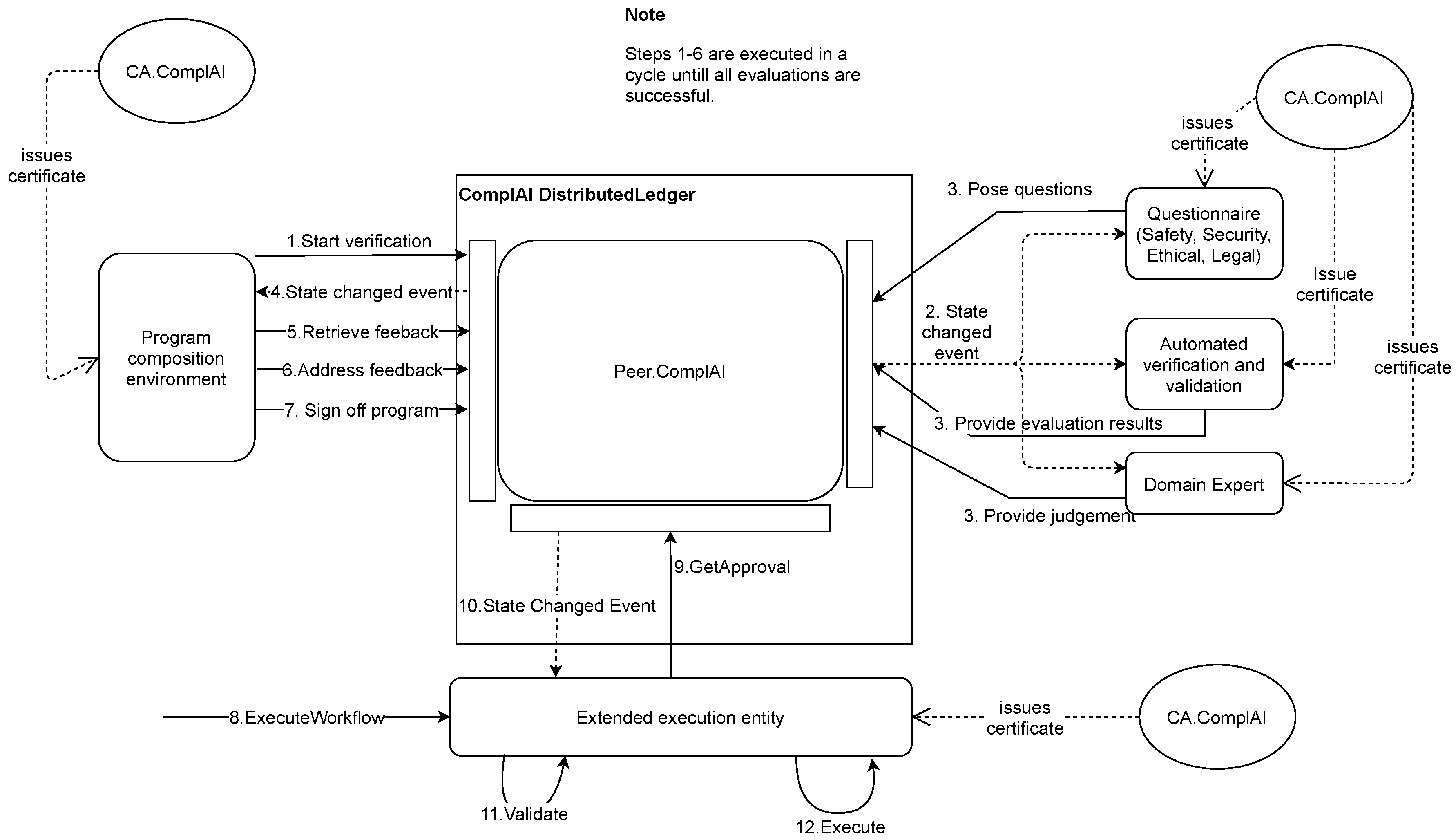
For the complAI environment we use the open source framework HyperLedger Fabric (https://www.hyperledger.org/use/fabric), which provides a distributed ledger software package including the necessary tools for setting up the environment appropriately. In this context, the information shared by the peers is grouped in channels which ensures privacy of sensitive information. The channel access can be restricted by the use of certificates. Every channel consists of world state which is serialized and stored in a database and a block chain which stores the transactions committed on the state. Later modification on past transaction entries lead to an invalid block chain and can be recognized by each peer which guarantees data integrity. Furthermore, the transactions contain a digital signature of the issuer which ensures authenticity on the one hand and non-repudiation on the other hand. In addition to that, participants can initiate smart contracts in order to agree on how the ledger state can be modified. A smart contract defines an asset which the participants can work on as well as methods which can be called when committing a transaction on the ledger. If a peer whats to execute a transaction, it first has to be endorsed by a set of channel peers. If the endorsement policy is fulfilled the transaction is sent to an orderer node which defines an order of incoming transactions and stores them into blocks for the transaction block chain. After that, the block is sent out to each peer which then store the block in their replication of the transaction block chain. Figure 11 shows a concept for a distributed ledger for the complAI environment.
Again, we have the client and the robot as actors along with a verification system. The picture in Figure 11 provides a logical view on the complAI distributed ledger, which means that channel state, contracts and block chain are illustrated as shared information within a channel. Additionally, each participating entity has a peer node operating on the channel. These nodes serve as an entry point for client application which want to operate on the ledger. Up to now four entities were identified during the design process:
- The Design Environment:
- What the client uses to compose the robot application
- The Execution Environment:
- The extended execution entitity as presented in this work
- The Compliance Environment itself:
- with
- The ComplAIController responsible for setting up the ledger and running the orderer node
- The Verification Entity responsible for for verifying workflows in terms of ethical, legal safety and security aspects
Each entity has its own Certificate Authority in order to issue access rights to external clients and additional peers if necessary. The verification process (as illustrated in Figure 12) of a robot program is implemented in form of a smart contract which is installed on the channel. When a new development is started, a new channel is opened. During the composition of the application, the verification environment provides the developer with supporting information on the requirements. This can be drawn either from automated verification methods as far as possible or from pre-developed questionnaires or from domain experts that may judge the application (such as typically done in safety certification). Each transaction independent if tool output, questionnaire or expert input is logged within the blockchain infrastructure. As the figure shows, the verification process can be triggered from the program composition environment (part of the client). Then the verification will be performed until all inputs from questionnaire, automated evaluation, and external experts has been addressed. At some point, the application can be approved and it is digitally signed for execution on the robot. The robot verifies that the signature of the workflow is valid and executes it. This part corresponds to the work presented here.
5.3. Conclusions and Future Work
In this work, we presented an architecture to protect the integrity of robot workflows and seal them after they passed verification and validation procedures.
We use a dedicated trusted authority to perform a digital signature of the presented workflows. The robot, before executing a workflow will check the signature and have proof that the transmitted workflow has not been tampered with. It will only execute such workflows.
Our evaluations show that the introduced overhead for integrity preservation is minimal and will not impact a robot in its operation.
The concept here will be integrated into the larger infrastructure for compliant application development presented above to result in a holistic environment for the trusted development of robot application.
However, we want to point out that a single security solution within a system is never sufficient. Also, we highlight that security should part of the whole lifecycle of a robotic product [47] where it is constantly re-evaluated according to the most recent threat situation since there can never be a 100% security guarantee.
As an extension to our current approach, we will also integrate sanitizable signatures [48]. This will allow authorized entities to modify a program after it has been signed by the CSP to a limited extent. This will open up new application use-cases for our approach.
Author Contributions
Conceptualization, B.B. and B.D.; methodology, B.B., B.D.; software, B.B.; validation, B.B.; investigation, B.B., B.D.; data curation, B.B.; writing—original draft preparation, B.B., B.D.; writing—review M.P., S.R.; visualization, B.D., B.B.; project administration, B.D.; funding acquisition, B.D. All authors have read and agreed to the published version of the manuscript.
Funding
This work has been supported by the Austrian Research Promotion Agency in the project complAI under the program “Ideen Lab 4.0” (FFG No. 878804) and by the Austrian Ministry for Climate Action, Environment, Energy, Mobility, Innovation and Technology within the project “Credible & Safe Robot Systems”.
Conflicts of Interest
The authors declare no conflict of interest.
Abbreviations
The following abbreviations are used in this manuscript:
| WFM | Workflow Manager |
| CSP | Compliance Service Provider |
| V&V | Verification and Validation |
References
- Mo, Y.; Sinopoli, B. Integrity Attacks on Cyber-Physical Systems. In Proceedings of the 1st International Conference on High Confidence Networked Systems, HiCoNS’12, Beijing, China, 17–18 April 2012; Association for Computing Machinery: New York, NY, USA, 2012; pp. 47–54. [Google Scholar] [CrossRef]
- IEC. Security for Industrial Automation and Control Systems—Part 4-2: Technical Security Requirements for IACS Components; Standard, International Electrotechnical Commission (IEC): Geneva, Switzerland, 2019. [Google Scholar]
- Biggs, G.; Macdonald, B. A Survey of Robot Programming Systems. In Proceedings of the Australasian Conference on Robotics and Automation, CSIRO, Brisbane, Australia, 1–3 December 2003; p. 27. [Google Scholar]
- Ahmadvand, M.; Pretschner, A.P.; Kelbert, F. A Taxonomy of Software Integrity Protection Techniques. Adv. Comput. 2019, 112, 413–486. [Google Scholar] [CrossRef]
- Billard, A.; Calinon, S.; Dillmann, R.; Schaal, S. Survey: Robot Programming by Demonstration. In Springer Handbook of Robotics; Book winner of 2 PROSE awards (Award for Excellence in Physical Sciences & Mathematics, Award for Engineering & Technology); Springer: Berlin/Heidelberg, Germany, 2008; pp. 1371–1394. [Google Scholar] [CrossRef]
- Heimann, O.; Guhl, J. Industrial Robot Programming Methods: A Scoping Review. In Proceedings of the 2020 25th IEEE International Conference on Emerging Technologies and Factory Automation (ETFA), Vienna, Austria, 8–11 September 2020; Volume 1, pp. 696–703. [Google Scholar] [CrossRef]
- Ritschel, N.; Kovalenko, V.; Holmes, R.; Garcia, R.; Shepherd, D.C. Comparing Block-based Programming Models for Two-armed Robots. IEEE Trans. Softw. Eng. 2020, 1. [Google Scholar] [CrossRef]
- Winterer, M.; Salomon, C.; Köberle, J.; Ramler, R.; Schittengruber, M. An Expert Review on the Applicability of Blockly for Industrial Robot Programming. In Proceedings of the 2020 25th IEEE International Conference on Emerging Technologies and Factory Automation (ETFA), Vienna, Austria, 8–11 September 2020; Volume 1, pp. 1231–1234. [Google Scholar] [CrossRef]
- Dieber, B.; Kacianka, S.; Rass, S.; Schartner, P. Application-level security for ROS-based Applications. In Proceedings of the 2016 IEEE/RSJ International Conference on Intelligent Robots and Systems (IROS 2016), Daejeon, Korea, 9–14 October 2016. [Google Scholar]
- Karaca, M.; Yayan, U. ROS Based Visual Programming Tool for Mobile Robot Education and Applications. arXiv 2020, arXiv:cs.RO/2011.13706. [Google Scholar]
- Dieber, B.; White, R.; Taurer, S.; Breiling, B.; Caiazza, G.; Christensen, H.; Cortesi, A. Penetration Testing ROS. In Robot Operating System (ROS): The Complete Reference (Volume 4); Koubaa, A., Ed.; Springer International Publishing: Cham, Switzerland, 2020; pp. 183–225. [Google Scholar] [CrossRef]
- Konstantinou, C.; Maniatakos, M.; Saqib, F.; Hu, S.; Plusquellic, J.; Jin, Y. Cyber-physical systems: A security perspective. In Proceedings of the 2015 20th IEEE European Test Symposium (ETS), Freiburg, Germany, 25–29 May 2015; pp. 1–8. [Google Scholar] [CrossRef]
- McClean, J.; Stull, C.; Farrar, C.; Mascareñas, D. A Preliminary Cyber-Physical Security Assessment of the Robot Operating System (ROS); Unmanned Systems Technology XV; Karlsen, R.E., Gage, D.W., Shoemaker, C.M., Gerhart, G.R., Eds.; International Society for Optics and Photonics, SPIE: Bellingham, WA, USA, 2013; Volume 8741, pp. 341–348. [Google Scholar] [CrossRef]
- Yousef, K.A.; AlMajali, A.; Ghalyon, S.; Dweik, W.; Mohd, B. Analyzing Cyber-Physical Threats on Robotic Platforms. Sensors 2018, 18, 1643. [Google Scholar] [CrossRef] [PubMed] [Green Version]
- Taurer, S.; Breiling, B.; Svrta, S.; Dieber, B. Case study: Remote attack to disable MiR100 safety. In Proceedings of the First Cybersecurity for Robotics 2019 Conference (CSfR2019), Bilbao, Spain, 11–18 November 2019. [Google Scholar]
- Lacava, G.; Marotta, A.; Martinelli, F.; Saracino, A.; La Marra, A.; Gil-Uriarte, E.; Vilches, V.M. Current Research Issues on Cyber Security in Robotics; Technical report; Consiglio Nazionale delle Ricerche: Rome, Italy, 2020. [Google Scholar]
- Quarta, D.; Pogliani, M.; Polino, M.; Maggi, F.; Zanchettin, A.M.; Zanero, S. An Experimental Security Analysis of an Industrial Robot Controller. In Proceedings of the 2017 IEEE Symposium on Security and Privacy (SP), San Jose, CA, USA, 22–24 May 2017; pp. 268–286. [Google Scholar] [CrossRef] [Green Version]
- Bonaci, T.; Herron, J.; Yusuf, T.; Yan, J.; Kohno, T.; Chizeck, H.J. To Make a Robot Secure: An Experimental Analysis of Cyber Security Threats Against Teleoperated Surgical Robots. arXiv 2015, arXiv:cs.RO/1504.04339. [Google Scholar]
- Vilches, V.M.; Juan, L.U.S.; Dieber, B.; Carbajo, U.A.; Gil-Uriarte, E. Introducing the Robot Vulnerability Database (RVD). arXiv 2019, arXiv:cs.CR/1912.11299. [Google Scholar]
- Maggi, F.; Pogliani, M. Rogue Automation—Vulnerable and Malicious Code in Industrial Programming; Technical report; TrendMicro: Tokyo, Japan, 2020. [Google Scholar]
- Pogliani, M.; Maggi, F.; Balduzzi, M.; Quarta, D.; Zanero, S. Detecting Insecure Code Patterns in Industrial Robot Programs. In Proceedings of the 15th ACM Asia Conference on Computer and Communications Security, ASIA CCS’20, Taipei, Taiwan, 1–5 June 2020; Association for Computing Machinery: New York, NY, USA, 2020; pp. 759–771. [Google Scholar] [CrossRef]
- Adi, W. Mechatronic Security and Robot Authentication. In Proceedings of the 2009 Symposium on Bio-Inspired Learning and Intelligent Systems for Security, Edingburgh, UK, 20–21 August 2009; pp. 77–82. [Google Scholar] [CrossRef] [Green Version]
- DiLuoffo, V.; Michalson, W.R.; Sunar, B. Robot Operating System 2: The need for a holistic security approach to robotic architectures. Int. J. Adv. Robot. Syst. 2018, 15, 1729881418770011. [Google Scholar] [CrossRef]
- Dieber, B.; Breiling, B.; Taurer, S.; Kacianka, S.; Rass, S.; Schartner, P. Security for the Robot Operating System. Robot. Auton. Syst. 2017, 98, 192–203. [Google Scholar] [CrossRef]
- Mayoral-Vilches, V.; Pinzger, M.; Rass, S.; Dieber, B.; Gil-Uriarte, E. Can ROS be used securely in industry? Red teaming ROS-Industrial. arXiv 2020, arXiv:cs.RO/2009.08211. [Google Scholar]
- Vilches, V.M.; Kirschgens, L.A.; Calvo, A.B.; Cordero, A.H.; Pisón, R.I.; Vilches, D.M.; Rosas, A.M.; Mendia, G.O.; Juan, L.U.S.; Ugarte, I.Z.; et al. Introducing the Robot Security Framework (RSF), a standardized methodology to perform security assessments in robotics. arXiv 2019, arXiv:cs.CR/1806.04042. [Google Scholar]
- Dieber, B.; Breiling, B. Security considerations in modular mobile manipulation. In Proceedings of the 3rd International Conference on Robotic Computing, Naples, Italy, 25–27 February 2019; IEEE: Naples, Italy, 2019; pp. 70–77. [Google Scholar] [CrossRef]
- European Commission. Highl-Level Experts Group on Artificial Intelligence; Ethics guidelines for trustworthy AI; Technical report; European Commission: Brussels, Belgium, 2019. [Google Scholar]
- Murphy, R.; Woods, D.D. Beyond Asimov: The Three Laws of Responsible Robotics. IEEE Intell. Syst. 2009, 24, 14–20. [Google Scholar] [CrossRef]
- Heyer, C. Human-robot interaction and future industrial robotics applications. In Proceedings of the 2010 IEEE/RSJ International Conference on Intelligent Robots and Systems, Taipei, Taiwan, 18–22 October 2010; pp. 4749–4754. [Google Scholar] [CrossRef]
- Kacianka, S.; Pretschner, A. Understanding and Formalizing Accountability for Cyber-Physical Systems. In Proceedings of the 2018 IEEE International Conference on Systems, Man, and Cybernetics (SMC), Miyazaki, Japan, 7–10 October 2018; pp. 3165–3170. [Google Scholar] [CrossRef] [Green Version]
- Ibrahim, A.; Kacianka, S.; Pretschner, A.; Hartsell, C.; Karsai, G. Practical Causal Models for Cyber-Physical Systems; NASA Formal Methods; Badger, J.M., Rozier, K.Y., Eds.; Springer International Publishing: Cham, Switzerland, 2019; pp. 211–227. [Google Scholar]
- Warren, D.R. A Device for Assisting Investigation into Aircraft Accidents; Technical report; Aeronautical Research Laboratories: Columbus, OH, USA, 1954. [Google Scholar]
- Taurer, S.; Dieber, B.; Schartner, P. Secure data recording and bio-inspired functional integrity for intelligent robots. In Proceedings of the 2018 IEEE/RSJ International Conference on Intelligent Robots and Systems (IROS 2018), Madrid, Spain, 1–5 October 2018. [Google Scholar]
- White, R.; Caiazza, G.; Cortesi, A.; Cho, Y.I.; Christensen, H.I. Black Block Recorder: Immutable Black Box Logging for Robots via Blockchain. IEEE Robot. Autom. Lett. 2019, 4, 3812–3819. [Google Scholar] [CrossRef] [Green Version]
- Guerrero-Higueras, Á.M.; Rodríguez-Lera, F.J.; Martín-Rico, F.; Balsa-Comerón, J.; Matellán-Olivera, V. Accountability in Mobile Service Robots. In Advances in Physical Agents; Fuentetaja Pizán, R., García Olaya, Á., Sesmero Lorente, M.P., Iglesias Martínez, J.A., Ledezma Espino, A., Eds.; Springer International Publishing: Cham, Switzerland, 2019; pp. 242–254. [Google Scholar]
- Rodríguez-Lera, F.J.; Guerrero-Higueras, Á.M.; Martín-Rico, F.; Gines, J.; Sierra, J.F.G.; Matellán-Olivera, V. Adapting ROS Logs to Facilitate Transparency and Accountability in Service Robotics. In Robot 2019: Fourth Iberian Robotics Conference; Silva, M.F., Luís Lima, J., Reis, L.P., Sanfeliu, A., Tardioli, D., Eds.; Springer International Publishing: Cham, Switzerland, 2020; pp. 587–598. [Google Scholar]
- Rodríguez-Lera, F.J.; González Santamarta, M.Á.; Guerrero, Á.M.; Martín, F.; Matellán, V. Traceability and Accountability in Autonomous Agents. In Proceedings of the 13th International Conference on Computational Intelligence in Security for Information Systems (CISIS 2020), Burgos, Spain, 16–18 September 2020; Herrero, Á., Cambra, C., Urda, D., Sedano, J., Quintián, H., Corchado, E., Eds.; Springer International Publishing: Cham, Switzerland, 2021; pp. 295–305. [Google Scholar]
- Merkle, R.C. A Certified Digital Signature. In Proceedings of the Advances in Cryptology—CRYPTO’ 89 Proceedings, Santa Barbara, CA, USA, 20–24 August 1990; Springer: New York, NY, USA, 1990; pp. 218–238. [Google Scholar]
- Kuszmaul, J. Verkle Trees; Technical report; Massachusets Institute of Technology: Cambridge, MA, USA, 2018. [Google Scholar]
- Garrido-Jurado, S.; Munoz Salinas, R.M.; Madrid-Cuevas, F.; Marín-Jiménez, M. Automatic generation and detection of highly reliable fiducial markers under occlusion. Pattern Recognit. 2014, 47, 2280–2292. [Google Scholar] [CrossRef]
- Haspl, T.; Breiling, B.; Dieber, B.; Pichler, M.; Breitenhuber, G. Flexible industrial mobile manipulation: A software perspective. In Proceedings of the OAGM & ARW Joint Workshop 2019, Steyr, Austria, 9–10 May 2019. [Google Scholar] [CrossRef]
- Weyrer, M.; Brandstötter, M.; Mirkovic, D. Intuitive Hand Guidance of a Force-Controlled Sensitive Mobile Manipulator. In Proceedings of the IFToMM Symposium on Mechanism Design for Robotics, Udine, Italy, 11–13 August 2019; Gasparetto, A., Ceccarelli, M., Eds.; Springer International Publishing: Cham, Switzerland, 2019; pp. 361–368. [Google Scholar]
- Weyrer, M.; Brandstötter, M.; Husty, M. Singularity Avoidance Control of a Non-Holonomic Mobile Manipulator for Intuitive Hand Guidance. Robotics 2019, 8, 14. [Google Scholar] [CrossRef] [Green Version]
- Abood, O.G.; Elsadd, M.A.; Guirguis, S.K. Investigation of cryptography algorithms used for security and privacy protection in smart grid. In Proceedings of the 2017 Nineteenth International Middle East Power Systems Conference (MEPCON), Cairo, Egypt, 19–21 December 2017; pp. 644–649. [Google Scholar] [CrossRef]
- Buchanan, W.J.; Li, S.; Asif, R. Lightweight cryptography methods. J. Cyber Secur. Technol. 2017, 1, 187–201. [Google Scholar] [CrossRef] [Green Version]
- Mayoral-Vilches, V.; García-Maestro, N.; Towers, M.; Gil-Uriarte, E. DevSecOps in Robotics. arXiv 2020, arXiv:cs.RO/2003.10402. [Google Scholar]
- Ateniese, G.; Chou, D.H.; de Medeiros, B.; Tsudik, G. Sanitizable Signatures. In Proceedings of the Computer Security—ESORICS 2005, Milan, Italy, 12–14 September 2005; di Vimercati, S.C., Syverson, P., Gollmann, D., Eds.; Springer: Berlin/Heidelberg, Germany, 2005; pp. 159–177. [Google Scholar]
Figure 1.
The simplified flow of robot application development from user requirements to execution.

Figure 2.
Compliance architecture: A client wants to execute a workflow or a queue of workflows. It requires a signature of the compliance service. With its signature, the workflows are sealed. Upon execution, the authorization is verified by the authorization handler which also validates the signature. Only if both checks are successful, the workflow is passed on for execution. Numbers in round brackets show the order of steps in the process.

Figure 3.
The communication from the start of program design until execution. The extended execution entity includes the execution entity, the execution controller as well as the authorization handler. The box annotated with “opt” is an optional step, “alt” marks alternatives, one of which must be chosen.

Figure 4.
Constructing a signed workflow description from a given workflow queue.

Figure 5.
The CHIMERA mobile manipulator.

Figure 6.
Steps from the use-case workflow. Scanning the tag (a) The arm is an a position where the wrist cam can scan for the Aruco tag that is fastened of the material rack (workflow step 3.1/3.2 in Table 1). and moving to the according picking position (b) From the tag pose, the robot calculates the pose of the pickup positions and moves the arm there (workflow step 3.4 in Table 1).

Figure 7.
A logical overview of the CHIMERA software stack.

Figure 8.
A C4 architecture diagram of our implementation of the compliance concept. Rounded rectangles describe entities as containers or components. Text in square brackets give technology information. Numbers in round brackets indicate the sequence of calls.
Figure 8.
A C4 architecture diagram of our implementation of the compliance concept. Rounded rectangles describe entities as containers or components. Text in square brackets give technology information. Numbers in round brackets indicate the sequence of calls.

Figure 9.
Client implementation in Node-RED.

Figure 10.
Benchmark results.

Figure 11.
The distributed ledger architecture of the compliant development and execution environment.
Figure 11.
The distributed ledger architecture of the compliant development and execution environment.

Figure 12.
A simplified flow of the development within the complAI environment.


Table 1.
The use-case workflow. Workflows can be re-used with different parameters.
| Wf No. | Wf Description | StepId | Action |
|---|---|---|---|
| 1 | Initialize robot | 1.1 | Move arm to safe transport pose, activate gripper |
| 2 | Move to pickup | 2.1 | Move to pickup location (mobile base) |
| 3 | Find target pose | 3.1 | Move arm to scan pose |
| 3.2 | Scan for Aruco Tags (wrist camera) | ||
| 3.3 | Calculate target position | ||
| 3.4 | Move arm above target position | ||
| 4 | Pick up | 4.1 | Move arm vertically down |
| 4.2 | Grip | ||
| 4.3 | Move arm vertically up | ||
| 5 | Move to robot cargo pose | 5.1 | Move arm above cargo position |
| 6 | Place | 6.1 | Move arm above placement position |
| 6.2 | Move arm vertically down | ||
| 6.3 | Open gripper | ||
| 7 | Move to transport pose | 7.1 | Move arm to safe transport pose |
| 2 | Move to target location | 2.1 | Move to target location, same as above, parameters vary |
| 5 | Move to robot cargo pose | 5.1 | Move arm above cargo position |
| 4 | Pick up | 4.1–4.3 | As above, parameters vary |
| 3 | Find target pose | 3.1–3.4 | Move arm to scan pose |
| 6 | Place | 6.1–6.3 | Place item, as above, parameters vary |
| 7 | Move to transport pose | 7.1 | Move arm to safe transport pose |
Table 2.
GRPC signing service—Transmitted data depending on the queue size.
| Queue Size | Request Data [Byte] | Response Data [Byte] |
|---|---|---|
| 1 | 5154 | 515 |
| 2 (Use Case) | 10,308 | 515 |
| 4 | 20,616 | 515 |
| 8 | 41,232 | 515 |
| 16 | 82,464 | 515 |
| 32 | 164,928 | 515 |
Table 3.
Benchmark results of the workflow queue signature generation process.
| Queue Size | Mean Time Consumption [s] | Allocated Memory [KB] |
|---|---|---|
| 1 | 111 | 16.59 |
| 2 (Use Case) | 135 | 32.97 |
| 4 | 178 | 65.77 |
| 8 | 265 | 131.42 |
| 16 | 451 | 262.86 |
| 32 | 796 | 525.98 |
Table 4.
Benchmark results of the workflow queue signature verification process.
| Queue Size | Mean Time Consumption [s] | Allocated Memory [KB] |
|---|---|---|
| 1 | 20 | 18.13 |
| 2 (Use Case) | 44 | 34.52 |
| 4 | 91 | 67.3 |
| 8 | 175 | 132.95 |
| 16 | 257 | 264.39 |
| 32 | 708 | 527.51 |
Table 5.
Complexity of the overall data flow according to Figure 4. n is the size of the workflow queue, m is the number of workflows available on the execution entity.
Table 5.
Complexity of the overall data flow according to Figure 4. n is the size of the workflow queue, m is the number of workflows available on the execution entity.
| Operation | Complexity | Agent |
|---|---|---|
| Fetching m workflow descriptions (if necessary) | Execution Entity | |
| Constructing a WorkflowQueueSigningRequest | Client | |
| Building the Merkle tree | Compliance Service | |
| Signing the root of the tree | Compliance Service | |
| Constructing a WorkflowQueueSignatureVerificationRequest | Execution Entity | |
| Building the Merkle tree | Compliance Service | |
| Verifying the signature against the Merkle tree root | Compliance Service |
Publisher’s Note: MDPI stays neutral with regard to jurisdictional claims in published maps and institutional affiliations. |
© 2021 by the authors. Licensee MDPI, Basel, Switzerland. This article is an open access article distributed under the terms and conditions of the Creative Commons Attribution (CC BY) license (http://creativecommons.org/licenses/by/4.0/).
Share and Cite
MDPI and ACS Style
Breiling, B.; Dieber, B.; Pinzger, M.; Rass, S. A Cryptography-Powered Infrastructure to Ensure the Integrity of Robot Workflows. J. Cybersecur. Priv. 2021, 1, 93-118. https://0-doi-org.brum.beds.ac.uk/10.3390/jcp1010006
AMA Style
Breiling B, Dieber B, Pinzger M, Rass S. A Cryptography-Powered Infrastructure to Ensure the Integrity of Robot Workflows. Journal of Cybersecurity and Privacy. 2021; 1(1):93-118. https://0-doi-org.brum.beds.ac.uk/10.3390/jcp1010006
Chicago/Turabian StyleBreiling, Benjamin, Bernhard Dieber, Martin Pinzger, and Stefan Rass. 2021. "A Cryptography-Powered Infrastructure to Ensure the Integrity of Robot Workflows" Journal of Cybersecurity and Privacy 1, no. 1: 93-118. https://0-doi-org.brum.beds.ac.uk/10.3390/jcp1010006