A Model Study of a Homogeneous Light-Water Thorium Reactor


Dipartimento di Chimica, Università di Torino, Via P. Giuria 7, 10125 Torino, Italy
Physics 2020, 2(2), 171-183; https://0-doi-org.brum.beds.ac.uk/10.3390/physics2020011
Submission received: 19 March 2020
/
Revised: 12 May 2020
/
Accepted: 13 May 2020
/
Published: 19 May 2020
(This article belongs to the Section Applied Physics)
Abstract
:This work presents a computational study of a -based homogeneous light-water reactor. Thorium reactors have been proposed as an alternative to the uranium fuel cycle since they exploit both the availability of thorium and its ability to afford fissile uranium isotopes by a sequence of neutron captures. Besides , as a result of the neutron captures, a significant amount of (36.3%) and 6.46% of are formed in the reactor under study. More importantly, the proposed simulation points out the possibility of a continuous withdrawal of the uranium isotopes without compromising the criticality and the power output of the reactor. This withdrawal affords the fissile material for the startup of reactors other than the first one, which requires a one-time only limited amount of fissile material. The significant molar fraction of the (0.17) in the extracted fuel does not pose a limitation on weapon proliferation, as a consequence of its high fission cross section for high-energy neutrons.
1. Introduction
Thorium reactors have been studied as an alternative to uranium-based reactors mainly because thorium is more widely available than uranium [1,2]. In a thorium reactor, the fissile material is obtained by the non-fissile by the sequence of neutron (n) capture and decays
Besides the availability of fuel, other advantages have been suggested, such as the reduced production of heavy actinides, in particular that carries the possibility of nuclear weapon proliferation. The fuel cycle of a thorium based reactor hinges on the fission of and does not contain any , the precursor of . Furthermore, the occurrence of by the reaction on is thought to impede the usage of for nuclear weapons [3] because of the relatively short half-life time () of (68.9 yr) that entails the presence of its hard-gamma emitting daughter (). It is not the purpose of this work to discuss the extensive literature on this topic; interested readers may refer to the excellent review by Ault [4]. Most existing suggestions for the configuration of thorium reactors use molten salts as medium and graphite as a moderator [5,6]. Furthermore, fast reactors simulations have been suggested, either based on molten salts [7,8], lead cooled [9], or water. Among the latter we have a boiling water reactor (BWR) study [10], and pressurized water reactor (PWR) studies based on mixed uranium–plutonium [11] or uranium–thorium [12] fuels. A reduction in power density leading to a reduced temperature of the fuel elements was predicted for a mixed oxide - configuration compared to pure [13]. Furthermore, a reduction of burnable neutron poisons was pointed out for Small Modular Reactors operating on - [14]. However, to the author’s knowledge, no study has been published concerning a light-water PWR based solely on thorium (except for the startup phase, requiring a fissile component). The fissile material is being introduced into the reactor under study only on the first two days, i.e., the startup phase. After that, the reactor produces enough fissile material to support the production of energy. More importantly, the proposed simulation points out the possibility of a continuous withdrawal of the uranium isotopes without compromising neither the criticality nor the power output of the reactor. Thus, the proposed reactor could be exploited as a uranium source for the existing uranium-based reactors in the case the uranium supply would become problematic.
After the few thorium based reactors that have been operating in the past were discontinued, a few programs exist, like the 300 MW Advanced Heavy Water Reactor planned in India, making use of an external feed of plutonium. The THOREX (Thorium–Uranium Extraction) reprocessing cycle has been discussed in [15].
This work develops a model study for a homogeneous thorium reactor in light water with an external feed that needs to be operating only for the first two days after startup. The requirement for the startup of a thorium reactor implies the use of fissile material [16], since is not itself fissile. To this purpose, both and have been used. Instead, this work explores the possibility of using the bred from a thorium reactor operating with continuous reprocessing that would also avoid the necessity of extraction [17].
Since the homogeneous reactor would breed a mixture of , , and , it would be possible in principle to extract the bred uranium isotopes to start up other reactors. Although the abundance and role of the bred uranium isotopes is prominent in thorium reactors, it has non been the subject of many investigations so far. This possibility is being investigated in this paper along with the feasibility of maintaining criticality in the presence of a significant sink for all uranium isotopes. The consequence of the composition of the withdrawn uranium on weapon proliferation is briefly examined. The collected fuel could thus be used to start a new thorium reactor without resorting to uranium enriched in the isotope . In particular, we also want to assess whether the amount of non-fissile in the bred fuel would impair criticality during the startup phase. The reactor would operate at a nearly stationary state with a steady input of .
In the sequence of neutron captures, beta decays, and fissions taking place in the environment of a reactor core, there are many nuclides representing branching points, because alternative processes to neutron capture, such as the reaction, are taking place. In this study, we only take into consideration the main sequence from to . We include the production of because we deem it important to quantify its formation in view of the eventuality of nuclear proliferation applications.
2. Definitions and Methodology
2.1. Modeling Nuclear Processes in the Reactor
In order to determine the feasibility of a continuous withdrawal of uranium isotopes from a thorium-based reactor, it is necessary to have a detailed time evolution of the densities of all nuclides. The model has to include both sources and sinks of the uranium isotopes, along with the necessary control procedures for the neutron flux, aimed to keep the reactor critical and affording the desired power output. After establishing the form of all the rate coefficients, the equations for the time evolution can be formulated in terms of all the relevant densities. In particular, the neutron density (or equivalently the flux) needs to be evaluated by detailing all its source, sink, and transport terms. The neutron diffusion term (D is the diffusion coefficient and the Laplacian operator), describing the changes in neutron density as a function of time and space, can be simplified by approximating the neutron depletion in the reactor volume as homogeneous, and due to the neutron flux across the surface. In this way, the time derivative of the neutron density, determined by the neutron flux at the reactor boundary, can in turn be evaluated by solving the spatial eigenvalue equation for neutron density along with the Neumann boundary condition. This procedure allows the problem to be formulated as a system of ordinary differential equations.
Considering a system of nuclei and neutrons (with energy , velocity , in the center of mass reference frame, and volume V) with reduced mass m and giving a reaction with energy-dependent cross section , the corresponding rate coefficient for the process involving thermal neutrons would have the form , that is
where the second equality is obtained by defining (k being the Boltzmann constant and T the temperature). The quantities and represent the density of translational states and the DeBroglie wavelength, respectively,
(h is the Planck constant). We take into consideration the following reactions and decays,
plus the elastic scattering of thermal neutrons by and . All rate coefficients for decay are indicated with the letter with either an ordering subscript or the subscript “” for the emission of delayed neutrons. The rate coefficients for neutron-nuclei interactions are indicated by , with the subscript f for “fission”, c for “capture” by heavy nuclei, and x for the neutron capture by either the fission products or the control neutron absorber. We use the reference density of metallic thorium to define the reduced densities as , being the number density. We follow the convention used in the Manhattan project, indicating the reduced density with the first lowercase letter of the element symbol, its subscript being the last digit of the atomic number (i) and the last digit of the mass number (j) [18]. For example, the reduced density of , , and are noted as , , and , respectively. The same indexes label the various sources and sinks s. We use for the reduced density of neutrons the same symbol used for neutrons, n, and the fission fragments in Equations (4)–(16) are indicated as FF. Since the rate coefficients in processes (4)–(16) can be calculated from known data, we may write a set of differential equations for the time evolution of the species, once the initial conditions for the number density for all species are specified. In the non-dimensional time unit , the evolution of the homogeneous system for reactions (4)–(16) is given by the equations
with the dot indicating the derivative with respect to , and
, and the parameters given in Table 1. The variable h indicates the reduced density of and the variable f indicates the reduced number density of the fission fragments, while the same letter as a subscript indicates fission.
The parameters and represent the net number of the prompt and delayed neutrons emitted after fission, respectively [19]. In Equation (25) we summarize the effect of the neutron absorber (obeying the equation , the source term being subject to a feedback control to keep the power output at the desired level) with the neutron poison fission products y, exhibiting a high cross section for neutron capture (as and , having total a fission yield of 0.074 and obeying the equation ). Representing all neutron absorbers by the single variable x and the absorption cross section , and summing these two equations we obtain Equation (25).
In the conventional time and density units, the diffusion coefficient for neutrons may be expressed through the diffusion length as
with
The subscript refers to the elastic scattering of neutrons. Defining , and expressing in terms of the reduced parameters we have
The reduced diffusion coefficient thus is
Neglecting the contribution to the neutron flux of both the source and the delayed neutrons in Equation (24), we have:
Assuming constant coefficients, a solution of the form [20], and separating the variables, we obtain the time equation
with solution
the spatial eigenvalue equation
with the Neumann boundary condition [21]
and solution
The quantity in Equation (40) is the transport length given by
The constant C was chosen to match the initial conditions for a homogeneous neutron number density in a spherical reactor of radius R
that gives
If we approximate the time derivative of the neutron density in the whole volume in terms of the instantaneous flux at the boundary , as , and express according to Equation (45) as
where , the the time derivative of the neutron reduced density becomes , and, in non-dimensional units.
2.2. Simulation Details
The actual value of is obtained iteratively by solving Equation (46) for at the end of a simulation, and use this value back in Equation (49) until self consistency is reached. To validate the approximation given by Equation (48), we report in Table 2 the fairly stable values of , , and at different times during a simulation.
For , we can look for a stationary solution of the system of the Equations (17)–(26). The stationary reduced densities of the system (17)–(26) (denoted with a bar) are as follows
with
Defining the ratio z between the power density at time t and the required value for the power density ,
(the average recoverable energy per fission being [19]), the condition at gives
We thus have stationary values for all state variables (except x and ) in terms of the value of and . To obtain , we equate the expression for in Equations (49) and (27) and solve for x. Since is also a function of x through the term , that in turns depends on x because of , , , and , this operation must be done iteratively. Once is known, Equation (25) affords the value of . We actually do not find positive solutions for both and unless R is very large (), but nevertheless the above expressions turn out to be useful approximations to a true stationary state.
The values of all state variables are given in Table 3 for a reactor with a stationary source of (); the corresponding burnup rates and fractional power are given in Table 4. The processed uranium with the composition given in Table 3 corresponds to the molar fractions , , and for , , and , respectively.
In reality, a proper stationary-state does not exist for realistic values of R. However, a pseudo-steady state can be attained: i.e., a state where all the values of the state variables change on a time scale much longer than the typical reactor operation time. For example, 5 years after startup, we have , , , and .
We now address the issue of providing the fissile material to start a reactor. We begin by observing that, by including a sink of uranium of the form , where and , the stationary point of the system (17)–(26) (denoted by ) satisfies the nonlinear system of equations
with the corresponding expression for the stationary source being
Since we do not have the option to actually operate the sink at the true stationary point, the actual expression used for the sink is
and the composition of the extracted uranium fuel is given by integration over time of the sink term
The solution of the system of Equations (60)–(62) is obtained by iteration until the composition given by Equation (65) converges to a stable value. We thus have the option of running the reactor while withdrawing, for example by continuous processing, the fissile material necessary to start a new reactor, with fuel of composition given by Equation (65).
3. Results and Discussion
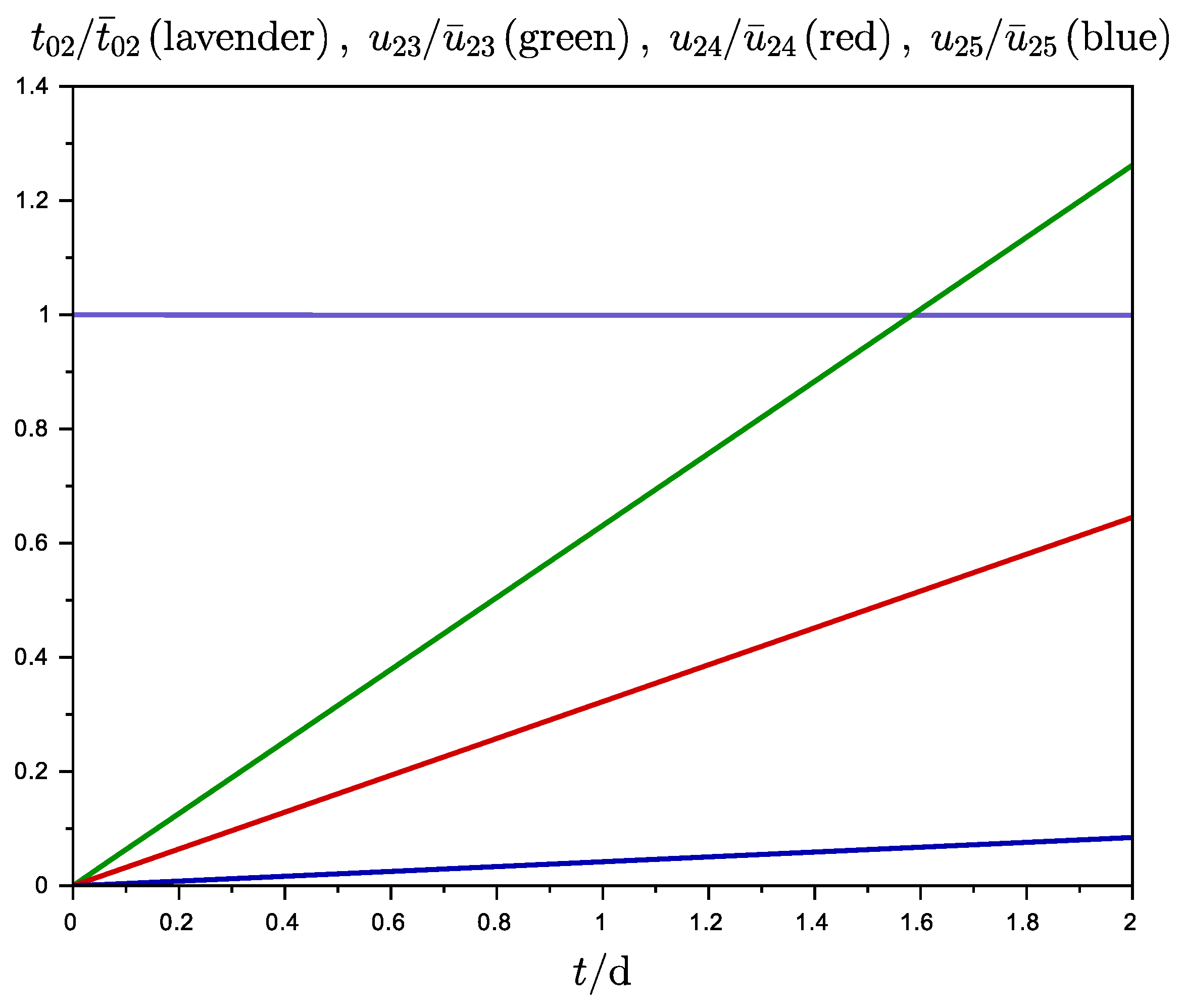
We begin detailing the results of this computational study [22] with a simulation of the reactor with a startup phase of , where each individual source of uranium is set to the value , matching the composition given by Equation (65) and totaling . At the end of the startup phase, the amount of uranium put into the reactor is , and the uranium source is switched off. The ratio of the reduced density of the uranium species to the corresponding pseudo-stationary density is plotted in Figure 1 during the startup phase.
The corresponding reduced density of equals its initial value , equivalent to . This value corresponds to the concentration of , within the limits of thorium nitrate solubility in water given in [23] as for °C. The reduced density of hydrogen, assumed to be constant, is equal to 1.07. All values of the state variables are given as ratios to the pseudo-stationary state densities with at the power density . In the two-day startup run with , the maximum value of () corresponds to . The growth of the reduced density of all uranium isotopes is linear, an indication that the source term is always dominant with respect to the fission rates.
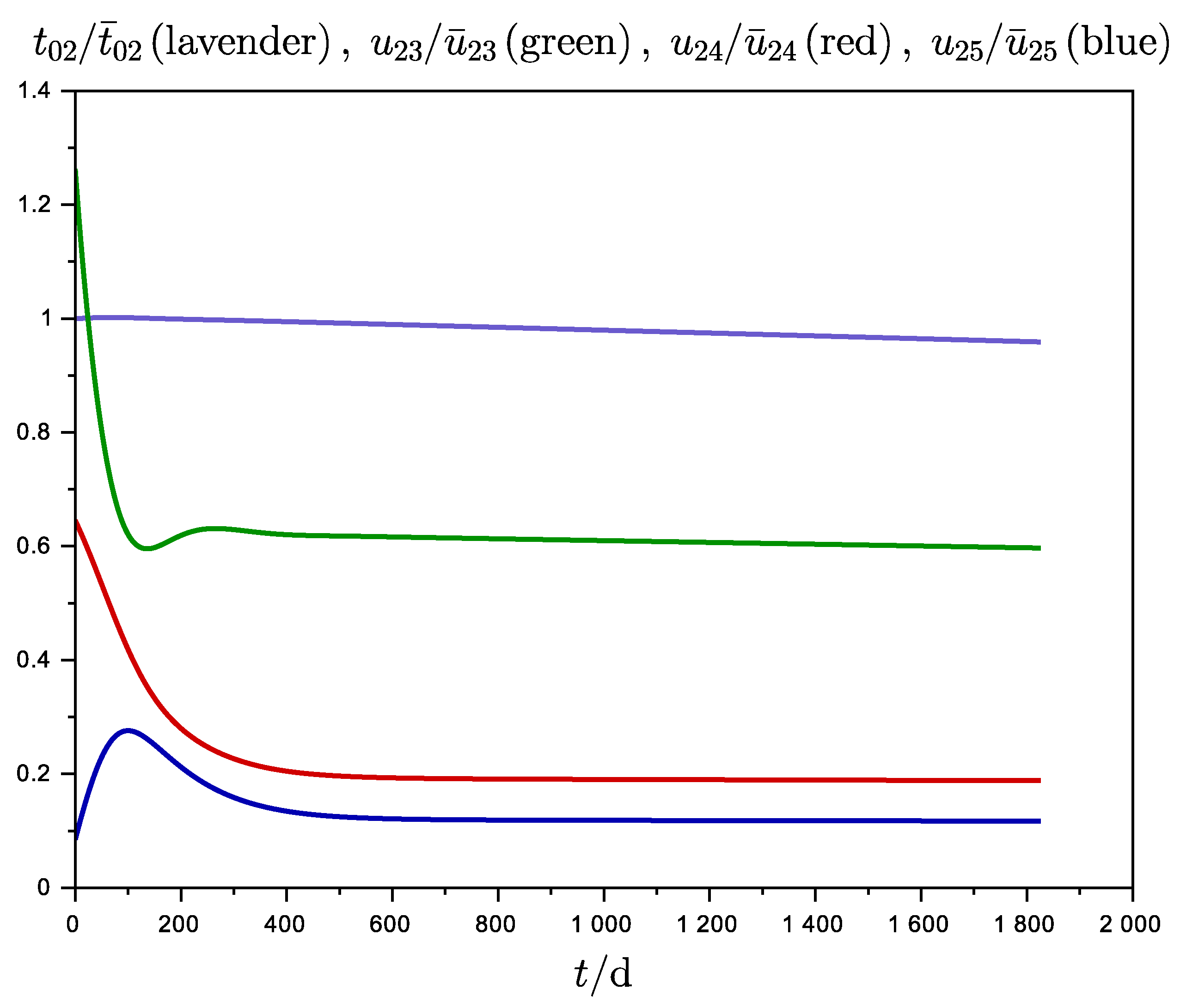
After the two-day startup the uranium source was switched off and the value of the source of was dynamically assigned based on the ratio z of the current power density to the set power density, i.e., . The ratios of the reduced densities of the uranium species to the corresponding pseudo-steady-state density are reported in Figure 2 for a period of 5 years, and the value of the average neutron flux in this time period is .
The reduced density of at the time of switch-off of the uranium source is ≈ above its stationary value, while the other isotopes, and , reach the equilibrium value just at the end of the 5-yr time period.
Operating the uranium sink for a period of 5 years the system stays critical by increasing the neutron flux to and lowering the uranium state variables to the values given in Table 7. Plots of the ratios of the reduced densities of the various species to the corresponding pseudo-steady-state density are reported in Figure 3. The withdrawn uranium has the composition , corresponding to the molar fractions , and for , , and , respectively. At these molar ratios and the number density of metallic uranium , the fission rate per fast neutron would be , and for , , and , respectively. All these values are able to sustain a fission chain reaction in a metallic uranium sphere with the above isotopic composition. The corresponding ratios between the reduced densities at the end of the five years and the pseudo-steady state reduced densities of uranium are , , and . The withdrawal of the uranium isotopes reduces the reduced density of to of its initial value.
Based on a cross section of for the reaction on by neutrons [3], the formation of in a period of five years through the channel gives , corresponding to a specific activity of in the processed uranium with the composition of the withdrawn fuel. Kang and von Hippel estimated the exposure at a distance of one meter from a 5 kg uranium sphere with 0.4 % of in secular equilibrium with to be . The other uranium isotopes would contribute a specific activity of , , and for , , and respectively. For comparison, the specific activity of is .
The ratio of the total uranium input at the end of the two-day startup period to the uranium sink rate of a reactor with at the end of the five-year period following startup is , that is, a reactor running with a uranium sink for would breed enough uranium to start a new reactor of the same size in 2 days.
We conclude by comparing the yield of this simulated reactor with the more common reactors based on the uranium fuel cycle. The ratio of the fissioned mass to the energy produced for the homogeneous reactor described above as , while the corresponding value for the fission of enriched at is .
4. Conclusions
This work explores the possibility of energy production by a fission reactor in the absence of a continuous supply of fissile isotopes, since the dynamics of a homogeneous light-water thorium reactor can be exploited for breeding the uranium isotopes necessary for fission. In fact, after a short startup period of two days requiring fissile uranium isotopes (for a total inventory of ), the modeled reactor can operate at a nearly steady state with a constant source of , both with and without a uranium sink, i.e., a steady withdrawal of all uranium isotopes. After the fissile or has been used for the startup of the first reactor, its operation with a continuous uranium sink for 0.72 yr can afford the necessary fissile uranium isotopes to start a new reactor, allowing the continuous production of energy from only . However, the limitation to nuclear weapon proliferation does not appear to be ensured by the molar fraction of in the extracted uranium fuel.
Funding
This research received no external funding.
Conflicts of Interest
The author declares no conflict of interest.
References
- Jordan, B.W.; Eggert, R.G.; Dixon, B.W.; Carlsen, B.W. Thorium: Crustal abundance, joint production, and economic availability. Resour. Policy 2015, 44, 81–93. [Google Scholar] [CrossRef] [Green Version]
- Lung, M.; Gremm, O. Perspectives of the thorium fuel cycle. Nucl. Eng. Des. 1998, 180, 133–146. [Google Scholar] [CrossRef]
- Kang, J.; von Hippel, F.N. U-232 and the Proliferation-Resistance of U-233 in Spent Fuel. Sci. Glob. Secur. 2001, 9, 1–32. [Google Scholar] [CrossRef]
- Ault, T.; Krahn, S.; Croff, A. Thorium fuel cycle research and literature: Trends and insights from eight decades of diverse projects and evolving priorities. Ann. Nucl. Energy 2017, 110, 726–738. [Google Scholar] [CrossRef]
- Furukawa, K.; Arakawa, K.; Berrin Erbay, L.; Ito, Y.; Kato, Y.; Kiyavitskaya, H.; Lecocq, A.; Mitachi, K.; Moir, R.; Numata, H.; et al. A road map for the realization of global-scale thorium breeding fuel cycle by single molten-fluoride flow. Energy Convers. Manag. 2008, 49, 1832–1848. [Google Scholar] [CrossRef]
- Zhou, S.; Yang, W.S.; Park, T.; Wua, H. Fuel cycle analysis of molten salt reactors based on coupled neutronics and thermal-hydraulics calculations. Ann. Nucl. Energy 2018, 114, 369–383. [Google Scholar] [CrossRef]
- Cervi, E.; Lorenzi, S.; Cammi, A.; Luzzi, L. Development of an SP3 neutron transport solver for the analysis of the Molten Salt Fast Reactor. Nucl. Eng. Des. 2019, 346, 209–219. [Google Scholar] [CrossRef]
- Allibert, M.; Merle, E.; Delpech, S.; Gerardin, D.; Heuer, D.; Laureau, A.; Moreau, S. Preliminary proliferation study of the molten salt fast reactor. EPJ Nucl. Sci. Technol. 2020, 6, 5. [Google Scholar] [CrossRef]
- Juárez-Martínez, L.-C.; Francois, J.-L. Comparative neutronic study of homogeneous and heterogeneous thorium fuel based core design in a lead-cooled fast reactor. Ann. Nucl. Energy 2018, 114, 102–109. [Google Scholar] [CrossRef]
- Björk, K.I.; Netterbrant, C. Thorium as an additive for improved neutronic properties in boiling water reactor fuel. Ann. Nucl. Energy 2018, 113, 470–475. [Google Scholar] [CrossRef]
- Tucker, L.P.; Usman, S. Thorium-based mixed oxide fuel in a pressurized water reactor: A burnup analysis with MCNP. Ann. Nucl. Energy 2018, 111, 163–175. [Google Scholar] [CrossRef]
- Oettingen, M. Thorium based fuel loading pattern for PWR reactor. E3S Web Conf. 2019, 108, 1028. [Google Scholar] [CrossRef]
- Maiorino, J.R.; Stefani, G.L.; Moreira, J.M.L.; Rossi, P.C.R.; Santos, T.A. Feasibility to convert an advanced PWR from UO2 to a mixed U/ThO2 core—Part I: Parametric studies. Ann. Nucl. Energy 2017, 102, 47–55. [Google Scholar] [CrossRef]
- Akbari-Jeyhouni, R.; Ochbelagh, D.R.; Maiorino, J.R.; D’Auria, F.; de Stefani, G.L. The utilization of thorium in Small Modular Reactors—Part I: Neutronic assessment. Ann. Nucl. Energy 2018, 120, 422–430. [Google Scholar] [CrossRef]
- Anantharaman, K.; Shivakumar, V.; Saha, D. Utilisation of thorium in reactors. J. Nucl. Mater. 2008, 383, 119–121. [Google Scholar] [CrossRef]
- Barros, G.P.; Pereira, C.; Veloso, M.A.F.; Costa, A.L. Thorium and reprocessed fuel utilization in an accelerator-driven system. Ann. Nucl. Energy 2015, 80, 14–20. [Google Scholar] [CrossRef]
- Nuttin, A.; Heuer, D.; Billebaud, A.; Brissot, R.; Le Brun, C.; Liatard, E.; Loiseaux, J.-M.; Mathieu, L.; Meplan, O.; Merle-Lucotte, E.; et al. Potential of thorium molten salt reactors: Detailed calculations and concept evolution with a view to large scale energy production. Prog. Nucl. Energy 2005, 46, 77–99. [Google Scholar] [CrossRef] [Green Version]
- Serber, R. The Los Alamos Primer; University of California Press: Berkeley, CA, USA; Oxford, UK, 1992; p. 9. [Google Scholar]
- Lamarsh, J.R.; Baratta, A.J. Introduction to Nuclear Engineering, 3rd ed.; Prentice Hall: Upper Saddle River, NJ, USA, 1983; pp. 85–88. [Google Scholar]
- Logan, J. Applied Partial Differential Equations, 2nd ed.; Springer: New York, NY, USA, 2004; p. 121. [Google Scholar]
- Lewis, E.E. Fundamentals of Nuclear Reactor Physics; 30 Corporate Drive, Suite 400; Academic Press: Burlington, MA, USA, 2008; p. 146. [Google Scholar]
- All Calculations Were Performed with the Program Scilab: Scilab Enterprises (2012). Scilab: Free and Open Source Software for Numerical Computation (OS, Version 6.1.0) (Software). Available online: http://www.scilab.org (accessed on 27 February 2020).
- Apelblat, A.; Azoulay, D.; Sahar, A. Properties of aqueous thorium nitrate solutions. J. Chem. Soc. Faraday Trans. 1973, 69, 1618–1623. [Google Scholar] [CrossRef]
Figure 1.
Plots of the ratio of densities at time t (in days) with respect to the corresponding stationary density: (for , lavender), (for , green), (for , red), and (for , blue) versus time. The period is the two-day startup with the uranium source operative for a reactor with radius .
Figure 1.
Plots of the ratio of densities at time t (in days) with respect to the corresponding stationary density: (for , lavender), (for , green), (for , red), and (for , blue) versus time. The period is the two-day startup with the uranium source operative for a reactor with radius .

Figure 2.
Plots of the ratio of densities at time t (in days) with respect to the corresponding stationary density: (for , lavender), (for , green), (for , red), and (for , blue) versus time. The period is five years following the two-day startup of a reactor with radius in the absence of a uranium sink.

Figure 3.
Plots of the ratio of densities at time t (in days) with respect to the corresponding stationary density: (for , lavender), (for , green), (for , red), and (for , blue) versus time. The period is five years following the two-day startup of a reactor with radius in the presence of a uranium sink.


Table 1.
Definitions and values of the non-dimensional parameters. The subscripts refer to the processes: c to neutron capture; x to neutron capture by either the fission products or the control neutron absorber; f to fission; to delayed neutrons; to elastic scattering of neutrons.
Table 1.
Definitions and values of the non-dimensional parameters. The subscripts refer to the processes: c to neutron capture; x to neutron capture by either the fission products or the control neutron absorber; f to fission; to delayed neutrons; to elastic scattering of neutrons.
| Parameter | Definition | Value |
|---|---|---|
| Equation (48) | ||
Table 2.
Quantities involved in the approximation given by Equation (48) during the 5-yr period operating with a uranium sink, with the reactor radius , power density , (≡), , and .
Table 2.
Quantities involved in the approximation given by Equation (48) during the 5-yr period operating with a uranium sink, with the reactor radius , power density , (≡), , and .
| t | |||
|---|---|---|---|
| 30 d | 2.31 | 0.78 | 2.05 |
| 0.25 yr | 2.22 | 0.80 | 2.00 |
| 0.50 yr | 2.23 | 0.79 | 2.02 |
| 1.00 yr | 2.25 | 0.78 | 2.04 |
| 5.00 yr | 2.26 | 0.77 | 2.06 |
Table 3.
Values of the variables for a homogeneous reactor at pseudo-steady state with the reactor radius , power density , (≡), and (≡). The second row is in .
Table 3.
Values of the variables for a homogeneous reactor at pseudo-steady state with the reactor radius , power density , (≡), and (≡). The second row is in .
| 2.34 | 7.21 | 4.59 | 0.82 |
Table 4.
Burnup rates (in ) of , , , and and fractional power output of a homogeneous reactor at pseudo-steady state with (≡), the reactor radius , and power density .
Table 4.
Burnup rates (in ) of , , , and and fractional power output of a homogeneous reactor at pseudo-steady state with (≡), the reactor radius , and power density .
| Nuclide | ||||
|---|---|---|---|---|
| Burning rate | 22.32 | 20.67 | 1.71 | |
| Fractional power | - | 0.924 |
Table 5.
Values of the reduced densities for the isotopes of uranium in a homogeneous reactor at pseudo-steady state running with a uranium sink, the reactor radius , power density , (≡), (≡), and (≡). The second row of data is in .
Table 5.
Values of the reduced densities for the isotopes of uranium in a homogeneous reactor at pseudo-steady state running with a uranium sink, the reactor radius , power density , (≡), (≡), and (≡). The second row of data is in .
| 5.01 | 2.54 | 0.30 |
Table 6.
Burnup rates (in ) of , , , and and fractional power output of a homogeneous reactor at pseudo-steady state with uranium sink, the reactor radius , and power density .
Table 6.
Burnup rates (in ) of , , , and and fractional power output of a homogeneous reactor at pseudo-steady state with uranium sink, the reactor radius , and power density .
| Nuclide | ||||
|---|---|---|---|---|
| Burning rate | ||||
| Fractional power | - |
Table 7.
Reduced number density of the uranium isotopes for a homogeneous reactor at the end a 5-yr period operating with a uranium sink, the reactor radius , power density , (≡), (≡), and (≡). The second row of data is in .
Table 7.
Reduced number density of the uranium isotopes for a homogeneous reactor at the end a 5-yr period operating with a uranium sink, the reactor radius , power density , (≡), (≡), and (≡). The second row of data is in .
| 4.31 | 0.87 |
© 2020 by the author. Licensee MDPI, Basel, Switzerland. This article is an open access article distributed under the terms and conditions of the Creative Commons Attribution (CC BY) license (http://creativecommons.org/licenses/by/4.0/).
Share and Cite
MDPI and ACS Style
Canepa, C. A Model Study of a Homogeneous Light-Water Thorium Reactor. Physics 2020, 2, 171-183. https://0-doi-org.brum.beds.ac.uk/10.3390/physics2020011
AMA Style
Canepa C. A Model Study of a Homogeneous Light-Water Thorium Reactor. Physics. 2020; 2(2):171-183. https://0-doi-org.brum.beds.ac.uk/10.3390/physics2020011
Chicago/Turabian StyleCanepa, Carlo. 2020. "A Model Study of a Homogeneous Light-Water Thorium Reactor" Physics 2, no. 2: 171-183. https://0-doi-org.brum.beds.ac.uk/10.3390/physics2020011