Highly Active Carbon-Based Electrocatalysts for Dye-Sensitized Solar Cells: A Brief Review


1
Department of Chemistry, National Taiwan University, Taipei City 10617, Taiwan
2
Department of Applied Physics and Chemistry, University of Taipei, Taipei City 10048, Taiwan
*
Author to whom correspondence should be addressed.
Physics 2020, 2(3), 412-424; https://0-doi-org.brum.beds.ac.uk/10.3390/physics2030023
Submission received: 23 July 2020
/
Revised: 29 August 2020
/
Accepted: 2 September 2020
/
Published: 8 September 2020
(This article belongs to the Section Applied Physics)
Abstract
:Dye-sensitized solar cells (DSSCs) have emerged as promising alternatives to traditional silicon-based solar cells due to their relatively high conversion efficiency, low cost, flexibility, and environmentally benign fabrication processes. In DSSCs, platinum (Pt)-based materials used as the counter electrode (CE) exhibit the superior catalytic ability toward the reduction reaction of triiodide ions, which are attributed to their excellent catalytic activity and high electrical conductivity. However, Pt-based materials with high cost and limited supply hinder them from mass production. Developing highly active and stable CE materials without noble metals has been a persistent challenge for the practical application in DSSCs. Recently, a number of earth-abundant catalysts, especially carbon-based materials, display high activity, low cost, and good stability that render them attractive candidates to replace Pt in DSSCs. Herein, we will briefly review recent progress on carbon-based electrocatalysts as CEs in DSSC applications. The strategies of improving the catalytic activity of carbon-based materials such as structural engineering and/or heteroatom doping will be introduced. The active sites toward the reduction reaction of triiodide ions summarized from experimental results or theoretical calculation will also be discussed. Finally, the futuristic prospects and challenges of carbon-based electrocatalysts as CEs in DSSCs will be briefly mentioned.
1. Introduction
Dye-sensitized solar cells (DSSCs) have attracted much attention and have made increasing progress since they were first reported in 1991 [1]. Many attractive properties such as low-cost fabrication processes, lightweight, flexible, and good performance in weak light conditions have been demonstrated in DSSCs [2,3,4]. A DSSC consists of three main components: a dye-sensitized titania (TiO2) photoanode, the triiodide (I3−)/iodide (I−) electrolyte solution, and a platinum-coated fluorine-doped tin oxide (FTO) glass as a counter electrode (CE), as shown in Figure 1a [5]. Figure 1b briefly illustrates the energy diagram of a DSSC and the preferred charge transfer pathway. When photons illuminate on adsorbed dye sensitizer, the electrons of dye were excited to lowest unoccupied molecular orbital (LUMO) as shown by the (a) in Figure 1b. Then the electrons were transferred into the conduction band (CB) of the semiconductors (b) and diffuse to the current collector (c). The electrons flow through the external circuit to the cathode (d) where the electrons transfer to the electrolyte (e) and the oxidized electrolyte (I3− ions) are reduced. The electrolyte (I− ions) can regenerate the oxidized dye (f). A circuit circle is completed. The CE is responsible for catalyzing the reduction of I3− ions in the electrolyte solution, which plays a crucial role on the performance of DSSCs. In general, platinum (Pt; the actual material is more precisely Pt/PtOx) exhibits good electrical conductivity and excellent catalytic activity for the reduction of the redox couples [6]. However, its high cost and severe corrosion in triiodide (I3−)/iodide (I−)-based electrolyte solutions are the main concern [7,8]. A good CE has to meet some requirements such as low cost, high conductivity, corrosion resistance, good catalytic activity toward reducing the redox couple, and excellent stability in the electrolyte solution [9]. In order to maximize the performance of DSSCs, the exchange current density (j0) of CE, which is inversely related to charge-transfer resistance (Rct) between CE and electrolyte solution, is described as the below equation:
where R, T, n, F, and Rct are the gas constant, the absolute temperature, the number of transferred electrons, Faraday constant, and charge-transfer resistance at CE/electrolyte solution interface, respectively. Thus, it is obvious that the intrinsic catalytic activity of CE can be evaluated by the Rct value. The Rct is usually measured by the electrochemical impedance spectrum (EIS) with a symmetric configuration (as shown in Figure 1c) to rule out the interference from other components in DSSCs [10,11]. A Nyquist plot as shown in Figure 1d can be figured out by fitting with the equivalent circuit. In Nyquist plot, the semicircle in high-frequency region shows the charge-transfer process in the interface of CE and electrolyte solution, while that in low-frequency region is corresponding to the diffusion process of electrolyte ions. Also, Rs represents the sheet resistance of CE and electrolyte diffusion impedance (ZN).
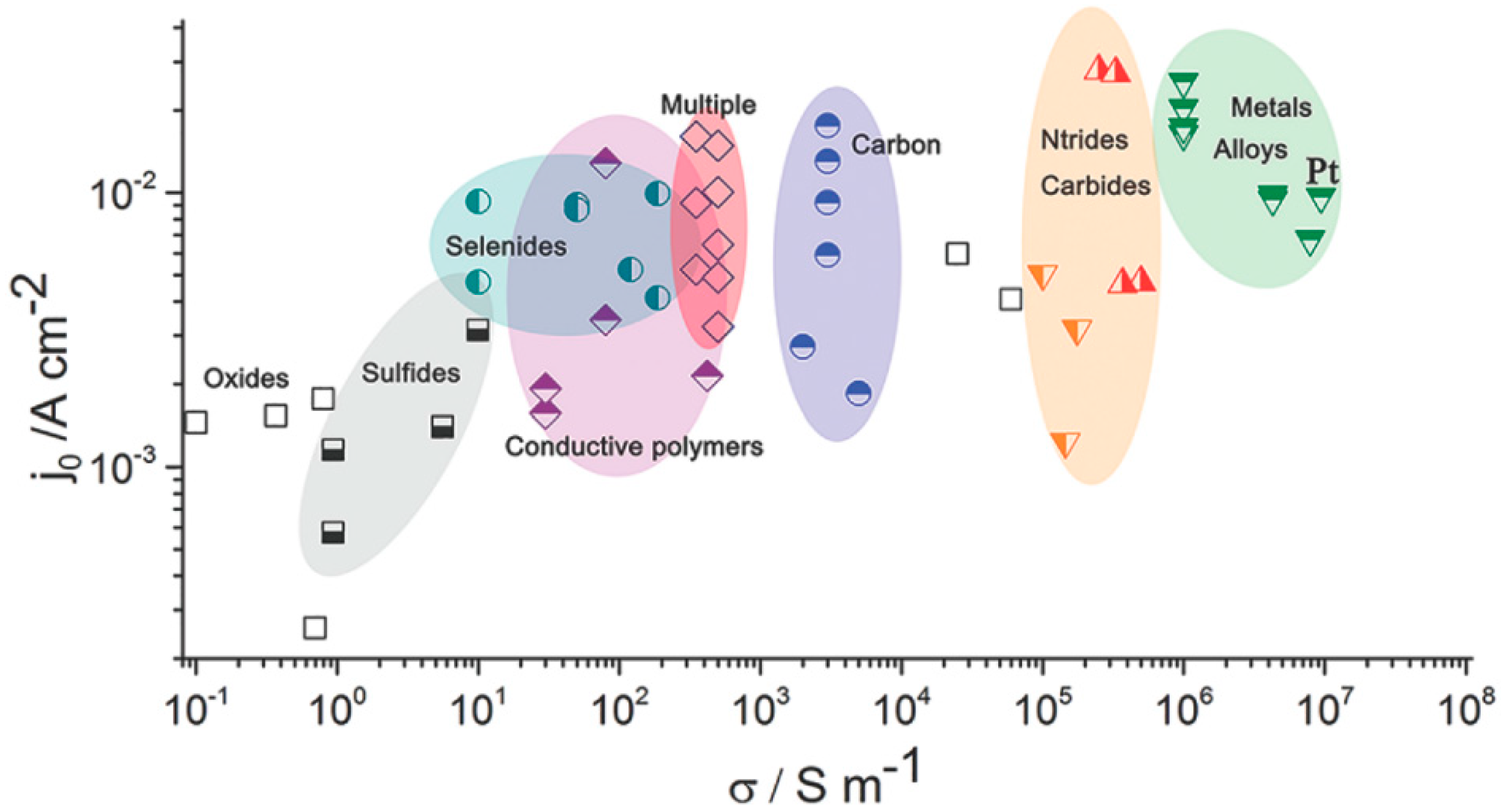
There are many different kinds of novel materials investigated as CE for DSSCs in recent years [12,13,14,15,16,17,18,19]. As mentioned above, the prerequisites to promising CEs are high exchange current density and high electrical conductivity. Figure 2 summarizes the exchange current density of various CEs based on their theoretical conductivity. It is demonstrated that the electrical conductivity of different CEs follow the order of metals and alloys > metal nitrides, metal carbides > carbon materials > multiple compounds > conductive polymers, selenides > sulfides > oxides. Among them, carbon-based materials are low-cost and promising CE materials to replacing Pt. Generally, carbon-based CEs possess sufficient conductivity and high resistance from electrolyte corrosion. However, the transparency of a DSSC is usually limited by the counter electrode, e.g., carbon-based CEs can be less translucent than platinized FTO. Though the CEs’ optical transparency is not mandatory for the proper function of DSSCs, it presents an added benefit for practical modules (i.e., light illumination from both sides of DSSC devices). Fortunately, graphene, one kind of carbon allotropes, exhibits remarkable carrier mobility (>2 × 105 cm2V−1s−1), high optical transparency, and specific surface area (2670 m2/g); those benefits make it be a promising CE material in DSSCs [20]. It has been shown that the specific surface area of carbon-based materials is positively correlated with the exchange current density (j0) or power conversion efficiency (PCE). To further increase the specific surface area and catalytic activity, the structural engineering of graphene to three-dimensional (3D) shape/morphology are efficient routes. It would expose many defects and/or functional groups such as hydroxyl groups (-OH), carbonyl groups (>C=O), and carboxyl groups (-COOH) when the structure of two-dimensional graphene transforms to three dimensions. Increasing the number of defects and/or functional groups leads to an improvement in electrocatalytic activity [21]. On the other hand, the insertion of heteroatoms into the basal plane of graphene is also an efficient way to enhance the intrinsic electrocatalytic activity of graphene, which is much lower than that of Pt [22,23,24].
2. Synthesis of Graphene
Many kinds of preparation methods including electrochemical deposition [25,26], chemical vapor deposition [27,28], doctor blade [29,30], and electrophoretic deposition [31,32] have been investigated for CE preparation in DSSCs. All of the preparation techniques were aimed to achieve high electrocatalytic activity and high conductivity of CE materials. Li et al. [26] reported an all electrochemical strategy to synthesize MoS2/graphene composite films as CEs in DSSCs (Figure 3a). The graphene oxide was electrodeposited and electro-reduced, and then MoS2 was subsequently electrodeposited on reduced graphene oxide layers. The MoS2/graphene composite film as CE exhibited higher electrocatalytic ability toward triiodide reduction reaction due to its 3D structure providing large surface area. Consequently, the DSSCs with optimized MoS2/graphene CEs exhibit a high PCE of 8.01%, which is comparable to 8.21% of DSSCs with Pt CEs. Choi et al. [28] demonstrated a CE using graphene-based multi-walled carbon nanotubes structure. Graphene layers were first drop-casted on a SiO2/Si substrate and multi-walled carbon nanotubes were synthesized on top of graphene layers with iron catalysts by CVD. The graphene-based multi-walled carbon nanotubes (GMWNTs) film was transferred onto the fluorine-doped tin oxide/glass substrate (Figure 3b). The DSSCs with graphene-based multi-walled carbon nanotubes as CE show an efficiency of 3.0% and high fill factor of 69%, suggesting graphene-based multi-walled carbon nanotubes were a promising candidate as the CE material in DSSCs.
The actual DSSC performances achieved by using two-dimensional graphene nanosheets are always less than that expected. The reduced performance is substantially originated from the agglomeration and restacking of graphene nanosheets due to their strong π-π interactions. To solve the problems of graphene restacking, three-dimensional (3D) graphene spheres, and crumples with large surface areas and abundant pores have been designed [33,34,35]. Xue et al. [36] developed one-step CVD synthetic method to prepare 3D graphene-carbon nanotube hollow fibers with radially aligned CNTs (RACNTs) seamlessly sheathed by a cylindrical graphene layer through an anodized aluminum template. These fibers with a controllable surface area, meso-/micropores, and superior electrical properties are an excellent CE in DSSCs. The DSSCs based on these fibers showed a PCE of 6.8% compared to that based on Pt wire CE with a PCE of 2.74%. Additionally, these novel fiber-shaped graphene-RACNT energy conversion devices are so flexible they can be woven into fabrics as power sources.
3. Graphene-Based Counter Electrodes for DSSCs
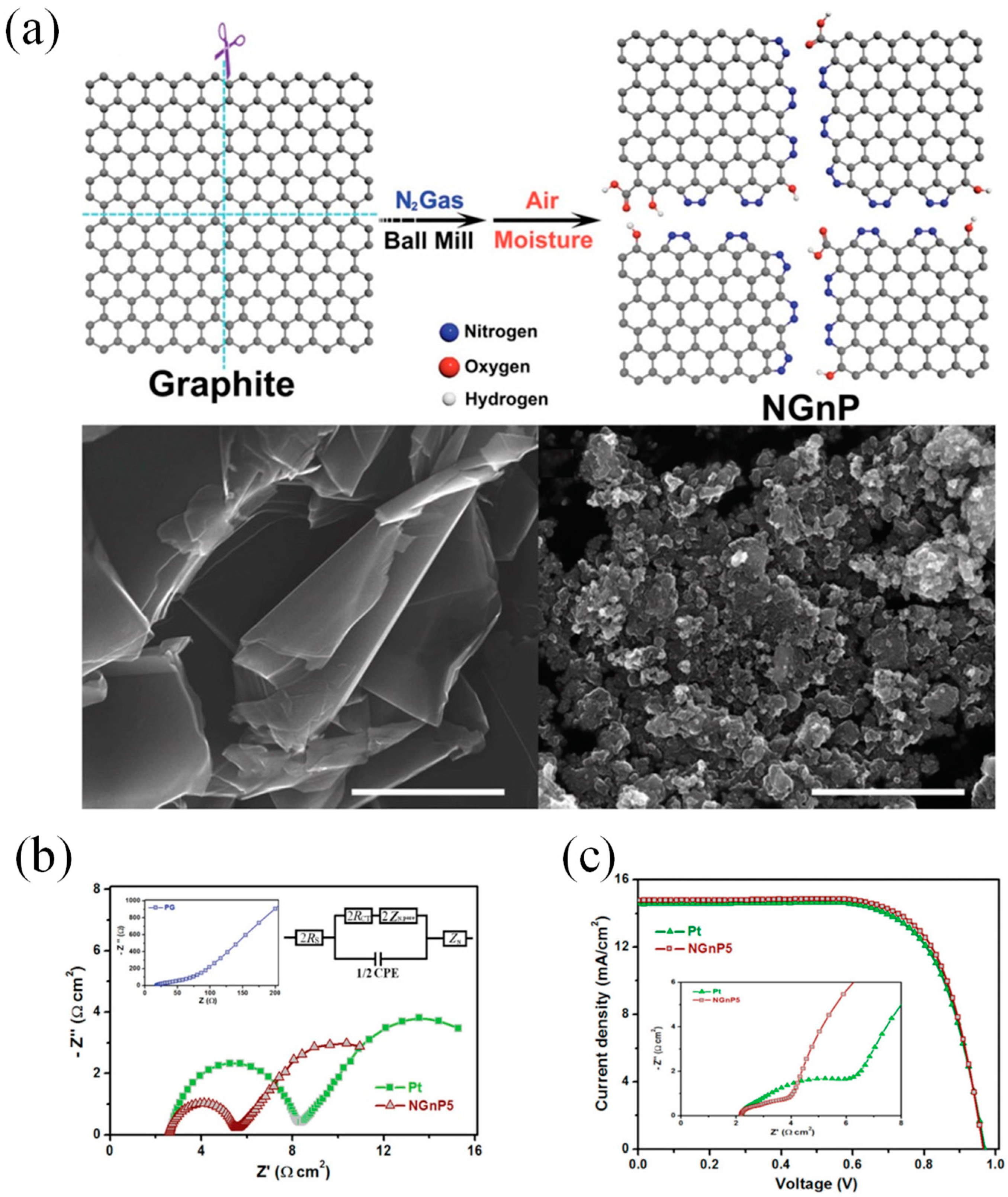
Many research groups have demonstrated that DSSCs with graphene CEs show the performances of DSSCs varied from 0.74% to 9.4% [37,38,39,40,41,42,43,44,45,46,47,48]. To the best of our knowledge, Xu and his coworkers were first to incorporate graphene materials as the catalytic CE for a DSSC [47]. The graphene sheets functionalized with 1-pyrenebutyrate (PB-G) were prepared by the reduction of graphene oxide. The conductivity of large-area flexible PB-G films exhibit seven orders of magnitude higher than that of the graphene oxide precursor. The efficiency of the DSSC with PB-G as a CE was measured to be 2.20%, compared to that of DSSC with standard Pt CE (3.98%). Graphene nanoplatelets (GnP) as a basic morphology of graphene have been prepared as the CE materials for DSSCs due to their large amount of active sites [49,50,51]. Ju et al. [14] prepared nitrogen-doped GNPs (NGnP) as metal-free electrocatalysts in DSSCs by ball-milling graphite in the presence of nitrogen gas (Figure 4a). The prepared NGnP show a structure of the nitrogen atom anchored at the edge of graphene nanoplatelets. The resultant NGnP CEs exhibited good electrocatalytic performance for the reduction of Co(bpy)33+, judging by the low charge-transfer resistance (Rct) values at the CE/electrolyte solution interface and high fill factor (71.9%) in DSSCs (Figure 4b). The performance of DSSCs with NGnP5 CE exhibited a PCE of up to 10.27%, which is higher than that of the DSSC with Pt-based CE (9.96%) (Figure 4c). Most importantly, the prepared NGnP CE exhibited superior stability compared to Pt CE by using the Co(bpy)32+/3+ redox couple. Where, the Co(bpy)32+/3+-based electrolytes not only provide higher voltage of DSSC, but also appear to be quite fast at carbon-based cathodes.
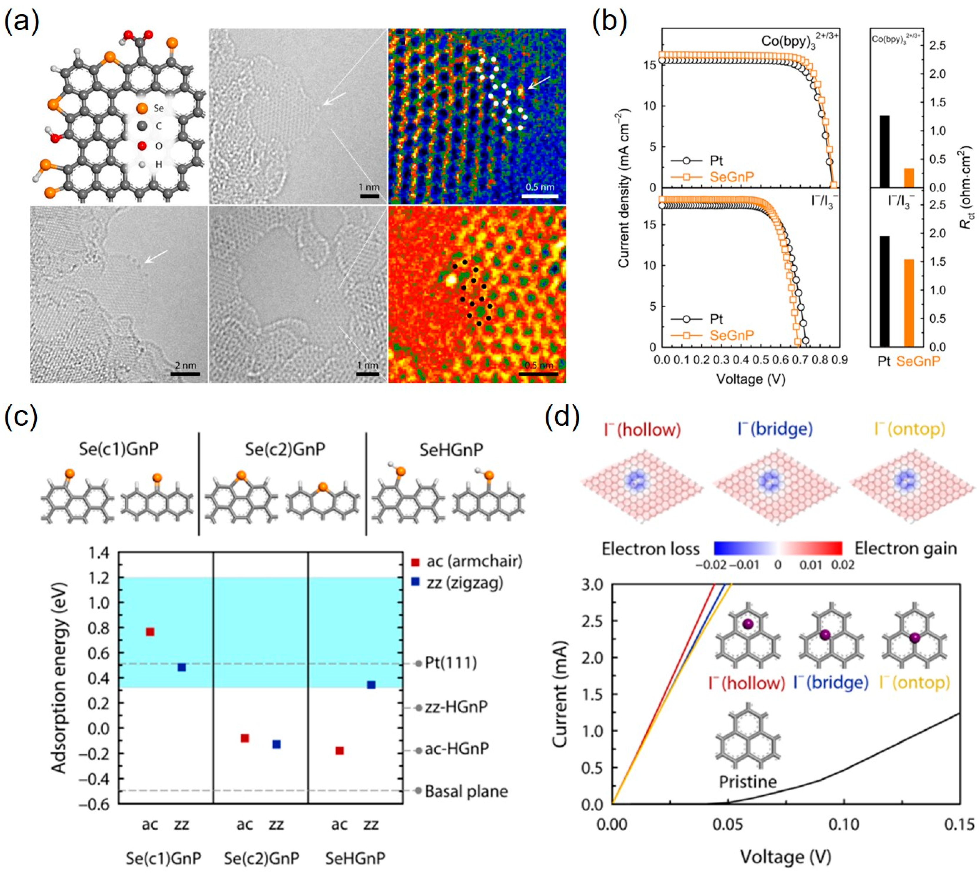
Additionally, Ju et al. [52] synthesized edge-selenated graphene nanoplatelets (SeGnPs) by a simple mechanochemical reaction between graphite and selenium (Se) powders. The SeGnPs preserved the completeness of graphene basal plane and selectively-doped selenium atom at the edge of graphene confirmed by atomic-resolution transmission electron microscopy (Figure 5a). The SeGnPs as a CE in DSSCs exhibit outstanding electrocatalytic performance and ultimately high stability in both Co(bpy)32+/3+ and conventional I−/I3− electrolyte solutions (Figure 5b). Furthermore, the theoretical calculations were applied to clarify the I3− reduction mechanism. They found that SeGnPs with single-coordinated armchair and zigzag edges demonstrated significantly enhanced electrocatalytic activity for I3− reduction (Figure 5c). The rapid electron transfer was made through the well-preserved graphitic basal plane to increase the current (Figure 5d). The efficiencies of SeGnP CE were respectively up to 10.98% and 9.17% in Co(bpy)32+/3+ and I−/I3− electrolyte solutions, compared to those of Pt CE 10.11% and 9.07% in Co(bpy)32+/3+ and I−/I3− electrolyte solutions, respectively.
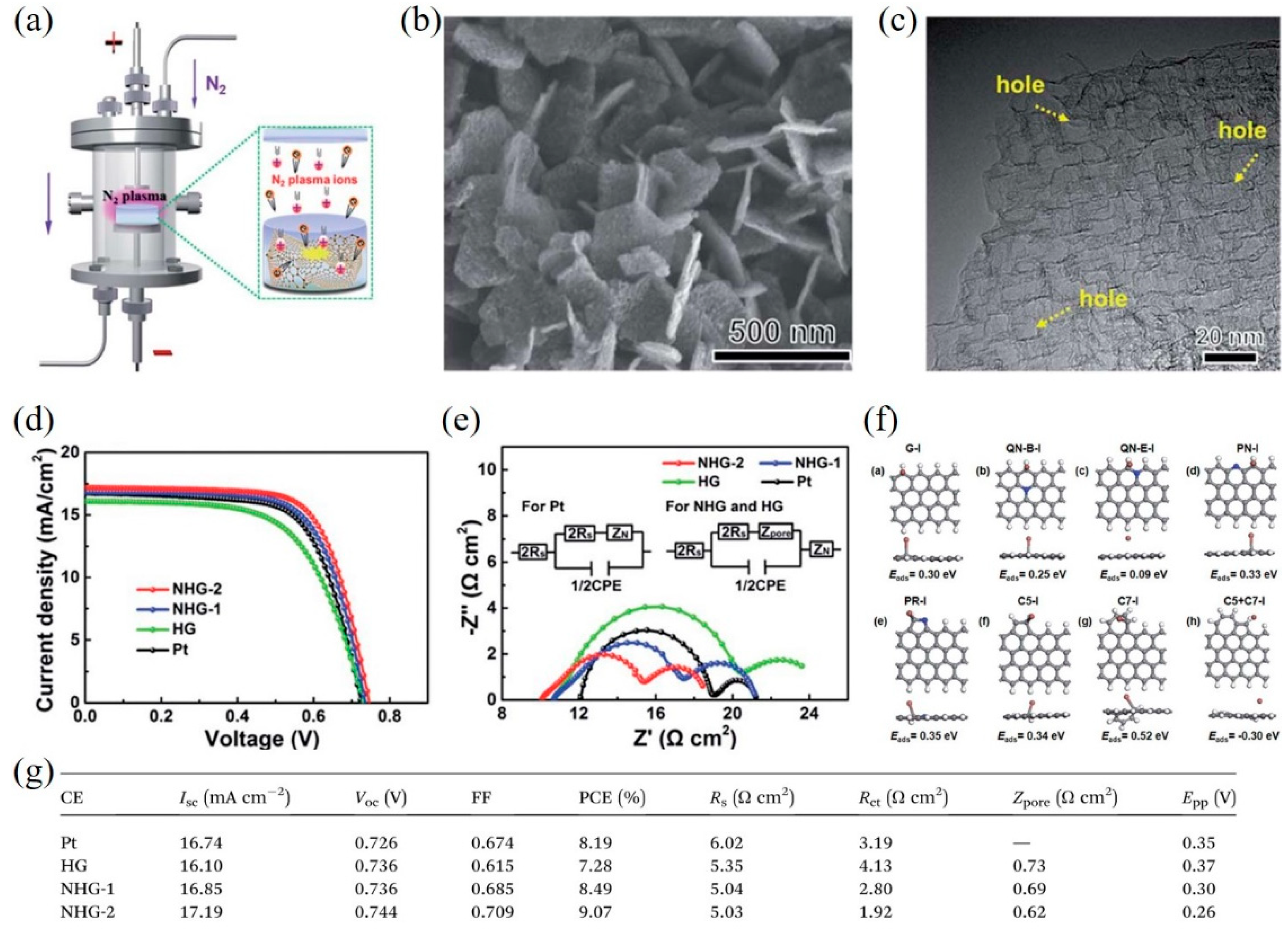
Structural engineering of graphene is an efficient route to increase the specific surface area and the number of active sites/defects. For example, Yang et al. [53] synthesized nitrogen-doped holey graphene (NHG) by chemical vapor deposition with MgO template and subsequently employing N2 plasma treatment (Figure 6a). High conductivity, large surface area and abundant edge-induced defects, and nitrogen dopants of NHG were obtained (Figure 6b,c), resulting in outstanding electrocatalytic activity for the I−/I3− redox reaction. The DSSCs with NHG CEs exhibited a higher PCE of 9.07% compared with that of DSSCs with Pt CEs (8.19%) (Figure 6d), which can be ascribed to the lower sheet resistance and Rct of NHG CEs (Figure 6e,g). Moreover, the detailed mechanism was further confirmed by density functional theory (DFT) calculations, which found that the pyridinic nitrogen (PN), pyrrolic nitrogen (PR), and edge-induced defects including five-carbon ring (C5) and seven-carbon ring (C7) act as catalytically active sites to greatly enhance the catalytic activity for the triiodide reduction reaction (Figure 6f).
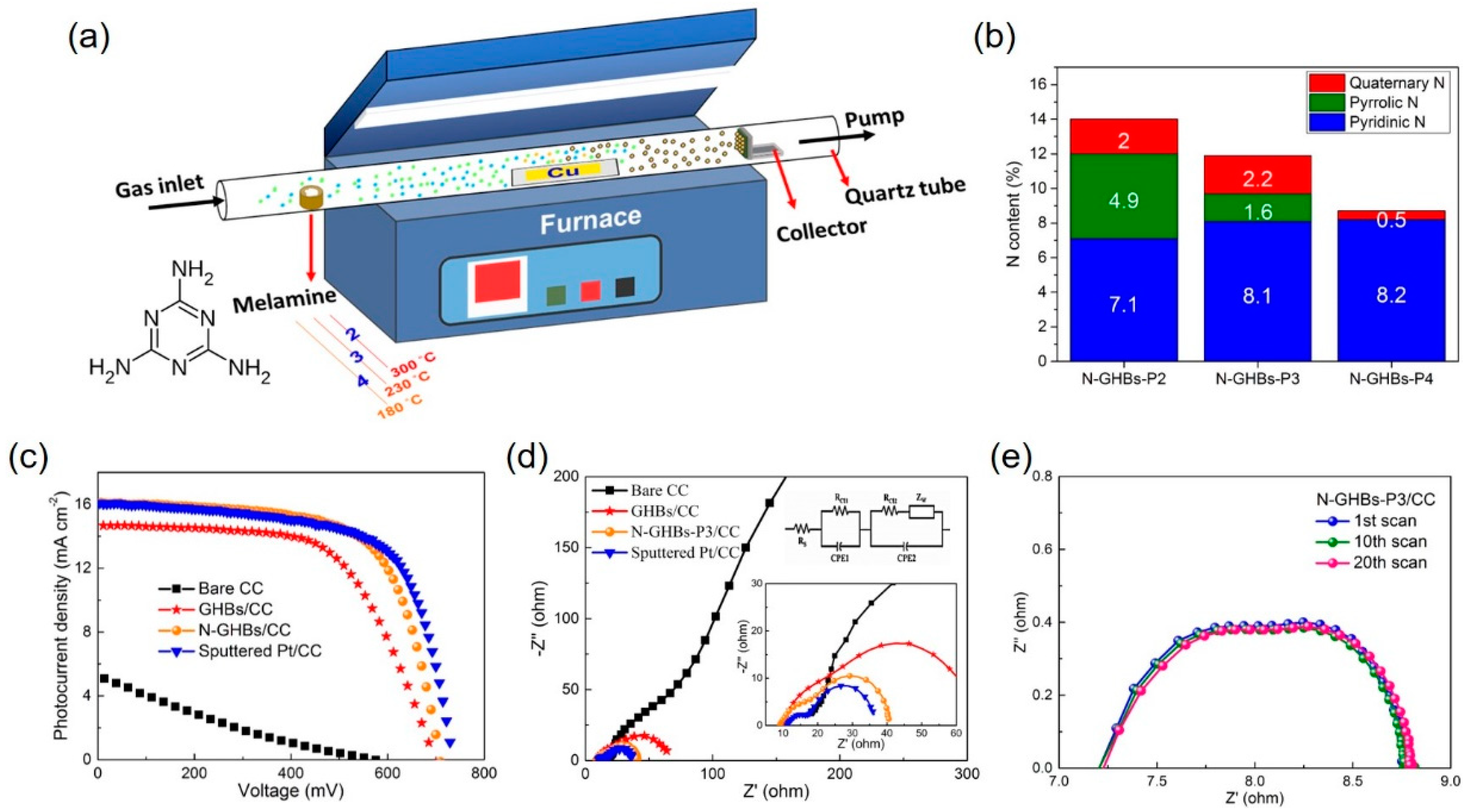
Tseng et al. [54] synthesized nitrogen-doped graphene hollow nanoballs (N-GHBs) by chemical vapor deposition (CVD) via an in situ nitrogen-doping approach (Figure 7a). N-GHBs were deposited directly on carbon cloth (CC) as an efficient metal-free electrocatalyst for DSSCs. The highly-curved N-GHBs largely improve the loss of specific surface area caused by the self-restacking of planar graphene sheets. Keeping oxygen contaminations from N-GHBs in in situ doping process, the characteristic electrical conductivity of graphene was preserved in the as-synthesized N-GHBs. The nitrogen-doping content of 8.7–14.0% and different nitrogen-doped configurations in N-GHBs could be controlled by changing the evaporation temperature of melamine as a nitrogen source (Figure 7b). By comparing the results of different nitrogen-doped states in N-GHBs and the corresponding DSSC performances, they found that the pyridinic and quaternary nitrogens, rather than the total nitrogen doping level, are mainly responsible for electrocatalytic activities toward triiodide reduction reaction. The nitrogen-doped high-surface-area GHBs remarkably improve the intrinsic electrocatalytic activity, lower the charge-transfer resistance (Figure 7d), and enhance the corresponding photovoltaic performance (7.53%), which is comparable to that (7.70%) of a standard sputtered Pt CE-based DSSC (Figure 7c and Table 1). The exceptional stability of N-GHBs was also demonstrated by EIS with several scan cycles (Figure 7e).
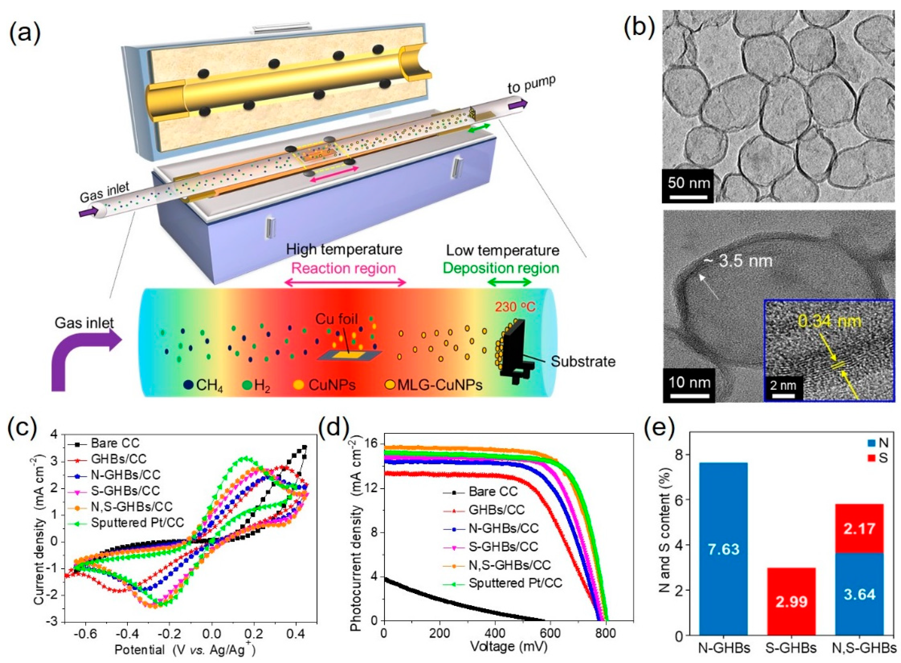
The electrocatalytic activity of graphene can be enhanced by introducing one kind of heteroatom as we reviewed above. To further increase the catalytic activity, dual-doped graphene was also achieved by theoretical calculation and experimental results [55,56,57,58]. Chang et al. [59] synthesized nitrogen and sulfur co-doped graphene hollow nanoballs (N,S-GHBs) via chemical vapor deposition (CVD) as a CE for DSSCs (Figure 8a). The transmission electron microscopic images revealed the hollow structure of GHBs and confirmed the interlayer spacing (0.34 nm) of graphene (Figure 8b). Nitrogen doping improves the adsorption of I3− due to the electron transfer caused by the electronegativity differences between carbon and nitrogen atoms. On the other hand, sulfur-doping approach generates the geometric distortion due to the larger size of sulfur than carbon, which activates the sp2 bonding structure of carbon into unsaturated sp3 bonding structure. Among these doped GHB samples, N,S-GHBs show the best catalytic performance due to the synergistic effect from both electronic and geometric changes, caused by the N- and S-doping, respectively (Figure 8e). The DSSC with a N,S-GHB CE exhibits the PCE of 9.02%, comparable to that (8.90%) of a Pt-based counterpart due to the decrease of Rct for triiodide reduction reaction (Figure 8c,d and Table 2).
4. Conclusions and Outlook
Dye-sensitized solar cells are becoming one of the representative third-generation solar cells because of their high solar-to-electric conversion efficiency, along with low cost, easy preparation, and environment benignity. The performance and the cost of DSSCs are highly dependent on the choice of counter electrodes. As a counter electrode, it must possess high electrocatalytic activity, high electrical conductivity, and excellent stability for electrolyte regeneration. Whereas, carbon materials have obvious advantages in price and abundance. However, the low intrinsic electrocatalytic activity is a limitation for achieving high-efficient counter electrodes. One or two kinds of heteroatom-doping in graphene have been demonstrated as an efficient route to improve the electrocatalytic activity. On the other hand, the structural transformation from two-dimensional graphene to three-dimensional graphene with meso-/micropores significantly enhanced the specific surface area and the diffusion of the electrolyte redox couples. Future development of carbon-based CEs should focus on the new designing ideas, e.g., the new methods and the new combination of carbon-based materials and other kinds of materials with high intrinsic electrocatalytic activity, aiming to achieve the conductivity, catalytic activity, and stability of CE materials; the defect site engineering on carbonaceous materials; the structural and interfacial engineering on carbonaceous materials. The active sites of CE materials for reduction of redox mediators in a DSSC have few understandings, which plays the crucial role on the improvement of the efficiency of a DSSC. Finally, it should be concerned with the interaction between each component in CE materials and/or CE materials and electrolyte solution.
Author Contributions
Conceptualization and organization, C.-P.L.; Writing—original draft, C.-A.T. All authors have read and agreed to the published version of the manuscript.
Funding
This research received funding from Ministry of Science and Technology (MOST) of Taiwan.
Acknowledgments
This work was supported by the Ministry of Science and Technology (MOST) of Taiwan, under grant numbers 107-2113-M-845-001-MY3.
Conflicts of Interest
The authors declare no conflict of interest.
References
- O’Regan, B.; Gratzel, M. The Study of Fast Processes and Transient Species by Electron Pulse Radiolysis. Nature 1991, 353, 737–740. [Google Scholar] [CrossRef]
- Kavan, L. Electrochemistry and Dye-Sensitized Solar Cells. Curr. Opin. Electrochem. 2017, 2, 88–96. [Google Scholar] [CrossRef]
- Hagfeldt, A.; Boschloo, G.; Sun, L.; Kloo, L.; Pettersson, H. Dye-Sensitized Solar Cells. Chem. Rev. 2010, 110, 6595–6663. [Google Scholar] [CrossRef]
- Sharma, K.; Sharma, V.; Sharma, S.S. Dye-Sensitized Solar Cells: Fundamentals and Current Status. Nanoscale Res. Lett. 2018, 13, 381. [Google Scholar] [CrossRef] [PubMed]
- Kavan, L.; Krysova, H.; Janda, P.; Tarabkova, H.; Saygili, Y.; Freitag, M.; Zakeeruddin, S.M.; Hagfeldt, A.; Grätzel, M. Novel Highly Active Pt/Graphene Catalyst for Cathodes of Cu(II/I)-Mediated Dye-Sensitized Solar Cells. Electrochim. Acta 2017, 251, 167–175. [Google Scholar] [CrossRef] [Green Version]
- Olsen, E.; Hagen, G.; Eric Lindquist, S. Dissolution of Platinum in Methoxy Propionitrile Containing LiI/I2. Sol. Energy Mater. Sol. Cells 2000, 63, 267–273. [Google Scholar] [CrossRef]
- Mohanty, S.P.; More, V.; Bhargava, P. Effect of Aging Conditions on the Performance of Dip Coated Platinum Counter Electrode Based Dye Sensitized Solar Cells. RSC Adv. 2015, 5, 18647–18654. [Google Scholar] [CrossRef]
- Yen, Y.S.; Chou, H.H.; Chen, Y.C.; Hsu, C.Y.; Lin, J.T. Recent Developments in Molecule-Based Organic Materials for Dye-Sensitized Solar Cells. J. Mater. Chem. 2012, 22, 8734–8747. [Google Scholar] [CrossRef]
- Wan, J.; Fang, G.; Yin, H.; Liu, X.; Liu, D.; Zhao, M.; Ke, W.; Tao, H.; Tang, Z. Pt-Ni Alloy Nanoparticles as Superior Counter Electrodes for Dye-Sensitized Solar Cells: Experimental and Theoretical Understanding. Adv. Mater. 2014, 26, 8101–8106. [Google Scholar] [CrossRef]
- Li, G.R.; Wang, F.; Jiang, Q.W.; Gao, X.P.; Shen, P.W. Carbon Nanotubes with Titanium Nitride as a Low-Cost Counterelectrode Material for Dye-Sensitized Solar Cells. Angew. Chem. Int. Ed. 2010, 49, 3653–3656. [Google Scholar] [CrossRef]
- Ju, M.J.; Jeon, I.Y.; Kim, J.C.; Lim, K.; Choi, H.J.; Jung, S.M.; Choi, I.T.; Eom, Y.K.; Kwon, Y.J.; Ko, J.; et al. Graphene Nanoplatelets Doped with N at Its Edges as Metal-Free Cathodes for Organic Dye-Sensitized Solar Cells. Adv. Mater. 2014, 26, 3055–3062. [Google Scholar] [CrossRef]
- Trevisan, R.; Döbbelin, M.; Boix, P.P.; Barea, E.M.; Tena-Zaera, R.; Mora-Seró, I.; Bisquert, J. PEDOT Nanotube Arrays as High Performing Counter Electrodes for Dye Sensitized Solar Cells. Study of the Interactions among Electrolytes and Counter Electrodes. Adv. Energy Mater. 2011, 1, 781–784. [Google Scholar] [CrossRef]
- Hou, W.; Xiao, Y.; Han, G.; Fu, D.; Wu, R. Serrated, Flexible and Ultrathin Polyaniline Nanoribbons: An Efficient Counter Electrode for the Dye-Sensitized Solar Cell. J. Power Sources 2016, 322, 155–162. [Google Scholar] [CrossRef]
- Wang, L.; Shi, Y.; Zhang, H.; Bai, X.; Wang, Y.; Ma, T. Iron Oxide Nanostructures as Highly Efficient Heterogeneous Catalysts for Mesoscopic Photovoltaics. J. Mater. Chem. A 2014, 2, 15279–15283. [Google Scholar] [CrossRef]
- Guo, J.; Shi, Y.; Zhu, C.; Wang, L.; Wang, N.; Ma, T. Cost-Effective and Morphology-Controllable Niobium Diselenides for Highly Efficient Counter Electrodes of Dye-Sensitized Solar Cells. J. Mater. Chem. A 2013, 1, 11874–11879. [Google Scholar] [CrossRef]
- Wu, M.; Lin, X.; Wang, Y.; Wang, L.; Guo, W.; Qi, D.; Peng, X.; Hagfeldt, A.; Grätzel, M.; Ma, T. Economical Pt-Free Catalysts for Counter Electrodes of Dye-Sensitized Solar Cells. J. Am. Chem. Soc. 2012, 134, 3419–3428. [Google Scholar] [CrossRef] [PubMed]
- Zhu, J.; Yang, D.; Yin, Z.; Yan, Q.; Zhang, H. Graphene and Graphene-Based Materials for Energy Storage Applications. Small 2014, 10, 3480–3498. [Google Scholar] [CrossRef]
- Roy-Mayhew, J.D.; Bozym, D.J.; Punckt, C.; Aksay, I.A. Functionalized Graphene as a Catalytic Counter Electrode in Dye-Sensitized Solar Cells. ACS Nano 2010, 4, 6203–6211. [Google Scholar] [CrossRef] [Green Version]
- Li, G.R.; Wang, F.; Song, J.; Xiong, F.Y.; Gao, X.P. TiN-Conductive Carbon Black Composite as Counter Electrode for Dye-Sensitized Solar Cells. Electrochim. Acta 2012, 65, 216–220. [Google Scholar] [CrossRef]
- He, B.; Meng, X.; Tang, Q.; Li, P.; Yuan, S.; Yang, P. Low-Cost CoPt Alloy Counter Electrodes for Efficient Dye-Sensitized Solar Cells. J. Power Sources 2014, 260, 180–185. [Google Scholar] [CrossRef]
- Wu, M.; Lin, X.; Wang, T.; Qiu, J.; Ma, T. Low-Cost Dye-Sensitized Solar Cell Based on Nine Kinds of Carbon Counter Electrodes. Energy Environ. Sci. 2011, 4, 2308–2315. [Google Scholar] [CrossRef]
- Roy-Mayhew, J.D.; Aksay, I.A. Graphene Materials and Their Use in Dye-Sensitized Solar Cells. Chem. Rev. 2014, 114, 6323–6348. [Google Scholar] [CrossRef] [PubMed]
- Kavan, L.; Yum, J.H.; Graetzel, M. Graphene-Based Cathodes for Liquid-Junction Dye Sensitized Solar Cells: Electrocatalytic and Mass Transport Effects. Electrochim. Acta 2014, 128, 349–359. [Google Scholar] [CrossRef]
- Li, G.R.; Gao, X.P. Low-Cost Counter-Electrode Materials for Dye-Sensitized and Perovskite Solar Cells. Adv. Mater. 2020, 32, 1–20. [Google Scholar] [CrossRef]
- Lim, S.P.; Pandikumar, A.; Lim, Y.S.; Huang, N.M.; Lim, H.N. In-Situ Electrochemically Deposited Polypyrrole Nanoparticles Incorporated Reduced Graphene Oxide as an Efficient Counter Electrode for Platinum-Free Dye-Sensitized Solar Cells. Sci. Rep. 2014, 4, 13–15. [Google Scholar] [CrossRef] [Green Version]
- Li, S.; Min, H.; Xu, F.; Tong, L.; Chen, J.; Zhu, C.; Sun, L. All Electrochemical Fabrication of MoS2/Graphene Counter Electrodes for Efficient Dye-Sensitized Solar Cells. RSC Adv. 2016, 6, 34546–34552. [Google Scholar] [CrossRef]
- Li, S.; Luo, Y.; Lv, W.; Yu, W.; Wu, S.; Hou, P.; Yang, Q.; Meng, Q.; Liu, C.; Cheng, H.M. Vertically Aligned Carbon Nanotubes Grown on Graphene Paper as Electrodes in Lithium-Ion Batteries and Dye-Sensitized Solar Cells. Adv. Energy Mater. 2011, 1, 486–490. [Google Scholar] [CrossRef]
- Choi, H.; Kim, H.; Hwang, S.; Choi, W.; Jeon, M. Dye-Sensitized Solar Cells Using Graphene-Based Carbon Nano Composite as Counter Electrode. Sol. Energy Mater. Sol. Cells 2011, 95, 323–325. [Google Scholar] [CrossRef]
- Sun, W.; Peng, T.; Liu, Y.; Huang, N.; Guo, S.; Zhao, X. Ordered Mesoporous Carbon-Decorated Reduced Graphene Oxide as Efficient Counter Electrode for Dye-Sensitized Solar Cells. Carbon N. Y. 2014, 77, 18–24. [Google Scholar] [CrossRef]
- Shao, L.L.; Chen, M.; Ren, T.Z.; Yuan, Z.Y. Ordered Mesoporous Carbon/Graphene Nano-Sheets Composites as Counter Electrodes in Dye-Sensitized Solar Cells. J. Power Sources 2015, 274, 791–798. [Google Scholar] [CrossRef]
- Kim, H.; Choi, H.; Hwang, S.; Kim, Y.; Jeon, M. Fabrication and Characterization of Carbon-Based Counter Electrodes Prepared by Electrophoretic Deposition for Dye-Sensitized Solar Cells. Nanoscale Res. Lett. 2012, 7, 2–5. [Google Scholar] [CrossRef] [PubMed] [Green Version]
- Zhu, G.; Pan, L.; Lu, T.; Xu, T.; Sun, Z. Electrophoretic Deposition of Reduced Graphene-Carbon Nanotubes Composite Films as Counter Electrodes of Dye-Sensitized Solar Cells. J. Mater. Chem. 2011, 21, 14869–14875. [Google Scholar] [CrossRef]
- Yu, K.; Wang, P.; Lu, G.; Chen, K.H.; Bo, Z.; Chen, J. Patterning Vertically Oriented Graphene Sheets for Nanodevice Applications. J. Phys. Chem. Lett. 2011, 2, 537–542. [Google Scholar] [CrossRef]
- Yang, K.; Wang, J.; Chen, B. Facile Fabrication of Stable Monolayer and Few-Layer Graphene Nanosheets as Superior Sorbents for Persistent Aromatic Pollutant Management in Water. J. Mater. Chem. A 2014, 2, 18219–18224. [Google Scholar] [CrossRef]
- Pham, H.D.; Pham, V.H.; Cuong, T.V.; Nguyen-Phan, T.D.; Chung, J.S.; Shin, E.W.; Kim, S. Synthesis of the Chemically Converted Graphene Xerogel with Superior Electrical Conductivity. Chem. Commun. 2011, 47, 9672–9674. [Google Scholar] [CrossRef]
- Xue, Y.; Ding, Y.; Niu, J.; Xia, Z.; Roy, A.; Chen, H.; Qu, J.; Wang, Z.L.; Dai, L. Rationally Designed Graphene-Nanotube 3D Architectures with a Seamless Nodal Junction for Efficient Energy Conversion and Storage. Sci. Adv. 2015, 1, e1400198. [Google Scholar] [CrossRef] [Green Version]
- Das, S.; Sudhagar, P.; Verma, V.; Song, D.; Ito, E.; Lee, S.Y.; Kang, Y.S.; Choi, W. Amplifying Charge-Transfer Characteristics of Graphene for Triiodide Reduction in Dye-Sensitized Solar Cells. Adv. Funct. Mater. 2011, 21, 3729–3736. [Google Scholar] [CrossRef]
- Zhang, D.W.; Li, X.D.; Li, H.B.; Chen, S.; Sun, Z.; Yin, X.J.; Huang, S.M. Graphene-Based Counter Electrode for Dye-Sensitized Solar Cells. Carbon N. Y. 2011, 49, 5382–5388. [Google Scholar] [CrossRef]
- Roy-Mayhew, J.D.; Boschloo, G.; Hagfeldt, A.; Aksay, I.A. Functionalized Graphene Sheets as a Versatile Replacement for Platinum in Dye-Sensitized Solar Cells. ACS Appl. Mater. Interfaces 2012, 4, 2794–2800. [Google Scholar] [CrossRef]
- Luo, Q.; Hao, F.; Wang, S.; Shen, H.; Zhao, L.; Li, J.; Grätzel, M.; Lin, H. Highly Efficient Metal-Free Sulfur-Doped and Nitrogen and Sulfur Dual-Doped Reduced Graphene Oxide Counter Electrodes for Dye-Sensitized Solar Cells. J. Phys. Chem. C 2014, 118, 17010–17018. [Google Scholar] [CrossRef]
- Kavan, L.; Yum, J.H.; Nazeeruddin, M.K.; Grätzel, M. Graphene Nanoplatelet Cathode for Co(III)/(II) Mediated Dye-Sensitized Solar Cells. ACS Nano 2011, 5, 9171–9178. [Google Scholar] [CrossRef] [PubMed]
- Kavan, L.; Yum, J.H.; Grätzel, M. Graphene Nanoplatelets Outperforming Platinum as the Electrocatalyst in Co-Bipyridine-Mediated Dye-Sensitized Solar Cells. Nano Lett. 2011, 11, 5501–5506. [Google Scholar] [CrossRef] [PubMed]
- Kavan, L.; Yum, J.H.; Grätzel, M. Optically Transparent Cathode for Dye-Sensitized Solar Cells Based on Graphene Nanoplatelets. ACS Nano 2011, 5, 165–172. [Google Scholar] [CrossRef] [PubMed]
- Lee, J.S.; Ahn, H.J.; Yoon, J.C.; Jang, J.H. Three-Dimensional Nano-Foam of Few-Layer Graphene Grown by CVD for DSSC. Phys. Chem. Chem. Phys. 2012, 14, 7938–7943. [Google Scholar] [CrossRef] [PubMed] [Green Version]
- Xu, Y.; Bai, H.; Lu, G.; Li, C.; Shi, G. Flexible Graphene Films via the Filtration of Water-Soluble Noncovalent Functionalized Graphene Sheets. J. Am. Chem. Soc. 2008, 130, 5856–5857. [Google Scholar] [CrossRef]
- Dou, Y.Y.; Li, G.R.; Song, J.; Gao, X.P. Nickel Phosphide-Embedded Graphene as Counter Electrode for Dye-Sensitized Solar Cells. Phys. Chem. Chem. Phys. 2012, 14, 1339–1342. [Google Scholar] [CrossRef]
- Cruz, R.; Pacheco Tanaka, D.A.; Mendes, A. Reduced Graphene Oxide Films as Transparent Counter-Electrodes for Dye-Sensitized Solar Cells. Sol. Energy 2012, 86, 716–724. [Google Scholar] [CrossRef]
- Hsieh, C.T.; Yang, B.H.; Lin, J.Y. One- and Two-Dimensional Carbon Nanomaterials as Counter Electrodes for Dye-Sensitized Solar Cells. Carbon N. Y. 2011, 49, 3092–3097. [Google Scholar] [CrossRef]
- Gong, J.; Zhou, Z.; Sumathy, K.; Yang, H.; Qiao, Q. Activated Graphene Nanoplatelets as a Counter Electrode for Dye-Sensitized Solar Cells. J. Appl. Phys. 2016, 119, 135501. [Google Scholar] [CrossRef]
- Ju, M.J.; Jeon, I.Y.; Lim, K.; Kim, J.C.; Choi, H.J.; Choi, I.T.; Eom, Y.K.; Kwon, Y.J.; Ko, J.; Lee, J.J.; et al. Edge-Carboxylated Graphene Nanoplatelets as Oxygen-Rich Metal-Free Cathodes for Organic Dye-Sensitized Solar Cells. Energy Environ. Sci. 2014, 7, 1044–1052. [Google Scholar] [CrossRef] [Green Version]
- Kim, H.M.; Jeon, I.Y.; Choi, I.T.; Kang, S.H.; Shin, S.H.; Jeong, H.Y.; Ju, M.J.; Baek, J.B.; Kim, H.K. Edge-Selectively Antimony-Doped Graphene Nanoplatelets as an Outstanding Counter Electrode with an Unusual Electrochemical Stability for Dye-Sensitized Solar Cells Employing Cobalt Electrolytes. J. Mater. Chem. A 2016, 4, 9029–9037. [Google Scholar] [CrossRef]
- Ju, M.J.; Jeon, I.Y.; Kim, H.M.; Choi, J., II; Jung, S.M.; Seo, J.M.; Choi, I.T.; Kang, S.H.; Kim, H.S.; Noh, M.J.; et al. Edge-Selenated Graphene Nanoplatelets as Durable Metal-Free Catalysts for Iodine Reduction Reaction in Dye-Sensitized Solar Cells. Sci. Adv. 2016, 2, e1501459. [Google Scholar] [CrossRef] [PubMed] [Green Version]
- Yang, W.; Xu, X.; Hou, L.; Ma, X.; Yang, F.; Wang, Y.; Li, Y. Insight into the Topological Defects and Dopants in Metal-Free Holey Graphene for Triiodide Reduction in Dye-Sensitized Solar Cells. J. Mater. Chem. A 2017, 5, 5952–5960. [Google Scholar] [CrossRef]
- Tseng, C.-A.; Lee, C.-P.; Huang, Y.-J.; Pang, H.-W.; Ho, K.-C.; Chen, Y.-T. One-Step Synthesis of Graphene Hollow Nanoballs with Various Nitrogen-Doped States for Electrocatalysis in Dye-Sensitized Solar Cells. Mater. Today Energy 2018, 8, 15–21. [Google Scholar] [CrossRef]
- Yu, C.; Liu, Z.; Meng, X.; Lu, B.; Cui, D.; Qiu, J. Nitrogen and Phosphorus Dual-Doped Graphene as a Metal-Free High-Efficiency Electrocatalyst for Triiodide Reduction. Nanoscale 2016, 8, 17458–17464. [Google Scholar] [CrossRef]
- Liang, J.; Jiao, Y.; Jaroniec, M.; Qiao, S.Z. Sulfur and Nitrogen Dual-Doped Mesoporous Graphene Electrocatalyst for Oxygen Reduction with Synergistically Enhanced Performance. Angew. Chem. Int. Ed. Engl. 2012, 51, 11496–11500. [Google Scholar] [CrossRef]
- Chen, J.F.; Mao, Y.; Wang, H.F.; Hu, P. Theoretical Study of Heteroatom Doping in Tuning the Catalytic Activity of Graphene for Triiodide Reduction. ACS Catal. 2016, 6, 6804–6813. [Google Scholar] [CrossRef] [Green Version]
- Kannan, A.G.; Zhao, J.; Jo, S.G.; Kang, Y.S.; Kim, D.W. Nitrogen and Sulfur Co-Doped Graphene Counter Electrodes with Synergistically Enhanced Performance for Dye-Sensitized Solar Cells. J. Mater. Chem. A 2014, 2, 12232–12239. [Google Scholar] [CrossRef]
- Chang, Y.C.; Tseng, C.A.; Lee, C.P.; Ann, S.B.; Huang, Y.J.; Ho, K.C.; Chen, Y.T. N-and S-Codoped Graphene Hollow Nanoballs as an Efficient Pt-Free Electrocatalyst for Dye-Sensitized Solar Cells. J. Power Sources 2020, 449, 227470. [Google Scholar] [CrossRef]
Figure 1.
(a) A schematic representation of a dye-sensitized solar cell (DSSC). (b) Energy diagram and desired electron pathway for a DSSC. CB and VB refer to the conduction band and valence band, respectively. EF represents the Fermi level of the semiconductor. LUMO and HOMO levels are the lowest unoccupied and highest unoccupied molecular orbitals of the sensitizer. Reprinted with permission from [5]. Copyright (2014) American Chemical Society. (c) A schematic illustration of the impedance in a DSSC and equivalent circuit and (d) the corresponding Nyquist plot. Rr represents the charge-transfer resistance at the oxide/electrolyte interface. Cdl and Cµ represent the double-layer capacitance and nanocrystalline oxide capacitance, respectively [10,11]. Copyright 2020, WILEY-VCH.

Figure 2.
The plot of exchange current density (j0) of different counter electrodes (CEs) with their theoretical conductivity [11]. Copyright 2020, WILEY-VCH.
Figure 2.
The plot of exchange current density (j0) of different counter electrodes (CEs) with their theoretical conductivity [11]. Copyright 2020, WILEY-VCH.

Figure 3.
(a) Schematic of the all electrochemical fabrication approach. Reproduced from [26] with permission from the Royal Society of Chemistry. (b) Schematic diagram of device process including synthesis of GMWNTs on SiO2/Si, lift-off process of GMWNTs, transferring to FTO glass and half-cell fabrication [28]. Copyright 2011, Elsevier.

Figure 4.
(a) A schematic illustration and SEM images of producing NGnP by the ball-milling graphite in the presence of nitrogen and subsequently exposing it to moisture in the air. (b) (top) Nyquist plot of electrochemical impedance spectrum (EIS) obtained from symmetrical dummy cells with the Pt/FTO and NGnP5/FTO electrodes. (bottom) Current–voltage characteristics of the DSSCs with the Pt and the NGnP5 CEs under AM1.5 illumination. (c) A table lists the photovoltaic parameters of the DSSCs with Pt and NGnP CEs [14]. Copyright 2014, WILEY-VCH.

Figure 5.
(a) A schematic illustration, atomic-resolution transmission electron microscopy, and corresponding inverse fast Fourier transform images of SeGnPs. (b) Current-voltage characteristics and Rct of DSSCs with Pt and SeGnP CEs. (c) (top) Representative illustrations of single-coordinated (Se(c1)), double-coordinated (Se(c2)), and hydrogenated Se (SeH)-doped armchair (ac) and zigzag (zz) graphene edges. (bottom) The adsorption energies of the I atom were evaluated and compared with the undoped edge and basal plane cases. The shaded region indicates the iodine reduction reaction activity criterion. (d) (top) For various I− and I3−-adsorbed graphene basal plane models. (bottom) The current-voltage curves were calculated and compared with those from pristine grapheme [52].

Figure 6.
(a) A schematic presentation of nitrogen-doped holey graphene (NHG) synthesis by N2 plasma treatment. A SEM image (b) and a high-resolution TEM image (c) of NHG. (d) Current-voltage characteristics of the DSSCs with different CEs. (e) EIS measurement and the corresponding equivalent circuits (inset). (f) The adsorption energy of I atom for various types of graphene structures. The gray, blue, brown, and white balls stand for carbon, nitrogen, iodine, and hydrogen atoms, respectively. (g) Photovoltaic parameters of DSSCs with different CEs and the resulting data from cyclic voltammetry and EIS. Reproduced from [53] with permission from the Royal Society of Chemistry.

Figure 7.
(a) A schematic representation of the chemical vapor deposition (CVD) design for N-GHBs synthesis. (b) Distributions of various N-doped configurations with different N-GHBs samples. (c) Photocurrent density-voltage curves. (d) EIS of various CEs-based DSSCs were investigated. (e) EIS stability test of the symmetrical dummy cells with two identical electrodes of N-GHBs-P3/CC [54]. Copyright 2018, Elsevier.

Figure 8.
(a) A schematic illustration represents the growth of graphene hollow nanoballs (GHBs) on carbon cloth (CC) in a CVD reaction. (b) HR-TEM reveals the hollow structure and the lattice spacing of 0.34 nm of GHBs. (c) Cyclic voltammograms were tested with various CEs. (d) Photocurrent density vs. voltage curves of DSSCs with different CEs. (e) The doping amounts of the N and S atoms in N-GHBs/CC, S-GHBs/CC, and N,S-GHBs/CC are displayed for comparison [59]. Copyright 2020, Elsevier.


Table 1.
The parameters of the DSSCs with various counter electrodes were measured under AM 1.5G illumination [54].
Table 1.
The parameters of the DSSCs with various counter electrodes were measured under AM 1.5G illumination [54].
| Counter Electrodes | η (%) | VOC (mV) | JSC (mA cm−2) | FF | JIPCE (mA cm−2) |
|---|---|---|---|---|---|
| Bare CC | 0.48 ± 0.11 | 571 ± 2 | 4.33 ± 0.83 | 0.19 ± 0.01 | 4.14 |
| GHBs/CC | 6.20 ± 0.06 | 697 ± 5 | 14.50 ± 0.27 | 0.61 ± 0.01 | 14.29 |
| N-GHBs-P3/CC | 7.53 ± 0.06 | 703 ± 5 | 16.09 ± 0.18 | 0.67 ± 0.01 | 15.99 |
| Sputtered Pt/CC | 7.70 ± 0.14 | 735 ± 13 | 15.87 ± 0.32 | 0.66 ± 0.01 | 15.77 |
Table 2.
The photovoltaic parameters of various CEs in a DSSC are compared under AM 1.5 G (100 mW cm−2) illumination [59].
Table 2.
The photovoltaic parameters of various CEs in a DSSC are compared under AM 1.5 G (100 mW cm−2) illumination [59].
| Counter Electrodes | η (%) | VOC (mV) | JSC (mA cm−2) | FF | JIPCE (mA cm−2) |
|---|---|---|---|---|---|
| Bare CC | 0.41 | 570 | 3.80 | 0.19 | 3.67 |
| GHBs/CC | 6.47 | 785 | 13.33 | 0.62 | 13.06 |
| N-GHBs/CC | 7.48 | 776 | 14.44 | 0.67 | 14.07 |
| S-GHBs/CC | 8.15 | 785 | 14.84 | 0.70 | 14.68 |
| N,S-GHBs/CC | 9.02 | 798 | 15.71 | 0.72 | 15.56 |
| Sputtered Pt/CC | 8.90 | 802 | 15.22 | 0.73 | 14.96 |
© 2020 by the authors. Licensee MDPI, Basel, Switzerland. This article is an open access article distributed under the terms and conditions of the Creative Commons Attribution (CC BY) license (http://creativecommons.org/licenses/by/4.0/).
Share and Cite
MDPI and ACS Style
Tseng, C.-A.; Lee, C.-P. Highly Active Carbon-Based Electrocatalysts for Dye-Sensitized Solar Cells: A Brief Review. Physics 2020, 2, 412-424. https://0-doi-org.brum.beds.ac.uk/10.3390/physics2030023
AMA Style
Tseng C-A, Lee C-P. Highly Active Carbon-Based Electrocatalysts for Dye-Sensitized Solar Cells: A Brief Review. Physics. 2020; 2(3):412-424. https://0-doi-org.brum.beds.ac.uk/10.3390/physics2030023
Chicago/Turabian StyleTseng, Chi-Ang, and Chuan-Pei Lee. 2020. "Highly Active Carbon-Based Electrocatalysts for Dye-Sensitized Solar Cells: A Brief Review" Physics 2, no. 3: 412-424. https://0-doi-org.brum.beds.ac.uk/10.3390/physics2030023