Enhanced Chiral Mie Scattering by a Dielectric Sphere within a Superchiral Light Field


School of Optical-Electrical and Computer Engineering, University of Shanghai for Science and Technology, Shanghai 200093, China
*
Author to whom correspondence should be addressed.
Physics 2021, 3(3), 747-756; https://0-doi-org.brum.beds.ac.uk/10.3390/physics3030046
Submission received: 30 June 2021
/
Revised: 21 August 2021
/
Accepted: 23 August 2021
/
Published: 2 September 2021
(This article belongs to the Special Issue Dedication to Professor Michael Tribelsky: 50 Years in Physics)
Abstract
:A superchiral field, which can generate a larger chiral signal than circularly polarized light, is a promising mechanism to improve the capability to characterize chiral objects. In this paper, Mie scattering by a chiral sphere is analyzed based on the T-matrix method. The chiral signal by circularly polarized light can be obviously enhanced due to the Mie resonances. By employing superchiral light illumination, the chiral signal is further enhanced by 46.8% at the resonance frequency. The distribution of the light field inside the sphere is calculated to explain the enhancement mechanism. The study shows that a dielectric sphere can be used as an excellent platform to study the chiroptical effects at the nanoscale.
1. Introduction
Chirality describes the asymmetric feature of a three-dimensional object, whose mirror image is different from itself [1]. Objects with chirality are quite common in nature. In the human body, most of the important molecules have chirality, such as DNA, enzyme, and protein. As a wave phenomenon, the light field also has chirality [2]. A well-known example is circularly polarized light (CPL). Left circularly polarized (LCP) and right circularly polarized (RCP) light beams are a pair of enantiomers that have opposite spins. The interaction between the light field and chiral objects has attracted great interest from researchers [3]. The chiral properties of the objects can be evaluated by the different responses under illumination of LCP and RCP lights. This chiral signal is useful to distinguish and measure the chirality of a sample. In natural materials, the chiral signal is very weak (–) [1]. The main reason is the mismatch between the size of the chiral molecules and the light wavelength. In previous studies, it has been shown that plasmonic structures can increase chiral signals by orders of magnitude owing to the strong light confinement near the metallic surface [4]. The plasmonic chiral structure is used to improve the sensing performance of enantiomers [5]. In a nonchiral structure, optical chirality can be largely increased [6]. It has been shown that the local chirality of the light field can be tailored near the plasmonic structure. The optical antenna theory can be used to design the chiral light [7]. Symmetric metal–dielectric–metal (MDM) metamaterial structures have also been proposed to enhance the chiral light–matter interaction [8]. However, metals have intrinsic loss, which fundamentally limits the practical performance of the designed plasmonic structures. Recently, dielectric nanoparticles with high refractive indices have also been used to manipulate the light field at the nanoscale [9]. The supercavity with high q-factor can be designed by subwavelength high-index particles [10]. The electric and magnetic resonances in silicon nanoparticles can be utilized to enhance the quantum efficiency of silicon nanoparticles [11]. The anapole mode in such kind of particles has been intensively studied recently [12]. The simplest case of an anapole is caused by the destructive interference between the electric dipole and the toroidal moment. In 2015, the radiationless anapole mode in visible was first observed [13]. By tuning the geometry of the scattering particle, an obvious dip can be found in the far-field scattering spectrum, which is caused by the excitation of the anapole mode. Moreover, by tailoring the incident field, the anapole mode can also be excited in a dielectric sphere [14]. The electric and magnetic resonances can be strongly excited inside the high-index particles with low loss, which may further enable the chirality enhancement. Besides the enhancement mechanism arising from near-field structures, the enhancement of a chiral signal can also be realized by tailoring the light field. Traditionally, circularly polarized light is believed to have the highest chirality. However, Cohen proposed the superchiral field, which has larger chirality than circular polarized light [15,16]. Recently, it was demonstrated by us that a localized superchiral hotspot can be generated by tightly focusing a vectorial light beam with orbital angular momentum [17].
In this study, a method based on the T-matrix is employed to efficiently analyze the scattering process by a chiral sphere. It is demonstrated that two enhancement mechanisms can be employed to enhance the scattering circular dichroism (CD) signal of a chiral sphere simultaneously.
2. Materials and Methods
To consider the chiral property of the sphere in our theoretical model, the following constitutive relations are used [18]:
In Equations (1) and (2), , , and are the permittivity, permeability, and chirality parameters of the material in the sphere. Following the procedure proposed by Bohren [19], the electromagnetic field in the chiral sphere (, ) can be expressed by the linear transformation relation:
Because of the transformed fields, and should satisfy the wave equation, . They can be expanded by the linear combination of vector spherical harmonics (VSHs):
where , and m and n are both integers. In this study, and are regular VSHs whose values at origin are finite, and and are outgoing VSHs with singularity points at origin. The definitions of these VSH functions can be found in [20]. Outside the sphere, the incident field (, and scattering field (, ) can be expressed as the combinations of VSHs:
In Equations (6) and (7), the expansion coefficients and can be determined by the incident light field. The multipolar decomposition of various types of focused beams was considered in previous studies [21]. The expansion coefficients of and for the scattering field can be calculated by the T-matrix method. According to the boundary condition on the surface of the sphere (r = ), the T-matrix for a chiral sphere can be obtained from:
In Equation (10), the elements of the matrices and are given below:
In Equations (11)–(18), the Riccati–Bessel functions are defined as and . Z0 is the vacuum impedance. k0 = ω/c is the wave vector in vacuum. According to the Mie theory, the scattering power can be calculated by:
The radius of the sphere is = 75 nm, and the parameters of the chiral material are = 25, = 1, and = 0.01. The scattering spectrum under the illumination of linearly polarized light in free space ( = 1) is shown in Figure 1a. In the frequency range of 200–700 THz, the scattering power is mainly caused by terms related to an electric dipole (ED), magnetic dipole (MD), and magnetic quadrupole (MQ) [22]. Their contributions to the scattering power can be analyzed by the following three terms from the total scattering power:
In Figure 1b, the spectral curves for the three scattering terms are helpful to analyze the mechanisms of the Mie resonances. It can be clearly demonstrated that the three peaks of in Figure 1a are caused by the MD, ED, and MQ resonances at frequencies of 388.5, 538.5, and 563.5 THz, respectively. Linearly polarized light can be represented as the superposition of left- and right-hand circularly polarized light. The circularly polarized light is useful to explore the properties of materials [23]. To evaluate the chiral response of the sphere, the scattering CD parameter is calculated, which is defined as . In this definition, and are the scattering energies by the chiral sphere under the illuminations of LCP and RCP light. There are two regions in the spectrum in Figure 1c, where the scattering CD single is enhanced. One region is near the MD resonance wavelength, and the other is near the ED resonance wavelength. However, the signs of CD values in the two ranges are opposite. The inversion of the optical chiral response can be attributed to the main absorption mechanism, which is converted from MD to ED when the light frequency is increased. In the region where ED absorption is dominant, there exists a deep valley at a frequency of 563.5 THz, which is exactly the MQ resonance frequency.
As discussed above, the light field can be tailored to gain larger chirality than CPL. To evaluate the chirality of the light field, the parameter of the CD enhancement factor is defined as g/, where g and are the CD values of a chiral dipole excited by the tailored light and CPL light. When g/ > 1, the tailored light can produce a larger CD signal than CPL light. This kind of light is called superchiral field. Recently, it was reported by us a highly localized superchiral hotspot by tightly focusing a radially polarized beam with orbital angular momentum near the dielectric interface [17]. In this study, the capability of the superchiral field to increase the scattering CD signal can be verified, when the particle is at the Mie resonance. It has been proved that when the incident angle of a focused beam is slightly smaller than the critical angle of totally internal reflection, the chirality of the light field (g/) can be largely enhanced. Therefore, the configuration in Figure 2 is considered. The chiral sphere is on the substrate with a refractive index of , which is larger than . To analyze the interaction between the chiral sphere on the substrate and the superchiral field, the T-matrix in Equation (10) should be modified to incorporate the substrate into the theoretical model [22,24]. The scattering process is illustrated in Figure 2. The light propagates from the substrate () to the air (), and the chiral sphere is illuminated by the transmitted light (, ). The scattering field is expressed as [, ]T = T[, ]T, where the T-matrix is given in Equations (11)–(18). As shown by the red arrow in Figure 2, a part of the scattering field can be reflected by the interface, and then the reflected field can also be scattered by the sphere again. One can see that there is a round trip of light between the sphere and the interface. Therefore, the multiple reflections between the sphere and the interface should be considered to build the accurate scattering model. In this study, the matrix of is the reflection matrix, and the reflected field of the scattering field can be expressed as [, ]T. The final scattering field of the multiscattering process can be calculated by Equation (23) [24].
According to Equation (23), the T-matrix for the sphere in free space should be modified as the effective one, which is Teff = [I − T]−1T. I represents the unit matrix. The elements of are the reflection coefficients of VSHs by the interface. To calculate these coefficients, the VSH is first expanded by the plane waves. The directions of the plane waves are represented by , where is the polar angle and is the azimuthal angle. The reflection coefficient of each plane wave can be calculated independently by the Fresnel equation. The reflected field of the VSH can be obtained by recombining all the reflected plane wave components. After these operations, the reflected field of each VSH field scattered by the sphere can be calculated. To calculate the elements of LR, the reflected fields have to be expended by the VSH basis, which has been used to express the incident field of [, ]T in Equations (6) and (7). The expansions of the reflected VSHs, and can be expressed as:
In Equations (24) and (25), the expansion coefficients can be determined by the following integrals with the integration path of being :
In Equations (26)–(29), and are the Fresnel reflection coefficients for p-polarized and s-polarized light, and are the angle-dependent functions in the Mie theory for convenience [20]. The expression of is in Equations (26)–(29), which is only related to the order numbers (n, m and ν):
After obtaining the coefficients in Equations (26)–(29), the reflected matrix can be expressed as:
Based on the theoretical model, light scattering by the sphere in the superchiral field can be analyzed efficiently. To further simplify the calculation, let us consider the vectorial Bessel beam as the incident light, whose field in a cylindrical coordinate can be expressed as [25]:
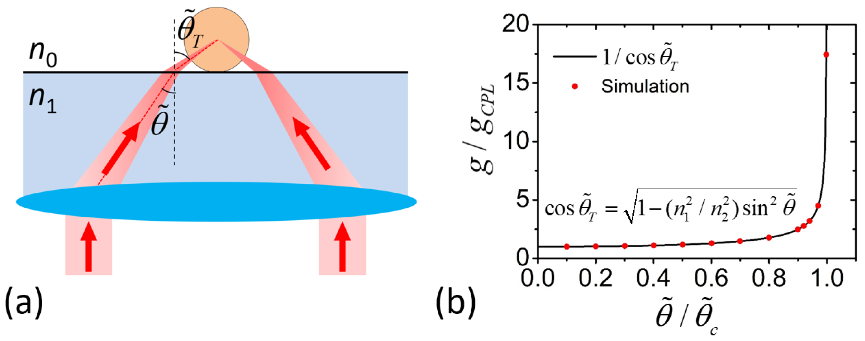
In Equations (32) and (33), is the topological charge of the incident field. = is the wave vector in the substrate. The refractive indexes of the substrate and air are = 1.518 and = 1. As shown in Figure 3a, this vectorial light beam can be regarded as the superposition of the p-polarized plane waves, whose wave vector k lives in a cone with the polar angle of and the azimuthal angle in k-space. The chirality enhancement factor at the focus point (r = 0) is calculated when the polar angle is changed from zero to the critical angle of the total internal reflection, as shown in Figure 3b. When is slightly smaller than the critical angle of , the hotspot region with high optical chirality can be realized near the focus point. The sign of optical chirality is the same with the topological charge m0. Therefore, the scattering energies of and in the definition of are calculated when, = 1 and, = −1 in Equations (32) and (33).
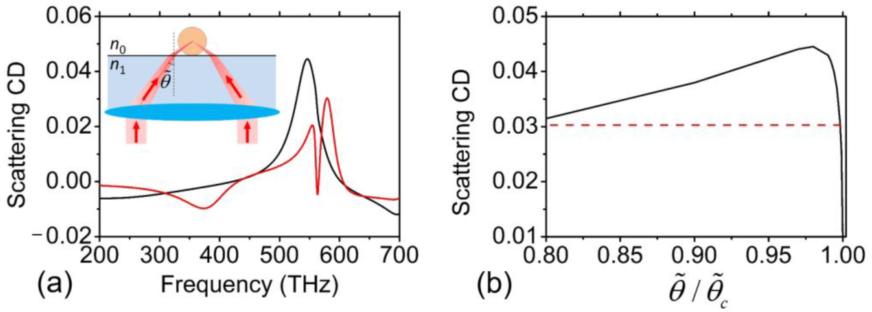
In Figure 4a, the scattering CD spectrum for the sphere in the superchiral field with is calculated as shown by the black curve. For comparison, the red curve represents the scattering CD spectrum for the same sphere in free space when illuminated by CPL light. As discussed above, the chiral response can be largely increased at the Mie resonance wavelength compared with that in the Rayleigh region, where the light wavelength is much larger than the sphere diameter. The peak values of the two CD spectra are 0.0445 and 0.0303 at frequencies of 546 and 579 THz, respectively. It means that, by introducing the superchiral field, the peak value of the scattering CD can be enhanced by 46.8%. The relationship between this enhancement factor and the incident angle has been calculated, as shown by the black curve in Figure 4b. The red dash line represents the level of the peak CD value for CPL light. When the incident angle approaches the critical angle, the CD enhancement is increased at first, and reaches the maximum value at . Then the enhancement factor drops dramatically, which is quite different from the prediction by the chiral dipole model in Figure 3b. To explain the difference, one should notice that the CD value in Figure 3b is for a chiral dipole, which is an individual point. However, the curve in Figure 4b is for the chiral sphere with a diameter of = 75 nm. As it has been reported previously [17], the area of the superchiral hotspot is decreased when is close to , which may make it mismatch the size of the sphere. When , the superchiral hotspot collapses to a point with infinite optical chirality. Around the singularity point, the light field becomes achiral. Therefore, there exists an optimized incident angle for a chiral sphere with finite size.
3. Discussion
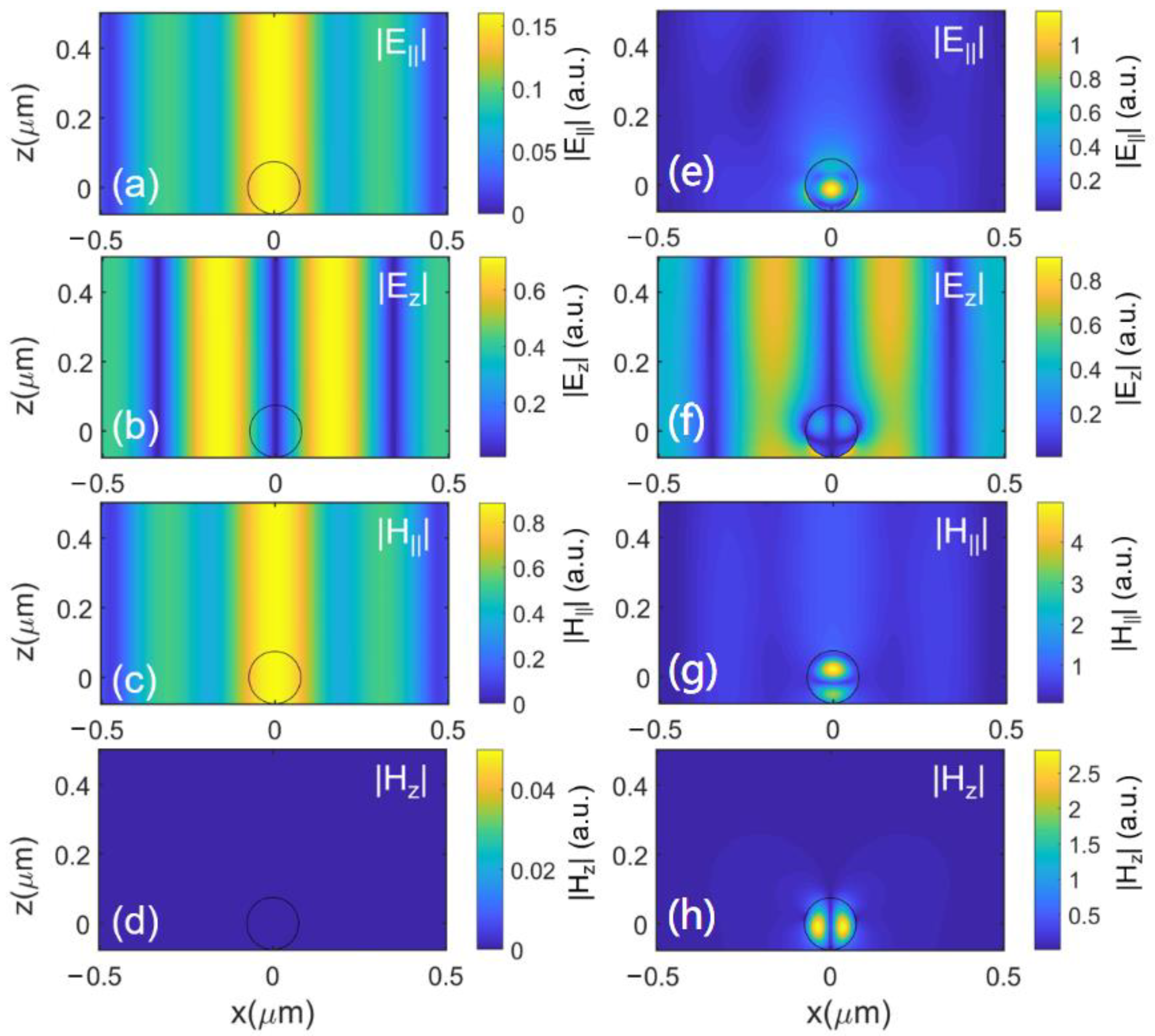
To explain the mechanism of the peak value of the scattering CD for the superchiral field in Figure 4a, the electrical and magnetic fields near the center of the chiral sphere are calculated. In Figure 5a–d, the distributions of the incident field with = 1 are plotted. The frequency of the incident light is 546 THz. For the electric field, is dominant compared with the parallel component in Figure 5b around the focus point. Because the incident beam is entirely p-polarized, the field of is zero.
By employing the theoretical model above, the scattering field by the chiral sphere is calculated in Figure 5e–h. The and of the light field are still the major components, as shown in Figure 5e,g. Because the scattering fields of and both have the helical phase term, the field intensity of and on the z axis is zero in Figure 5f,h. At the frequency of the Mie resonance, the light field is well confined within the sphere. From Figure 5e,g, it can be clearly seen that the resonance along the z direction is formed, and the spatial intensity distribution of and is well separated inside the sphere. The regions of the enhanced magnetic field are both in the upper and lower parts of the sphere. In these regions, the large magnetic field is helpful to increase the chiral response through the coupling between the electric and magnetic fields inside the chiral medium. It should be noted that, under the illumination of the superchiral field, the dip of the scattering CD curve caused by the interaction between ED and MQ disappears. It means that the chiral responses for different orders of the Mie resonances are not independent. In recent years, the scattering by a dielectric sphere has also been employed to enhance the circular dichroism of chiral materials [26,27]. The interaction between different chiral mechanisms should be further studied, which may lead to deeper understanding of the chiroptical effects and the development of novel technologies to distinguish and separate chiral molecules and nanoparticles.
4. Conclusions
In summary, the theoretical method for analyzing light scattering by a chiral sphere in a vectorial light field is developed based on the T-matrix method. Compared with a pure numerical simulation (e.g., finite element method and finite-difference time-domain), this analytical method is more efficient for analyzing the mechanisms of chiroptical phenomena. Especially for a sphere with a subwavelength scale, the scattering field can be calculated accurately by employing a smaller number of vector spherical harmonics. It has been shown that the chiral response by a high-index nanosphere can be enhanced at the frequency of the Mie resonance. Moreover, the superchiral field can be employed to further increase the scattering circular dichroism value when the nanosphere is under resonance condition. Therefore, to obtain the highest chiral signal, both the enhancement mechanisms arising from the near-field nanostructure and the superchiral incident light field can be employed and optimized simultaneously. Further exploration of the chiral interaction between the artificially designed nanostructure (e.g., [28]) and the superchiral field is valuable to the field of optical activity for both fundamental and practical considerations.
Author Contributions
Conceptualization, H.H. and Q.Z.; methodology, H.H.; investigation, H.H.; writing—original draft preparation, H.H. and Q.Z.; writing—review and editing, Q.Z.; supervision, Q.Z. All authors have read and agreed to the published version of the manuscript.
Funding
This study is supported by the National Natural Science Foundation of China under Grant Nos. 62075132 and 92050202.
Acknowledgments
The authors acknowledge the helpful discussion with Mikhail Tribelsky on resonant light scattering by nano-objects during Mikhail Tribelsky visit to Shanghai. It is our honor to contribute to the Special Issue of Physics, which is dedicated to the celebration of his 70th birthday and outstanding achievements.
Conflicts of Interest
The authors declare no conflict of interest.
References
- Barron, L.D. Molecular Light Scattering and Optical Activity; Cambridge University Press: Cambridge, UK, 2004. [Google Scholar]
- Bliokh, K.Y.; Bekshaev, A.Y.; Nori, F. Dual electromagnetism: Helicity, spin, momentum and angular momentum. New J. Phys. 2013, 15, 033026. [Google Scholar] [CrossRef]
- Mun, J.; Kim, M.; Yang, Y.; Badloe, T.; Ni, J.; Chen, Y.; Qiu, C.W.; Rho, J. Electromagnetic chirality: From fundamentals to nontraditional chiroptical phenomena. Light Sci. Appl. 2020, 9, 139. [Google Scholar] [CrossRef]
- Hentschel, M.; Schäferling, M.; Duan, X.; Giessen, H.; Liu, N. Chiral plasmonics. Sci. Adv. 2017, 3, e1602735. [Google Scholar] [CrossRef] [PubMed] [Green Version]
- Zhao, Y.; Askarpour, A.N.; Sun, L.; Shi, J.; Li, X.; Alu, A. Chirality detection of enantiomers using twisted optical metamaterials. Nat. Commun. 2017, 8, 14180. [Google Scholar] [CrossRef] [PubMed]
- Vazquez-Guardado, A.; Chanda, D. Superchiral Light Generation on Degenerate Achiral Surfaces. Phys. Rev. Lett. 2018, 120, 137601. [Google Scholar] [CrossRef] [PubMed] [Green Version]
- Poulikakos, L.V.; Thureja, P.; Stollmann, A.; Leo, E.D.; Norris, D.J. Chiral Light Design and Detection Inspired by Optical Antenna Theory. Nano Lett. 2018, 18, 4633–4640. [Google Scholar] [CrossRef]
- Rui, G.; Hu, H.; Singer, M.; Jen, Y.J.; Zhan, Q.; Gan, Q. Symmetric Meta-Absorber-Induced Superchirality. Adv. Opt. Mater. 2019, 7, 1901038. [Google Scholar] [CrossRef]
- Kuznetsov, A.I.; Miroshnichenko, A.E.; Brongersma, M.L.; Kivshar, Y.S.; Luk’Yanchuk, B. Optically resonant dielectric nanostructures. Science 2016, 354, aag2472. [Google Scholar] [CrossRef] [Green Version]
- Rybin, M.V.; Koshelev, K.L.; Sadrieva, Z.F.; Samusev, K.B.; Bogdanov, A.A.; Limonov, M.F.; Kivshar, Y.S. High-Q Supercavity Modes in Subwavelength Dielectric Resonators. Phys. Rev. Lett. 2017, 119, 243901. [Google Scholar] [CrossRef] [PubMed] [Green Version]
- Zhang, C.; Xu, Y.; Liu, J.; Li, J.; Xiang, J.; Li, H.; Li, J.; Dai, Q.; Lan, S.; Miroshnichenko, A.E. Lighting up silicon nanoparticles with Mie resonances. Nat. Commun. 2018, 9, 2964. [Google Scholar] [CrossRef] [PubMed] [Green Version]
- Svyakhovskiy, S.E.; Ternovski, V.V.; Tribelsky, M.I. Anapole: Its birth, life, and death. Opt. Express 2019, 27, 23894–23904. [Google Scholar] [CrossRef] [PubMed]
- Miroshnichenko, A.E.; Evlyukhin, A.B.; Yu, Y.F.; Bakker, R.M.; Chipouline, A.; Kuznetsov, A.I.; Luk’yanchuk, B.; Chichkov, B.N.; Kivshar, Y.S. Nonradiating anapole modes in dielectric nanoparticles. Nat. Commun. 2015, 6, 8069. [Google Scholar] [CrossRef]
- Wei, L.; Xi, Z.; Bhattacharya, N.; Urbach, H.P. Excitation of the radiationless anapole mode. Optica 2016, 3, 799. [Google Scholar] [CrossRef] [Green Version]
- Tang, Y.; Cohen, A.E. Optical chirality and its interaction with matter. Phys. Rev. Lett. 2010, 104, 163901. [Google Scholar] [CrossRef] [PubMed]
- Tang, Y.; Cohen, A.E. Enhanced enantioselectivity in excitation of chiral molecules by superchiral light. Science 2011, 332, 333–336. [Google Scholar] [CrossRef] [Green Version]
- Hu, H.; Gan, Q.; Zhan, Q. Generation of a Nondiffracting Superchiral Optical Needle for Circular Dichroism Imaging of Sparse Subdiffraction Objects. Phys. Rev. Lett. 2019, 122, 223901. [Google Scholar] [CrossRef]
- Lindell, I.V.; Sihvola, A.H.; Tretyakov, S.A.; Viitanen, A.J. Electromagnetic Waves in Chiral and Bi-Isotropic Media; Artech House: Boston, MA, USA; London, UK, 1994. [Google Scholar]
- Bohren, C.F. Light scattering by an optically active sphere. Chem. Phys. Lett. 1974, 29, 458–462. [Google Scholar] [CrossRef]
- Mishchenko, M.I.; Travis, L.D.; Lacis, A.A. Scattering, Absorption and Emission of Light by Small Particles; Cambridge University Press: Cambridge, UK, 2002. [Google Scholar]
- Lamprianidis, A.G.; Miroshnichenko, A.E. Excitation of nonradiating magnetic anapole states with azimuthally polarized vector beams. Beilstein J. Nanotechnol. 2018, 9, 1478–1490. [Google Scholar] [CrossRef] [Green Version]
- Yang, Y.; Bozhevolnyi, S.I. Nonradiationg anapole states in nanophotonics: Form fundamentals to applications. Nanotechnology 2019, 30, 204001. [Google Scholar] [CrossRef]
- Hernández-Acosta, M.A.; Soto-Ruvalcaba, L.; Martínez-González, C.L.; Trejo-Valdez, M.; Torres-Torres, C. Optical phase-change in plasmonic nanoparticles by a two-wave mixing. Phys. Scr. 2019, 94, 125802. [Google Scholar] [CrossRef]
- Bauer, T.; Orlov, S.; Peschel, U.; Banzer, P.; Leuchs, G. Nanointerferometric amplitude and phase reconstruction of tightly focused vector beams. Nat. Photonics 2014, 8, 23–27. [Google Scholar] [CrossRef] [Green Version]
- Zhan, Q. Cylindrical vector beams: From mathematical concepts to applications. Adv. Opt. Photonics 2009, 1, 1–57. [Google Scholar] [CrossRef]
- Vestler, D.; Ben-Moshe, A.; Markovich, G. Enhancement of Circular Dichroism of a Chiral Material by Dielectric Nanospheres. J. Phys. Chem. C 2019, 123, 5017–5022. [Google Scholar] [CrossRef]
- Ho, C.S.; Garcia-Etxarri, A.; Zhao, Y.; Dionne, J. Enhancing Enantioselective Absorption Using Dielectric Nanospheres. ACS Photonics 2017, 4, 197–203. [Google Scholar] [CrossRef]
- Fernandez-Corbaton, I.; Fruhnert, M.; Rockstuhl, C. Dual and Chiral Objects for Optical Activity in General Scattering Directions. ACS Photonics 2015, 2, 376–384. [Google Scholar] [CrossRef] [Green Version]
Figure 1.
(a) The scattering spectrum of a chiral sphere with a radius of 75 nm under the illumination of linearly polarized light. The optical parameters of the sphere are = 25 (permittivity), = 1 (permeability), and = 0.01 (chirality). The sphere is in free space (refractive index = 1). (b) The contributions to the total scattering energies from three different mechanisms (magnetic dipole, electric dipole, and magnetic quadrupole). (c) The circular dichroism (CD) spectrum of under the illumination of left circularly polarized (LCP) and right circularly polarized (RCP) light.

Figure 2.
A schematic of the theoretical model to analyze light scattering by a chiral sphere on the substrate. The blue and green arrows represent the path of the incident light ( and ) and scattering light ( and ). The red arrows represent the light reflected and transmitted at the interface. represent the reflection matrix.

Figure 3.
(a) The model to analyze light scattering by the sphere in the superchiral field. The incident field is the vectorial Bessel beam with orbital angular momentum of Equations (32) and (33), with the topological charge, = ±1. The refractive indexes of the substrate and air are = 1.518 and = 1. The incident angle is , and the refraction angle is (b) The enhancement factor of the chiral signal from a dipole at the focus (r = 0). g and are the CD factors under the superchiral light and circularly polarized light (CPL) light. represents the critical angle of total reflection.

Figure 4.
(a) The black curve represents the scattering CD spectrum of a chiral sphere on the substrate under the illumination of the superchiral field with . The red curve is the scattering CD spectrum of the chiral sphere in free space excited by CPL. (b) The peak value of the scattering CD spectra with a different value of . The red dash line represents the peak value of the scattering CD spectra under the illumination of CPL, when the sphere is in free space.

Figure 5.
The light field of the vectorial Bessel beam above the air–dielectric interface. The topological charge is = 1. (a–d) The distributions of , , , and without the chiral sphere. and ( and ) represent the electric (magnetic) field components parallel and vertical to the interface. (e–h) The distributions of , , , and scattering by the chiral sphere. The incident light frequency is 546 THz.

Publisher’s Note: MDPI stays neutral with regard to jurisdictional claims in published maps and institutional affiliations. |
© 2021 by the authors. Licensee MDPI, Basel, Switzerland. This article is an open access article distributed under the terms and conditions of the Creative Commons Attribution (CC BY) license (https://creativecommons.org/licenses/by/4.0/).
Share and Cite
MDPI and ACS Style
Hu, H.; Zhan, Q. Enhanced Chiral Mie Scattering by a Dielectric Sphere within a Superchiral Light Field. Physics 2021, 3, 747-756. https://0-doi-org.brum.beds.ac.uk/10.3390/physics3030046
AMA Style
Hu H, Zhan Q. Enhanced Chiral Mie Scattering by a Dielectric Sphere within a Superchiral Light Field. Physics. 2021; 3(3):747-756. https://0-doi-org.brum.beds.ac.uk/10.3390/physics3030046
Chicago/Turabian StyleHu, Haifeng, and Qiwen Zhan. 2021. "Enhanced Chiral Mie Scattering by a Dielectric Sphere within a Superchiral Light Field" Physics 3, no. 3: 747-756. https://0-doi-org.brum.beds.ac.uk/10.3390/physics3030046