
An IoT-Based Mobile System for Safety Monitoring of Lone Workers


LabGis Laboratory, Computer Science Department, University of Salerno, 84084 Fisciano, Italy
*
Author to whom correspondence should be addressed.
IoT 2021, 2(3), 476-497; https://0-doi-org.brum.beds.ac.uk/10.3390/iot2030024
Submission received: 31 May 2021
/
Revised: 27 July 2021
/
Accepted: 28 July 2021
/
Published: 3 August 2021
(This article belongs to the Special Issue Mobile Computing for IoT)
Abstract
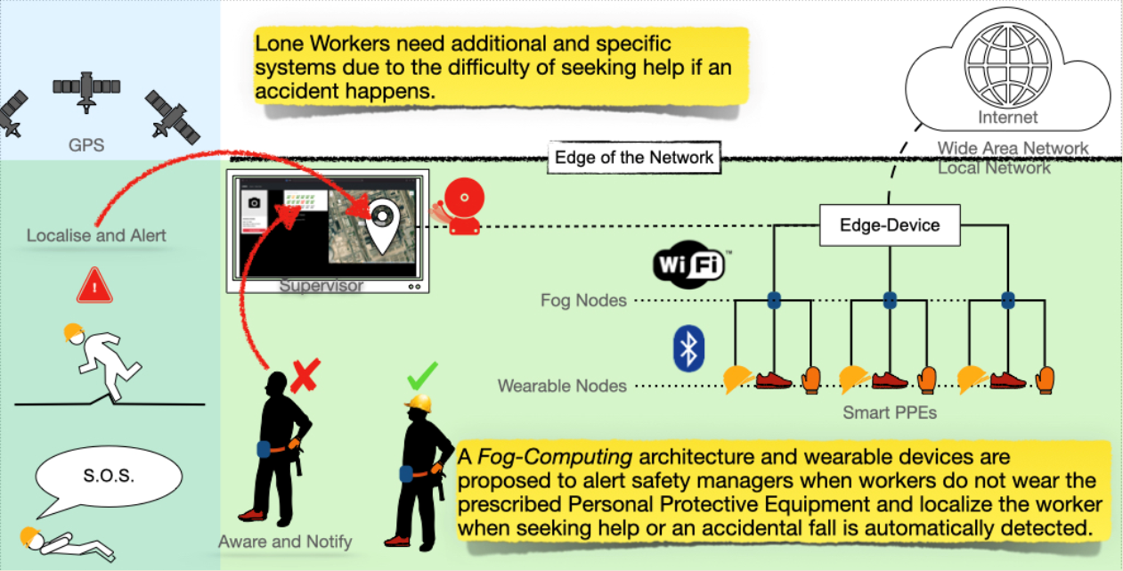
:The European Agency for Safety and Health at Work considers Smart Personal Protective Equipment as “Intelligent Protection For The Future”. It mainly consists of electronic components that collect data about their use, the workers who wear them, and the working environment. This paper proposes a distributed solution of Smart Personal Protective Equipment for the safety monitoring of Lone Workers by adopting low-cost electronic devices. In addition to the same hazards as anyone else, Lone Workers need additional and specific systems due to the higher risk they run on a work site. To this end, the Edge-Computing paradigm can be adopted to deploy an architecture embedding wearable devices, which alerts safety managers when workers do not wear the prescribed Personal Protective Equipment and supports a fast rescue when a worker seeks help or an accidental fall is automatically detected. The proposed system is a work-in-progress which provides an architecture design to accommodate different requirements, namely the deployment difficulties at temporary and large working sites, the maintenance and connectivity recurring cost issues, the respect for the workers’ privacy, and the simplicity of use for workers and their supervisors.

1. Introduction
According to the European Agency for Safety and Health at Work [1], accidents at work represent a high cost for companies and, above all, a much higher cost for the victims and their families. Compared with the gross national product, for most countries, this cost ranges from 2.6% to 3.8%, thus identifying a phenomenon with a social and economic impact recognized at different institutional levels.
While companies have the ethical and legal accountability to ensure that their workers, the workers of subcontractors working in their facilities, and any other person visiting their facilities remain safe at all times, the European Union acts through its organisms to define the appropriate procedures to regulate this topic. In particular, the European Occupational Health and Safety (OSH) recommendations assign personal protective equipment (PPE) the highest preventive measures effectiveness, while the European Economic Community (EEC) directive about its usage in the workplace affirms that when risks cannot be avoided or sufficiently limited through procedures and technical means of collective protection, PPE must be used [2]. As for the national accident insurance institutes of the Member States, they are in charge of verifying that companies follow the rules by inspecting the workplaces and issuing fines if they do not comply. However, the same European agency also aims to spread incentive systems across the continent, so that those institutes usually offer some tax rebates to the companies, providing an additional incentive to investigate novel and suitable PPE.
Despite this awareness, however, the number of accidents at work that cause serious damage to people remains high. This negative trend is explained by the lack of a fundamental requirement. Although the success of those preventive means certainly depends on the right choice of PPE and their correct fit, it is also essential that they are worn all the time, and this requirement is often not satisfied, as stated by a Kimberly-Clark survey [3]. According to the survey, 82% of safety professionals affirm that they observed workers in their organizations failing to wear the required PPE. Reasons for noncompliance cited by respondents of survey [3] were:
- Uncomfortable.
- Too hot.
- Blamed for decreased productivity or an inability to perform tasks.
- Unavailable near the work task.
- Ill-fitting.
- Unattractive looking.
The Kimberly-Clark survey results remark the need for a comfortable PPE design and that it is crucial to verify that they are worn all the time. Moreover, when considering people working by themselves without close or direct supervision, isolated from other workers, safety precautions assume even higher importance. Thus, in addition to the same hazards as anyone else, these Lone Workers are at greater risk as they have no one around to ask for help in the event of an accident. Hence, additional systems are required to keep in touch and monitor Lone Workers remotely. In particular, innovative solutions are needed to trigger alarms automatically or manually, know their location, and recognize that they have returned to their base once they have completed their task.
Smart Personal Protective Equipment
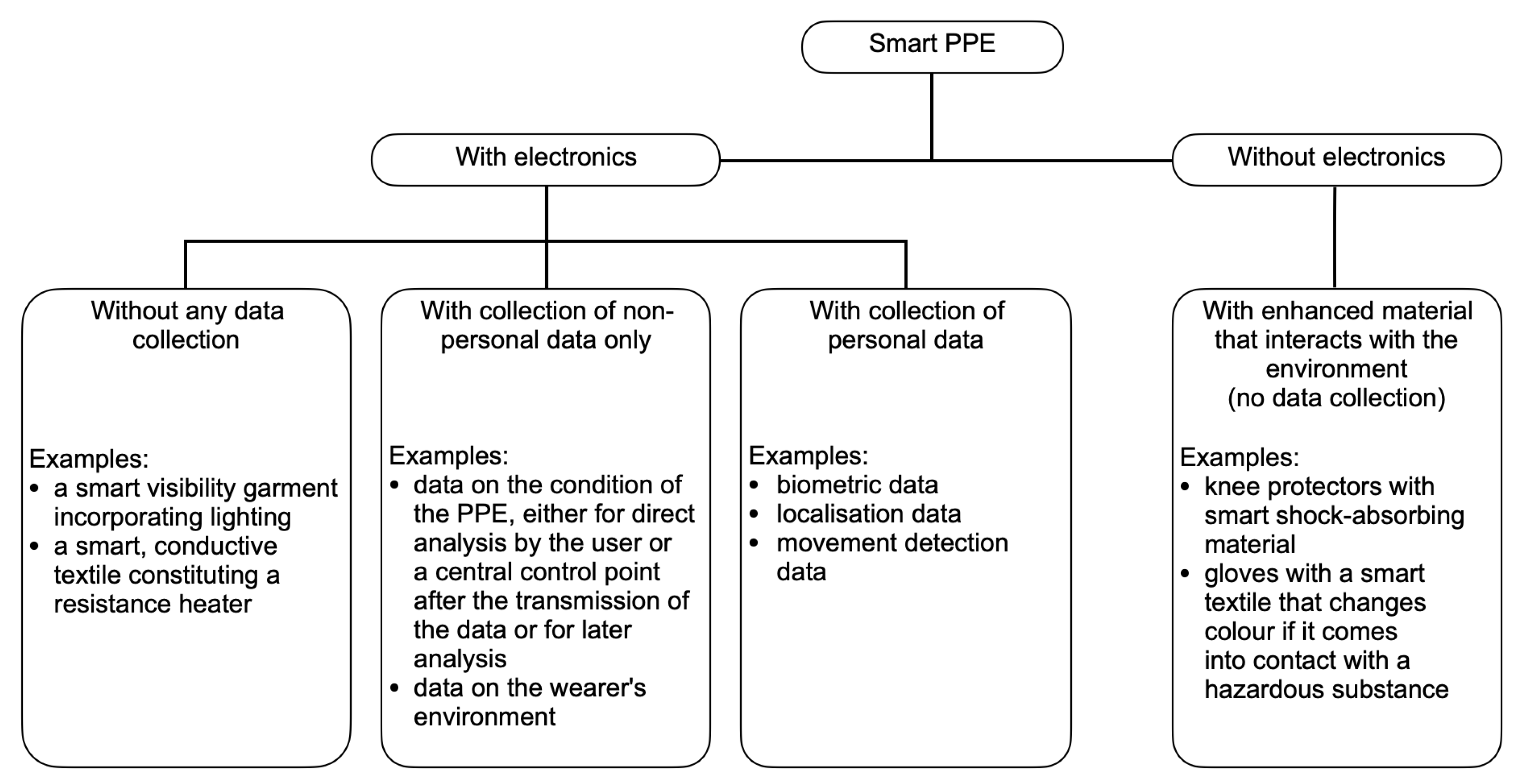
A recent discussion paper [4] by the European Agency for Safety and Health at Work describes the smart PPE as an intelligent protection for the future. Although a definition from European standardization is still only a proposal, it is common to define the smart PPE as ‘the combination of traditional PPE with intelligent elements’. As shown in Figure 1, most of the smart elements are electronic.
Of these, most collect data and need to transmit it in near real-time if continuous remote monitoring of workers’ safety status is required. If these solutions require expensive or complex infrastructure to install at work sites, they become less attractive to employers and even unsuitable for some outdoor workplaces.
Smart PPE should attract its adoption, and for this purpose, in [4] it is clearly highlighted that delivering clear safety advantages and keeping low the expenses are essential prerequisites. Furthermore, since a good PPE is a PPE used all the time, a smart PPE should be accepted by the employees and used seamlessly on the working sites.
Based on the above considerations, the research direction at the Laboratory of Geographic Information Systems (LabGIS) of the Computer Science Department (University of Salerno) was to identify solutions that let the safety professionals verify the continuous use of PPE and offer the possibility of a prompt rescue in the case of an accident.
To achieve these goals, several requirements affecting different design phases have been recognized to be satisfied. In particular, besides the need to design a solution based on a simple infrastructure having a convenient cost at purchase time, it is necessary to make the solution attractive and feasible from the employers’ perspective. This implies that the electronics should have a minimal impact on traditional PPE while transforming it into smart PPE and the way the data is collected during its usage should not worry the employees about being spied during the working time. Finally, to promote the usage of smart PPE by employees, the continuous use of smart PPE has to be monitored and the worker’s position has to be known when a rescue is required.
The work-in-progress research described in this paper represents the methodological and technological solution to these requirements. In particular, by heeding the effectiveness of a Fog-Computing infrastructure, this paper proposes a practical and affordable solution based on specific hardware to transform traditional PPE into smart PPE and realize the required wearable sensors. Moreover, it is deployable even in an open and large work site, with the requirement of limited Cloud resource use, exclusively for secondary tasks, making the use of the Internet connection optional and the entire system tolerant to an unreliable Internet connection.
The paper is organized as follows, Section 2 recalls some relevant related work. An overview of the designed architecture and used technology is given in Section 3. The proposed solution is then described in Section 4. Section 5 depicts a possible scenario to illustrate an emblematic deployment. The discussion and conclusion sections follow. Finally, a description of in-lab tests with their preliminary results is given in Appendix A.
2. Related Work
This section collects papers that recommend various technical solutions to improve workers’ safety through smart PPE and wireless sensors. In particular, they propose solutions designed to prevent accidents or achieve quick rescue when an accident occurs, these being the aspects that this research work challenges to improve.
In [5], Shabina proposes a smart helmet equipped with sensors to monitor the working environment of underground mines workers. In [6], the authors propose a dedicated wireless sensor to prevent fatal accidents with vehicles on construction sites. With [7], Haibo Li proposes to use RFID tags and readers to make port workers aware when they are in a dangerous zone, as within an operating area of a crane. In [8], the authors propose a prototype for a wearable tactile sensory system to warn the construction workers about potential dangers. Notifications are sent by a tactile language system. In [9], recognizing the growing use of IoT sensors for workers’ safety, the authors propose a framework to collect and manage those devices. They also describe a sensor-rich smart helmet developed to validate their idea.
A system capable of detecting anomalous situations is proposed in [10], which uses waist-mounted and environmental sensors. It warns workers in case of uncertainty and communicates their position only in case of an accident, thus preserving their privacy during ordinary working situations. In [11], the authors propose multiple wearable sensors to monitor environmental and workers’ physiological parameters. The wearable sensors can communicate among them and transmit data to a gateway. Once dangerous situations are detected, the sensor node provides users and the remote site with a notification and a warning mechanism.
The use of a neural network solution to detect if workers are wearing helmets during their activities is proposed in [12,13]. In [14], Ravikiran and Sen argue that the video detection of safety gear on workers could be an adequate solution in the context of industrial safety by introducing a safety gear detection dataset consisting of 5 k images with hardhats, vests, gloves, and goggles. In [15], the authors describe a smart IoT device developed to detect human falls and monitor workers’ vital parameters, by sending an SMS notification for immediate aid when such signals are indicating an accident. In [16], the authors propose wearable devices and Edge-Devices to train a neural network model to detect worker’s falls by using Deep Learning video cameras. They claim an achieved falls detection performance above 94%. In [17], Jayasree and Kumar propose a helmet embedded with an accelerometer and a gyroscope sensor to monitor construction workers’ physical conditions and send a notification to the contractor via the mobile. In [18], the authors propose a wearable device to enhance firefighters’ safety in forest fires. The device has sensors to detect a probable accident and a GPS based locating-solution to follow lone workers during risky activities and reach them promptly in case of aid request.
In the following subsections, the aforementioned papers and the present proposal are compared by classifying them in terms of the technologies they used and goals they claim to achieve.
2.1. IoT Technologies
This first grouping refers to IoT solutions, which use wireless sensors and communicate data to a remote server. Papers [5,6,7,8,9,10,11] are included in this category. They mainly claim to address the issue of warning workers when some environmental parameters or their position indicate a potential imminent risk.
Remarks: Although they use technologies similar to the proposed solution, their goals are different. Indeed, only papers [10,11] could be suitable for Lone Workers while the others are most oriented to warn workers of the imminent risk and do not keep them in communication with colleagues. Anyhow, none of them consider confirming that workers actually wear PPE during the working time, which is an essential improvement of the solution proposed in this paper.
2.2. Machine Learning Solutions
This grouping includes solutions using advanced machine learning (ML) technologies to achieve their goals [12,13,14].
Remarks: Although their solutions use a very different methodology from the one proposed in this paper, they claim to prevent accidents by supervising the PPE usage, which is a shared goal. On the other hand, they do not propose any solution to acknowledge the workers’ position to allow for a quicker rescue if an accident occurs, which is a significant advantage claimed in the present proposal.
Moreover, it is worth noticing that the use and installation of smart cameras contrast with the expectation of a simple and low-cost installation when considering the Lone Workers condition, as, in this case, it should be necessary to install a camera for each of them.
2.3. Wearable Sensors
Papers [15,16,17,18] propose solutions to autonomously alert rescuers when wearable sensors record a fall detection or other foreseeable accidents.
Remarks: Although using wearable sensors and detecting human falls are methods and goals shared with the solution proposed, the cited papers do not combine their solution with one conceived to verify if workers are wearing the PPE correctly, which is a fundamental aim of the present paper.
2.4. Recap
The research work described in the following sections proposes a comprehensive solution that, through low-cost devices embedded in a “Fog-Computing” architecture, provides for both continuous monitoring of the PPE usage and an approach for rapid rescue when an incident occurs, which represents the distinguishing features with respect to the existing literature.
In addition, the proposed solution addresses the challenges of deployment at large and temporary work sites, reduces recurring maintenance and connectivity costs, and guarantees the workers’ privacy, while having little impact on their usual activities, thus achieving the essential requirements for a functional solution with smart PPE, as argued in the previous section.
3. Preliminaries
This section contains an overview of architectures and technologies adopted in the proposed solution.
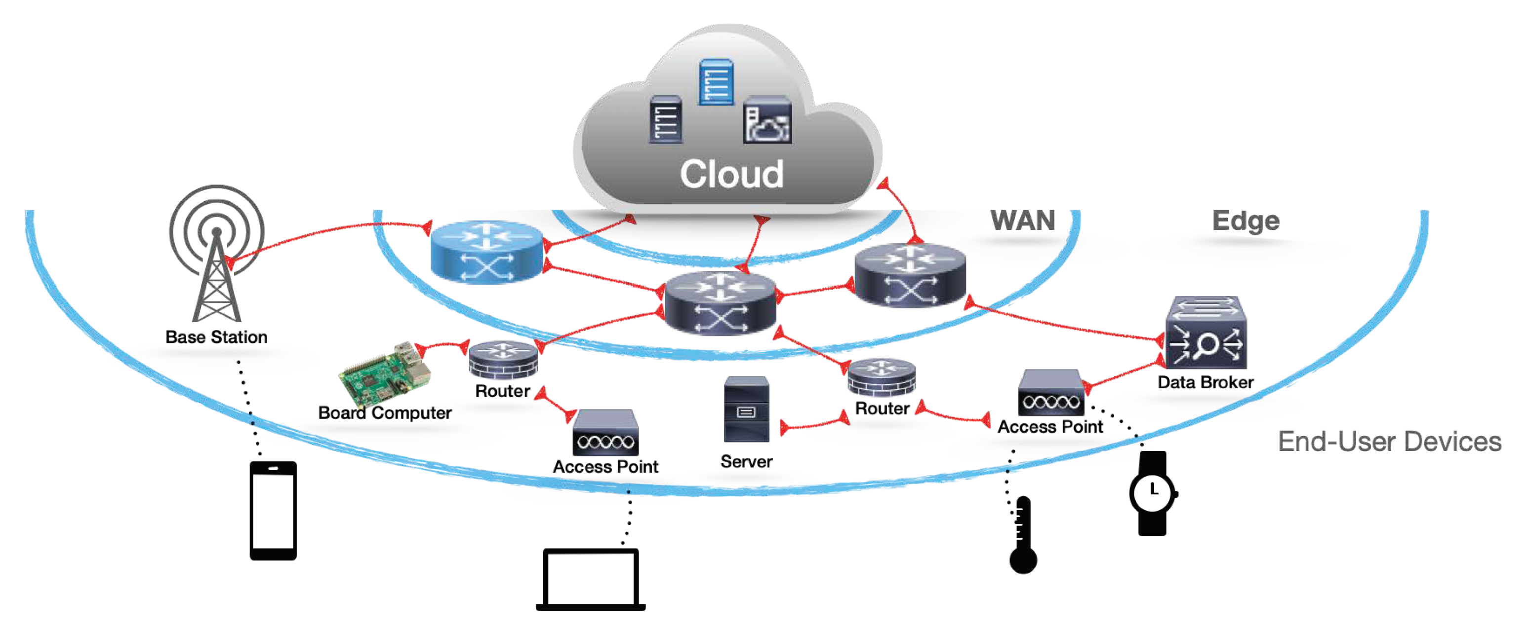
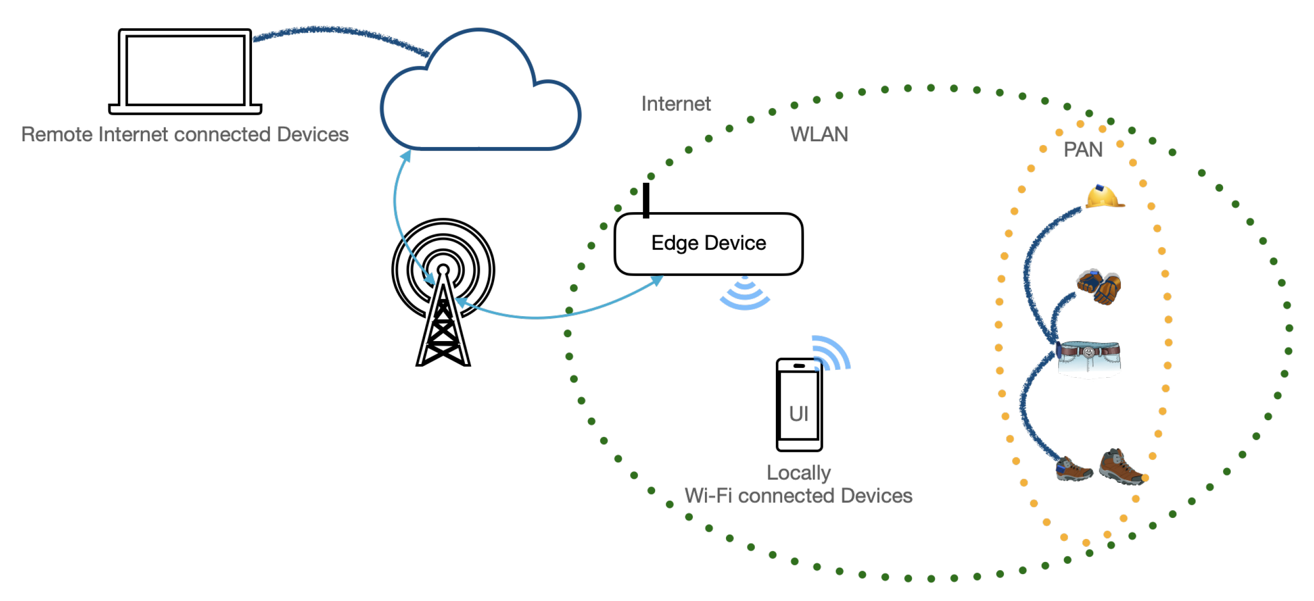
The Edge-Computing [19] paradigm has spread as the number of the Internet Protocol (IP) connected devices has increased dramatically. This paradigm aims to move part of the computation from Cloud resources to the Edge of the network, closer to the data sources, because shortening the network path decreases the latency usually generated by the Internet connection to the Cloud, and at the same time, reduces the occupancy of the Internet bandwidth. The need for this recent approach is further motivated by the Cisco Annual Internet Report (2018–2023) [20], which states that the IP-connected devices will be over three times the world population by 2023, thus boosting issues for the Internet connections. Moreover, when the IP-connected devices are used for real-time actions, unreliable or slow network connections could potentially pose a dangerous situation.
Figure 2 depicts a typical Edge-Computing architecture, having a Wi-Fi area as the Edge of the network for all the wireless connected devices, and some Edge-Devices between the end-user devices and the wide area network (WAN).
3.1. Fog-Computing
A Fog-Computing solution is an Edge-Computing architecture made up of a layered network [21,22] whose nodes, the Fog-Nodes, must provide connectivity services as well as computational and storage resources, if required.
It was in 2010 at the CISCO/MBARI meeting that Flavio Bonomi presented his different vision of Edge-Computing, and Ginny Nichols, an attendee of the meeting, suggested the “Fog-Computing” term to highlight that, “while the Clouds are high in the sky, the Fog is experienced close to the ground, i.e., close to the users”, as she explained. In fact, the primary purpose of Fog-Computing is to distribute computation closer to data sources and users, thus avoiding or decreasing the use of Cloud resources when they are not essential. Moreover, the growing availability of single-board computers, with low power, low cost, and high computational capacity, promoted such a Fog-Computing solution [23,24], promising low latency distributed solutions without relying on an unpredictable and costly Internet connection.
In this paper, a Fog-Computing architecture is adopted, since placing the Fog-Nodes on a local area network (LAN) offers the opportunity to avoid the Internet connection for all the features that do not need a wide geographical distribution.
3.2. IoT Protocols
A reliable and efficient communication protocol is paramount for any distributed system as well as for a Fog-Computing Architecture. Thus, the solution described in this paper adopted the Message Queuing Telemetry Transport (MQTT) [25], one of the most used IoT communication protocols. It is an OASIS standard lightweight messaging protocol based on the publish/subscribe pattern. The publish/subscribe pattern [26] offers asynchronous communication among network nodes in almost real-time. Based on a client/server pattern, publishers (the clients) publish messages to a specific Topic connecting to a known Broker (the server), which will forward it to any subscribers (other clients) of such a Topic [27].
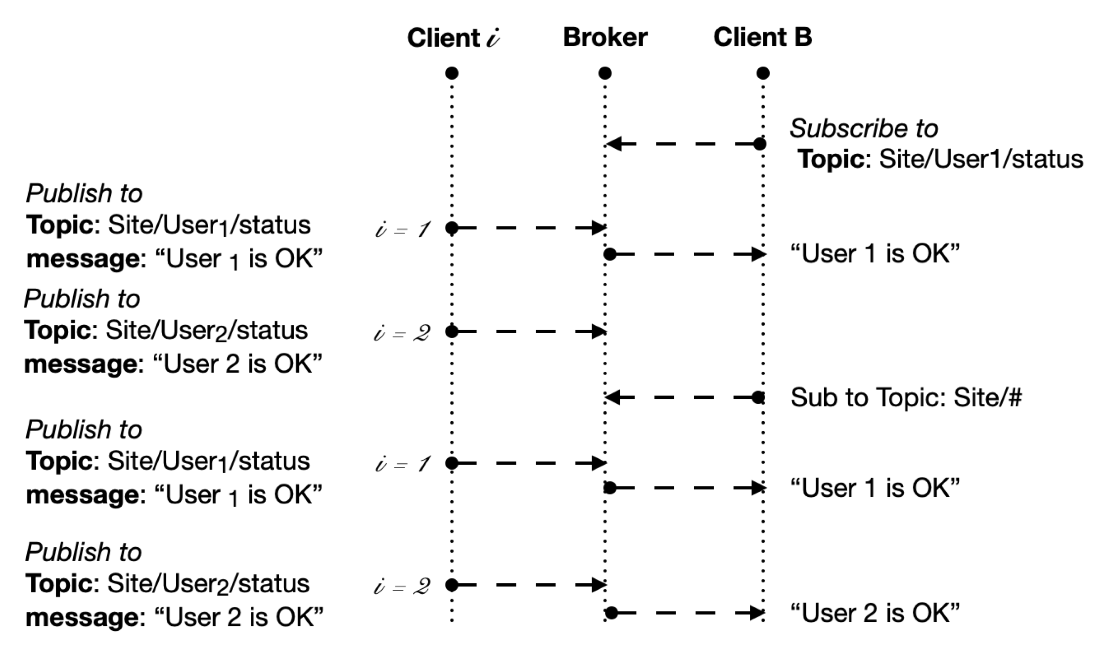
The MQTT Topic is what it precisely means, i.e., the subject of the content of the messages. It is expressed as a string, which has a hierarchical structure similar to a file path. For example, the proposed solution assumes that a Topic identifies a work site, while subtopics identify its workers, so that, if “ is the Topic of the site, “ addresses the ith worker’s Topic. Furthermore, for each worker it is possible to define a subtopic “status”, so that “ is the Topic to which the status of ith worker will be published, where .
The MQTT protocol allows the use of wildcards as a filtering possibility. In this way, clients interested in all users’ status, working on , can subscribe to the Topic “, where the wildcard # at the end of string offers the possibility of being notified about all the messages published on every Topic below “”, i.e., all messages about the status of all users at that site (Figure 3).
Alternatively, clients interested in the status of a given working on , can subscribe to the specific Topic “” and receive all messages strictly related to that worker.
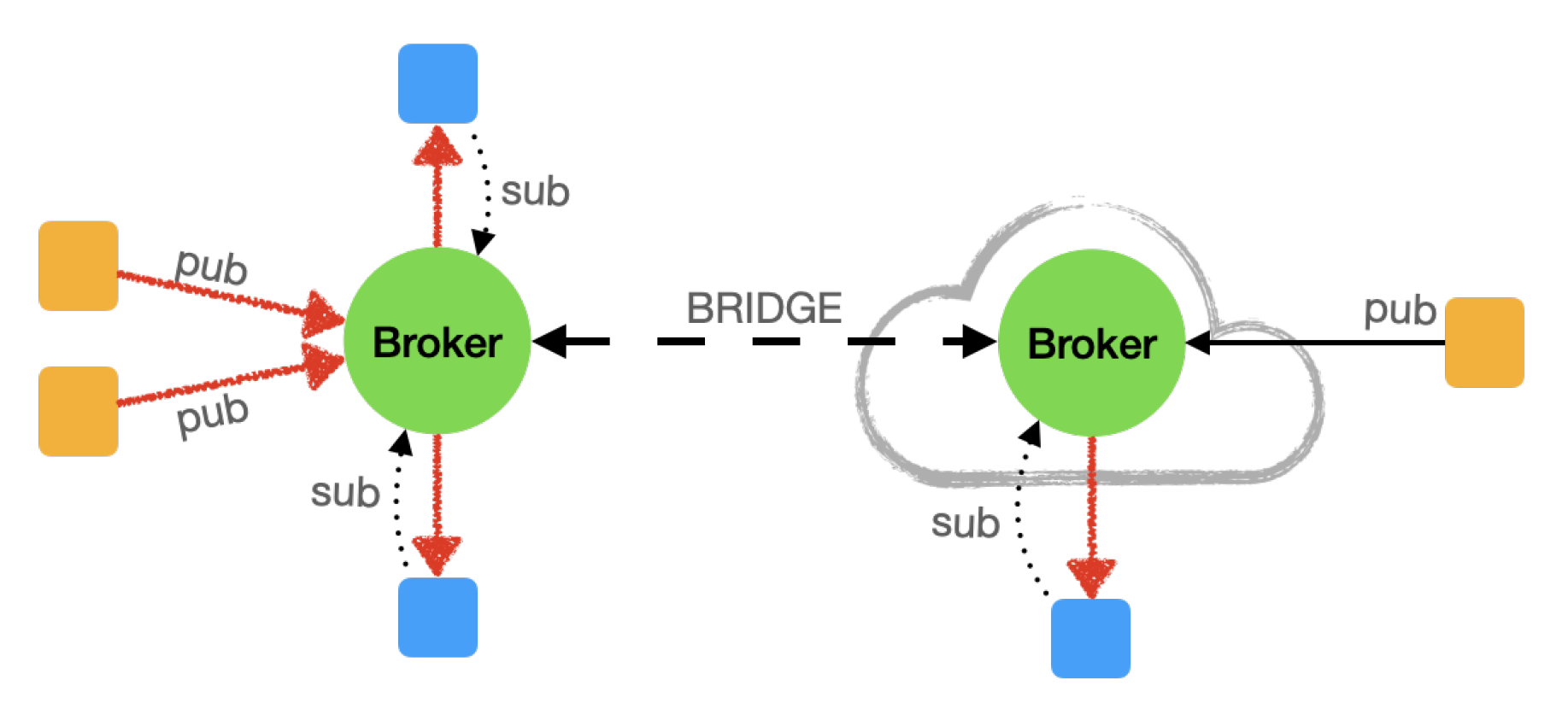
In such a pattern, the connection between publishers and subscribers is managed by the Broker. More that one Publisher can publish on the same Topic and more that one Subscriber can Subscribe to the same Topic. Publishers and subscribers do not need to know each other, they only need to know the address of the Broker to connect.
A Broker can work stand alone or Bridged with another Broker to have a load-balanced, a mirrored server or to permit access to the same Topics by two different addresses (Figure 4).
4. The Monitoring System for Lone Workers
The goal of this section is to describe the architecture, the hardware, and the software of the proposed solution, designed to achieve the features stated in the previous sections and summarized as follows:
- Verifying that workers effectively wear the helmet, gloves, and protective footwear to prevent accidents, and alerting the safety professionals if these conditions are not met;
- Alerting the rescuers as soon as the sensor detects a human fall or a worker deliberately calls for help, informing rescuers of the victim’s position for a fast response.
4.1. The Underlying Architecture
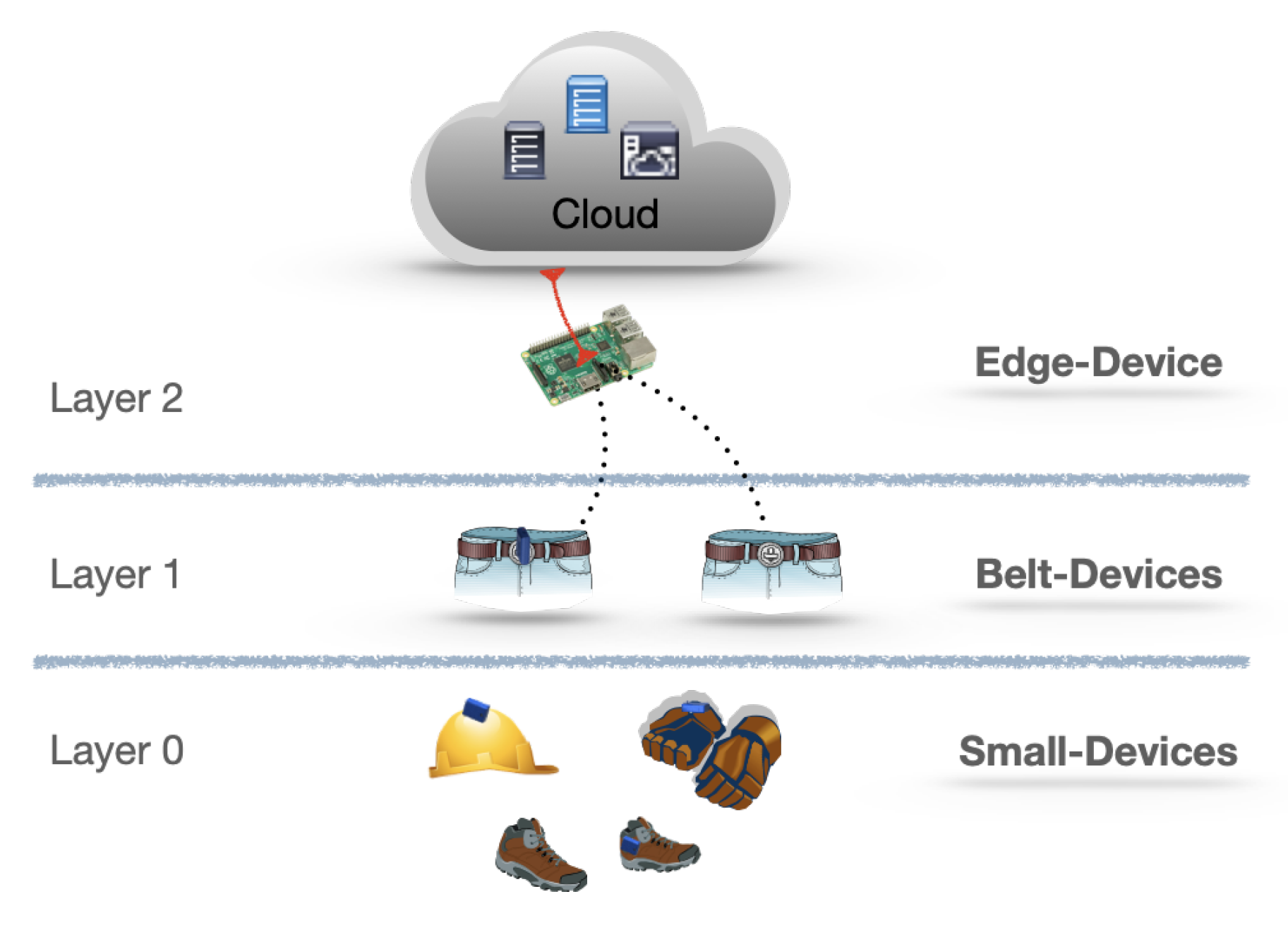
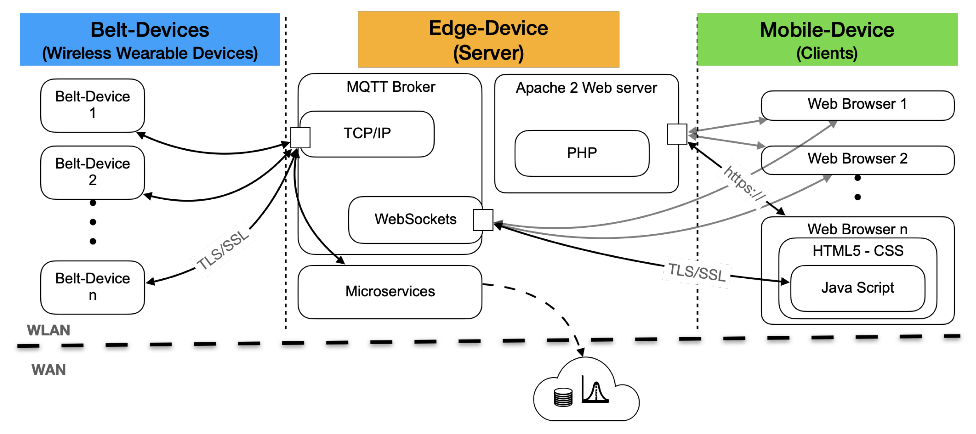
The underlying architecture of the proposed solution derives from the generic Edge-Computing paradigm, introduced in the previous sections and depicted in Figure 2. While the origins and the most relevant features, which differentiate an Edge-Computing architecture from the Fog-Computing [22], are given in Section 3.1, Figure 5 schematizes the layers of the latter as applied to the proposed solution.
The Small-Devices, which make the PPE smart, represent the lower layer. In a Fog-Computing architecture, the lower layer is made up of nodes that do not supply connectivity to others nodes, hence, in the present proposal, the Small-Devices are the end nodes of the architecture.
The Belt-Devices, worn by each worker, represent the first layer of Fog-Nodes, providing connectivity and elaboration resources to the lower nodes. Finally, a single Edge-Device connected to the Cloud resources through the Internet connection is the upper layer of Fog-Nodes.
4.2. The Hardware Components
4.2.1. Small Embedded Devices
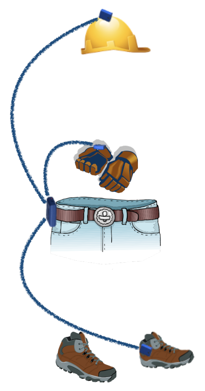
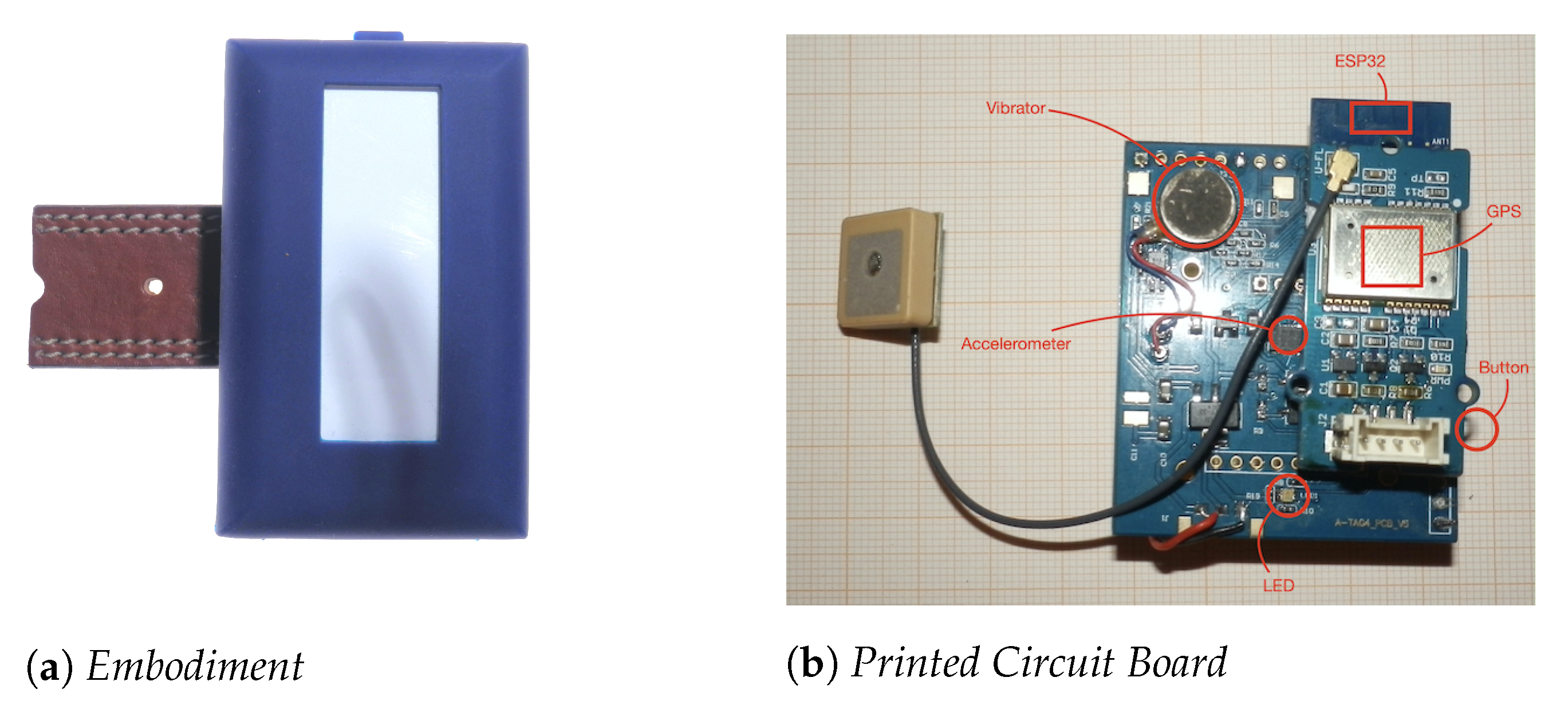
Attached to each PPE, the Small-Devices, made up of an nRF52832 [28] Bluetooth 5.0 low energy module, form a personal area network (PAN) with the associated Belt-Device, as shown in Figure 6.
They are not invasive by design, and their cases are entirely made up of soft silicon rubber to be comfortably wearable, suitable to embed in the fiber of gloves or shoes and inside the helmet (Figure 7).
These devices, powered by a primary (non-rechargeable) lithium battery, can last years thanks to their low power. The long-lasting battery for these devices is critical to drastically reduce the maintenance and cost of ownership for the proposed solution.
4.2.2. Belt-Devices
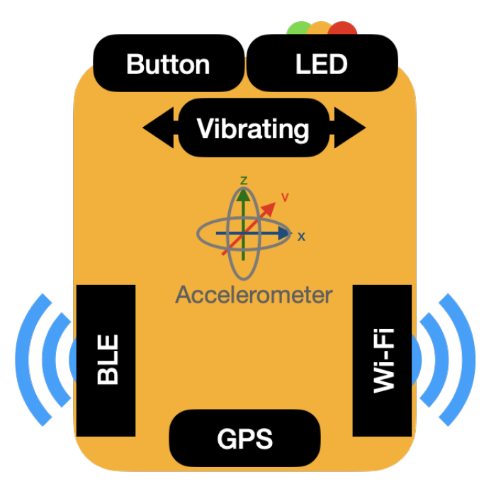
The Belt-Devices have an accelerometer, a GPS module, Wi-Fi, and Bluetooth Low Energy (BLE) connectivity. Their user interface has one push button to acquire inputs from the user, as well as a tricolor LED and a vibrating device to give output to the user (Figure 8).
A prototypical experimenting system was made up of an ESP32 module [29], featuring a rich Micro Controller Unit (MCU) with integrated Wi-Fi and Bluetooth connectivity, an ADXL345 accelerometer [30] circuit, and an additional GPS module [31].
The size of the Belt-Devices (Figure 9) is adequate to be used with protecting gloves. They are rugged and silicon covered to be resistant to fall and water. Powered by a lithium-ion rechargeable battery, they can last more than one working shift.
4.2.3. The Edge-Device
The Edge-Device offers Wi-Fi connectivity and performs as a local server for Web application and micro-services. Additionally, it acts as a local MQTT Broker, where all locally connected devices publish and subscribe to exchange messages. Whenever an Edge-Device cannot guarantee full Wi-Fi coverage in large sites, additional Wi-Fi extenders can expand the covered area.
The Raspberry Pi with its Raspberry Pi OS is a straightforward and cheap solution to act as the Edge-Device. The Raspberry operating system is a Debian Linux distribution compliant with the Mosquitto MQTT Broker and all necessary packages to obtain a LAMP server, namely Linux OS with Apache, MySQL, and PHP.
LAMP is a proven set of software to deliver high-performance Web applications. Mosquitto is an open-source MQTT broker of Eclipse foundation [27,32], which also allows the use of WebSockets [33]. WebSockets are a two-way communication model between a browser and a server over TCP without opening multiple HTTP connections. Furthermore, Mosquitto is compliant with the MQTT Quality of Service (QoS), offering three levels of QoS, namely QoS Level 0 that sends the message only once and does not verify if the message arrived at the destination; QoS Level 1 that sends the message at least once and checks the delivery status; QoS Level 2 that sends the message exactly once utilizing the 4-way handshake. Although it is impossible to have a message loss at this level, it involves longer end-to-end delays.
In [34] the authors suggest a correlation analysis of end-to-end delay and message loss under different QoS levels and payloads, allowing appropriate QoS selection for the proposed solution. Since the repeated messages do not affect the results as well as a slight delay in the message reception, the QoS 1 has been chosen for the proposed case.
Furthermore, the Raspberry boards have programmable General Purpose Input/Output Ports (GPIO), usable to activate sounding alarms triggered by Emergency Events. Finally, an Access Point connected to the Ethernet port of Raspberry creates a Wi-Fi local network area with a ray ranging from 75 to 100 m in an open area.
4.3. Networking
The network plays an important role for the proposed solution since the system nodes need reliable communications to offer their services.
The Small-Devices communicate with the associated Belt-Device by BLE technologies, creating a PAN for each involved worker. The Belt-Device communicates with the Edge-Device by Wi-Fi connection and MQTT protocol. The Edge-Device communicates with remote and Cloud resources by the Internet connection (Figure 10).
4.4. The Software
Communication among the components of the system is the most crucial part of the solution. The devices are seen as stand-alone Fog-Nodes that communicate among them delivering their services.
4.4.1. Communication between Small-Devices and Belt-Device
The BLE offers low-cost and interoperable wireless connectivity for compact battery-powered applications. The technology is highly efficient, minimizing the energy required to transfer data. It is secure, specifying features to ensure confidentiality, integrity, and privacy.
Bluetooth technology uses the principles of “inquiry” and “inquiry scan” devices. According to the Bluetooth Core Specification [35], a BLE Client application can discover services offered by other BLE Server devices in its proximity. The Small-Devices embedded in the PPE behave as BLE Servers, offering Alert Notification Services (ANS) [36] to the devices in their proximity. The Belt-Devices, instead, behave as a BLE Client that will use those services. Once the Belt-Device has discovered the BLE Servers in its proximity, it memorizes such a connection, alerting the application when one of this connection is weak or lost. Since the Small-Devices have a switch that turns the circuits on when the embedding PPE is worn, a loss of connection indicates that the safety gear is dismissed.
4.4.2. Communication between Belt-Devices and Edge-Device
The Belt-Devices communicate with the Edge-Device using Wi-Fi Connectivity and the MQTT protocol. As the MQTT communication is bidirectional, Belt-Devices can be both publisher and subscriber at the same time. In this way, the same Belt-Device can publish messages to Edge-Device but it can also receive messages from other networked services.
4.4.3. The Firmware
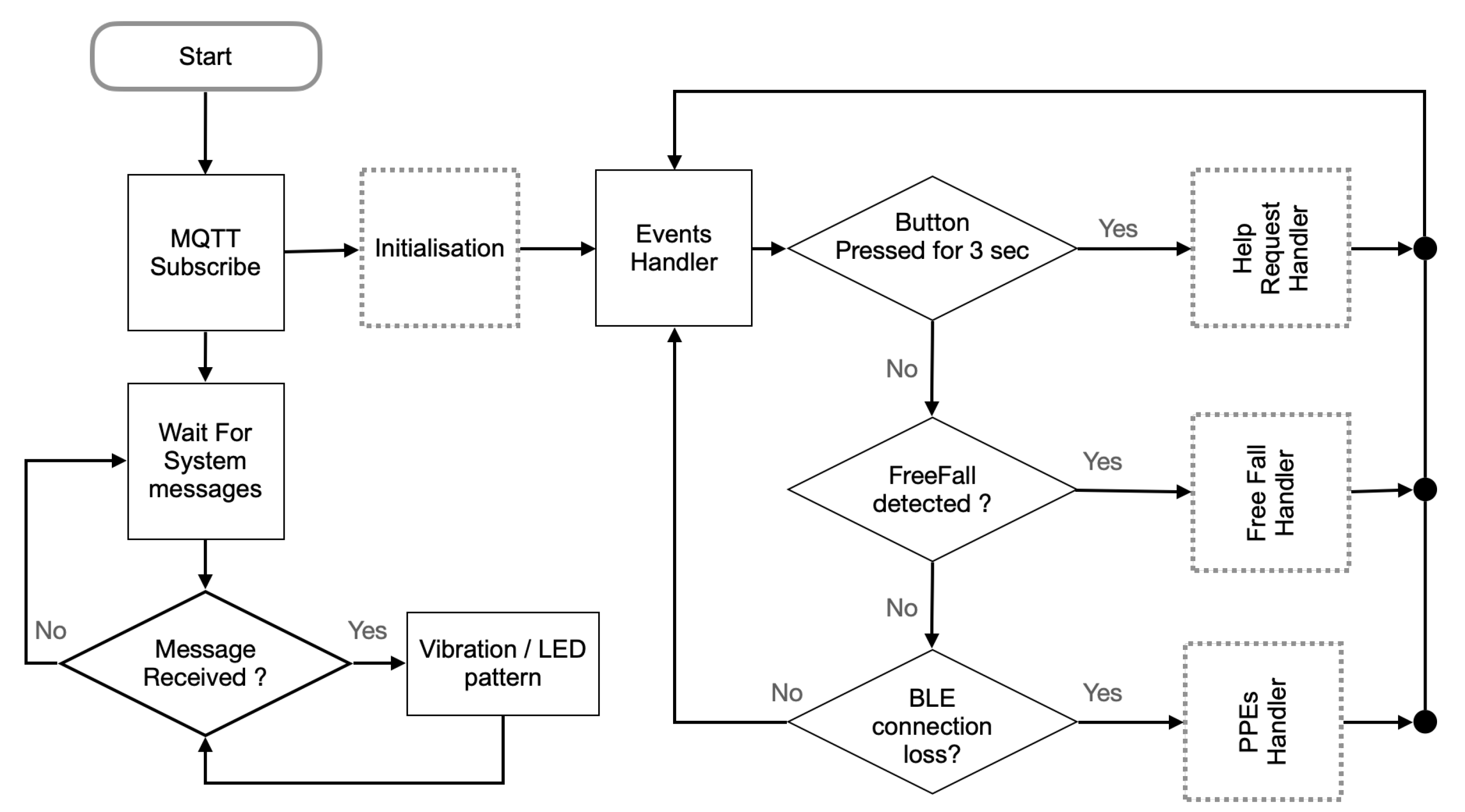
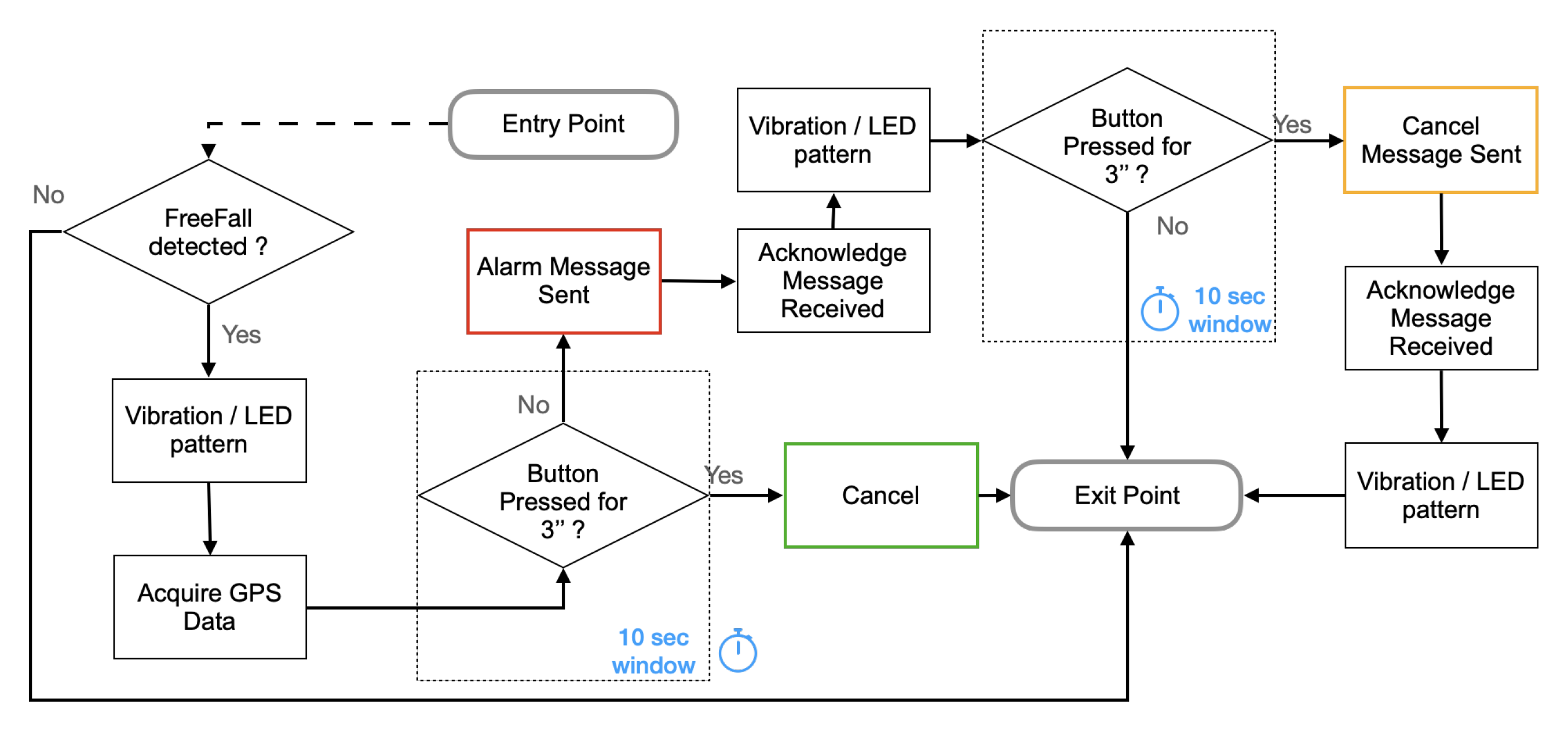
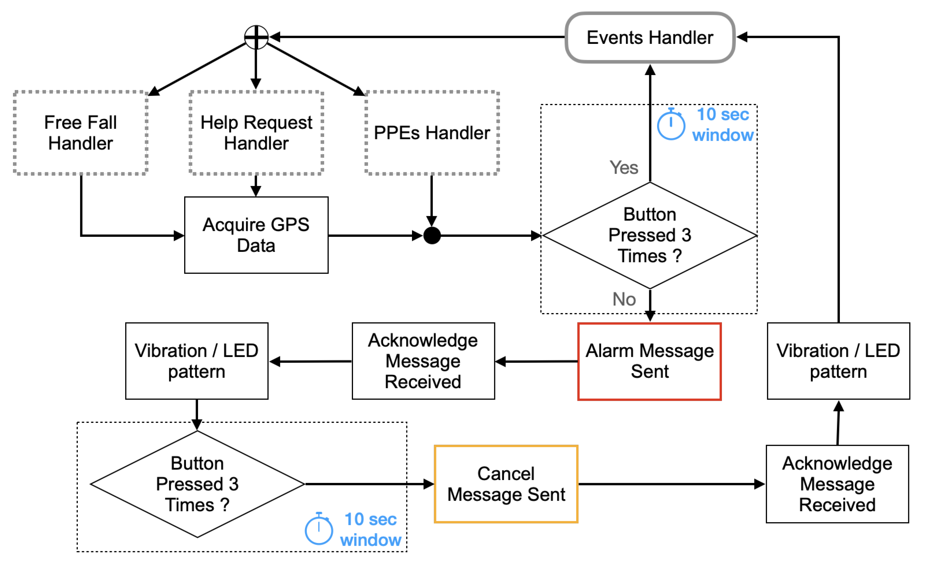
The firmware makes the Small-Devices and the Belt-Devices smart devices. The Small-Devices have a firmware that enables the ANS of a BLE server [36]. The Belt-Device’s firmware, instead, has multiple features, as described in the following. Figure 11 shows the flow chart of the Belt-Device firmware.
In the beginning, since event messages have to be exchanged, an MQTT client deployed on the Belt-Device starts by connecting to the MQTT Broker, i.e., the Edge-Device of the site, and subscribes to the Topics of interest to receive messages from the system.
After this, the flow continues in two parallel paths. The former actuates the device outputs, LED, and vibrator, to produce visual and haptic feedback when a new message is received from the system. The latter evaluates the necessity of publishing an alert whenever an accidental human fall, a button press event is recognized, or a BLE connection is lost.
To verify that the PPE is worn all the time a BLE client, deployed on the Belt Device, associates the initially worn PPE with itself by memorizing the list of BLE servers offering ANS in its proximity.
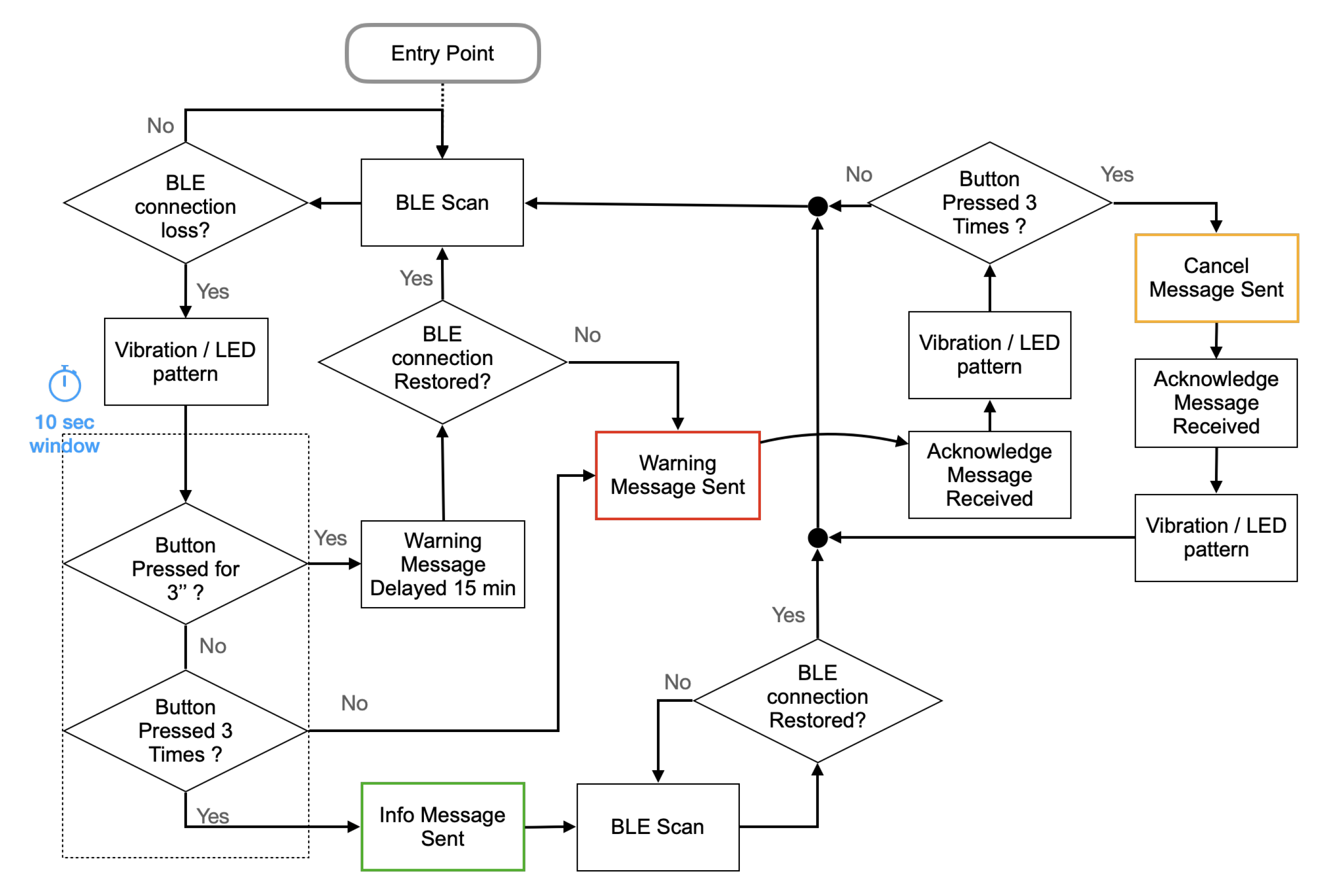
Since the Small-Device embedded in the PPE offers ANS only if the PPE is worn, when any of the BLE server signals is lost, the Belt-Device supposes that the related PPE is not worn or left far from the worker or damaged. In these cases, a warning message to the Edge-Device should be sent, but not immediately. Indeed, a vibrating output is first generated to inform the worker that some PPE is not detected. If the worker presses the button of the Belt-Device one time, for three seconds, before ten seconds expire, the message will be delayed for fifteen minutes or canceled if the BLE signal is restored after this period. This strategy allows the worker to take any PPE off for a limited time without warning the supervisor. If, after vibration, the worker presses the button three times, the warning message will be substituted by an info message, and the procedure restored after the BLE signal has been detected again. This strategy allows the worker to dismiss the PPE voluntarily, for example, during lunchtime or at the end of shift, and at the same time taking note of this kind of event for further analysis (Figure 12).
To detect the free-fall, the accelerometer chip uses an embedded algorithm. It raises an interrupt when the acceleration on the three axes has a pattern compatible with a free-fall [37]. Whenever the MCU detects the free-fall interrupt, it informs the worker by generating a long vibration. If the worker does not cancel the event by keeping the user button pressed for three seconds within 10 s from the haptic feedback, the Belt-Device publishes an alarm message containing the GPS coordinates, so that the rescuers can be notified of the event and the place (Figure 13).
The worker always has the opportunity to cancel the alarm before it is sent or soon after.
To interact with the worker the firmware of the Belt-Device manages the push button, the vibrating device, and the tricolor LED.
In particular:
- To call for help and rescue the worker can press the button of the Belt-Device. When the Button Press Event is detected, the firmware verifies that the button is kept pressed for at least three seconds before publishing an Emergency message to the Edge-Device. This precaution prevents the raising of alarms due to involuntary temporary button press.
- To cancel a false alarm the worker can press the button of the Belt-Device after receiving from the Edge-Device the acknowledgment that the previously published alarm message has been received. The acknowledgment is communicated to the worker by actuating the vibrating device of the Belt-Device for three seconds. If the worker presses the Belt-Device button within ten seconds, a new message from the Belt-Device to the Edge-Device will abort the Emergency condition (Figure 14).
To locate the worker for a fast rescue through GPS, the location is communicated by the Belt-Device after that a free-fall or a help request event has been confirmed. The GPS module outputs the worker’s position, with an NMEA standard string [38]. The NMEA standard is a set of formatted lines, named sentences, easily readable by the MCU serial port. As an example, a sentence can contain the following information:
- Time: 235317.000 is 23:53 and 17.000 s in Greenwich Mean Time.
- Longitude: 4003.9040 N is latitude in degrees.decimal minutes, North.
- Latitude: 10512.5792 W is longitude in degrees.decimal minutes, West.
- Number of satellites seen: 08.
- Altitude: 1577 m.
By processing it, the MCU can extract Time, Longitude, Latitude, and Altitude, and adds them to the Emergency message. It is worth noting that the workers’ position is communicated to the Edge-Device only in these cases, preserving their privacy otherwise.
Although the rescue time depends on many external factors, such as the distance of rescuers from the place of accident or the difficulties in reaching the accident place due to factors such as weather or terrain conditions, a prompt alert of accident occurrence and precise knowledge of the place to reach, undoubtedly accelerate the rescue. This faster reaction can result in life-saving. For example, a Suspension Trauma resulting from a free-fall can occur in as little as 20–30 min, and sometimes less, depending on a person’s health and the nature of injuries sustained in the fall. Rescue needs to begin immediately, as also stated in [39].
4.4.4. The Web Application
The Web application can visualize the workers’ status and possible alarms in real-time. Any mobile or fix device with a modern browser can access a web dashboard and get the workers’ real-time status. Figure 15 shows a schematic view of the whole system and how its software applications communicate.
The web interface uses a multi coordinate view paradigm, where the state of each worker is summarized as a simple list. In case it becomes critical, it is geo-localized and synchronized on a map, as shown in Figure 16.
The connection between the mobile devices and the Apache2 web server uses the SSL protocol to guarantee the security and privacy of exchanged information, even if on a local area network.
4.4.5. Microservices
Microservices realize business logic and back-end operations. In the proposed solution, each MQTT message published is an event. Thus, some events activate some actions while some other events need only to be displayed or notified.
Since the Microservices can publish and subscribe to the Topics on the same MQTT Broker used by the Web application and the Belt-Devices, they can analyze all the published messages and react accordingly. In this way, the events that need to be visualized or notified to the supervisors are directly managed by the MQTT broker, which pushes them directly to the Web page on the connected browsers through websockets. Instead, the Microservices manage the events that require actions. They publish an acknowledgment for each received event as Rescue request, Free-fall revealed (Emergency messages type), PPE dismissed (Alert messages type), Alarm canceled. Furthermore, the Microservices can activate an output signal on the Edge-Device GPIO to actuate an audio alarm if one of the Emergency message types is published. Optionally, the Microservices can persistently log all the events on to Cloud storage for further analysis.
4.4.6. Security Essentials
The Web application utilizing the HTTPS protocol, offers native privacy protection for all the communications between the mobile devices and the Edge-Device.
For the communications between the wearable Belt-Devices and Edge-Device, the proposed solution leverages the MQTT protocol’s security features, offering solutions on three levels:
- At Network level, the data between Belt-Devices and Edge-Device is exchanged on a local Wi-Fi area network. Thus, all the Wi-Fi security protocols are used to prevent the man in the middle attack. The connection with the Cloud resource, if applied, can occur through a VPN connection for additional security, when required.
- At Transport level, TLS/SSL is used for encryption. This method ensures that data cannot be read during transmission and provides client certificate authentication to verify the identity of both parties.
- At Application Level, the MQTT protocol provides client identification and username/password credentials to authenticate devices.
5. Running the Monitoring System
This section briefly illustrates the proposed solution deployed at an outdoor construction site.
Any working site has a site office, where power is available, and an Edge-Device can be deployed. Then, one (or more) access point creates a wireless local area network (WLAN) covering all the site area. If only one access point is enough, it can be in the office and be powered by the site power supply. If the Wi-Fi extension needs to cover a larger area, the extenders can be powered by a battery and solar panel and placed on movable poles. However, the power is usually distributed around the site for illumination requirements or electric-powered tools, so the Wi-Fi extenders could also be powered by those sources.
When a team of workers reaches the construction site, they should put their smart PPE on and wear any of the charged Belt-Devices taken from the charging dock stations.
Before starting to work, the worker initializes the Belt-Device by pressing its button. The initialization consists of the discovery phase, performed by the Belt-Device. In this phase, the Belt-Device looks for the closest BLE servers, offering ANS, and registers these servers as the PPE to monitor. During this phase, a given distance among workers should be respected to avoid that the Belt-Device of one worker could reveal the PPE of another worker and erroneously identify as its one. This problem could be mitigated by letting the initialization phase begin while workers cross a turnstile or a gate one by one.
From that moment on, the Belt-Device can send a message to the Edge-Device in case of loss of PPE. Instead, if a rescue is required by workers or an automatic human fall is detected, and only in these cases, the message also will contain the GPS coordinates of the worker’s position.
As previously described, when messages reach the Edge-Device, they can be read by any client connected to the Web server, and a browser can easily monitor the worker’s state. Whenever an Emergency type message is generated, the Microservices on the Edge-Device will push a notification to the connected Browsers and activate a loud audio alarm to alert the personnel.
Bridging the local MQTT Broker with another remote MQTT Broker on the Cloud allows all the same features remotely.
6. Discussion and Conclusions
The current literature on workers’ safety suggests that the evolution of PPE in smart PPE is an intelligent protection for the future. Although various research papers recommend solutions to improve the safety through electronics and wireless sensors, as recalled in Section 2, it has been noted that there is a lack of proposals specifically targeted to Lone Workers. Employees working in isolation need additional features because they have no one nearby to call for help in the event of an accident. In this paper, a work-in progress research is described in terms of an architecture design offering the following advantages, valid for any worker but beneficial for Lone Workers:
- it verifies the continuous use of smart PPE during the work shift;
- it automatically detects an accidental human fall and calls the rescue without the intervention of the injured person;
- it accelerates the rescue when an accident occurs or a help request is performed.
While it is possible to find other research works that separately offer solutions with this capability, the present work states the following main advantages, currently not available in literature.
- The solution is complete and addresses all the primary requirements, especially crucial for Lone Workers, as the localization, the verification of continuous use of PPE, and the possibility to be in contact with remote workers to seek help.
- The solution is based on the Fog-Computing architecture, offering autonomy from the unreliable and costly Internet connection for all the essential features.
- The solution is simple to deploy, even at large and temporary work sites. It has reduced recurring maintenance costs and guarantees the workers’ privacy while having little impact on the usual activities.
6.1. In-Lab Test Conclusions
Since the network connection appears to be a critical component of the entire proposed solution, its architecture was evaluated in the LabGis laboratory of the University of Salerno. The details of the tests are reported in Appendix A.
The tests results show that the proposed Fog-Computing architecture offers a wide margin of tolerance to the network capacity. Hence, even if the WLAN usage in the proposed solution is not intensive since the communications occur only during exceptional, hopefullly rare, events, during the most stressful test the system was able to manage up to ≈9 alert messages per second, which is a capacity much higher than the necessary expected into an actual deployment.
Although the Internet connection is optionally utilized in the solution, it is not essential due to the proposed Fog-Computing architecture, and the entire solution is tolerant by design to the unreliable Internet connection, as detailed in the paper. For these reasons, it has not been tested.
6.2. Distinctive Technical Features
The proposed hardware was designed to easily transform classic PPE such as helmets, protective gloves, and shoes into smart PPE.
The solution does not require any particular infrastructure, the Wi-Fi coverage of the working site is sufficient. It is also possible to add low-cost Wi-Fi expanders for large worksites when a single Wi-Fi access point is not enough.
The choice of the MQTT protocol for messaging, was revealed to be ideal for connecting low-cost wireless devices with a small code footprint and minimal network bandwidth.
To monitor workers’ status and manage the system, a responsive Web application at the front-end allows the use of smartphones, tablets, and notebooks in the field without installing additional software.
6.2.1. Sensors Scalability
Although in this proposal, only a free-fall detector has been installed on the Belt-Device, the ESP32 module used in the hardware circuit has plenty of interfaces to connect more sensors. For example, in [18], an additional temperature and humidity sensor has been experimented with the same ESP32 electronic module to detect a Firefighter’s exposure to heat. More sensors with I2C, single wire, or simply TTL serial communication can be added with very few adjustments to the firmware and the hardware of the Belt-Device. The application of dangerous gas sensors and gamma ray detectors will be evaluated for other specific workers.
6.2.2. Low-Cost Solution
To design a low-cost solution was one of the most critical factors to make it acceptable to the employers. In this paper, the improvement of the cost/benefit relation is based on the following features:
- the electronic components, which are readily available on the shelf, thus making the costs of the electronics part of smart PPE affordable and the cost of the Edge-Device negligible;
- the installation costs, which could be limited to some additional Wi-Fi expander installation for the large work sites;
- the low recurring costs for maintenance and ownership, which consist of battery changes of the Small-Devices, limited to once every few years, due to BLE technology.
Author Contributions
Conceptualization, P.B. and M.S.; methodology, P.B.; software, P.B.; validation, P.B. and G.V.; investigation, P.B., M.S. and G.V.; resources, P.B. All authors have read and agreed to the published version of the manuscript.
Funding
This research was funded by Regione Campania P.O.R. FSE 2014/2020 grant number 300392FDR18DELUCIA.
Acknowledgments
The authors would like to thank Allinit S.r.L. for making the equipment available and for their contribution in hardware design.
Conflicts of Interest
The authors declare no conflict of interest.
Abbreviations
The following abbreviations are used in this manuscript:
| ANS | Alert Notification Services of BLE protocol |
| BLE | Bluetooth Low Energy |
| EEC | European Economic Community |
| Fog-Computing | A specific architecture of Edge-Computing |
| GPIO | General Purpose Input/Output Ports |
| GPS | Global Positioning System |
| HTTP | Hypertext Transfer Protocol |
| HTTPS | Hypertext Transfer Protocol Secure |
| IoT | Internet of Things |
| LabGIS | Laboratory of Geographic Information Systems (University of Salerno) |
| LAMP | Linux, Apache, MySql, PHP |
| LAN | Local Area Network |
| LED | Light-emitting diode |
| ML | Machine Learning |
| MQTT | Message Queuing Telemetry Transport |
| OASIS | Organization for the Advancement of Structured Information Standards |
| OSH | European Occupational Health and Safety |
| PAN | Personal Area Network |
| PPE | Personal Protective Equipment. AKA helmets, gloves, shoes |
| QoS | Quality of Service |
| RFID | Radio-frequency Identification |
| Smart PPE | PPE with electronics |
| SMS | Short Message Service |
| SSL | Secure Sockets Layer |
| TCP | Transmission Control Protocol |
| TLS | Transport Layer Security Protocol |
| TTL | A serial signaling standard based on a transistor–transistor logic interface |
| WAN | Wide Area Network |
| Wi-Fi | A family of wireless network protocols, based on the IEEE 802.11 |
| WLAN | Wireless Local Area Network |
Appendix A. Description of the In-Lab Tests
The proposed architecture was tested in the LabGis at the University of Salerno. Since the network plays a relevant role in the proposed solution, some tests were performed to evaluate the capability of the designed distributed architecture and validate its adequacy concerning the intended purposes.
For the tests, following the diagram in the Figure 15, messages were generated between the involved nodes.
In the end, an evaluation of the resulting message exchange capacity against the needs of the proposed solution was performed.
Appendix A.1. Materials for the Tests
The system under test was made up of the following hardware:
- One Access Point (AP) TP-Link TL-MR3040.
- One Belt-Device prototype.
- Five Small-Devices to embed on two PPEs.
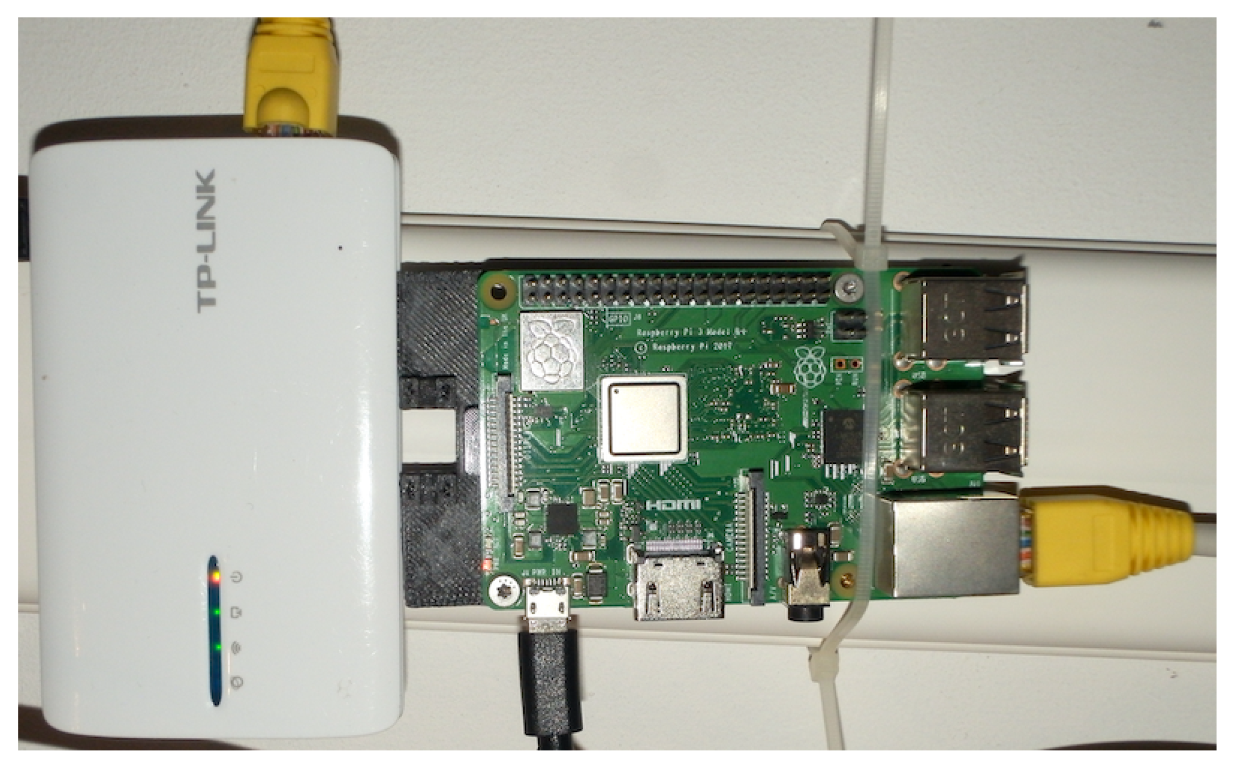
During the test setup, the fixed IP address 10.10.1.215 was assigned to the Edge-Device, which represented the IP address of the Web application as well the address of the local MQTT broker on the LAN. The AP was assigned the Service Set Identifier (SSID) and authentication credentials to access the WLAN with a Wi-Fi Protected Access II (WPA2).
On the Edge-Device the so-called LAMP configuration was installed, consisting of the last stable version of an Apache2 web-server with PHP module and the MySQL database management system.
Figure A1.
Edge-Device configuration.

A Mosquitto MQTT broker was installed on the Edge-Device, configured with two listeners, one on the default port with MQTT protocol and another on a different port with websockets protocol.
The Belt-Device application, as previously explained, was developed by using the Lua computer language. Lua is a lightweight, embeddable scripting language. Since the micro-controller of the Belt-Device was an ESP32 SoC module, the environment was deployed by using the NodeMCU [40] firmware, an open-source eLua based firmware layered on the Espressif® NON-OS SDK [41]. To edit and load the application on the Belt-Device the ESPlorer was used— Integrated Development Environment (IDE) for ESP8266 developers [42].
The features of the Small-Device described in Section 4 were developed by using the Nordic® SoftDevices for communication and the nRF52 SDK13.0 for development. SoftDevices are pre-compiled, event-driven protocol stacks with APIs that allow the application to clearly interact with the BLE protocol. Nordic® developed, tested, and maintains SoftDevices.
Appendix A.2. Evaluation of the Communication Capacity
Defined the capacity of communication as the number of messages that through the network it is possible to display on a web page in one second, the test was designed to measure the capacity of the proposed system in displaying on the supervisor web page the messages published by the Belt-Devices.
Appendix A.2.1. Methods
A test web page was loaded by a browser on a PC connected to the WLAN. When the page was loaded, the JavaScript code published the PC clock current time to a specific MQTT Topic. The Belt-Device received the message and fixed its internal real-time clock. This operation synchronized the two clocks in almost real-time, within a precision of many orders smaller than one second, which is the resolution required for the tests. Since the JavaScript code of the web page subscribed to the topic ‘test’ with a web sockets connection, each message published on this topic was then shown on the web page in real-time.
Initially, a simple loop on Belt-Device published 2000 messages, which were displayed on the web page, to measure the overall capacity of Belt-Device in the publication of messages. The measurements showed that the page was able to display 182 messages per second (Figure A2a).
This capacity is referred to, in this experiment, as the channel capacity; it is the estimated maximum quantity of messages per second that the system architecture eventually can display to the supervisors of lone workers.
Since the longer network path involves the Small-Device, the Belt-Device, the Edge-Device up to the browser of the supervisor, further tests were done as follows. To evaluate the publishing capacity of the Belt-Device while detecting the Small-Devices in the proximity, one Small-Device was turned on, and the Belt-Device forwarded its MAC address to MQTT Broker as soon as it detects the Small-Device BLE advertise (ADV). The Small-Device was set to transmit an ADV each 100 ms, while the Belt-Device BLE discovery cycle was set to wait for the ADV for 12.5 ms each 25 ms.
The measurements showed that the page was able to display 100 received messages in 33 s, it is ≈3 messages each second.
Given as a delay where are the seconds elapsed from the Unix epoch (00:00:00 UTC on 1 January 1970) to the Belt-Device BLE ADV detection, and are the seconds elapsed from the Unix epoch to the message visualization on the web page, out of 100 received messages, 61 of them showed a delay D of 1 s, while the remaining 39 messages showed a delay , thus giving an average delay of 0.61 s (Figure A2b).
Figure A2.
Screenshot of Web pages during the tests.

Appendix A.2.2. Conclusions
The tests were repeated several times. None of the sent messages was lost, and the timing was stable as reported. These results were expected, considering the well-controlled environment of the laboratory. Although more tests should be done on fields where the environment could affect network stability, the following observation must be considered. The Belt-Device publishes messages only in the event that a smart PPE is dismissed, or an accidental worker falls, or a worker calls for help. All these events are expected to have a shallow frequency, almost very rare, while the measured communication capacity of the whole system is many orders higher, even considering some connection problem that would oblige the Belt-Device to resend the message multiple times. This consideration makes us confident about the proposed architecture. Likewise, in the unlikely case of a large number of events simultaneously, for example, if 100 lone workers require rescue concurrently, the tests showed that this eventuality is still within the channel capacity.
Furthermore, it is worth noting that even a delay of one second from the event and the reception of its message on the supervising system would not invalidate the advantage of the proposed solution.
Appendix A.3. Stress Tests on BLE Proximity Detection
Appendix A.3.1. Methods
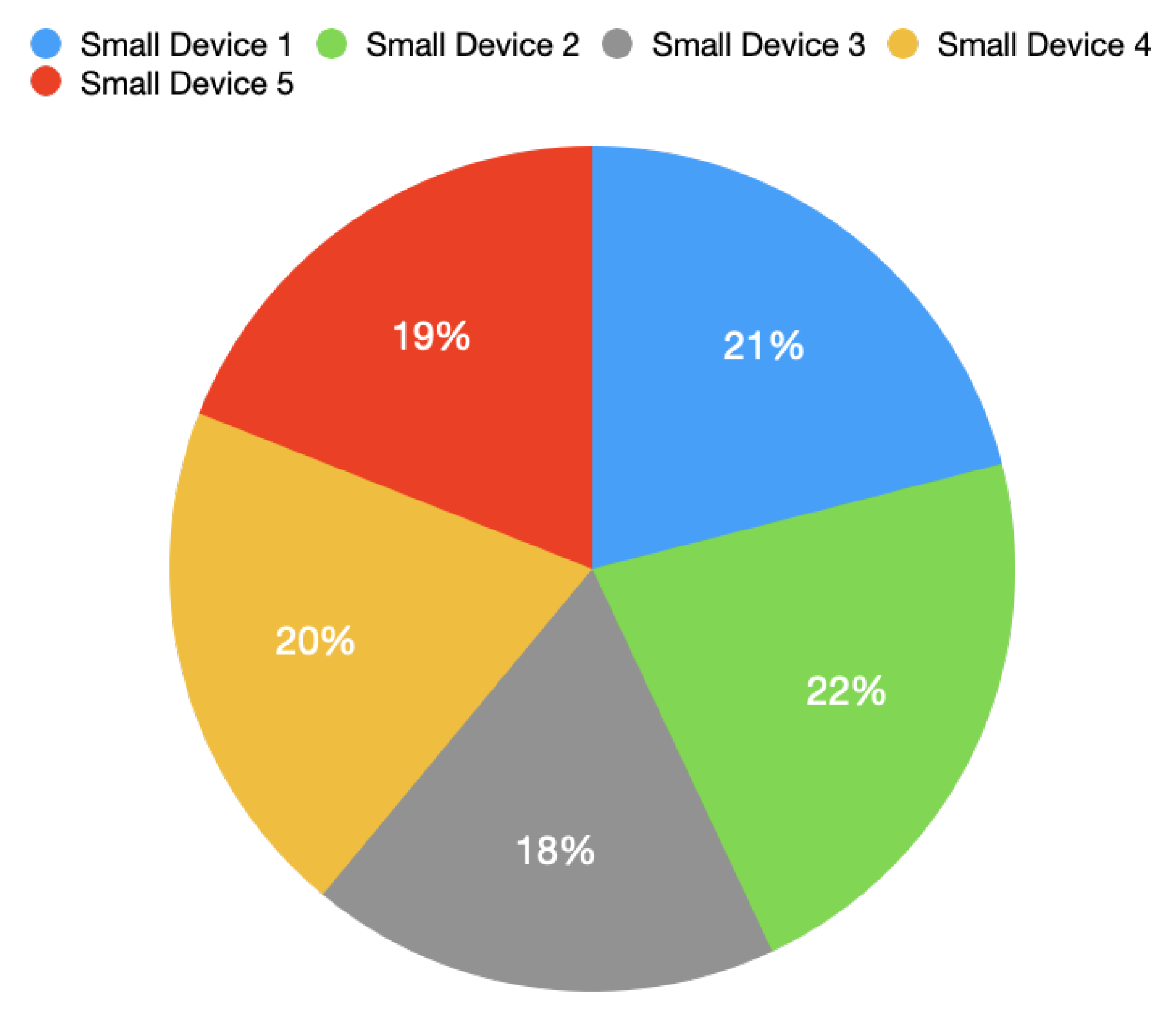
The previous test was repeated with five Small-Devices detected by the same Belt-Device, to validate the hypothesis that a more significant number of Small-Devices in the proximity of one Belt-Device will not exceed the channel capacity.
Appendix A.3.2. Conclusions
The measurements showed that the page was able to display 100 messages in 11 s, it is ≈9 received messages each second. Considering that only multiples of seconds were measured, out of 100 received messages, 85 of them had a delay s, while the remaining 15 messages measured a delay , giving an average delay of ≈0.86 s. The following graph, Figure A3, shows the distribution of messages among the five Small-Devices, displayed by the web page in 11 s.
Figure A3.
Messages distribution among the Small-Devices.

Even with five Small-Devices simultaneously monitored, the Belt-Device is able to communicate their connections to the Edge-Device, continuously and almost uniformly, occupying still a small part of the channel capacity.
References
- European Union’s Occupational Safety and Health. OSH in General. Available online: https://oshwiki.eu/wiki/OSH_in_general#Costs_of_work_accidents_and_occupational_diseases (accessed on 14 December 2020).
- European Agency for Safety and Healt at Work. Directive 89/656/EEC-Use of Personal Protective Equipment. Available online: https://osha.europa.eu/en/legislation/directives/4 (accessed on 14 December 2020).
- Kimberly-Clark Professional. Alarming Number of Workers Fail to Wear Required Protective Equipment. Available online: https://investor.kimberly-clark.com/news-releases/news-release-details/alarming-number-workers-fail-wear-required-protective-equipment (accessed on 14 December 2020).
- European Agency for Safety and Health at Work. Smart Personal Protective Equipment: Intelligent Protection for the Future. Available online: https://osha.europa.eu/en/publications/smart-personal-protective-equipment-intelligent-protection-future/view (accessed on 25 May 2021).
- Shabina, S. Smart Helmet Using RF and WSN Technology for Underground Mines Safety. In Proceedings of the 2014 International Conference on Intelligent Computing Applications, Coimbatore, India, 6–7 March 2014; pp. 305–309. [Google Scholar] [CrossRef]
- Kanan, R.; Elhassan, O.; Bensalem, R.; Husein, A. A wireless safety detection sensor system. In Proceedings of the 2016 IEEE SENSORS, Orlando, FL, USA, 30 October–3 November 2016; pp. 1–3. [Google Scholar] [CrossRef]
- Li, H. Research on safety monitoring system of workers in dangerous operation area of port. In Proceedings of the 2017 4th International Conference on Transportation Information and Safety (ICTIS), Alberta, Canada, 8–10 August 2017; pp. 400–408. [Google Scholar] [CrossRef]
- Cho, C.; Park, J. An Embedded Sensory System for Worker Safety: Prototype Development and Evaluation. Sensors 2018, 18, 1200. [Google Scholar] [CrossRef] [PubMed] [Green Version]
- Jeong, M.; Lee, H.; Bae, M.; Shin, D.; Lim, S.; Lee, K.B. Development and Application of the Smart Helmet for Disaster and Safety. In Proceedings of the 2018 International Conference on Information and Communication Technology Convergence (ICTC), Jeju Island, Korea, 17–19 October 2018; pp. 1084–1089. [Google Scholar] [CrossRef]
- Faramondi, L.; Bragatto, P.; Fioravanti, C.; Gnoni, M.G.; Guarino, S.; Setola, R. A Wearable Platform to Identify Workers Unsafety Situations. In Proceedings of the 2019 II Workshop on Metrology for Industry 4.0 and IoT (MetroInd4.0 IoT), Naples, Italy, 4–6 June 2019; pp. 339–343. [Google Scholar] [CrossRef]
- Wu, F.; Wu, T.; Yuce, M.R. Design and Implementation of a Wearable Sensor Network System for IoT-Connected Safety and Health Applications. In Proceedings of the 2019 IEEE 5th World Forum on Internet of Things (WF-IoT), Limerick, Ireland, 15–18 April 2019; pp. 87–90. [Google Scholar] [CrossRef]
- Luo, W.; Wang, Q. Hardhat-Wearing Detection with Cloud-Edge Collaboration in Power Internet-of-Things. In Proceedings of the 2019 4th International Conference on Mechanical, Control and Computer Engineering (ICMCCE), Hohhot, China, 24–26 October 2019; pp. 681–6813. [Google Scholar] [CrossRef]
- Long, X.; Cui, W.; Zheng, Z. Safety Helmet Wearing Detection Based On Deep Learning. In Proceedings of the 2019 IEEE 3rd Information Technology, Networking, Article and Automation Control Conference (ITNEC), Chengdu, China, 15–17 March 2019; pp. 2495–2499. [Google Scholar] [CrossRef]
- Ravikiran, M.; Sen, S. Improving Industrial Safety Gear Detection through Re-ID conditioned Detector. In Proceedings of the 2019 IEEE Applied Imagery Pattern Recognition Workshop (AIPR), Washington, DC, USA, 15–17 October 2019; pp. 1–10. [Google Scholar] [CrossRef]
- Mehata, K.M.; Shankar, S.K.; Karthikeyan, N.; Nandhinee, K.; Hedwig, P.R. IoT Based Safety and Health Monitoring for Construction Workers. In Proceedings of the 2019 1st International Conference on Innovations in Information and Communication Technology (ICIICT), Chennai, India, 25–26 April 2019; pp. 1–7. [Google Scholar] [CrossRef]
- Park, M.; Park, S.; Song, M.; Park, S. IoT-based Safety Recognition Service for Construction Site. In Proceedings of the 2019 Eleventh International Conference on Ubiquitous and Future Networks (ICUFN), Zagreb, Croatia, 2–5 July 2019; pp. 738–741. [Google Scholar] [CrossRef]
- Jayasree, V.; Kumari, M.N. IOT Based Smart Helmet for Construction Workers. In Proceedings of the 2020 7th International Conference on Smart Structures and Systems (ICSSS), Chennai, India, 23–24 July 2020; pp. 1–5. [Google Scholar] [CrossRef]
- Battistoni, P.; Di Gregorio, M.; Giordano, D.; Sebillo, M.; Tortora, G.; Vitiello, G. Wearable Interfaces and Advanced Sensors to Enhance Firefighters Safety in Forest Fires. In Proceedings of the International Conference on Advanced Visual Interfaces, AVI ’20, Salerno, Italy, 28 September–2 October 2020; Association for Computing Machinery: New York, NY, USA, 2020. [Google Scholar] [CrossRef]
- Shi, W.; Cao, J.; Zhang, Q.; Li, Y.; Xu, L. Edge Computing: Vision and Challenges. IEEE Int. Things J. 2016, 3, 637–646. [Google Scholar] [CrossRef]
- Cisco. Cisco Annual Internet Report (2018–2023) White Paper. Available online: https://www.cisco.com/c/en/us/solutions/collateral/executive-perspectives/annual-internet-report/white-paper-c11-741490.html (accessed on 16 December 2020).
- Yousefpour, A.; Ishigaki, G.; Jue, J.P. Fog Computing: Towards Minimizing Delay in the Internet of Things. In Proceedings of the 2017 IEEE International Conference on Edge Computing (EDGE), Honolulu, HI, USA, 25–30 June 2017; pp. 17–24. [Google Scholar]
- Iorga, M.; Feldman, L.; Barton, R.; Martin, M.J.; Goren, N.S.; Mahmoudi, C. Fog Computing Conceptual Model. NIST Pubs 500–325, National Istitute of Standards and Techology. 2018; Techreport. Available online: https://nvlpubs.nist.gov/nistpubs/SpecialPublications/NIST.SP.500-325.pdf (accessed on 31 May 2021).
- Battistoni, P.; Sebillo, M.; Vitiello, G. Computation Offloading with MQTT Protocol on a Fog-Mist Computing Framework; Number 11874 in Lecture Notes in Computer Science (including subseries Lecture Notes in Artificial Intelligence and Lecture Notes in Bioinformatics); Springer: Cham, Switzerland, 2019. [Google Scholar]
- Battistoni, P.; Sebillo, M.; Vitiello, G. Experimenting with a Fog-Computing Architecture for Indoor Navigation. In Proceedings of the 2019 Fourth International Conference on Fog and Mobile Edge Computing (FMEC), Rome, Italy, 10–13 June 2019; pp. 161–165. [Google Scholar] [CrossRef]
- Banks, A.; Briggs, E.; Borgendale, K.; Gupta, R. MQTT Version 5.0. Available online: https://docs.oasis-open.org/mqtt/mqtt/v5.0/mqtt-v5.0.html (accessed on 25 November 2020).
- Jacobsen, H.A. Publish/Subscribe. In Encyclopedia of Database Systems; Springer: New York, NY, USA, 2009; pp. 2208–2211. [Google Scholar]
- Light, R.A. Mosquitto: Server and client implementation of the MQTT protocol. J. Open Source Softw. 2017, 2, 265. [Google Scholar] [CrossRef]
- Nordic Semiconductor. The nRF52 Series Multiprotocol SoCs. Available online: https://www.nordicsemi.com/Products/Low-power-short-range-wireless/Bluetooth-5 (accessed on 30 November 2020).
- Espressif. A Feature-Rich MCU with Integrated Wi-Fi and Bluetooth. Available online: https://www.espressif.com/en/products/socs/esp32 (accessed on 30 November 2020).
- Analog Devices. 3-Axis Digital Accelerometer. Available online: https://www.analog.com/media/en/technical-documentation/data-sheets/ADXL345.pdf (accessed on 30 November 2020).
- Quectel. GNSS Module with Chip Antenna. Available online: https://www.quectel.com/product/l96.htm (accessed on 30 November 2020).
- Hillar, G.C. MQTT Essentials: A Lightweight IoT Protocol: The Preferred IoT Publish-Subscribe Lightweight Messaging Protocol; Packt Publishing: Birmingham, UK, 2017. [Google Scholar]
- Internet Engineering Task Force. The WebSocket Protocol. Available online: https://tools.ietf.org/html/rfc6455 (accessed on 30 November 2020).
- Lee, S.; Kim, H.; Hong, D.k.; Ju, H. Correlation analysis of MQTT loss and delay according to QoS level. In Proceedings of the The International Conference on Information Networking 2013 (ICOIN), Bangkok, Thailand, 28–30 January 2013; pp. 714–717. [Google Scholar] [CrossRef]
- Bluetooth SIG. Core Specification. Available online: https://www.bluetooth.com/specifications/bluetooth-core-specification/ (accessed on 24 November 2020).
- Bluetooth SIG. Alert Notification Service. Available online: https://www.bluetooth.com/specifications/gatt/ (accessed on 24 November 2020).
- Jia, N. Detecting Human Falls with a 3-Axis Digital Accelerometer. Available online: https://www.analog.com/en/analog-dialogue/articles/detecting-falls-3-axis-digital-accelerometer.html (accessed on 10 December 2020).
- Gakstatter, E. What Exactly Is GPS NMEA Data? Available online: https://www.gpsworld.com/what-exactly-is-gps-nmea-data/ (accessed on 2 December 2020).
- U.S. Department of Labor. Suspension Trauma/Orthostatic Intolerance. Available online: https://www.osha.gov/sites/default/files/publications/shib032404.pdf (accessed on 23 June 2021).
- Overview-NodeMCU Documentation. Available online: https://nodemcu.readthedocs.io/en/dev-esp32/ (accessed on 18 July 2021).
- ESP8266 Non-OS SDK API References. Available online: https://www.espressif.com/sites/default/files/documentation/2c-esp8266_non_os_sdk_api_reference_en.pdf (accessed on 18 July 2021).
- ESPlorer. Available online: https://esp8266.ru/esplorer/ (accessed on 18 July 2021).
Figure 1.
A proposal to classify a smart PPE, according to composition and data collection capabilities, as described in [4].
Figure 1.
A proposal to classify a smart PPE, according to composition and data collection capabilities, as described in [4].

Figure 2.
An Edge-Computing architecture.

Figure 3.
Publishers and subscribers, examples without and with wildcard.

Figure 4.
An MQTT Brokers bridge.

Figure 5.
The Fog-Computing architecture.

Figure 6.
A personal area network.

Figure 7.
Small-Device prototype.

Figure 8.
A Belt-Device schema.

Figure 9.
Belt-Device prototype.

Figure 10.
Networking.

Figure 11.
Belt-Device firmware flowchart.

Figure 12.
PPE worn check, flowchart.

Figure 13.
Free-fall check.

Figure 14.
False alarm cancellation flowchart.

Figure 15.
System software overview.

Figure 16.
The Web application screenshot.

Publisher’s Note: MDPI stays neutral with regard to jurisdictional claims in published maps and institutional affiliations. |
© 2021 by the authors. Licensee MDPI, Basel, Switzerland. This article is an open access article distributed under the terms and conditions of the Creative Commons Attribution (CC BY) license (https://creativecommons.org/licenses/by/4.0/).
Share and Cite
MDPI and ACS Style
Battistoni, P.; Sebillo, M.; Vitiello, G. An IoT-Based Mobile System for Safety Monitoring of Lone Workers. IoT 2021, 2, 476-497. https://0-doi-org.brum.beds.ac.uk/10.3390/iot2030024
AMA Style
Battistoni P, Sebillo M, Vitiello G. An IoT-Based Mobile System for Safety Monitoring of Lone Workers. IoT. 2021; 2(3):476-497. https://0-doi-org.brum.beds.ac.uk/10.3390/iot2030024
Chicago/Turabian StyleBattistoni, Pietro, Monica Sebillo, and Giuliana Vitiello. 2021. "An IoT-Based Mobile System for Safety Monitoring of Lone Workers" IoT 2, no. 3: 476-497. https://0-doi-org.brum.beds.ac.uk/10.3390/iot2030024