Design, Dimensioning and Simulation of Inerters for the Reduction of Vehicle Wheel Vibrations—Case Studies


1
IILS Ingenieurgesellschaft für Intelligente Lösungen und Systeme mbH, 70771 Leinfelden-Echterdingen, Germany
2
Department of Mechanical Engineering, Ravensburg-Weingarten University (RWU), 88250 Weingarten, Germany
3
Design Theory and Similarity Mechanics Group, Institute of Aircraft Design, University of Stuttgart, 70569 Stuttgart, Germany
*
Author to whom correspondence should be addressed.
Vehicles 2020, 2(3), 424-437; https://0-doi-org.brum.beds.ac.uk/10.3390/vehicles2030023
Submission received: 25 May 2020
/
Revised: 16 June 2020
/
Accepted: 28 June 2020
/
Published: 29 June 2020
Abstract
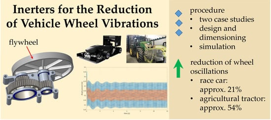
:For the last two decades, a novel mechanical system has received increasing attention—the inerter. An inerter is a system that can store mechanical energy for a rather short amount of time and behaves analogously to a capacitor in electrical engineering. Until today, only a few inerter applications have been reported. In a vehicle suspension, an inerter can be used to reduce wheel vibrations. This paper demonstrates the application potential of the novel mechanical system and describes the design and dimensioning of an inerter for the reduction of these kind of wheel vibrations for two completely different vehicle concepts. The first application concerns a Formula Student race car in which the main objective represents the maximization of the mechanical grip to improve lap times. For the inerter dimensioning in a racing car, lightweight design is a major issue. The second application is an agricultural tractor in which the focus is on the reduction of the ground pressure to protect the environment as well as on a very robust and compact realization of the inerter. A detailed simulation of both cases allows a qualitative and quantitative assessment of the wheel vibration reduction potential. In both applications, a considerable improvement potential could be identified which amounts, in the case of the race car, to a reduction of wheel oscillation of about 21% and for the tractor to a wheel vibration reduction potential of up to 54%.
1. Introduction
The original idea for the novel mechanical system in the focus of this paper, the so-called inerter, was first published by Smith in 2002 [1]. He used the known analogy between electrical and mechanical systems to synthesize a new device he called the inerter. In electrical systems, a capacitor—a system component that can store electrical energy—may be used for smoothing the output of a power supply. Analogously, an inerter is a mechanical system that can store energy, e.g., by means of accelerating a flywheel, and it can be used for decreasing vibrations.
In all kinds of technical systems, mechanical vibrations can lead to negative effects or even catastrophic failures. Therefore, several scientists have intensively researched this novel mechanical system and possible application scenarios. One possible application field is the building industry. For instance, Wang et al. [2] were investigating the suitability of passive vibration control systems for excited building structures employing inerters. Systems objected to earthquake excitations were in the focus of the research work of De Angelis et al. [3] and Radu et al. [4]. The research of Marian and Giaralies [5] concentrated on the vibration control of chain-like structural systems employing inerters, and the research of Sun et al. [6] dealt with cable-stayed bridges. Current developments and investigations, which are not application specific, include inerters which employ a continuous velocity transmission (CVT) for changing the inertance [7], the influence of inerters on the natural frequencies of vibrating systems [8], an inverse screw transmission for the two-terminal manipulation of a flywheel [9], planetary flywheel inerters [10], variable inertia flywheels in power hydraulic systems [11] and tuned mass-damper-inerters for, amongst others things, energy harvesting [12,13].
In the area of ground vehicles, research activities concern the steering compensation for high-performance motorcycles [14]. Several research groups work have worked directly on the suspension systems and investigate adaptive flywheels made of two different materials [15], the improvement of train suspension systems [16], the improvement of passenger comfort, tire grip and suspension deflection [17,18,19]. In vehicles, the most promising application area for inerters is the suspension system. This novel system was first used in a Formula 1 race car in 2005, when the McLaren team applied an inerter for reducing the wheel vibrations at the rear axle [20]. Despite the existing research and first applications, a lack of design and dimensioning guidelines concerning inerters as well as established simulation procedures is still evident. The improvement potential in the area of vehicle suspension needs to be quantified and specific application cases need to be simulated in detail. Such simulations should concentrate on simulation activities concerning vehicles suspensions, for instance, the works that have been carried out so far have been focused on analyzing noise and vibration [21]; these works are therefore more focused in the modification of structural dynamics.
The focus of the research described in this paper concentrates on the design and dimensioning of an inerter for the reduction of wheel vibrations based on a simulation analysis. The simulation study is hereby based on the investigation of two quite different vehicle concepts. Firstly, the design and dimensioning for a Formula Student race car is carried out. In this case, the maximization of the mechanical grip to improve lap time is the essential success criterion. Furthermore, there exists the necessity to integrate the design implementation into the existing vehicle concept, and the chosen design implementation needs to be as light as possible. In the second case, the requirements for agricultural machinery, such as a tractor, are rather different. For a tractor, the reduction of the ground pressure to protect the environment as well as a completely robust and at the same time compact implementation are the main requirements. For both kinds of application cases, a conceptual design and dimensioning activity were carried out and concluded a detailed simulation study.
To summarize, the scientific questions to be answered in this paper are:
- How can an inerter be designed and dimensioned for the reduction of wheel vibrations in a specific vehicle application?
- How can the performance of an inerter for the reduction of wheel vibrations be quantitatively modeled, simulated and qualitatively evaluated?
- To what extent will the wheel vibrations be reduced by means of an inerter and to what extent can lap times be effectively reduced in racing applications?
- To what extent can the maximum soil pressure be reduced by means of an inerter in agricultural applications?
The structure of this paper corresponds to these four scientific questions. The theoretical basis is laid out in Section 2; in this section the underlying physical and mathematical model of the inerter is developed. The details of the inerter simulations are shown and explained in Section 3. The focus of Section 4 is both the inerter application in a race car and an agricultural tractor. The paper closes in Section 5 with the main conclusions and some recommendations for further research.
2. Physical and Mathematical Model
In most vehicles, the wheel is connected to the chassis by a spring and a damper system [22]. In this configuration, the spring produces a force relative to its elongation [23], while the force of the damper is dependent on the velocity in bump and rebound [24]. The spring acts as an elastic element, which allows a relative movement between the wheel and the chassis [25]. In a bump movement the spring and damper absorb the energy, which results from the relative movement between the chassis and the road surface. In rebound, the energy stored in the spring gets dissipated by the damper [26]. The stiffness of the spring influences how much energy can be stored at a given displacement and affects the driving comfort as it limits the relative movement between the wheel and chassis [27]. The main task of the damper is to reduce wheel-load variation and keep the tire contact firm on the ground [27]. In the case where there is no contact between the tire and the road surface, neither longitudinal nor lateral forces can be transferred. The setting of the damper is therefore crucial to improve a vehicle’s driving behavior and level of performance.
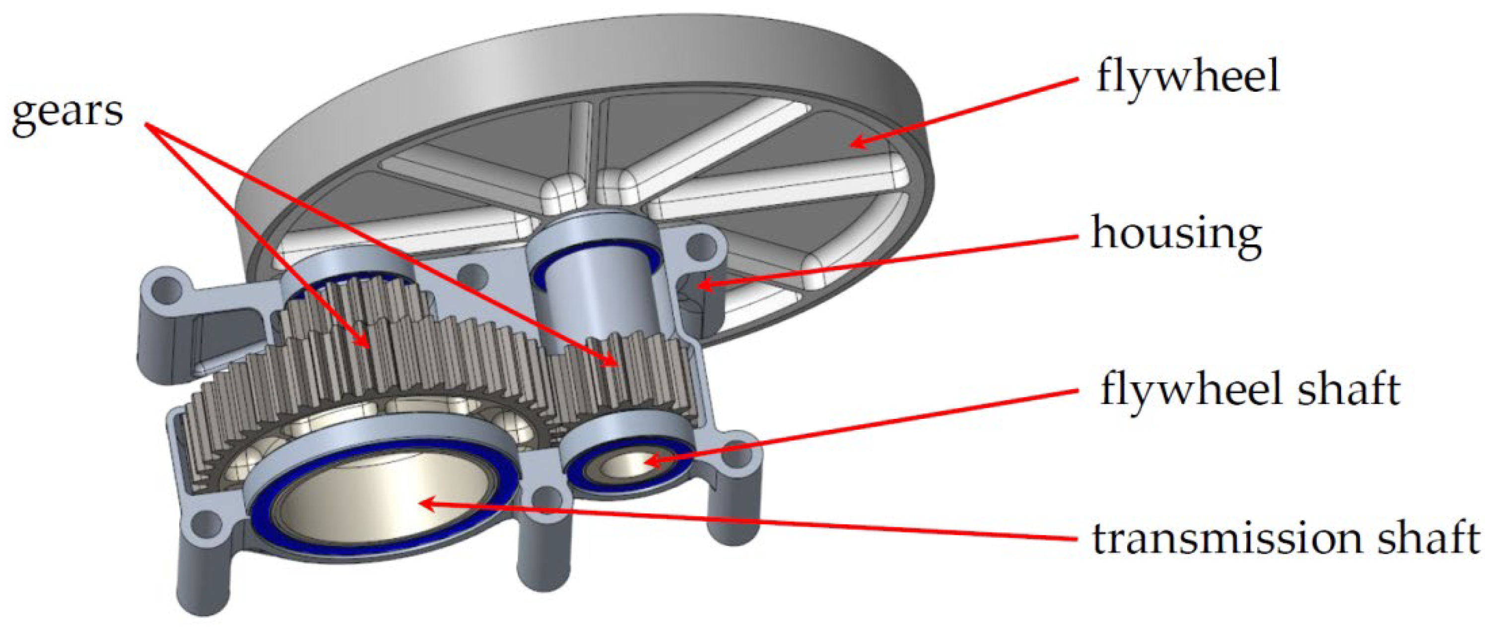
As the spring is sensitive to displacement and the damper to velocity, the idea of the inerter is to act against accelerations. Therefore, the inerter is connected in parallel to the spring and the damper in between the wheel and the chassis. The setting of the inerter itself is quite simple. It consists of a flywheel and a gearbox. The gearbox can be realized in different ways, for example as a combination of a rack and pinion, several gears or a spindle. The final acting moment of inertia of the inerter is dependent on the gear transmission ratio and the moment of inertia of the flywheel itself. A possible design of the inerter is shown in Figure 1.
Similar to the suspension, the tires of a vehicle act as a spring and damper system as well [28]. This is due to the fact that rubber is a visco-elastic material with a behavior which is between the behavior of a viscous liquid and that of an elastic solid. Therefore, on the one hand, the rubber acts as a spring by restoring a force relative to its deformation and on the other hand acts like a damper by dissipating energy as heat. Since the self-damping of a tire is relatively low compared to its stiffness, the tire is able to oscillate. The main task of the inerter is to act against these oscillations coming from the tire and therefore improve the contact between the wheel and the ground [20].
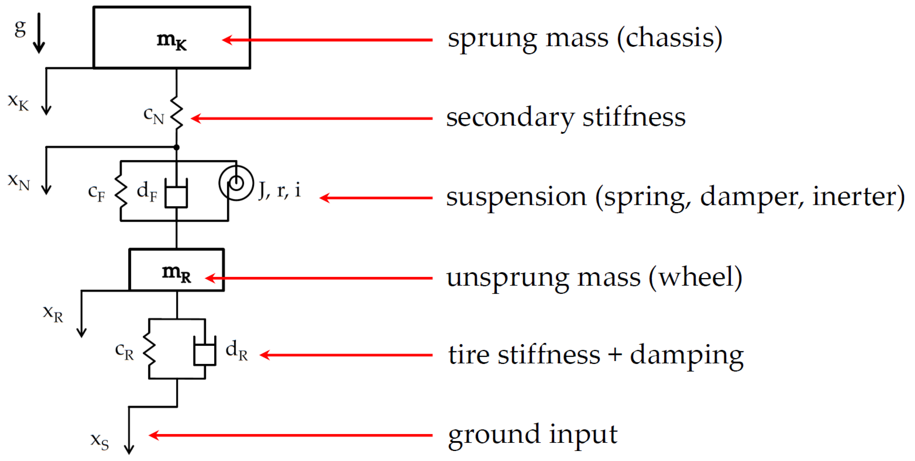
To model the described system, a double mass oscillator [29] is used. In this example, the model is valid for each wheel of the vehicle. The model and equation parameters are illustrated in Figure 2.
Starting from the top, mK is the mass of the chassis for each wheel. The spring cN represents the stiffnesses of the chassis and the suspension parts and is in series connection to the suspension itself. The suspension of the vehicle consists of a spring (cF), a damper (dF) and the inerter (J, r, i), which are connected in parallel. Coupled to the suspension is the unsprung mass (mR), which is connected to the ground via the tire. The tire is modeled as a spring-damper system consisting of a spring (cR) and a damper (dR). The ground (i.e., road surface) is described by the variable xS, which can be either a step function, which is a single deflection, or a periodic excitation in the form of a sine function. The variables xR and xK encode the displacement of the wheel and the chassis, while g is the acceleration due to gravity. Based on the described system above, the following equations have to be solved [29]:
As cN and cF are connected in series, the stiffness of the suspension converges against the stiffness of the spring with the lower spring rate. In order to make the system consisting of the spring (cF), the damper (dF) and the inerter (J, r, i) work properly, the stiffness of cN needs to be higher than the stiffness of cF by a factor of about 1000. In mechanics, a system with this property is called a stiff system [30]. If this is not the case, the amplitude of the undamped oscillation resulting from cN becomes dominant and superposes with the oscillation of the suspension. If this happens, both the amplitude and decay time of the oscillation of the wheel and chassis increase. The example shown in Figure 3 illustrates this correlation.
In this simulation, the input by the road is in the shape of a step function with an amplitude of 100 mm. The system’s eigenfrequency [27] is 4.0 Hz and the attenuation factor [31] is 70%. The stiffness of cN is increased in two steps beginning with cN = 10*cF (blue), cN = 100*cF (red) and cN = 1000*cF (orange). The influence of the stiffness of cN on the amplitude and decay time of the system’s oscillation is obvious. The higher the stiffness of cN, the lower is the influence of the undamped oscillation arising from cN on the suspension, consisting of a spring and damper, and therefore, the amplitude and decay time of the oscillation of the chassis is reduced.
3. Simulation Model
To solve the differential equation system (1), (2) and (3), a model within MATLAB/Simulink (The MathWorks, Inc., Natick, MA, USA) was built. The complete design and optimization process was implemented in this software tool. First, all the relevant constants and variables are integrated within a MATLAB script. Depending on the type of vehicle, the spring stiffnesses and damping ratios are set to a fixed value. Therefore, the variables are the mass moment of inertia of the flywheel (J), the pitch circle radius of the pinion on the shaft of the flywheel (r) and the transmission of the gearbox (i), which is the ratio of the revolution speed of the flywheel and the rotational speed of the wheel around the instantaneous center of rotation, which is given by the vehicle’s suspension kinematics. These three variables result in an effective inerter mass (mI) that produces a force dependent on acceleration [29].
The amount of mI is the relevant optimization parameter. The inertia of the flywheel and the final transmission of the gearbox are design parameters to achieve this final value in the best possible way. Additional limitations may be (for example) a given design space or a weight limit.
To reproduce the input of the road surface to the system, the variable xS is used. A single-wheel bump [32] is initiated by a step function, while the amplitude of the step is freely selectable. Furthermore, the system can be stimulated by a periodic sine function, which simulates the drive on a field or a (damaged) road. The sine function can be adjusted to different load cases by the speed of the car and the amplitude of the wave.
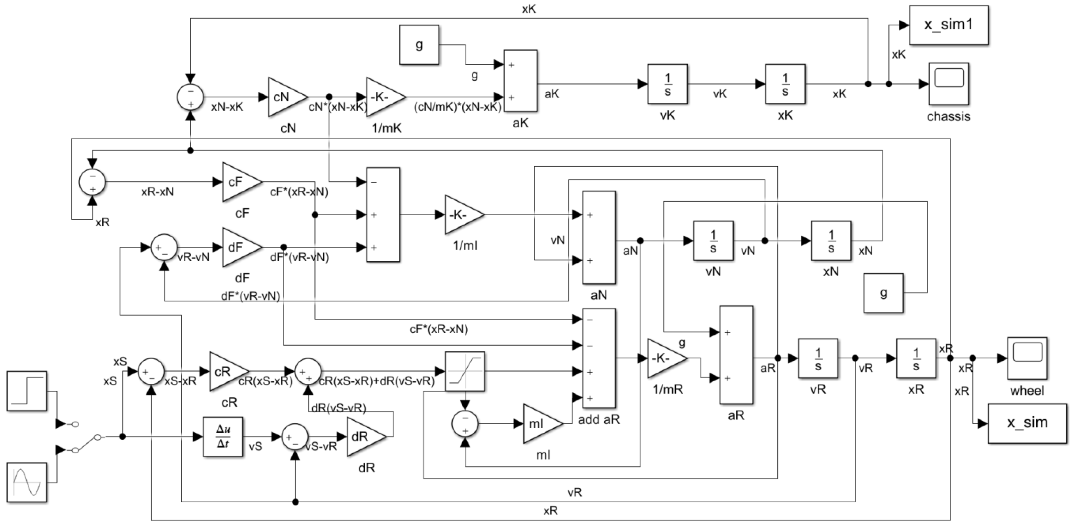
The differential equations were implemented within Simulink as a functional diagram. The resulting functional diagram is shown in Figure 4.
By manipulating a manual switch (on the bottom left side in the diagram), the road input can be switched between step function and sine function. The oscillation of the chassis and the wheel are displayed and evaluated using a graph. The results are stored and compared later in an Excel file, in order to find an optimal setting of the inerter for the different types of vehicles. The Simulink model contains several algebraic loops. This means the solver needs the output signal of a block to calculate its input value at the current time step. Such a kind of signal loop creates a circular dependency and therefore needs an iterative solution procedure in each time-step. For this the in-built MATLAB algebraic-loop solver is used. It is a nonlinear solver, which performs iterations at each time-step to determine the solution to the algebraic constraints [33]. Therefore, simulations containing algebraic loops might run slower compared to models without any circular dependencies. As further simulation settings, the maximum step size and the relative tolerance are set to 10−4. The simulation stop time depends on the kind of road input. For a single-wheel bump, a simulation time of 5 s is enough in most simulations. For the input in shape of a sine function, a simulation time of up to 20 s can be appropriate.
4. Simulation and Sizing Technique of the Inerter for two Different Types of Vehicles
To show the flexibility in the sizing of an inerter design, the simulation is applied to two different types of vehicles. The first vehicle is a 2020 Formula Student race car developed by students of the Ravensburg-Weingarten University (RWU). For this kind of race car, the focus during the design and development phase is on maximizing the mechanical grip to minimize lap time as well as on having a very lightweight design which is easy to integrate in the current vehicle concept. In the second application, the concept of the inerter is integrated into the suspension system of an agricultural tractor. In this design case, the benefit of reducing wheel-load changes is based on the reduction of ground pressure, which improves the soil fertility compared to tractors without such a system. Furthermore, the design of the inerter for this kind of agricultural machine needs to be robust and compact. Both cases will now be described and discussed in detail.
4.1. Formula Student Race Car
The 2020 Formula Student race car of the Formula Student Team Weingarten has a dead weight of about 165 kg. In ready to race condition, the weight is about 240 kg including the driver. The weight distribution of the vehicle is close to 50/50 and the power output is about 66 kW. The influence of the aerodynamics is crucial. The cl*A is about 5.62 m2 at an aerodynamic efficiency of 2.58. Figure 5 contains a CAD (Computer Aided Design) rendering of the 2020 car.
In the next step, the influence of the inerter on the wheel and chassis oscillations will be analyzed. For the simulation hereafter, the vehicle and model data displayed in Table 1 are used. The simulation is carried out here for one wheel only.
The spring (cF) and the damping ratios (dF) are selected to get an eigenfrequency of 4.0 Hz and an attenuation factor of 70%. The influence of cN, which represents the stiffnesses of the chassis and the suspension parts, is not investigated within this simulation. Therefore, cN is to be considered as constant. The optimization cycle works as follows: the effective inerter mass (mI) is stepwise increased, while the oscillation of the wheel and chassis are analyzed and compared. This is done for both types of road input and the step and sine function. The numerical results of the simulation are illustrated for comparison in Figure 6.
In the case of the step function, the amplitude of the chassis oscillation gets reduced with increasing effective inerter mass. The amplitude of the wheel has its minimum at a mI of 4 kg. At higher masses, the amplitude increases again. For the input of a sine function, the results are a little bit different. The minimum of chassis oscillation is at an effective inerter mass of 6 kg. Any deviation from this value only results in slightly higher amplitudes. However, without inerter the displacement reaches its maximum. The amplitude of oscillation at the wheel strongly decreases with increasing effective inerter mass.
Based on the results of the simulation, several conclusions can be drawn. For a single wheel bump, the amplitude of oscillation of the chassis decreases with the increase of the effective inerter mass. Up to a mI of 4 kg, the same applies to the wheel. With a road input in the form of a sine function, the amplitude of the oscillation of the wheel decreases strongly with increasing mI. The higher amount of inertia also reduces the amount of deflection by the chassis. For this reason, when driving straight ahead, a very high effective inerter mass should be favored. However, for a race car there exists several relevant load cases, which partly occur simultaneously. For example, cornering at a very high speed can be seen as a combination of a step and sine function input. On the one hand, the suspension constantly gets a sine input due to the shape of the road surface, and on the other hand, the outer wheels are in bump, while the inner wheels are in rebound, due to the lateral acceleration. Hence, the starting point for testing the inerter on a real car should be a mI of about 5 kg. This is close to the low point of the chassis oscillation at a sine input and to the minimum of the amplitude by the wheel based on a step input. Furthermore, the amplitude of the chassis for a step input is reduced by 3.0%. On top of that, at a mI of 5 kg, the amount of oscillation by the wheel at a sine input is already lowered by about 21%. The final adjustment of the system working together with all secondary stiffness and friction of the suspension needs to be done on a four or seven post rig [34] and on a road trial.
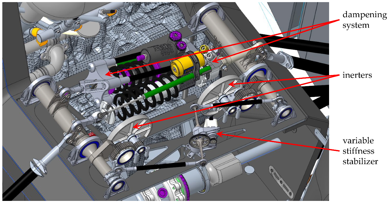
For the design of all modules of the race car, including the frame, suspension and actuators, the team is applying the most advanced state of the art design tools, frameworks and methodologies such as graph-based design languages [35,36], fault-tolerant design [37,38] and design for vibration reduction [39]. The race car suspension system additionally disposes of novel technical systems such as an electrically variable stiffness stabilizer (anti-roll bar) [40] and a dampening system that allows independent adjustment of the roll, heave and pitch dampening [41]. A possible design and installation of the inerters for the 2020 Formula Student car is shown in Figure 7. In this example, the inerter is placed on the rear axle of the car. One inerter is used for each wheel; these inerters are active in roll, heave and pitch movements (compare [41]) of the vehicle.
In Figure 7, the inerter consists of a flywheel made from magnesium and wolfram to achieve a high mass moment of inertia (J = 0.0001 kgm2) at a low weight. The flywheel itself is coupled to the rocker by a gearbox with a transmission of 2.07. The pitch circle radius of the pinion on the shaft of the flywheel is 9 mm. It thus achieves an effective inerter mass of 5 kg per wheel by adding 0.3 kg of extra weight for each inerter unit. The amount of inertia is adjustable by replacing the outer shell of the flywheel, which is made from wolfram. The whole inerter system adds in total about 1.2 kg of extra weight to the race car. According to the team’s lap time simulation, this results in a disadvantage of approximately 0.08 s at a base lap time of 69.79 s. Under the assumption that the inerter system improves the overall mechanical grip by only one percent, the overall lap time improves by 0.35 s to 69.44 s despite the higher car weight. These basic simulations already show the high potential of the system in terms of performance improvement.
4.2. Agricultural Tractor
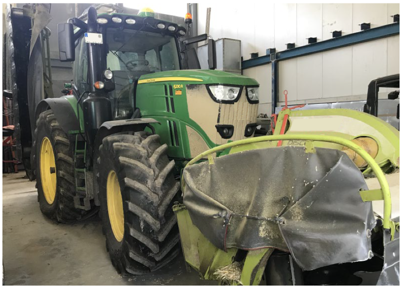
As an example for the flexibility in the usage of the inerter, the application of this system to an agricultural tractor is investigated as well. Therefore, the product data of the tractor in Figure 8 is used. This specific tractor has an overall weight of 13,900 kg and a power output of about 327 kW. The maximum speed is 14 m/s (≈50 km/h). Figure 8 illustrates a concrete example of this kind of agricultural tractor. Any other potentially missing product data which are relevant for the simulation have been estimated based on the intended use.
In the upcoming simulation, the influence of the inerter on wheel and chassis oscillations will be analyzed. For the simulation the vehicle and model data displayed in Table 2 are used. Again, the simulation is done for one wheel only.
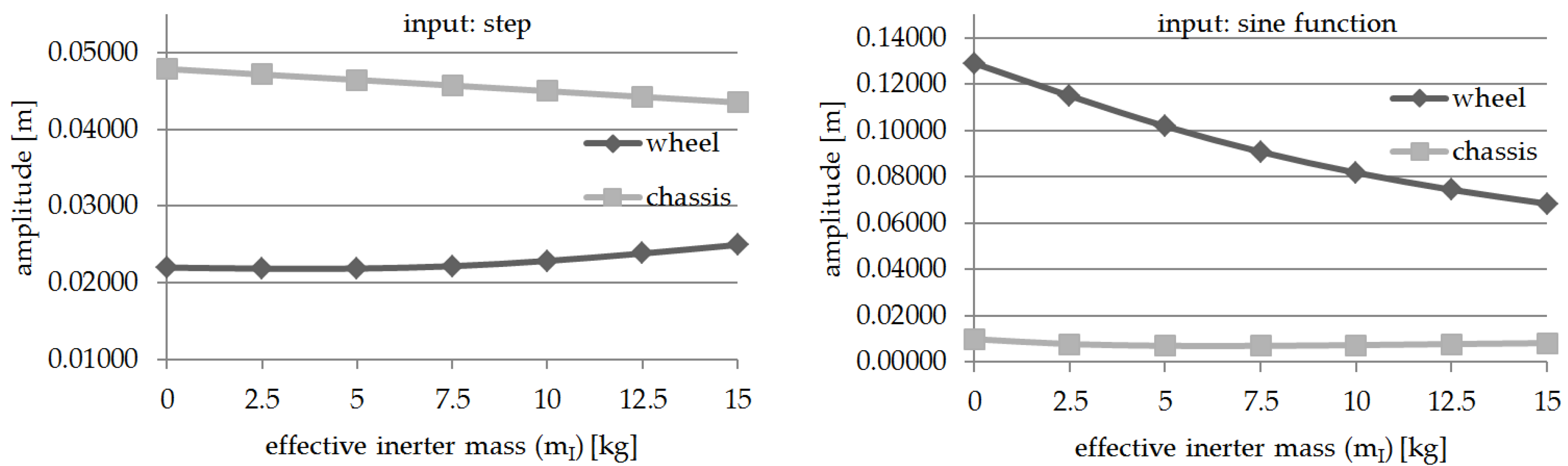
The spring (cF) and the damping ratio (dF) have been selected to get an eigenfrequency of 1.0 Hz and an attenuation factor of 20%. Again, the influence of cN, which represents the stiffnesses of the chassis and the suspension parts, is not investigated within this simulation, and therefore, cN is considered to be constant. The optimization cycle works as follows: the effective inerter mass (mI) is incrementally increased in 50 kg steps, while the oscillation of the wheel and chassis are analyzed and compared. This is done for both types of ground input and the step and sine function. The numerical results of the simulation are illustrated for comparison in Figure 9.
For the step function, the first maximum of the amplitude is investigated. This is for the largest chassis and wheel oscillation without inerter and decreases with an increasing effective inerter mass. The difference is however only very small. Between a mI of 0 kg and 300 kg, the amplitude of the chassis drops by 0.8% and the amplitude of the wheel by 1.3%. However, with the ground input assumed as a sine function, which simulates a constant drive over a field at a speed of 20 km/h, the influence of the inerter on the wheel oscillation is very strong. Therefore, at a mI of 0 kg the amplitude of the wheel is 0.141 m (blue) and drops by 54% to 0.064 m (red) at a mI of 300 kg, which is shown in Figure 10. In both cases, the steady state response to a sine function excitation has been analyzed.
The amplitude of the chassis oscillation remains almost the same. It slightly decreases until an effective inerter mass of 100 kg and then increases again. Thus, for instance, a mI of 0 kg and 270 kg shows the same magnitude of oscillation. The deviation between the maximum and minimum analyzed values is only 0.16 mm.
Based on the analysis performed, the inerter mainly influences the wheel oscillation by a ground input as a sine function. For a tractor, this is the most relevant load case as it simulates the drive over a field at constant speed. As shown in Figure 10, the amplitude of the wheel oscillation is reduced by 54% due to an effective inerter mass of 300 kg. At the same time, the wheel-load oscillations strongly decrease as well, which greatly reduces the ground pressure fluctuations. Thus, peak stresses are attenuated and the load of the tractor is distributed more evenly on the ground. This attenuation helps to preserve the soil structure and thereby maintains the soil fertility.
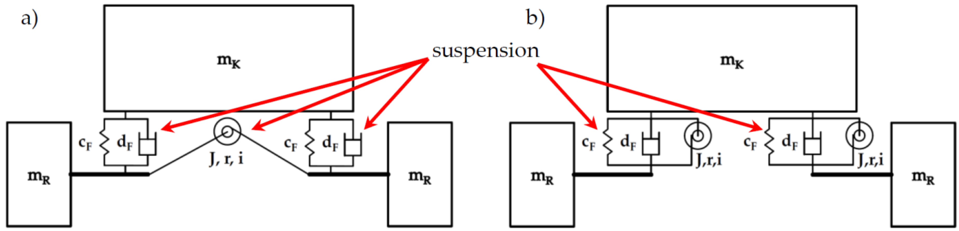
In this application, the inerter is mainly needed in a heave and pitch movement, which offers the opportunity to use only one inerter for each axle of the tractor. This reduces the cost and weight of the overall system, because the inerter is not needed for cornering. The wheels of each axle need to be coupled by the inerter (Figure 11a), which is a comparable installation to a heave or pitch damper of a race car [42]. If this is not possible due to a limited design space, the inerter can be mounted in parallel to the already existing damper of the tractor (Figure 11b).
In both cases, the application of the force at the gearbox of the inerter is done using a spindle, which makes this assembly act against translational accelerations. Due to this design version, the inerter has the same load direction as a common damper [43]. Such an arrangement simplifies the coupling of those two elements. Based on the inerter design used for the Formula Student race car, an effective inerter mass of 300 kg can be achieved due to a transmission of 7.8 in combination with a mass moment of inertia of the flywheel of J = 0.0004 kgm2 and a pitch circle radius of the pinion on the shaft of the flywheel of 9 mm. The estimated weight of the inerter unit is about 0.7 kg due to the bigger flywheel and higher transmission ratio compared to components used in the race car.
5. Conclusions and Recommendations for Further Research
The intention of this paper was to show the potential of using inerters in different kinds of vehicles, which are partly relevant for our daily life but also for specialized applications with different requirements. The presented development is based on theoretical approaches due to simulations and CAD design. Therefore, a Formula Student race car and an agricultural tractor were chosen as lead examples. On the one hand, these are of course two very different kind of vehicles, each with very specialized requirements, but on the other hand, the goal to reduce wheel-load changes remains the same. Since the Formula Student car is solely developed by students of the RWU, the vehicle and the CAD data were available, and therefore, a feasibility study of integrating the inerter into such a kind of vehicle was possible. Furthermore, a first possible design study was undertaken to obtain an estimate of the necessary design space and to determine the extra weight of the system.
The outcome of both analyses are very promising. For the specific tractor the amplitude of wheel oscillation, at a constant drive at 20 km/h over a field, is reduced by about 54% from 0.141 m to 0.064 m. This may be achieved due to an effective inerter mass of 300 kg, which is acting on each wheel. Therefore wheel-load changes strongly decrease, which makes the ground pressure much more constant and preserves the soil structure and thereby helps improve the soil fertility. In the next development steps, this kind of inerter system should be built and tested on a tractor to determine the true improvement of wheel oscillation in an experiment. If these measurements confirm the estimations made in this paper, further development of the inerter should be done in terms of a self-adapting system [44]. Therefore, the flywheel could be coupled to a self-shiftable gearbox, which is dependent on the ground input and changes the transmission and with it the effective inerter mass. This would result in a system which could be advantageously adapted to varying ground surfaces at different vehicle speeds and loading conditions. A possible trade-off could be the robustness and costs of the system.
For the Stinger 20, the current Formula Student race car of the RWU, the expected main benefit consists of a reduction of lap time. A reduction of wheel and chassis oscillation by about 21% improves the contact between the tire and the track surface, which changes the overall grip of the car for the better. Despite the extra weight of the inerter, the lap time is expected to be improved by 0.35 s, according to the results obtained in the lap time simulation. This improvement in terms of lap time seems to be very little at first sight, but in motorsports a few hundreds of a second can make a difference. The further development steps in using inerters in a Formula Student car should therefore focus on weight and design space reduction. Furthermore, the benefit of the inerter must be tested experimentally in the future on a four or seven post rig and on the race track itself.
This paper has given an overview of the idea of how to use inerters in different kinds of vehicles and showed the potential of the application. Furthermore, the design and development process for this kind of system has been illustrated and recommendations for further research have been made.
Author Contributions
Conceptualization, J.B., R.S. and S.R.; methodology, J.B.; design and dimensioning, J.B.; simulation, J.B.; analysis and evaluation, J.B., R.S. and S.R.; writing—original draft preparation, J.B.; writing—review and editing, R.S. and S.R. All authors have read and agreed to the published version of the manuscript.
Funding
This research was partly funded in the scope of the Digital Product Life Cycle (ZaFH) project (information under: https://dip.reutlingen-university.de/), which is supported by a grant from the European Regional Development Fund and the Ministry of Science, Research, and the Arts of Baden-Württemberg, Germany (information under: https://efre-bw.de/).
Acknowledgments
The authors wish to thank the administrative and technical staff of Ravensburg-Weingarten University (RWU), for the continuous support of the formula student team and all involved students for their immense contribution, see https://www.fsteamweingarten.de/. The authors would also like to thank two anonymous reviewers for their constructive comments which helped to clarify several points in the paper.
Conflicts of Interest
The authors declare no conflict of interest.
References
- Smith, M.C. Synthesis of mechanical networks: The inerter. IEEE Trans. Autom. Control 2002, 47, 1648–1662. [Google Scholar] [CrossRef] [Green Version]
- Wang, F.C.; Chen, C.W.; Hong, M.F. Building suspensions with inerters. Proc. Inst. Mech. Eng. Part C J. Mech. Eng. Sci. 2010, 224, 1605–1616. [Google Scholar] [CrossRef]
- De Angelis, M.; Giaralis, A.; Petrini, F.; Pietrosanti, D. Optimal tuning and assessment of inertial dampers with grounded inerter for vibration control of seismically excited base-isolated systems. Eng. Struct. 2019, 196, 109250. [Google Scholar] [CrossRef]
- Radu, A.; Lazar, I.F.; Neil, S.A. Performance-based seismic design of tuned inerter dampers. Struct. Control Health Monit. 2019, 26. [Google Scholar] [CrossRef] [Green Version]
- Marian, L.; Giaralis, A. Optimal design of a novel tuned mass-damper-inerter (TMDI) passive vibration control configuration for stochastically support-excited structural systems. Probabilistic Eng. Mech. 2014, 38, 156–164. [Google Scholar] [CrossRef]
- Sun, L.; Hong, D.; Chen, L. Cables interconnected with tuned inerter damper for vibration mitigation. Eng. Struct. 2017, 151, 57–67. [Google Scholar] [CrossRef]
- Brzeski, P.; Lazarek, M.; Perlikowski, P. Experimental study of the novel tuned mass damper with inerter which enables changes of inertance. J. Sound Vib. 2017, 404, 47–57. [Google Scholar] [CrossRef]
- Chen, M.Z.Q.; Hu, Y.; Huang, L.; Chen, G. Influence of inerter on natural frequencies of vibration systems. J. Sound Vib. 2013, 333, 1874–1887. [Google Scholar] [CrossRef] [Green Version]
- Li, C.; Liang, M.; Wang, Y.; Dong, Y. Vibration suppression using two-terminal flywheel. Part I: Modeling and characterization. J. Vib. Control. 2011, 18, 1096–1105. [Google Scholar] [CrossRef]
- Ge, Z.; Wang, W. Modeling, testing, and characteristic analysis of a planetary flywheel inerter. Shock. Vib. 2018, 2018, 2631539. [Google Scholar] [CrossRef] [Green Version]
- Mahato, A.C.; Ghoshal, S.K.; Samantaray, A.K. Influence of variable inertia flywheel and soft switching on a power hydraulic system. Springer Nat. Appl. Sci. 2019, 1. [Google Scholar] [CrossRef] [Green Version]
- Marian, L.; Giaralis, A. The tuned mass-damper-inerter for harmonic vibrations suppression, attached mass reduction, and energy harvesting. Smart Struct. Syst. 2017, 19, 665–678. [Google Scholar] [CrossRef]
- Petrini, F.; Giaralis, A.; Wang, Z. Optimal tuned mass-damper-inerter (TMDI) design in wind-excited tall buildings for occupants’ comfort serviceability performance and energy harvesting engineering. Structures 2020, 204, 109904. [Google Scholar] [CrossRef]
- Evangelou, S.; Limebeer, D.J.N.; Sharp, R.S.; Smith, M.C. Steering compensation for high-performance motorcycles. In Proceedings of the IEEE Conference on Decision and Control, Nassau, Bahamas, 14–17 December 2004. [Google Scholar] [CrossRef]
- Yang, S. Development of Non-linear Two Terminal Mass Components for Application to Vehicle Suspension Systems. Ph.D. Thesis, University of Ottawa, Ottawa, ON, Canada, 2017. [Google Scholar]
- Wang, F.C.; Yu, C.H.; Chang, M.L.; Hsu, M. The performance improvements of train suspension systems with inerters. In Proceedings of the 45th IEEE Conference on Decision and Control, San Diego, CA, USA, 13–15 December 2006; pp. 1472–1477. [Google Scholar] [CrossRef]
- Soong, M.F.; Ramli, R.; Mahadi, W.N.L.W. Vehicle suspensions with parallel inerter: Effectiveness in improving vibration isolation. J. Vibroeng. 2014, 16, 256–265. [Google Scholar]
- Shi, X.; Zhu, S. A comparative study of vibration isolation performance using negative stiffness and inerter dampers. J. Frankl. Inst. 2019, 356, 7922–7946. [Google Scholar] [CrossRef]
- Li, C.; Liang, M.; Wang, Y.; Dong, Y. Vibration suppression using two-terminal flywheel. Part II: Application to vehicle passive suspension. J. Vib. Control 2011, 18, 1353–1365. [Google Scholar] [CrossRef]
- Formula 1 Dictionary. Available online: http://www.formula1-dictionary.net/j-damper.html (accessed on 6 April 2020).
- Von Wysocki, T.; Chakar, J.; Gauterin, F. Small changes in vehicle suspension layouts could reduce interior road noise. Vehicles 2020, 2, 2. [Google Scholar] [CrossRef] [Green Version]
- Pischinger, S.; Seiffert, U. Vieweg Handbuch Kraftfahrzeugtechnik, Systeme; Springer: Wiesbaden, Germany, 2016; Volume 8, pp. 743–744. [Google Scholar] [CrossRef]
- Wittel, H.; Jannasch, D.; Voßiek, J.; Spura, C. Roloff/Matek Maschinenelemente—Normung, Berechnung, Gestaltung; Springer: Berlin/Heidelberg, Germany, 2019; Volume 24, pp. 338–340. [Google Scholar] [CrossRef]
- Dixon, J.C. The Shock Absorber Handbook; Wiley-Professional Engineering Publishing Series; John Wiley & Sons, Ltd.: West Sussex, England, 2007; Volume 2, pp. 259–263. [Google Scholar]
- Heißing, B.; Ersoy, M.; Gies, S. Fahrwerkhandbuch—Grundlagen, Fahrdynamik, Komponenten, Systeme, Mechatronik, Perspektiven; Springer: Wiesbaden, Germany, 2013; Volume 4, p. 252. [Google Scholar] [CrossRef]
- OptimumG. Available online: https://optimumg.com/spring-dampers-part-four/ (accessed on 11 May 2020).
- Trzesniowski, M. Rennwagentechnik—Grundlagen, Konstruktion, Komponenten, Systeme; Springer: Wiesbaden, Germany, 2014; Volume 4. [Google Scholar] [CrossRef]
- Société de Technologie Michelin. The Tyre—Grip; Société de Technologie Michelin: Clermont-Ferrand, France, 2001. [Google Scholar]
- Jäger, H.; Mastel, R.; Knaebel, M. Technische Schwingungslehre—Grundlagen, Modellbildung, Anwendungen; Springer Vieweg: Wiesbaden, Germany, 2016; Volume 9. [Google Scholar] [CrossRef]
- Schramm, D.; Hiller, M.; Bardini, R. Modellbildung und Simulation der Dynamik von Kraftfahrzeugen; Springer: Berlin/Heidelberg, Germany, 2013; Volume 2, pp. 307–339. [Google Scholar] [CrossRef]
- Dresig, H.; Holzweißig, F. Maschinendynamik; Springer Vieweg: Berlin/Heidelberg, Germany, 2012; Volume 11, pp. 45–48. [Google Scholar] [CrossRef]
- Mukherjee, A.; Majhi, S. Characterisation of road bumps using smartphones. Eur. Transp. Res. Rev. 2016. [Google Scholar] [CrossRef] [Green Version]
- MathWorks. Available online: https://de.mathworks.com/help/simulink/ug/algebraic-loops.html (accessed on 6 May 2020).
- Trzesniowski, M.; Eder, P. Handbuch Rennwagentechnik—Datenanalyse, Abstimmung und Entwicklung; Springer: Wiesbaden, Germany, 2017; Volume 3, pp. 326–330. [Google Scholar] [CrossRef]
- Ramsaier, M.; Stetter, R.; Till, M.; Rudolph, S. Modelling and simulation of a race-car frame using graph-based design languages. In EngOpt 2018 Proceedings of the 6th International Conference on Engineering Optimization; Rodrigues, H.C., Herskovits, J., Mota Soares, C.M., Araújo, A.L., Guedes, J.M., Folgado, J.O., Moleiro, F., Madeira, J.F.A., Eds.; Springer: Cham, Switzerland, 2018; pp. 789–800. [Google Scholar]
- Gross, J.; Rudolph, S. Modeling graph-based satellite design languages. Aerosp. Sci. Technol. 2016, 49, 63–71. [Google Scholar] [CrossRef]
- Stetter, R. Fault-Tolerant Design and Control of Automated Vehicles and Processes; Insights for the Synthesis of Intelligent Systems; Springer: Berlin/Heidelberg, Germany, 2020. [Google Scholar] [CrossRef]
- Stetter, R.; Göser, R.; Gresser, S.; Till, M.; Witczak, M. Fault-tolerant design for increasing the reliability of an autonomous driving gear shifting system. Eksploat. Niezawodn. Maint. Reliab. 2020, 22, 482–492. [Google Scholar] [CrossRef]
- Sturm, C.; Bremer, F.; Matthiesen, S. Design for vibration reduction—An overview of models for product development with focus on excitation and transmission of vibrations of technical systems. Procedia CIRP 2019, 84, 662–666. [Google Scholar] [CrossRef]
- Borowski, J. Entwicklung, Konstruktion und Abstimmung eines aktiven Stabilisators für ein Formula Student Fahrzeug. Bachelor′s Thesis, Ravensburg-Weingarten University (RWU), Weingarten, Germany, 2016. [Google Scholar]
- Borowski, J. Entwicklung und Konstruktion eines Roll-, Hub- und Nickfahrwerks für ein Formula Student Fahrzeug. Master′s Thesis, Ravensburg-Weingarten University (RWU), Weingarten, Germany, 2019. [Google Scholar]
- OptimumG. Available online: https://optimumg.com/spring-dampers-part-six/ (accessed on 15 May 2020).
- Milliken, W.F.; Milliken, D.L. Race Car Vehicle Dynamics; Society of Automotive Engineers, Inc.: Warendale, PA, USA, 1995; ISBN 1-56091-526-9. [Google Scholar]
- Jackson, R.L. Self adapting mechanical step bearings for variations in load. Tribol. Lett. 2005, 20. [Google Scholar] [CrossRef]
Figure 1.
Flywheel and gearbox.

Figure 2.
Physical model.

Figure 3.
Example of different stiffnesses of cN.

Figure 4.
Functional diagram in MATLAB/Simulink.

Figure 5.
2020 race car of the Formula Student Team Weingarten.

Figure 6.
Results of the simulation for the Formula Student car.

Figure 7.
Inerter placed in the ‘Stinger 20’ of the Formula Student Team Weingarten.

Figure 8.
Agricultural tractor.

Figure 9.
Results of the simulation for the specific tractor.

Figure 10.
Wheel oscillation of the specific tractor at a constant drive over a field.

Figure 11.
Principal design structure with one inerter (a) and two inerters (b) per axle.


Table 1.
Simulation parameters of the Formula Student car.
| Parameter | Value |
|---|---|
| mK | 60 kg |
| mR | 8 kg |
| cF | 35,000 N/m |
| cR | 100,000 N/m |
| dF | 2000 Ns/m |
| dR | 10 Ns/m |
| step | 0.05 m |
| speed | 16.67 m/s (=60 km/h) |
Table 2.
Simulation parameters of the specific tractor.
| Parameters | Value |
|---|---|
| mK | 4000 kg |
| mR | 200 kg |
| cF | 158,000 N/m |
| cR | 200,000 N/m |
| dF | 10,050 Ns/m |
| dR | 5 Ns/m |
| step | 0.20 m |
| speed | 5.56 m/s (=20 km/h) |
© 2020 by the authors. Licensee MDPI, Basel, Switzerland. This article is an open access article distributed under the terms and conditions of the Creative Commons Attribution (CC BY) license (http://creativecommons.org/licenses/by/4.0/).
Share and Cite
MDPI and ACS Style
Borowski, J.; Stetter, R.; Rudolph, S. Design, Dimensioning and Simulation of Inerters for the Reduction of Vehicle Wheel Vibrations—Case Studies. Vehicles 2020, 2, 424-437. https://0-doi-org.brum.beds.ac.uk/10.3390/vehicles2030023
AMA Style
Borowski J, Stetter R, Rudolph S. Design, Dimensioning and Simulation of Inerters for the Reduction of Vehicle Wheel Vibrations—Case Studies. Vehicles. 2020; 2(3):424-437. https://0-doi-org.brum.beds.ac.uk/10.3390/vehicles2030023
Chicago/Turabian StyleBorowski, Julian, Ralf Stetter, and Stephan Rudolph. 2020. "Design, Dimensioning and Simulation of Inerters for the Reduction of Vehicle Wheel Vibrations—Case Studies" Vehicles 2, no. 3: 424-437. https://0-doi-org.brum.beds.ac.uk/10.3390/vehicles2030023