Article

Fluid-Structure Interaction Analysis of Subject-Specific Mitral Valve Regurgitation Treatment with an Intra-Valvular Spacer

by
Milan Toma
1,2,*,
Daniel R. Einstein
3,
Charles H. Bloodworth IV
2,
Keshav Kohli
2,
Richard P. Cochran
4,
Karyn S. Kunzelman
4 and
Ajit P. Yoganathan
2
1
Department of Osteopathic Manipulative Medicine, College of Osteopathic Medicine, New York Institute of Technology, Old Westbury Campus, Northern Boulevard, Old Westbury, NY 11568-8000, USA
2
Wallace H. Coulter Department of Biomedical Engineering, Georgia Institute of Technology and Emory University, Technology Enterprise Park, Suite 200, 387 Technology Circle, Atlanta, GA 30313-2412, USA
3
Department of Mechanical Engineering, St. Martin’s University, 5000 Abbey Way SE, Lacey, WA 98503, USA
4
Department of Mechanical Engineering, University of Maine, 219 Boardman Hall, Orono, ME 04469-5711, USA
*
Author to whom correspondence should be addressed.
Submission received: 1 May 2020 / Revised: 19 May 2020 / Accepted: 20 May 2020 / Published: 23 May 2020

Abstract

:
Mitral regurgitation imposes a significant symptomatic burden on patients who are not candidates for conventional surgery. For these patients, transcatheter repair and replacement devices are emerging as alternative options. One such device is an intravalvular balloon or spacer that is inserted between the mitral valve leaflets to fill the gap that gives rise to mitral regurgitation. In this study, we apply a large-deformation fluid-structure interaction analysis to a fully 3D subject-specific mitral valve model to assess the efficacy of the intra-valvular spacer for reducing mitral regurgitation severity. The model includes a topologically 3D subvalvular apparatus with unprecedented detail. Results show that device fixation and anchoring at the location of the subject’s regurgitant orifice is imperative for optimal reduction of mitral regurgitation.

1. Introduction

Mitral valve regurgitation (MR) is the most prevalent form of valvular heart disease, affecting more than 4 million people in the United States [1]. The gold standard therapy for MR correction is surgical repair or replacement. However, 49% of patients are denied surgical options due to high surgical risk [2]. Minimally invasive mitral repair and replacement devices are therefore emerging as alternative options to treat patients who are considered non-surgical candidates. Currently, only the MitraClip device has been approved by the FDA for the percutaneous treatment of degenerative MR (DMR). However, there are no currently approved devices for the percutaneous treatment of functional MR (FMR).
The Mitra-Spacer (Cardiosolutions, Brigewater, MA, USA) is a novel transcatheter device under development and early clinical evaluation for the treatment of FMR in patients at high risk for surgery. The device consists of a fluid-filled balloon designed to occupy the regurgitant orifice of the mitral valve (MV), with intra-valvular fixation established by an apical anchor. When positioned in the MV regurgitant orifice, the Mitra-Spacer blocks regurgitant flow and improves MV leaflet coaptation, therefore reducing FMR severity [3]. This study aims to evaluate the efficacy of an intra-valvular spacer in silico for the treatment of FMR in a subject-specific computational model.
Decades ago, finite element analysis was introduced to investigate the mechanics governing normal [4], diseased [5,6,7] and surgically repaired [8,9,10,11] MV functions. More recently, fluid-structure interaction (FSI) analysis was introduced to understand the complex dynamics of mitral valvular function [12,13,14,15,16,17]. The MV geometries utilized by these studies were obtained either by parametric modeling of excised specimens or by image reconstruction derived from a discrete set of markers placed on the valvular apparatus, both of which resulted in topologically two-dimensional leaflets and topologically one-dimensional chordae [15,18,19,20,21,22,23,24]. This inability to realistically represent the complex chordal structure and its transition to the leaflets has been one of the obstacles to predictive fluid-structure interaction models of the native mitral valve. These prior simplifications of the MV geometry were motivated principally by two factors. First, past computational resources mandated computational efficiency. Secondly, past imaging modalities were not of sufficient resolution and past image-processing techniques were not sufficiently evolved.
These simplifications of valvular geometry enabled interesting studies that have increased our understanding of valvular dynamics. However, they are not anatomically nor mechanically correct. Indeed, the chordae are not mechanically discrete but rather are a detailed 3-D branching structure that transitions continuously and gradually into the anterior and posterior leaflets with a unified collagen fiber architecture. Moreover, the chordae act as secondary orifices for blood flow, creating a dynamic interface between blood and tissue that is geometrically complex. Omission of the fluid-structure interaction between the blood and the 3D structure of the chordae has therefore been a major limitation and has been an obstacle to truly patient-specific modeling.
Recently, we developed and validated an ex-vivo MV imaging methodology used for computer simulations with fully three-dimensional patient-specific MV geometries, affording an unprecedented level of leaflet and chordal detail [25] (Figure 1). In a number of recent studies, we developed and validated FSI models and methods based on these valve-specific geometries to simulate MV closure [25,26,27]. In this study, we apply this new simulation capability to an explanted ovine MV to assess the efficacy of a intra-valvular spacer for the treatment of functional MV regurgitation.

2. Materials and Methods

Below we briefly summarize our approach to developing valve-specific geometries from micro-computed tomography ( μ CT) data; how we develop the valve-specific 3D fiber-orientation architectures for those geometries; and lastly how we develop these data into numerical models for examining the structural and fluid mechanics of the mitral valve. These methods have been extensively described elsewhere [25,26,27]. In the last subsection, we describe how we applied these methods to examine the affect of spring stiffness on the position of the spacer at systole, when the valve leaflets close, and consequently the affect of spring stiffness on reduction of regurgitant orifice area.

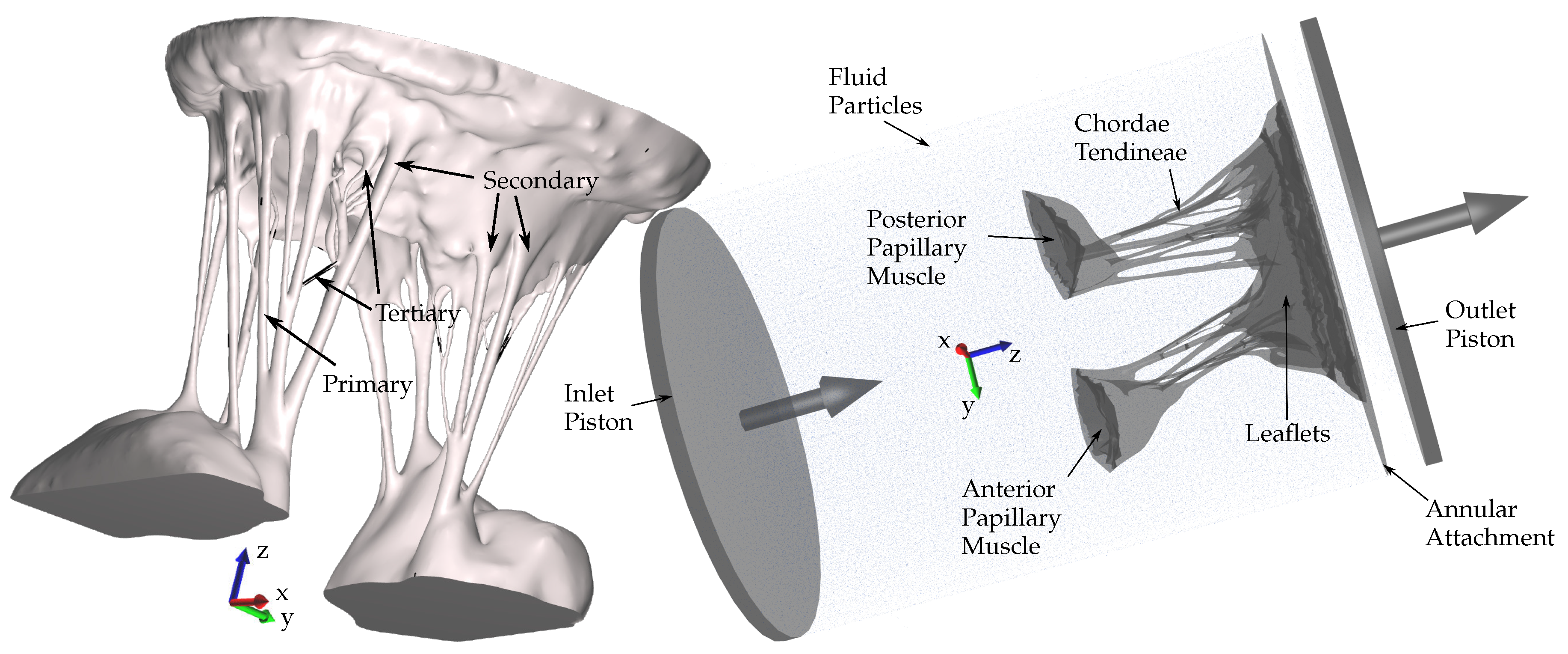
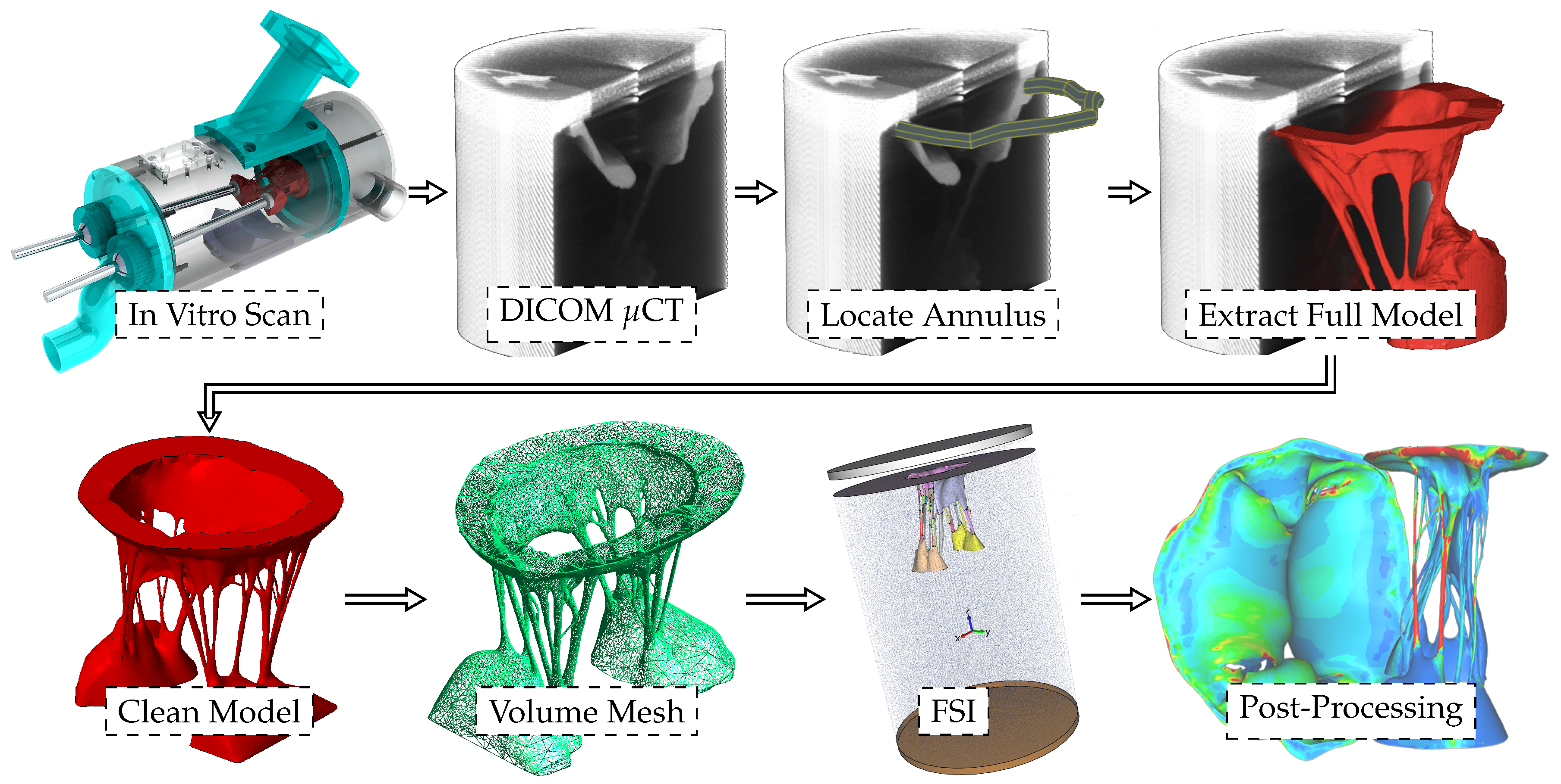
2.1. Model Development

To date, no clinical imaging modality is capable of visualizing the complete mitral valvular and sub-valvular anatomy with adequate spatial or temporal resolution for accurate computational modeling. Thus, the model geometry for this study was developed from μ CT data of an intact, explanted ovine MV, within a water-filled chamber that was specifically designed to be a removable component of our extensively validated Georgia Tech Left Heart Simulator [26,28]. Following imaging, μ CT data were registered to measurement data from the left heart simulator and then segmented. The resulting surface was then cleaned to remove degenerate triangles and a scale-invariant volume mesh was generated as described in [29]. Figure 2 provides an overview of the model development. Importantly, registration of the μ CT data to measurement data from the left heart simulator enables direct comparisons between model predictions and in-vitro measurements, providing data in the form of chordal force and direction, fluid flow and high-speed camera images for model validation.
In our previous studies we have examined both normal, “healthy” mitral valves [26] (Figure 3a), and regurgitant valves [30]. In these studies, we have shown that the predicted geometric configuration and coaptation line shows strong agreement to μ CT data of the same closed valve. Further validation took the form of close agreement between the predicted dynamic forces on the chordae tendineae throughout the cardiac cycle with experimentally measured data of the same valve [16]. In one such study, we simulated chordal rupture [30] and concomitant mitral regurgitation. In the current study, focused on assessing the efficacy of an intra-valvular spacer, we adopted the model geometry and parameters from the chordal rupture study that resulted in the greatest regurgitant orifice area (Figure 3b).

2.2. Fiber Orientation

The mitral valve is a complex structure of articulated collagen arranged in a network that determines the valve’s mechanical behaviour. That behavior is both anisotropic and highly nonlinear. Thus, determining the local fiber orientation in valve leaflets and chordae is critical to accurate predictions of MV fluid-structure interaction. It is also challenging. A thorough review is provided in [26].
Our approach is a geometric technique that is subject to experimentally determined boundary conditions. The approach, while not perfect, is fast, fundamentally three-dimensional, requires no invasive experimental techniques, and accommodates a realistic transition between chordae and leaflets that is critical to accurate fluid-structure interaction studies.
Specifically, let Ω be the volume over which fiber orientations need be determined, and S be the set of seed points where the fiber directions d ^ are known. In other words, d ^ are the experimentally determined boundary conditions. To evolve a 3D vector field over Ω from these measured boundary values, we solve Laplace’s equation for the 3 × 3 matrix M over Ω with Dirichlet boundary data constructed from d ^ :
2 M ( x ) = 0 , x Ω \ S M ( x ) = d ^ d ^ T , x S .
The solution M ( x ) over Ω \ S is then decomposed into an eigenvalue decomposition:
M = E λ 1 0 0 0 λ 2 0 0 0 λ 3 E T ,
with λ 1 λ 2 λ 3 0 . The first (orthonormal) column vector e 1 in E is taken to be the fiber direction at each point x in Ω \ S , where the eigenvalue solution simply unpacks the square matrix M .

2.3. Constitutive Model

With fiber direction determined for papillary muscle, chordae and leaflets, we adopted an unified constitutive model based on an approximation of a three-dimensional Gaussian distribution of fibers [31]. The model is defined in terms of a strain energy function given in [31]. In terms of the 2nd Piola-Kirchhoff stress, S :
S = κ J ( J 1 ) C 1 + μ J 2 / 3 Dev [ ( I C ¯ 2 ) / 4 ] + + σ ( λ ) J 2 / 3 Dev [ K ] + ϵ ( λ ) J 2 / 3 Dev [ K ] ,
where J is Jacobian, κ is bulk modulus, σ is passive fiber stress-strain rule for the fiber population, ϵ is active fiber stress-strain rule, Dev is deviatoric projection operator, and C is right-Cauchy deformation, and λ is dispersed fourth invariant defined as
λ 2 = tr ( K C ¯ ) ,
where C ¯ is the isochoric part of the right-Cauchy deformation, K is called the dispersion tensor or anisotropy tensor and is given in global coordinates. The specific fiber stress-strain rule σ we adopted was the a micro-structural model presented in [31] based on the physiology of crimped collagen fibers.

2.4. Numerical Methods

FSI was modeled by simultaneously solving smoothed particle hydrodynamics (SPH) equations for the fluid and the large deformation solid mechanics equations for the MV. The SPH equations are described in more detail elsewhere [27]. Using SPH as opposed to more traditional computational methods is preferred due to their limitations demonstrated in [32]. The methods used in this study have been implemented in other biomedical applications with complex geometries as well [33]. The IMPETUS Afea SPH Solver® (IMPETUS Afea AS, Norway), and IMPETUS Afea Solver® were used for all simulations. Both fluid and solid domains, and their interaction, were solved with an explicit time-integration scheme. All simulations were solved on a standard workstation. Parallel acceleration was achieved with a Tesla K40 GPU with 12 GB of Graphic DDR memory and 2880 CUDA Cores.
To confirm that convergence was reached, refinement and coarsening of the finite element mesh (h-refinement) was performed. After testing meshes of three different resolutions (92,640 elements, ±20%), all solutions were found to converge to within 5% of each other. The final model consisted of 92,640 fully-integrated, quadratic tetrahedral elements and 476,199 fluid particles. Fluid particles were confined to a rigid structure that replicated the geometry of the experimental chamber (Figure 2). To impose prescribed velocity boundary conditions in accordance with measured flows, the ends of the chamber were moved at the known prescribed velocity, resulting in piston-like displacement of the fluid particles (Figure 1). Nodes at the bottom of the papillary muscles and around the annular attachment were fixed in all three directions.

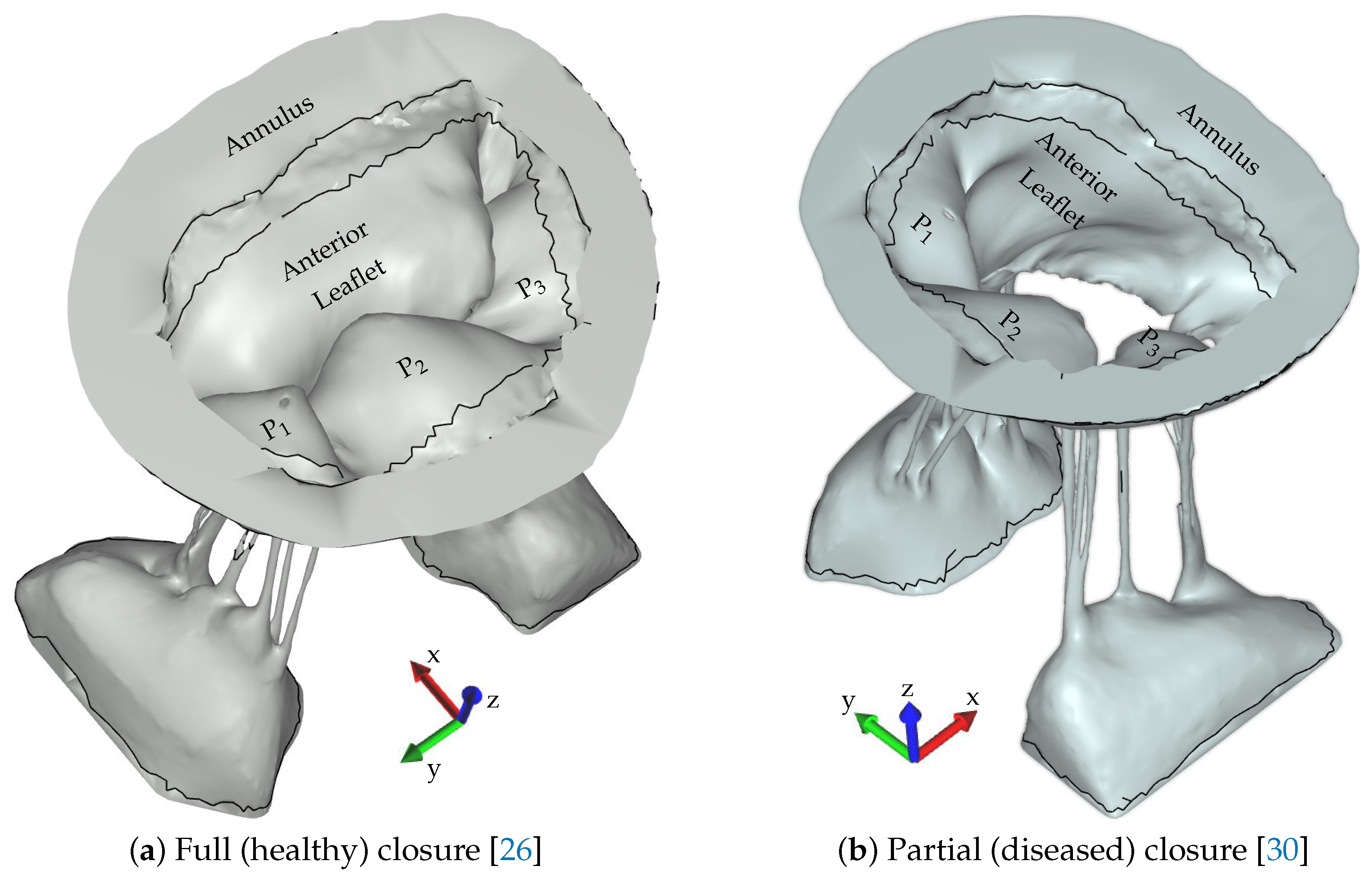
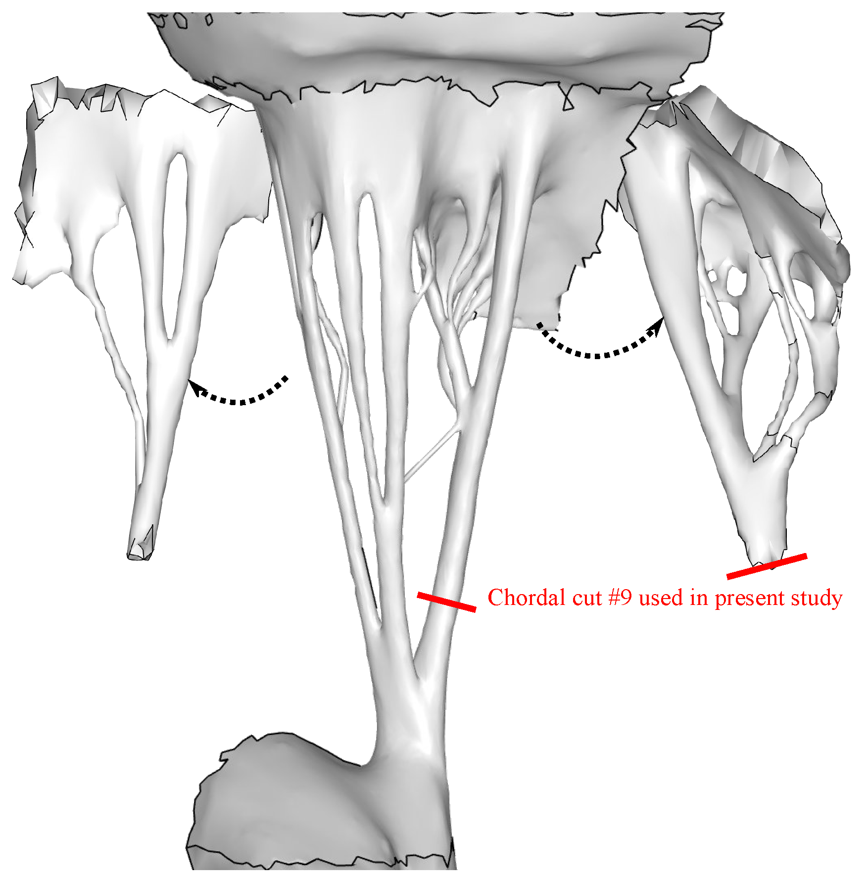
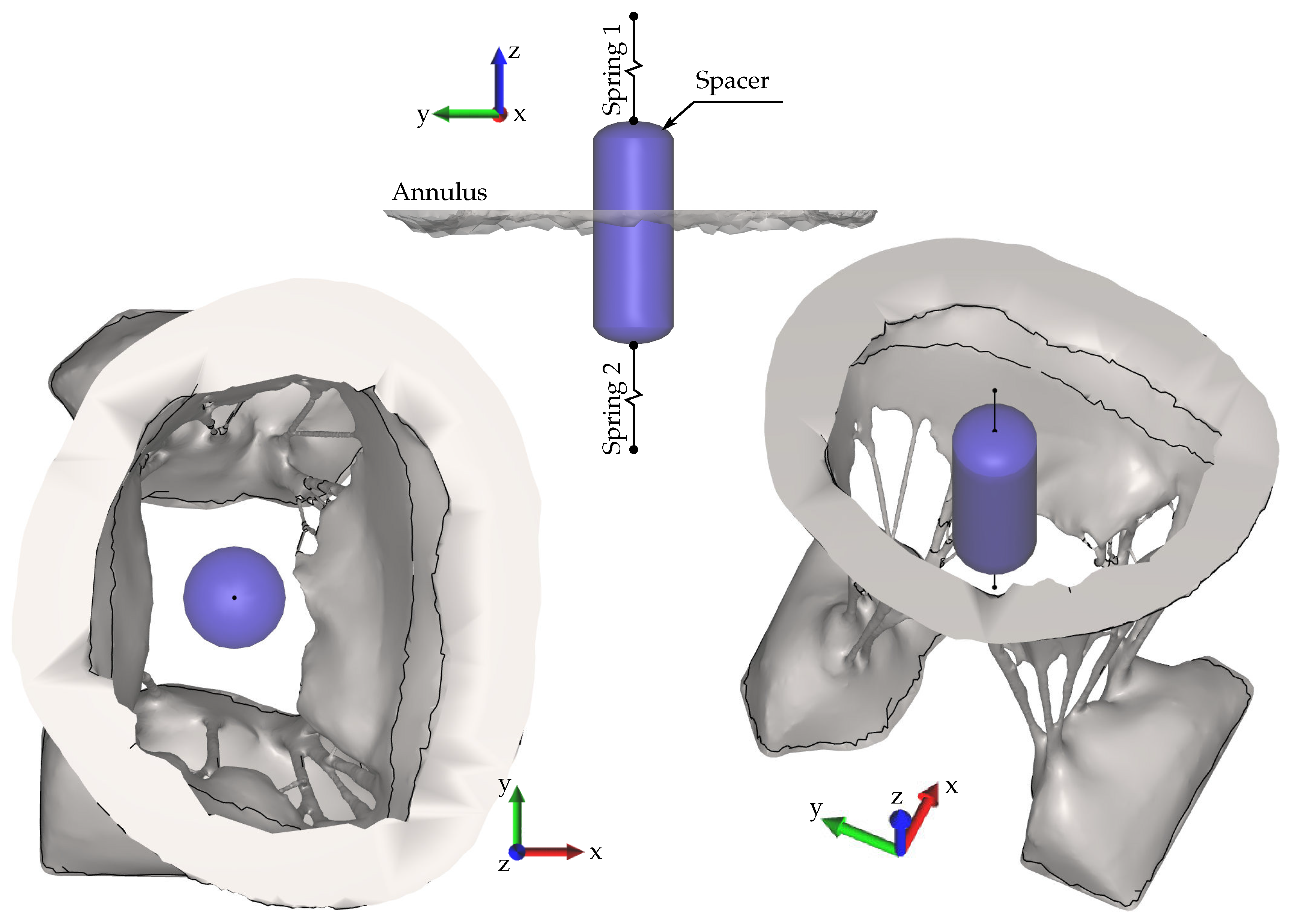
2.5. Application to Assessment of Spacer Efficacy
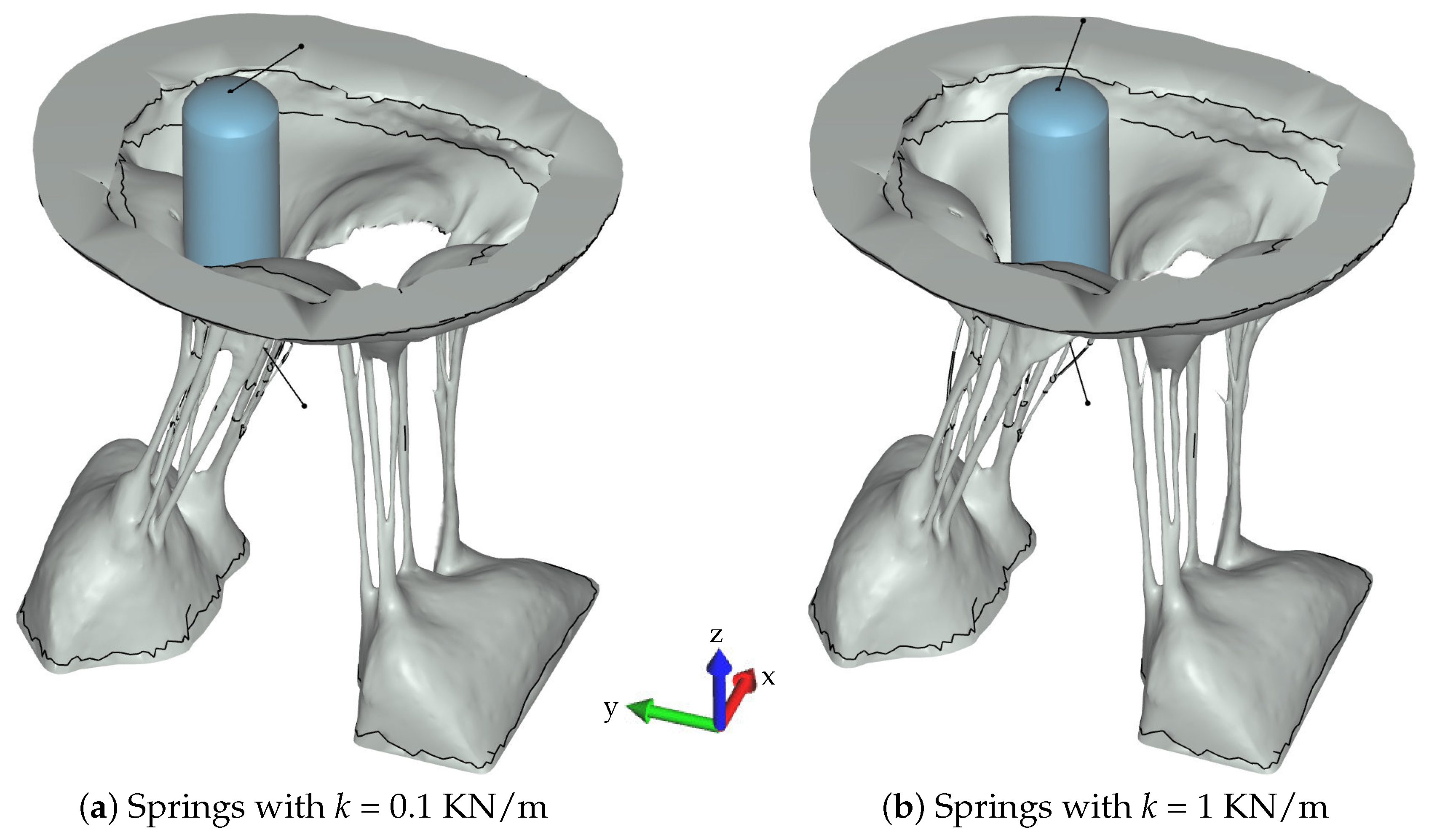
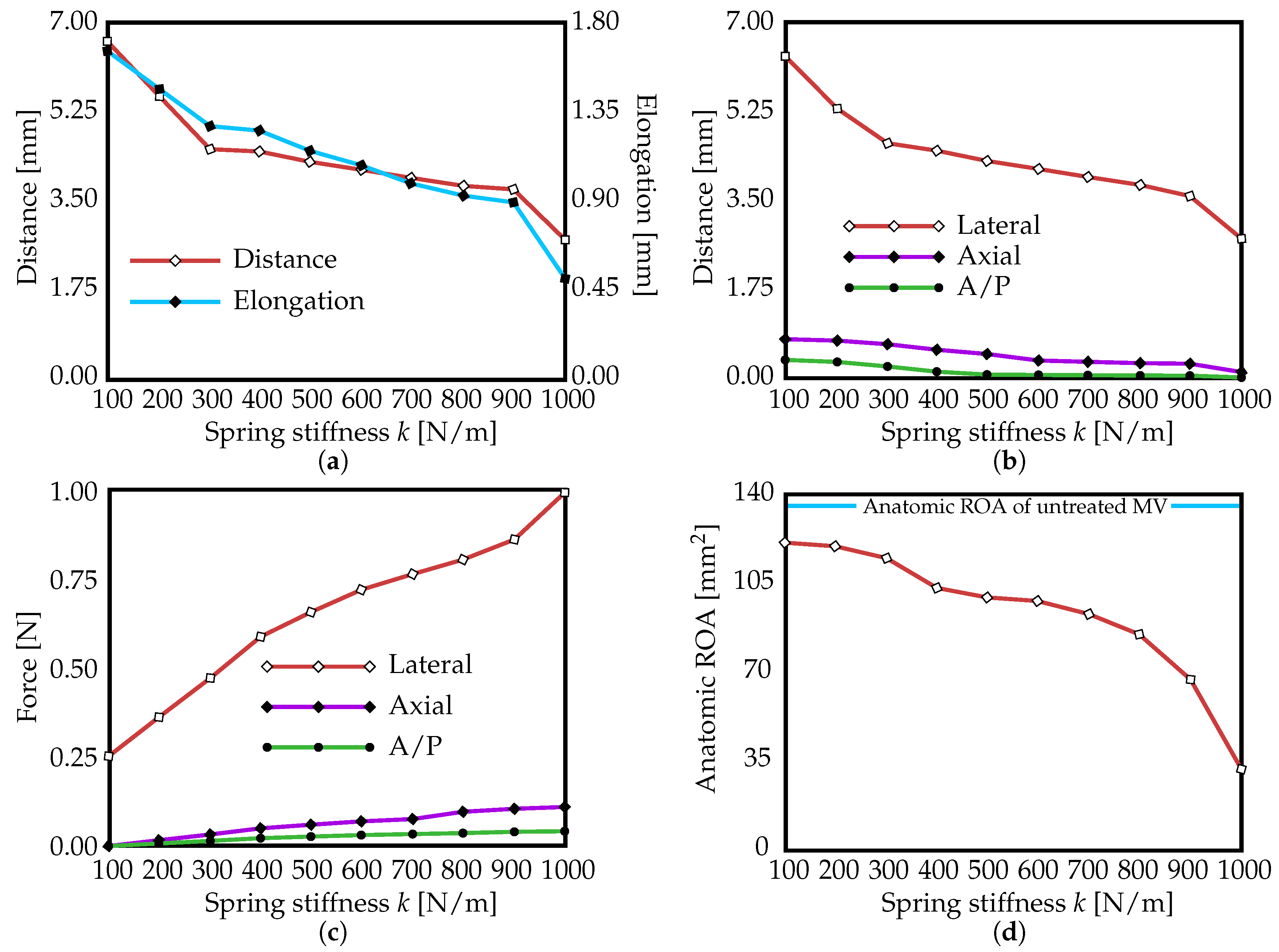
In a recent study, we investigated the sensitivity of mitral prolapse and regurgitation to 51 possible chordae tendineae rupture points based on clinical reports [34,35,36,37,38]. To simulate rupture, we removed elements from our validated model such that—one at a time—each rupture point was detached. We then observed the resultant regurgitant orifice area (ROA) and the change in strain in the subvalvular apparatus. In this study, we adopted the geometry corresponding to rupture point # 9 (Figure 4) from that study because it led to the greatest amount of ROA (also shown in Figure 3). Specifically, the baseline ROA for the adopted geometry was 134 mm 2 .
Measurements of the spacer (Figure 5) were obtained from a prototype provided by Cardiosolutions, Brigewater, MA, USA. Its size, shape and location relative to the MV geometry is shown in Figure 5. In its clinical application, the spacer is held in place using two springs of equal length and stiffness. This deployment was replicated in the computational model. The spacer was modeled as rigid balloon with the same density as the fluid; the springs were modeled with spring elements of varying stiffness k = 0.1–1.0 KN/m, a mass of m = 0.01 kg, and a fraction of critical damping (defining the damping force versus elongation rate) of ξ = 0.1. The free ends of the springs were fixed in all three directions. Thus, the spacer was free to move in three dimensions subject the dynamic pressure forces of the transvalvular flow and to the tethering of the springs.
The regurgitant orifice area (ROA) was assessed as follows. First, the nodes enclosing the coaptation line at full closure were identified in the “healthy”, control case. The area, of the polygon in the space formed by the nodes of the coaptation line with coordinates vectors x , y and z was calculated using a function from a library geom3D called polygonArea3d [39]. Due to modeling imperfections the control ROA had a small non-zero value, of 2.13 mm2, which was subtracted from the predictions of ROA in this study [30]. Subsequently, the same nodes were used to compute the enclosed area in the FSI results of the spacer simulations, minus the corresponding cross-sectional area of the spacer.

3. Results

Figure 6 shows the resulting closures and locations of the spacer for two cases in which the stiffness, k, of the springs were 0.1 and 1 KN/m, respectively (the two extremes of spring stiffness investigated in this study). As can be noted, for lower stiffness values (Figure 6a), the spacer is displaced by the regurgitant jet. Results for all values of k are presented in Figure 7. Displacement of the spacer from its original position at time T = 0 s to its position at the time of MV closure, at time T = T s y s , is shown in Figure 7a. On the same graph, spring elongation is shown on the secondary y-axis. As expected, they follow the same pattern. However, it is notable that neither displacement (distance) nor spring elongation are linear functions of spring stiffness. This is due to the fact that the integration of momentum imparted from the fluid to the spacer in part determines the spacer’s position, and that the resultant force is a function of the position of the spacer in the flow.
When the distance is decomposed to lateral (y-axis), axial (z-axis) and A/P (x-axis) directions (Figure 7b), it can be seen that displacement is predominately lateral. In other words, the spacer encounters less resistance from the valve along the free edge from commisure to commisure. This accords with expectations but the magnitude of difference in the three directions is notable. Similarly, the components of force (lateral (y-axis), axial (z-axis) and A/P (x-axis)) with respect to spring stiffness are shown in Figure 7c. Greater lateral force corresponds to greater lateral displacement. Again both lateral force and lateral displacement are non-linear due to the influence of the regurgitant flow.
Finally, Figure 7d shows the anatomic ROA as a function of spring stiffness. The anatomic ROA of the untreated MV (Figure 6b) is also indicated on the graph as a blue line for reference. As the spring stiffness is increased from 0.1 to 1 KN/m, the ROA decreases from about 122 mm 2 to about 30 mm 2 , a reduction factor of about 4.0. Recall that the baseline ROA was 134 mm 2 with no spacer and the control ROA for the “healthy” geometry was 2.13 mm 2 .

4. Discussion

At systolic closing, the position and the concomitant efficacy of the spacer to treat functional mitral regurgitation is a function of the interaction of the spacer with the valvular structure and with the field of dynamic pressures acting at the interface of the spacer and the fluid. Determining the optimum placement of the spacer and the optimum spring stiffness is therefore critical to the clinical success of this treatment for non-surgical candidates. While it is true that the spacer decreases the ROA even at low values of stiffness, it must be remembered that the presence of the spacer imposes a penalty on transvalvular flow during diastole in the sense that the spacer itself is a resistance to flow. Thus, all things being equal, the spacer extracts a metabolic cost. This energy cost is not captured in our simulation. Nevertheless, the case that optimization is necessary and warranted is clear. In this study, we examined the influence of spring stiffness on spacer efficacy for a given spacer size.
Results showed that when the anatomic ROA occurred in the P2/P3 region of the MV, the closing leaflets and the fluid jet pushed the spacer against the opposing P1 leaflet. Hence, if the spacer is allowed to freely move in a crosswise direction under the influence of fluid momentum, it does not improve (decrease) the anatomic ROA (Figure 6). Similarly, in Figure 7d, it can be observed that this treatment has very little effect on the resulting anatomic ROA values if the anchoring springs have insufficient stiffness. Only when the spacer starts affecting the P2/P3 region, i.e., where the highest ROA occurs in the untreated model, is the spacer seen to be effective. Proper anchoring is therefore essential and spring force of at least 1 N is required to maintain the centered position of the spacer (Figure 7c). However, different cases of FMR are apt to lead to different valvular distortions and thus different patterns of fluid motion. With the technology in place, we can begin to address these different cases in a subject-specific manner.

5. Limitations and Future Work

In this study we considered a single case of regurgitation resulting from the rupture of a single chord. The mitral valve is a very heterogeneous structure and it would likely be important to assess the functionality of the spacer in other cases of regurgitation. Furthermore, a one-size-fits-all approach to spacers may not be the best approach. With our model it would be possible to investigate the effects of spacer size and shape on ROA as well as diastolic pressure drop. Such investigations are left to future work.

6. Conclusions

MR imposes a significant symptomatic burden on patients who are denied conventional surgery. The Mitra-Spacer is a novel trans-catheter intra-valvular spacer device currently under early clinical evaluation which may offer high surgical risk patients an alternative option for MR correction. The present study aimed to assess the efficacy of the intra-valvular spacer for reducing MR severity using a novel subject-specific in-silico model. Simulation results show that device fixation and anchoring at the location of the subject’s regurgitant orifice is imperative for optimal reduction of MR. Thus, accurate understanding of patient anatomy and MV function will be important for optimizing procedures with the Mitra-Spacer system. Since blood flow influences valvular mechanics and timing, as well as the position of the intra-valvular spacer during systolic closing, the use of FSI is essential.

Author Contributions

Conceptualization, M.T., C.H.B.IV, D.R.E., R.P.C., K.S.K. and A.P.Y.; methodology, M.T., C.H.B.IV, D.R.E. and A.P.Y.; software, M.T. and D.R.E.; validation, M.T., C.H.B.IV and D.R.E.; formal analysis, M.T., C.H.B.IV and K.K.; investigation, M.T. and C.H.B.IV; resources, M.T., C.H.B.IV and K.K.; data curation, M.T. and C.H.B.IV; writing—original draft preparation, M.T. and C.H.B.IV; writing—review and editing, M.T., D.R.E., C.H.B.IV and K.K.; visualization, M.T.; supervision, D.R.E., R.P.C., K.S.K. and A.P.Y.; project administration, K.S.K. and A.P.Y.; funding acquisition, R.P.C., K.S.K. and A.P.Y. All authors have read and agreed to the published version of the manuscript.

Funding

This research was funded by National Heart Lung and Blood Institute grant number R01-HL092926.

Conflicts of Interest

The authors declare no conflict of interest. The funders had no role in the design of the study; in the collection, analyses, or interpretation of data; in the writing of the manuscript, or in the decision to publish the results. No benefits in any form have been or will be received from a commercial party related directly or indirectly to the subject of this manuscript.

Abbreviations

The following abbreviations are used in this manuscript:
MRMitral Regurgitation
DMRDegenerative Mitral Regurgitation
FMRFunctional Mitral Regurgitation
FDAFood and Drug Administration
MVMitral Valve
FSIFluid-Structure Interaction
ROARegurgitant Orifice Area
μ CTMicro-Computed Tomography
SPHSmoothed Particle Hydrodynamics
GPUGraphics Processing Unit
3DThree-Dimensional
1DOne-Dimensional

References

  1. Statistical Abstract of the U.S., 125th Edition, Section 3: Health and Nutrition, Table 158; U.S. Census Bureau: Washington, DC, USA, 2006.
  2. Mirabel, M.; Iung, B.; Baron, G.; Messika-Zeitoun, D.; Detaint, D.; Vanoverschelde, J.L.; Butchart, E.G.; Ravaud, P.; Vahanian, A. What are the characteristics of patients with severe, symptomatic, mitral regurgitation who are denied surgery? Eur. Heart J. 2007, 28, 1358–1365. [Google Scholar] [CrossRef] [Green Version]
  3. Svensson, L.G.; Ye, J.; Piemonte, T.C.; Kirker-Head, C.; Leon, M.B.; Webb, J.G. Mitral valve regurgitation and left ventricular dysfunction treatment with an intravalvular spacer. J. Card. Surg. 2015, 30, 53–54. [Google Scholar] [CrossRef]
  4. Kunzelman, K.S.; Cochran, R.P.; Chuong, C.J.; Ring, W.S.; Verier, E.D.; Eberhart, R.C. Finite element analysis of the mitral valve. J. Heart Valve Dis. 1993, 2, 326–340. [Google Scholar]
  5. Kunzelman, K.S.; Cochran, R.P.; Verrier, E.D.; Chuong, C.J.; Ring, W.S.; Eberhart, R.C. Finite element analysis of mitral valve pathology. J. Long Term Eff. Med. Implants 1993, 3, 161–179. [Google Scholar]
  6. Kunzelman, K.S.; Reimink, M.S.; Cochran, R.P. Annular dilatation increases stress in the mitral valve and delays coaptation: A finite element computer model. Cardiovasc. Surg. 1997, 5, 427–434. [Google Scholar] [CrossRef]
  7. Kunzelman, K.S.; Reimink, M.S.; Cochran, R.P. Flexible versus rigid ring annuloplasty for mitral valve annular dilation: A finite element model. J. Heart Valve Dis. 1998, 7, 108–116. [Google Scholar]
  8. Cochran, R.P.; Kunzelman, K.S. Effect of papillary muscle position on mitral valve function: Relationship to mitral homografts. Ann. Thorac. Surg. 1998, 66, S155–S161. [Google Scholar] [CrossRef]
  9. Reimink, M.S.; Kunzelman, K.S.; Verrier, E.D.; Cochran, R.P. The effect of anterior chordal replacement on mitral valve function and stresses. ASAIO Trans. 1995, 41, M754–M762. [Google Scholar] [CrossRef]
  10. Kunzelman, K.; Reimink, M.S.; Verrier, E.D.; Cochran, R.P. Replacement of mitral valve posterior chordae tendineae with expanded polytetrafluoroethylene suture: A finite element study. J. Card. Surg. 1996, 11, 136–145. [Google Scholar] [CrossRef] [PubMed]
  11. Reimink, M.S.; Kunzelman, K.S.; Cochran, R.P. The effect of chordal replacement suture length on function and stresses in repaired mitral valves: A finite element study. J. Heart Valve Dis. 1996, 5, 365–375. [Google Scholar]
  12. Einstein, D.R.; Reinhall, P.G.; Kunzelman, K.S.; Cochran, R.P. Nonlinear finite element analysis of the mitral valve. J. Heart Valve Dis. 2005, 3, 376–385. [Google Scholar]
  13. Einstein, D.R.; Kunzelman, K.S.; Reinhall, P.G.; Nicosia, M.A.; Cochran, R.P. The relationship of normal and abnormal microstructural proliferation to the mitral valve closure sound. Trans. ASME 2005, 127, 134–147. [Google Scholar] [CrossRef] [PubMed]
  14. Kunzelman, K.S.; Einstein, D.R.; Cochran, R.P. Fluid–structure interaction models of the mitral valve: Function in normal and pathological states. Philos. Trans. R. Soc. B 2007, 362, 1393–1406. [Google Scholar] [CrossRef] [Green Version]
  15. Einstein, D.R.; Del Pin, F.; Jiao, X.; Kuprat, A.P.; Carson, J.P.; Kunzelman, K.S.; Cochran, R.P.; Guccione, J.M.; Ratcliffe, M.B. Fluid-structure interactions of the mitral valve and left heart: Comprehensive strategies, past, present, and future. Int. J. Numer. Methods Biomed. Eng. 2010, 26, 348–380. [Google Scholar] [CrossRef] [PubMed] [Green Version]
  16. Toma, M.; Jensen, M.A.; Einstein, D.R.; Yoganathan, A.P.; Cochran, R.P.; Kunzelman, K.S. Fluid-structure interaction analysis of papillary muscle forces using a comprehensive mitral valve model with 3D chordal structure. Ann. Biomed. Eng. 2016, 44, 942–953. [Google Scholar] [CrossRef] [Green Version]
  17. Chandran, K.B.; Kim, H. Computational mitral valve evaluation and potential clinical applications. Ann. Biomed. Eng. 2015, 43, 1348–1362. [Google Scholar] [CrossRef] [Green Version]
  18. Rim, Y.; Laing, S.T.; McPherson, D.D.; Kim, H. Mitral valve repair using ePTFE sutures for ruptured mitral chordae tendineae: A computational simulation study. Ann. Biomed. Eng. 2014, 42, 139–148. [Google Scholar] [CrossRef]
  19. Mansi, T.; Voigt, I.; Georgescu, B.; Zheng, X.; Mengue, E.A.; Hackl, M.; Ionasec, R.I.; Noack, T.; Seeburger, J.; Comaniciu, D. An integrated framework for finite-element modeling of mitral valve biomechanics from medical images: Application to mitralclip intervention planning. Med. Image Anal. 2012, 16, 1330–1346. [Google Scholar] [CrossRef]
  20. Schievano, S.; Kunzelman, K.; Nicosia, M.A.; Cochran, R.P.; Einstein, D.R.; Khambadkone, S.; Bonhoeffer, P. Percutaneous mitral valve dilatation: Single balloon versus double balloon. A finite element study. J. Heart Valve Dis. 2009, 18, 28–34. [Google Scholar]
  21. Wenk, J.F.; Zhang, Z.; Cheng, G.; Malhotra, D.; Acevedo-Bolton, G.; Burger, M.; Suzuki, T.; Saloner, D.A.; Wallace, A.W.; Guccione, J.M.; et al. First finite element model of the left ventricle with mitral valve: Insights into ischemic mitral regurgitation. Ann. Thorac. Surg. 2010, 89, 1546–1553. [Google Scholar] [CrossRef] [Green Version]
  22. Maisano, F.; Redaelli, A.; Soncini, M.; Votta, E.; Arcobasso, L.; Alfieri, O. An annular prosthesis for the treatment of functional mitral regurgitation: Finite element model analysis of a dog bone–shaped ring prosthesis. Ann. Thorac. Surg. 2005, 79, 1268–1275. [Google Scholar] [CrossRef] [PubMed]
  23. Stevanella, M.; Maffessanti, F.; Conti, C.A.; Votta, E.; Arnoldi, A.; Lombardi, M.; Parodi, O.; Caiani, E.G.; Redaelli, A. Mitral valve patient-specific finite element modeling from cardiac MRI: Application to an annuloplasty procedure. Cardiovas. Eng. Technol. 2011, 2, 66–76. [Google Scholar] [CrossRef] [Green Version]
  24. Lau, K.D.; Diaz, V.; Scambler, P.; Burriesci, G. Mitral valve dynamics in structural and fluid–structure interaction models. Med. Eng. Phys. 2010, 32, 1057–1064. [Google Scholar] [CrossRef] [PubMed]
  25. Bloodworth, C.H.; Pierce, E.L.; Easley, T.F.; Drach, A.; Khalighi, A.H.; Toma, M.; Jensen, M.O.; Sacks, M.S.; Yoganathan, A.P. Ex Vivo methods for informinig computational models of the mitral valve. Ann. Biomed. Eng. 2017, 45, 496–507. [Google Scholar] [CrossRef] [Green Version]
  26. Toma, M.; Bloodworth, C.H.; Einstein, D.R.; Pierce, E.L.; Cochran, R.P.; Yoganathan, A.P.; Kunzelman, K.S. High-resolution subject-specific mitral valve imaging and modeling: Experimental and computational methods. Biomech. Model. Mechanobiol. 2016, 15, 1619–1630. [Google Scholar] [CrossRef]
  27. Toma, M.; Einstein, D.R.; Bloodworth, C.H., IV; Cochran, R.P.; Yoganathan, A.P.; Kunzelman, K.S. Fluid–structure interaction and structural analyses using a comprehensive mitral valve model with 3d chordal structure. Int. J. Numer. Methods Biomed. Eng. 2017, 33, e2815. [Google Scholar] [CrossRef] [Green Version]
  28. Rabbah, J.P.; Saikrishnan, N.; Yoganathan, A.P. A novel lef heart simulator for the multi-modality characterization of native mitral valve geometry and fluid mechanics. Ann. Biomed. Eng. 2013, 41, 305–315. [Google Scholar] [CrossRef] [PubMed]
  29. Carson, J.P.; Kuprat, A.P.; Jiao, X.; Dyedov, V.; Del Pin, F.; Guccione, J.M.; Ratcliffe, M.B.; Einstein, D.R. Adaptive generation of multimaterial grids from imaging data for biomedical Lagrangian fluid-structure simulations. Biomech. Model. Mechanobiol. 2010, 9, 187–201. [Google Scholar] [CrossRef] [Green Version]
  30. Toma, M.; Bloodworth, C.H.; Pierce, E.L.; Einstein, D.R.; Cochran, R.P.; Yoganathan, A.P.; Kunzelman, K.S. Fluid-structure interaction analysis of ruptured mitral chordae tendineae. Ann. Biomed. Eng. 2017, 45, 619–631. [Google Scholar] [CrossRef] [PubMed]
  31. Freed, A.; Einstein, D.; Vesely, I. Invariant formulation for dispersed transverse isotropy in aortic heart valves: An efficient means for modeling fiber splay. Biomech. Model. Mechanobiol. 2005, 4, 100–117. [Google Scholar] [CrossRef]
  32. Toma, M.; Oshima, M.; Takagi, S. Decomposition and parallelization of strongly coupled fluid-structure interaction linear subsystems based on the Q1/P0 discretization. Comput. Struct. 2016, 173, 84–94. [Google Scholar] [CrossRef]
  33. Toma, M.; Nguyen, P.D. Coup-contrecoup brain injury: Fluid-structure interaction simulations. Int. J. Crashworthiness 2020, 25, 175–182. [Google Scholar] [CrossRef]
  34. Grinberg, A.R.; Finkielman, J.D.; Piñeiro, D.; Festa, H.; Cazenave, C. Rupture of mitral chorda tendinae following blunt chest trauma. Clin. Cardiol. 1998, 21, 300–301. [Google Scholar] [CrossRef]
  35. Portugese, S.; Amital, H.; Tenenbaum, A.; Bar-Dayan, Y.; Levy, Y.; Afek, A.; Shemesh, J.; Shoenfeld, Y. Clinical characteristics of ruptured chordae tendineae in hospitalized patients: Primary tear versus infective endocarditis. Clin. Cardiol. 1998, 21, 813–816. [Google Scholar] [CrossRef] [PubMed]
  36. Anderson, Y.; Wilson, N.; Nicholson, R.; Finucane, K. Fulminant mitral regurgitation due to ruptured chordae tendinae in acute rheumatic fever. J. Paediatr. Child Health 2008, 44, 134–137. [Google Scholar] [CrossRef]
  37. Kaymaz, C.; Özdemir, N.; Özkan, M. Differentiating clinical and echocardiographic characteristics of chordal rupture detected in patients with rheumatic mitral valve disease and floppy mitral valve: Impact of the infective endocarditis on chordal rupture. Eur. J. Echocardiogr. 2005, 6, 117–126. [Google Scholar] [CrossRef] [PubMed] [Green Version]
  38. Gabbay, U.; Yosefy, C. The underlying causes of chordae tendinae rupture: A systematic review. Int. J. Cardiol. 2010, 143, 113–118. [Google Scholar] [CrossRef] [PubMed]
  39. Amberg, B.; Romdhani, S.; Vetter, T. Optimal step nonrigid icp algorithms for surface registration. In Proceedings of the IEEE Conference on Computer Vision and Pattern Recognition CVPR’07, Minneapolis, MN, USA, 17–22 June 2007; pp. 1–8. [Google Scholar]
Figure 1. The detailed MV model extracted from DICOM μ CT images with all chords preserved; and schematic showing the fluid particles confined in a pipe-like rigid structure surrounding the MV model. Prescribed velocity boundary conditions are applied to the open ends via the use of moving pistons in z-direction.
Prosthesis 02 00007 g001
Figure 2. Pipeline of the computational process from a medical imaging technique (micro-computed tomography, i.e., μ CT) to post-processing the results in order to investigate the anatomy and physiology of the mitral valve.
Prosthesis 02 00007 g002
Figure 3. Geometries reached with simulations of full (a) and partial (b) closures at the T = Tsys. Partial closure was obtained by removing a set of chords from the healthy model.
Prosthesis 02 00007 g003
Figure 4. Cutaway of the computational model showing the location ( # 9 ) of the ruptured chordae tendinae (in red) used in this study to simulate functional mitral regurgitation.
Prosthesis 02 00007 g004
Figure 5. The size, shape and location of the spacer relative to the MV geometry.
Prosthesis 02 00007 g005
Figure 6. Two different closures reached depending on the stiffness of the springs used. (a) Springs with k = 0.1 KN/m, (b) Springs with k = 1 KN/m.
Prosthesis 02 00007 g006
Figure 7. (a) The distance which the spacer has translated by the time of MV closure and the resulting elongation of the springs depending on their stiffness. (b) The decomposed distance which the spacer has translated by the time of MV closure depending on the spring stiffness. (c) The forces in the springs attached to the spacer depending on their stiffness. (d) The anatomic regurgitant orifice area depending on the stiffness of the springs used.
Prosthesis 02 00007 g007

