Review

Ship Handling in Unprotected Waters: A Review of New Technologies in Escort Tugs to Improve Safety

by
Santiago Iglesias-Baniela
1,
Juan Vinagre-Ríos
2 and
José M. Pérez-Canosa
1,*
1
Navigation Sciences and Marine Engineering Department, A Coruña University, Paseo de Ronda 51, 15011 A Coruña, Spain
2
A Coruña Harbour (Spanish Maritime Administration), 15001 A Coruña, Spain
*
Author to whom correspondence should be addressed.
Submission received: 24 December 2020 / Revised: 27 January 2021 / Accepted: 10 February 2021 / Published: 22 February 2021

Abstract

:
It is a well-known fact that the 1989 Exxon Valdez disaster caused the escort towing of laden tankers in many coastal areas of the world to become compulsory. In order to implement a new type of escort towing, specially designed to be employed in very adverse weather conditions, considerable changes in the hull form of escort tugs had to be made to improve their stability and performance. Since traditional winch and ropes technologies were only effective in calm waters, tugs had to be fitted with new devices. These improvements allowed the remodeled tugs to counterbalance the strong forces generated by the maneuvers in open waters. The aim of this paper is to perform a comprehensive literature review of the new high-performance automatic dynamic winches. Furthermore, a thorough analysis of the best available technologies regarding towline, essential to properly exploit the new winches, will be carried out. Through this review, the way in which the escort towing industry has faced this technological challenge is shown.

1. Introduction

Ship handling operations, traditionally focused around protected waters, had led to little attention being paid to open or unprotected water conditions formerly [1]. However, especially as a result of the catastrophic oil spill from the grounding of the Exxon Valdez in 1989 and, more recently, the opening of new Liquefied Natural Gas (LNG) terminals in exposed ocean conditions, escort towing development has triggered an ongoing demand of authorities and offshore terminal operators to increase the performance of pure escort and offshore terminal tugs [2,3].
The tug industry has responded by developing a new generation of high-tech escort tugs [4,5,6]. As at high speeds these tugs are capable of producing steering and braking forces greater than the bollard pull (BP) of their propulsion systems alone (known as indirect mode) [7], designers initially centered their efforts on:
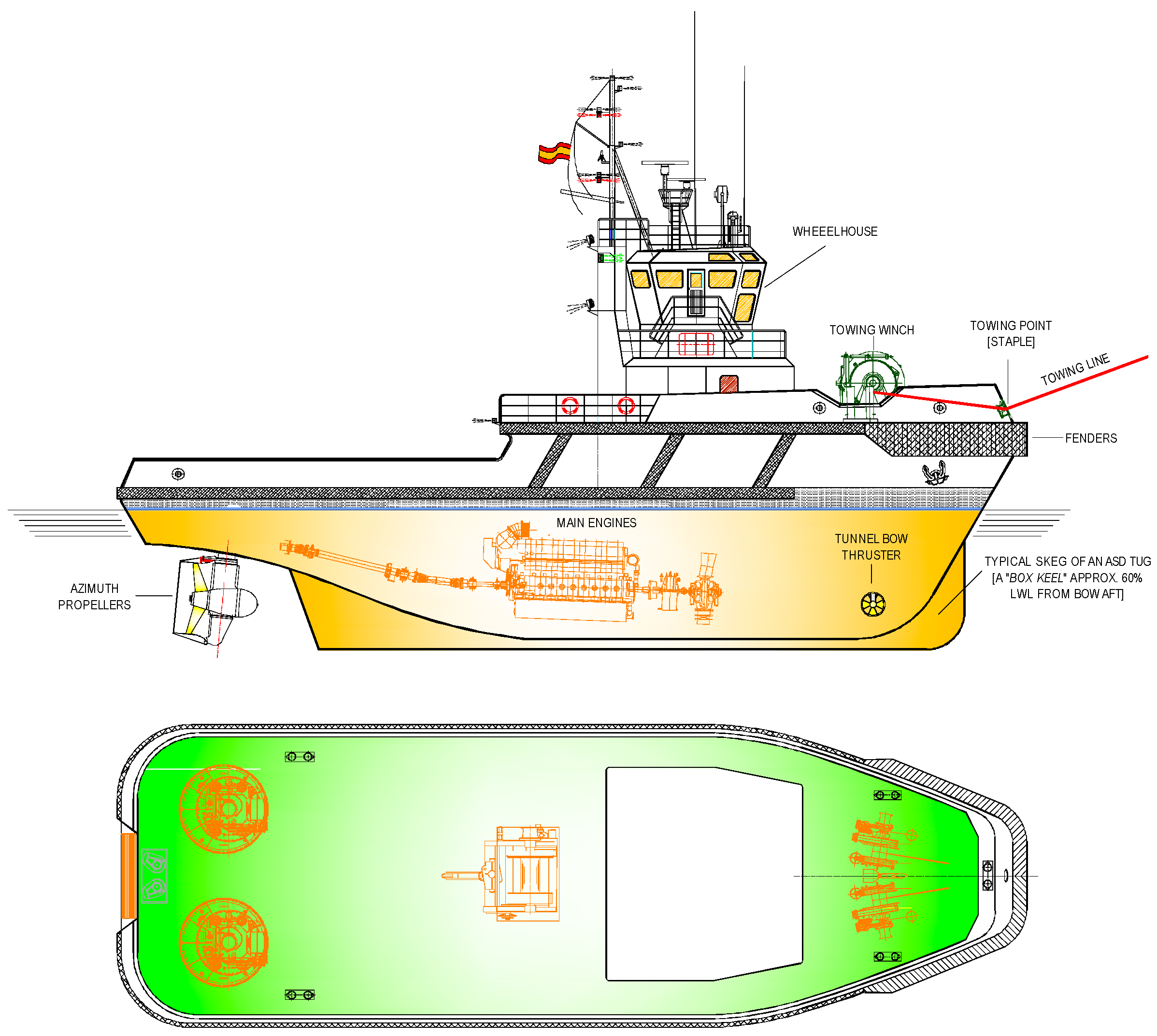
  • Achieving the necessary high stability to withstand the overturning forces produced at yaw or drift angles (angle between the centerline of the tug and the centerline of the assisted ship) [8];
  • Achieving an efficient underwater hull form and skeg capable of generating very high forces with different attack angles against the incoming waterflow. In those situations, the propulsion system is used to maintain this relative position by resisting the hydrodynamic force tendency over the tug to put the towline in line with their centerline [2].
However, the significant relative motions between tug and ship induced by the large waves encountered at many sites have triggered ongoing research to face critical risks that can occur in this condition in order to improve the safety of those maneuvers [1,5].
In these dynamic environments, two recent developments to cope with them deserve special mention: the winch and rope cutting-edge technologies [4,9].
After a brief consideration of the escort towing methods carried out by an Azimuthal Stern Drive (ASD) escort tug, the objective of this paper is to analyze these two new technological advances and to highlight how they can make escort towing maneuvers safer.

2. Escort Towing Methods of an ASD Tug

Basically, there are four escort tug types (the tractor Voith, the Azimuth Tractor Drive (ATD) or tractor Z, the ASD and the Rotor Tug) that carry out their specific escort towing methods [3] (pp. 235–263). As in Baniela and Díaz [2], the methods used by a tractor Voith were analyzed, here, we will show those used by an ASD with the help of figures, adding comments where a specific method needs a particular explanation for this tug.
Figure 1 shows an ASD escort tug. Even though it is common that this type of tug has a winch aft in order to increase its versatility, it is used in ocean towing maneuvers, not in escort or harbor ones where they work “bow first”, with the towline leading to the ship from the forward winch through the staple.
The typical skeg of a modern ASD escort tug, necessary to generate hydrodynamic forces, does not have the high aspect ratio of a tractor tug, for hull geometric reasons, but a box keel located approximately 60% of the waterline length along from the bow aft. This appendix is used to:
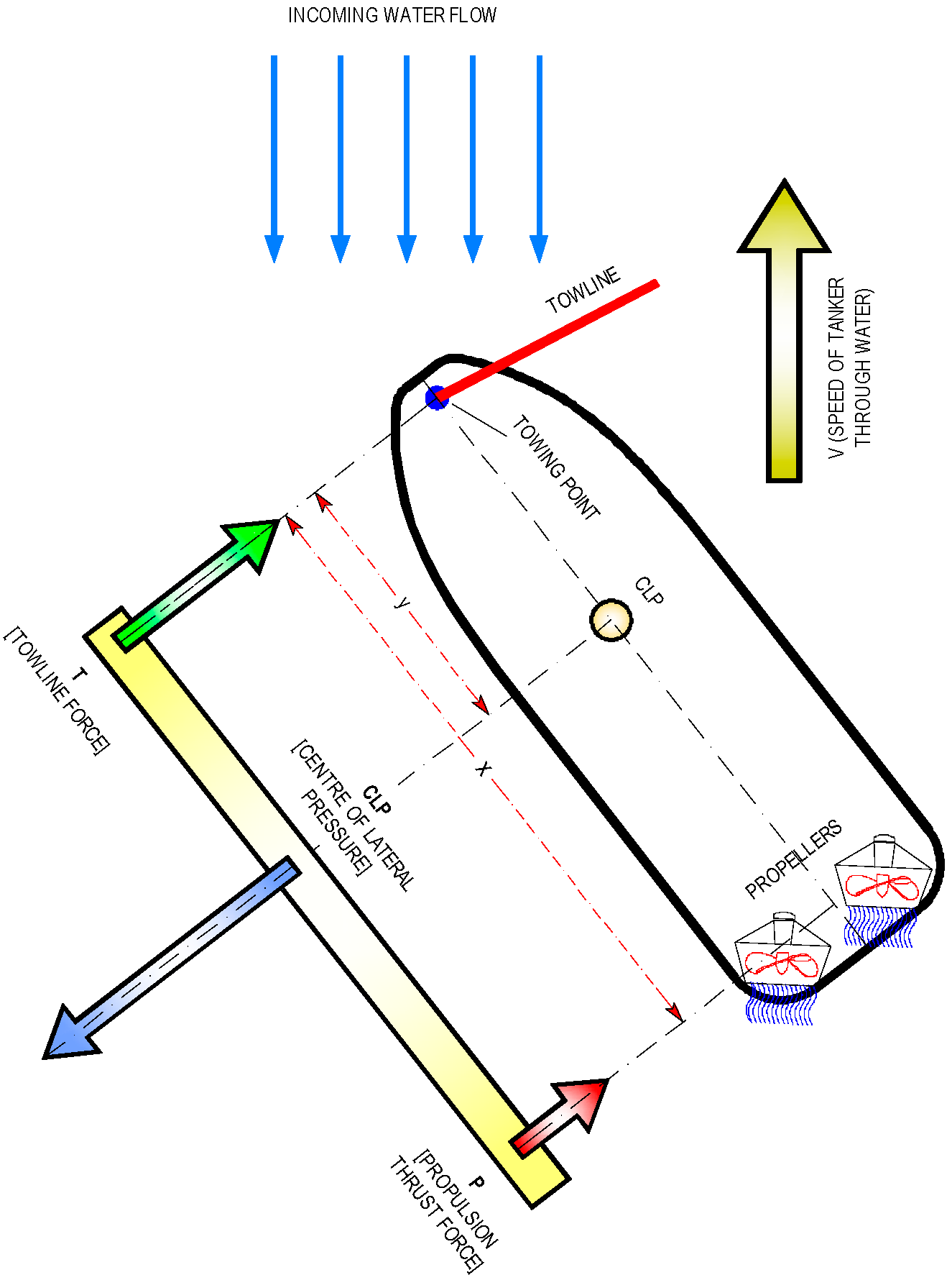
  • Shift the center of lateral pressure (CLP) towards the end opposite the thrusters (i.e., towards forward) in the direction of the attack point of towline force. This is to increase leverage between the CLP and the thrusters so that the thrust necessary for the equilibrium of forces is minimized (Figure 2) [2] (pp. 155–156), and the towline force is maximized with this design option (Figure 1 and Figure 3). However, the CLP should be kept aft of the towing point (the staple) to ensure a “fail-safe” operation so that the towline force will not be prone to overturn the tug in case the propulsion system on the tug fails [10].
  • Increase directional stability.
  • Increase the underwater hull lateral area in the most effective way to improve the hydrodynamic effect at high speeds so that it generates high towline forces in the indirect mode.
In short, there are two methods whose use and forces generated in the towline depend on the speed of the assisted ship a lot:
  • The direct mode, when forces in the towline are generated almost entirely by the thrusters alone and the towline works aligned with the tug’s centerline. This mode is effective at speeds lower than six knots, where the propulsion thrust dominates (around 90% of the towline force).
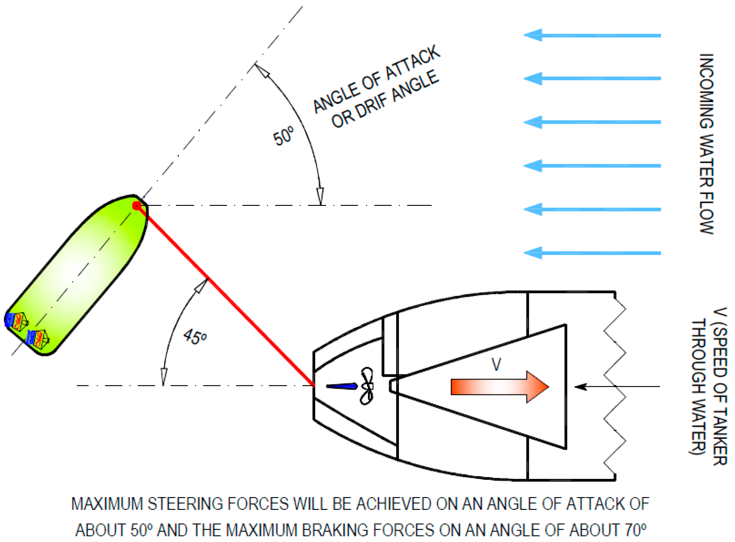
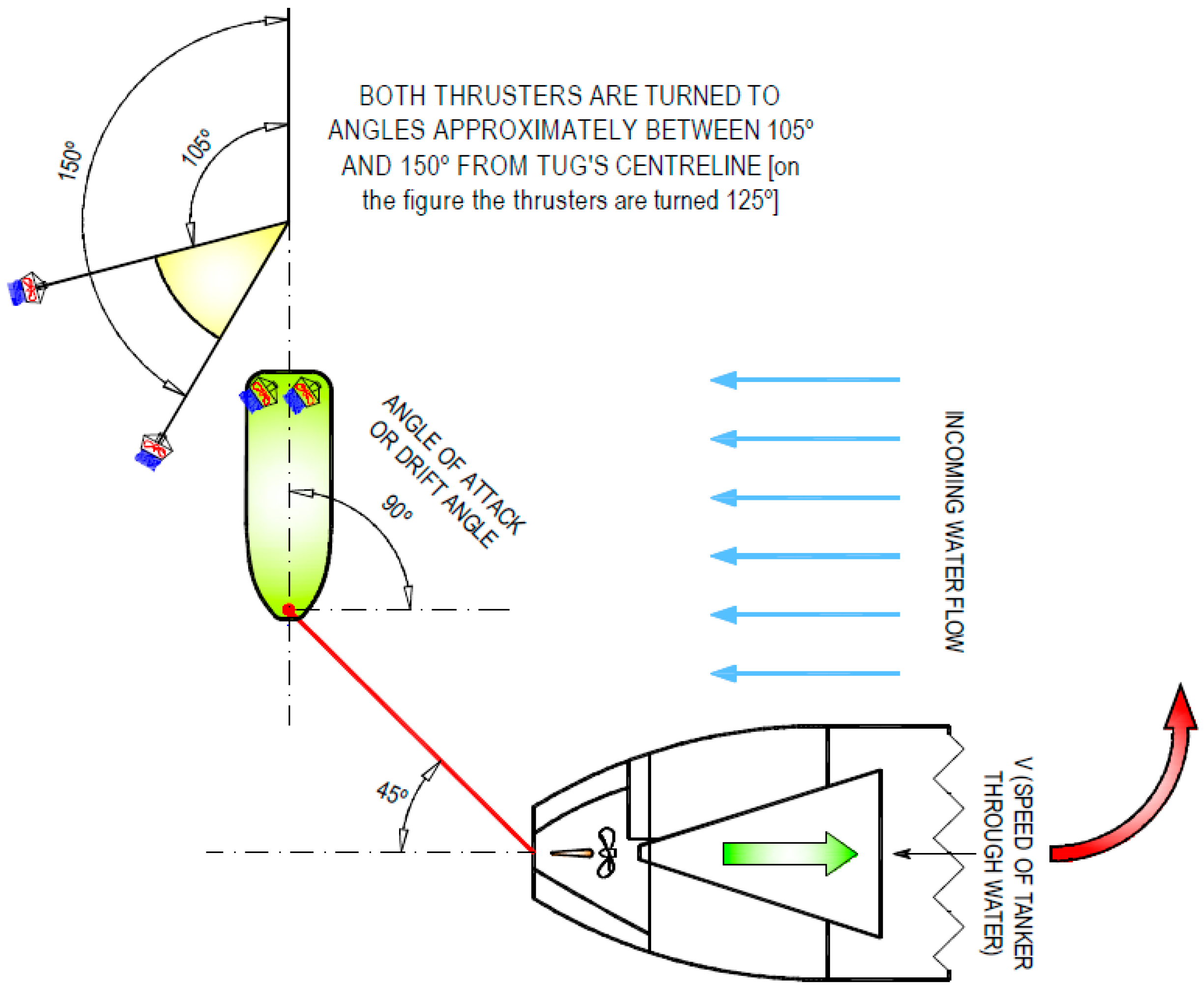
  • The indirect mode, when thrusters are used to adopt an angle of attack against the incoming waterflow and the hydrodynamics of the tug underwater hull and skeg are used to create large braking and steering forces. This mode is effective at speeds higher than eight knots, when hydrodynamic forces from the hull begin to dominate (around 70% of the towline force).
The ASD escort tug will use either method depending on the assistance required—braking or steering and braking—by the escorted ship and their speed.
From an operational point of view, turning the tanker in the most suitable direction is the quickest way to control it, provided that there is sufficient sea room, because its speed is reduced very quickly in this case [11]. This is the reason why the capability of an escort tug to generate maximum steering force is essential. However, the escort tug’s capability to apply maximum braking force becomes necessary in restricted waters when there is not enough room to turn the tanker; therefore, its performance in applying this force in this condition is also important. As a typical escort towing speed is about ten knots, when an emergency occurs, an indirect mode is used first, and as speed is reduced, the escort tug will change to direct mode.

2.1. The Direct Mode

For a mere braking or retard maneuver, direct modes are to be used.
Up to an escorted speed of around six knots, as the engine loads remain at or below the bollard pull condition, the reverse arrest mode (Figure 4) is used. With this configuration, the thrusters work against the relative inflow, being possible with the towline aligned or forming an angle with the ship’s centerline.
At higher speeds, the propellers and main engines will experience an overload condition that increases rapidly, stalling the drives due to a negative flow of water through the propellers, which acts like a brake. Thus, an alternative arrest method has been implemented to counter the effects of negative flow through the propellers of an azimuthing thruster.
From six to eight knots, the tug is in a transitional mode from direct to indirect methods, and the most effective one to control the assisted ship depends on the type of the tug’s propulsion system [10]. In the case of an ASD tug, the transverse arrest mode should be used (Figure 5). As there is no risk of engine overload, braking forces are produced by the thrusters at full power, oriented outward at an angle around 90° with the towline aligned with the ship’s centerline. This force to slow the assisted ship to a speed where reverse arrest may be applied is generated by the transversal acceleration component of the wash (the so-called momentum drag), a phenomenon that is more efficient in propellers with nozzles in azimuthal configuration because the induced speeds are the highest due to the higher rotational speed. With these two direct methods, the escort tug is capable of braking the ship, regardless of speed, to eight knots.

2.2. The Indirect Mode

The indirect mode is used at high speeds (typically between 8 and 10 knots), and depending on the assistance required, the pure indirect method or indirect arrest (Figure 6) (for turning an escorted ship or assisting maneuver) or the combination mode (Figure 7) (to oppose the turning of the ship or opposing maneuver) are used.
In combination mode, the thrusters are turned to angles over 90°, typically between 105° and 150°, and the tug adopts an angle of attack against the incoming waterflow of 90°, thus generating hydrodynamic force on the underwater hull transmitted to the towline (a similar phenomenon as in transverse arrest).

3. Evolution of Escort Tug Winches

To cope with the challenging requirements of escort towing authorities to improve the safety of assistance maneuvers by new winch technologies in dynamic rough water operation environments, the starting point was the conventional winch with tow in the brake, the constant tensioning winch with tow in the drive and, later, the more sophisticated render-recovery winch [12,13].

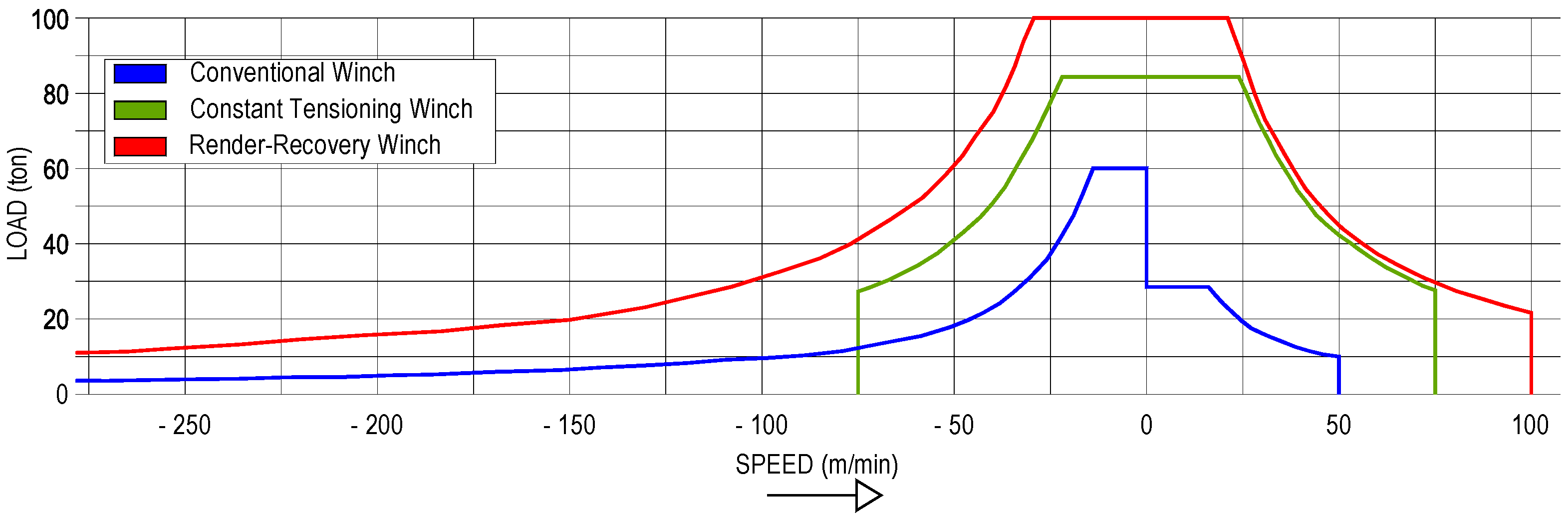
3.1. Former Traditional Winch Technologies: Conventional and Constant Tension Winch

Towing with traditional winches in rough weather conditions can be carried out safely in ocean towing. The towline is a heavy steel wire, and the tug pays out enough line length according to each particular weather condition so that, without needing to modify the towline length, it generates a large catenary that can absorb the dangerous effects of waves. This allows the tug to create line pulls higher than the line pull capacity of the winch without being damaged, even though a classic catenary has some limitations in reducing dynamic loads, with an automatic towing machine also being recommendable to reduce peak tensions [14] (pp. 321–323).
However, this approach is not safe for escort towing assistance and/or unprotected LNG terminals in rough weather conditions generated by wave action. In this case, the distance and catenary are not available to mitigate the high towline loads, and the towline is not a heavy steel wire but a synthetic fiber one [15]. It is the reason why two operational requirements come to light and are causes of concern from the safety point of view:
  • When the tug needs to replace itself regarding the towed vessel, whether it is a conventional or a constant tension winch, it is necessary to pay out enough towline to allow the tug to move to its new position and then pull the line and reset the brake before resuming towing. During the time elapsed in this operation, the towed vessel is allowed to drift uncontrolled for several minutes.
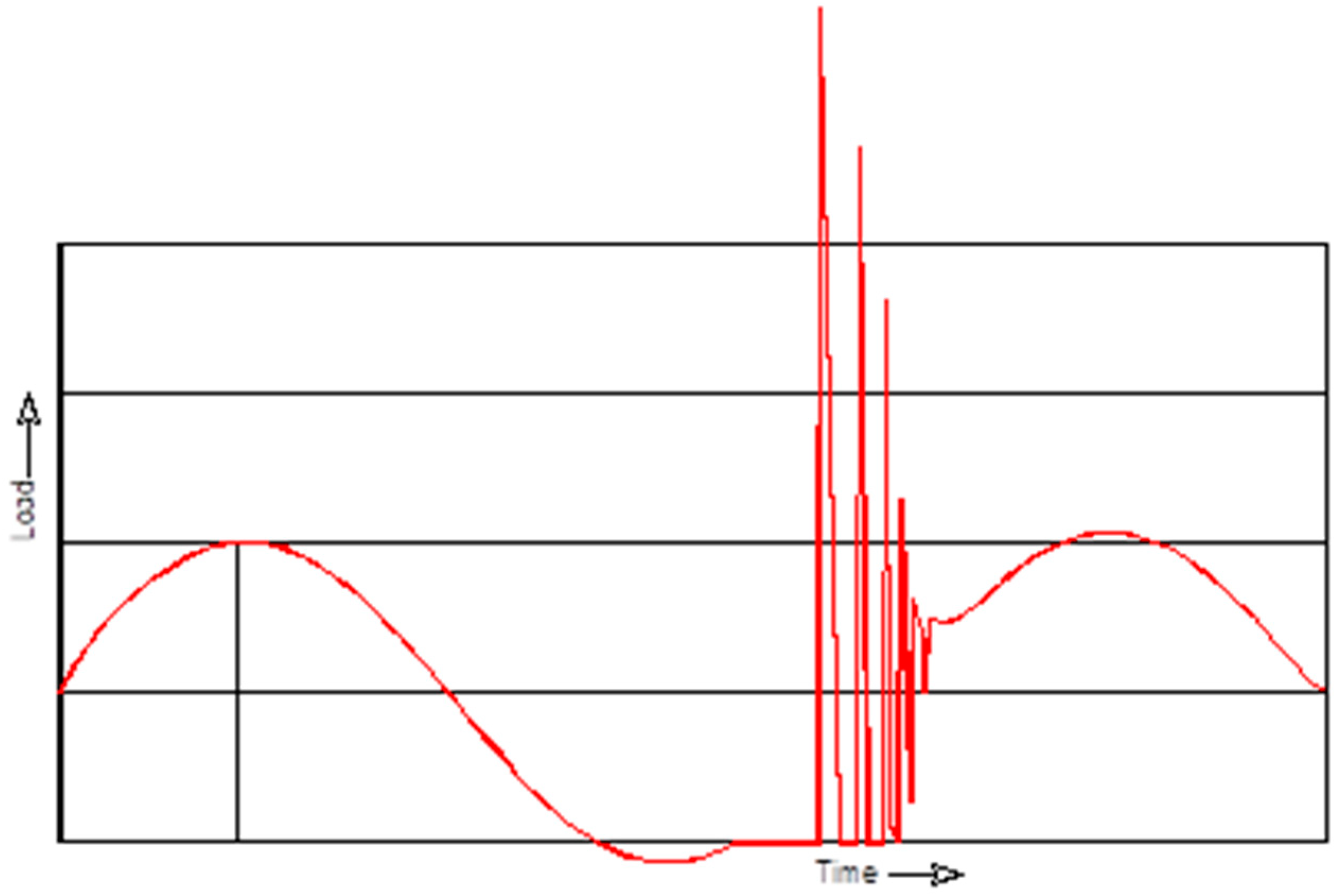
  • The towline length should be considerably shorter, so the catenary and heavy towline are not available to mitigate the high forces produced as a consequence of significant relative motions between the tug and the tow created by waves. Therefore, controlling the high peak loads generated due to working in these dynamic environments is crucial from the safety point of view.
The conventional winch consists of a brake and a drive arrangement characterized by a low pull and a high brake holding capacity [15]. Pull is performed by the drive system, and the speed and force depend on the motor power and gear ratio. Payout is performed by changing the brake force after declutching the drive, and the speed and force are determined by the brake type and their potential cooling system (Figure 8). Towing is performed with the drive system declutched and the brake on, isolating the drive from the towline loads. The brake can be released in an emergency, enabling the winch to rotate freely and, if necessary, detaching the bitter end of the towline for safety reasons. If the towline length needs to be modified, the tug power should be reduced, the clutch engaged, and then, the brake should be applied and the drive declutched to resume the task. The main disadvantages of this winch are:
  • The changes from drive to brake and vice versa are limited by manual control, which makes the operation rather slow;
  • An overload can lead the towline to break;
  • An emergency quick release is not always guaranteed;
  • The winch drive may be damaged in pull/towing mode if peak loads are generated in the towline.
The constant tension winch is a self-tensioning one that automatically adjusts the towline length to maintain it with a pre-arranged tension. Both pull and pay out actions are always operated with the drive on. The speed and force depend on the motor power and gear ratio. The maximum motor speed determines the maximum pull and payout speed (Figure 8). During payout, energy is dissipated through motor cooling.
The main disadvantage of this winch type is that its maximum speed is limited and relatively low. Therefore, it cannot cope with the large dynamic motions generated in waves, which can damage the motor and lead to accidents, as it is not capable of providing enough release speed in emergencies under load.

3.2. The Render-Recovery Winch as a First Step

A great leap forward was achieved with the render–recovery winch (Figure 8), a relatively new development achieved by automating certain functions, especially their capability to shift between brake and drive (to automatically render and recover up to the innate power limits of the winch brake).
This strategy was the start of a major change in philosophy regarding the towline in order to increase the dynamic performance of the towing system to make it safer [4]. This incipient winch technology was conceived, in the words of Allan [16], “[…] to be the safety valve which prevents an overload […]” when dynamic loads are generated in escort towing operations. Until then, in the event of a tow getting into trouble or the tow putting the tug into trouble, the crew had an axe at their disposal to sever the towline, leaving the tow to its own fate.
The term render-recover was used for the first time in 1996 to depict a winch technology that enables dynamic tensioning [12]. It refers to the ability of a winch to pay out or spool out (render) and haul-in (recover) a line without substantial changes in line tension. Due to forces generated by waves and wind action when tug and tow are tethered, the relative motions between them change significantly. This is the reason why render becomes necessary to cope with forces detaching the tug from the tow and to recover to prevent a slack towline. This ability to control the towed ship by automatically maintaining a continuous towline tension was initially developed to permit a tug to replace itself regarding the towed ship during extended tethered transits to lessen both the operator fatigue and wear and tear on the towing system [15]. At first, it was achieved using a hydraulic motor with an intricate pressure control, and later, by a variable frequency AC drive electric motor. As a result of those developments, it is possible both to pull slowly under high loads and to release quickly in an emergency at the expense of a large and expensive drive and brake system. Two drawbacks worth noting include [12,13,17]:
  • The number and intricacy of the components to (dis)connect drive and brake that can be prone to fail to operate properly (reliability);
  • The slow reaction time, as it takes a few seconds due to the mechanical and control systems’ complexity.

4. New High-Performance Dynamic Winches

This term applies to those escort tug winches specially designed to work in rough weather conditions in unprotected waters. The state of the art allows their operating system to be fully automated so that it follows what the waves do to the tug in dynamic environments, without the need for the tug’s skipper to be directly involved. It constitutes the last stage in the improvement of render–recovery winches’ performance, which first appeared in the escort towing world in the mid-1990s and to which we have referred in Section 3.2.
In conditions where wave and wind action often generates extreme relative motions between a tug and tow, the need to design a dynamic winch capable of regulating line tension by automatically anticipating rather than reacting to tension changes in the towline is a must.
To achieve this goal, the so-called “symmetrical” render and recover capability had to be overcome, because the significant power required in dynamic braking or load attenuation is much higher than the inherent haul-in power limits of a typical render–recovery winch drive [15]. As the braking power was not enough to cope with the high peak loads that can be generated in these conditions, other sophisticated means had to be provided.
This provided an opportunity to winch manufacturers and designers to work hard to fill this gap for some time, claimed by authorities and terminal operators in order to give the tug the capability to handle the highly dynamic environmental forces it operates in, making these maneuvers safer. Ongoing research on these demands also contributes to this largely demanded development, with the SAFETUG Joint Industry Project II (JIP II) being the most significant individual instance of research carried out on this item [18,19].
This new winch technology requirement was achieved by leading manufacturers at the end of the 2000s, and it is probably the one that changed more in the escort towing field over the past 15 years [9].
The main purpose of a high-performance winch in dynamic seas is to match the relative motion between a tug and a tanker. In order to do so, the winch must accelerate quickly enough to keep up with the changing directions of inhaul and payout, as well as being capable of maintaining the maximum speed in either direction [20].
In short, this new technology consists of preventing overload and slack towline events induced in escort towing by paying out and retrieving, respectively, with as short of a time delay as possible. Thus, these winches are capable of preventing towline breaking due to overloads by relieving the tension in the towline (render) when a snap load occurs and then recovering the towline to prevent snap loads when tension is generated again after a slack towline event, thus keeping the relative position of tug and tow.

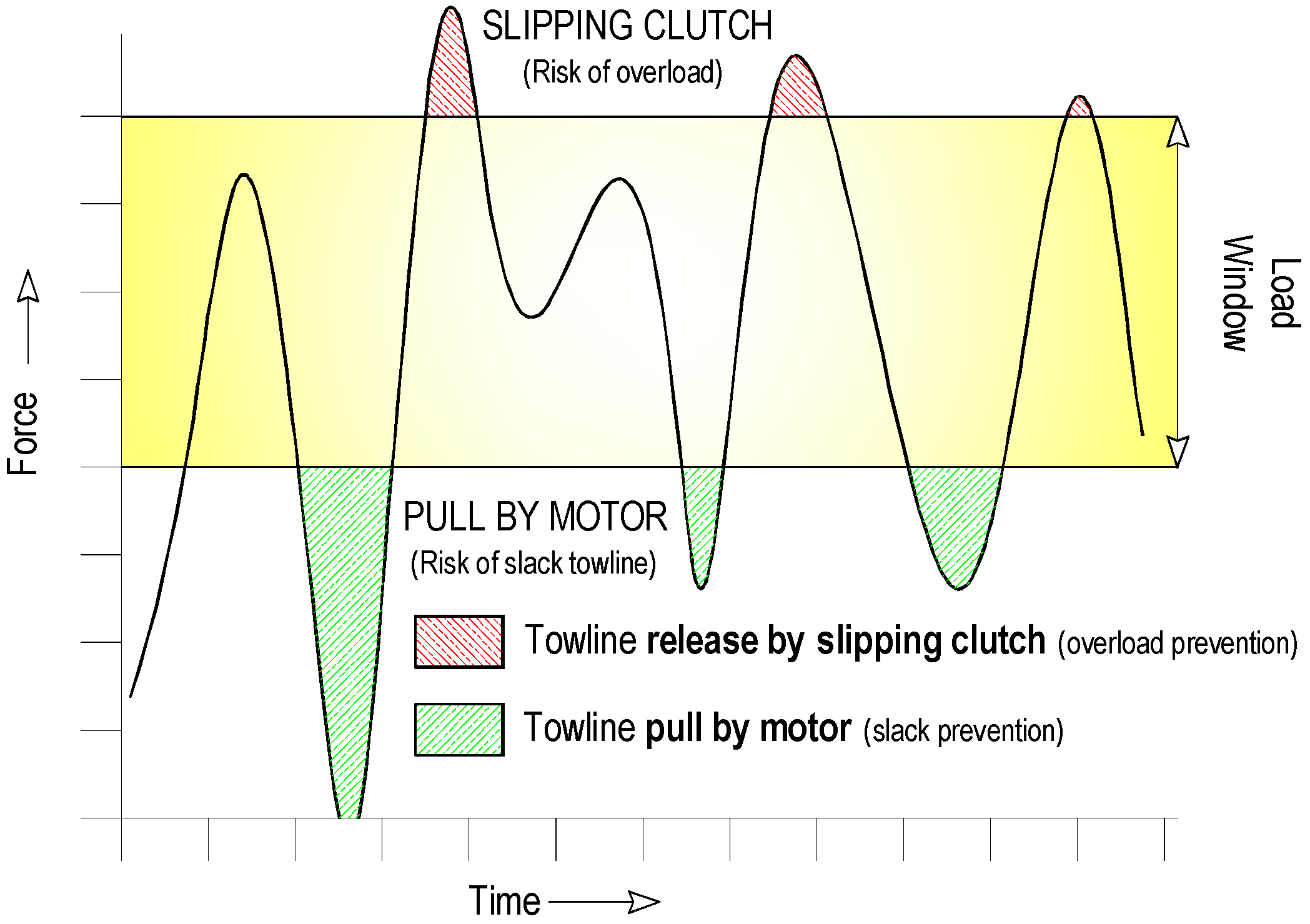
4.1. The Importance of Preventing Slack and Peak Loads in the Towline

When a tug and tow are tethered during dynamic motions in escort towing, they move towards each other and the towline slacks off, followed by opposite motions and a large peak load (a snap load which occurs for a very short period of time).
To obtain an idea of how important it is to keep the towline under constant tension, we only have to look mentally at Newton’s third law. As peak loads occur in very short time, the force generated by the mass of the tug being transmitted and having to be supported by the towline can be up to three times the bollard pull (excluding the slack line events) of the tug. It is the reason why, as de Jong [5] depicts: “the application of very high-strength synthetic towlines, with breaking strengths up to six times the bollard pull, is now commonplace”.
Preventing slack is important because when this mechanical system is modeled and a graph is represented, it is shown how extreme peak loads (Figure 9) follow a relatively short slack period. If parameters are varied, the importance of reducing the slack towline distance is demonstrated, because the snap load force increases roughly with the second power of the slack distance previously generated [17].
By limiting slack line events, a snap load afterwards is also prevented. Thus, the mean pull of the escorted vessel is increased and the risk of breaking the towline due to peak loads generated is reduced.

4.2. Performance of Winches

There is currently an evident trend toward electrically driven winches in this field because they offer the highest overall system efficiency [9] (pp. 21–22), [15], [21] (p. 25) and [22] (p. 1). Some leading winch manufacturers have published their research and empirical data in this field recently, which permits to know how their dynamic winches work and the performance of their associated control systems, such as Markey Manufacturing Ltd., USA—the Asymmetric Render/Recover Winch [15]—and Kraaijeveld BV, Netherlands—the SafeWinch [13].
In general, these winches can automatically maintain constant tension within the limitations of the winch, with a reaction time as short as possible. To prevent a slack towline, the winch can haul in or recover instantaneously and with a suitable speed; to prevent an overload generated by peak loads higher than the winch motor drive capability, they have a slipping clutch to control the excess force, protecting the motor at the same time.
A set point limiting the clutch can be selected, taking into account not only the capability of the tug and its winch to generate towline forces but also the connections, the towline breaking strength, the end fittings and the available strength of towing fittings on the assisted ship [13]. Then, the winch shaves off if any load peaks measured are higher than the set point, allowing the towline to pay out very quickly (within milliseconds) to protect the drive train, and the towline reduces the towline force by reversing the drive train torque enough and the line length until the set point is reached again. In dynamic environments, the force generated by high peak loads often exceeds the maximum horsepower of the winch drive motor, so in this case, reversing the drive train torque should be assisted by a dynamic emergency braking system (typically redundant dynamic high-speed fresh water-cooled disc slip brakes). This is done to dissipate peak loads when the tension exceeds the power capacity of the winch drive until the load lessens to a level where the electric drive can be safely and automatically clutched again [12].
As the maximum towline tension should be adapted to each specific situation by fixing the set point limit, if the master wants to increase the average towline tension, they should increase the minimum low tension from which the winch drive begins to pull automatically [20]. Figure 10 shows the SafeWinch load window from the manufacturer Kraaijeveld BV, in which the overload area is removed by slipping clutch and the slack area by the motor drive pulling the towline in such a way that within an upper and lower tension range (load window), the towline force fluctuates between the overload and slack conditions tackled by the winch.
The term “Asymmetric” to depict the Asymmetric Render/Recover Winch from Markey Manufacturing (Figure 11) is very intuitive, as it refers to the difference between the horsepower rating of the winch drive motor when recovering to prevent slack towline and the higher towline tension that exceeds the power capacity of the electric winch drive in shock load condition. This needs to be dissipated by controlled slip brakes to protect the motor drive when rendering to prevent overloads. Thus, the power of the winch can be reduced in an easier and cheaper way by dissipating energy as heat instead of by fuel with a higher-powered winch motor [1].
From the formula of power, for example, maintaining 75 tons of towline pull at a maximum speed of 1.5 m·s−1 will require a winch of more than 1300 hp:
Power   =   75   tons   force   ×   8896.4   Newtons 1   ton   ×   1.5   m s   =   934 , 126.5   Watts   745.7   Watts 1   hp   =   1342.2   hp
However, as on-board power generation capacity has practical limitations in a tug, to reduce the power requirements of this winch system with its asymmetrical capability, the manufacturer can offer a relatively low power, reducing it to less than 60% (around 750 hp) as it is capable of continuously keeping high towline tension on average in dynamic conditions.
To improve safety, some model winches are equipped with a divided drum and a dual-drive system, where two motor drives are operated in tandem, providing redundancy to the system; if one drive fails, the other goes on working, but at a reduced performance. Emergency stop and quick-release freewheel push buttons are installed on the wheelhouse.
A separately driven spooling gear system (level wind) should be fitted on the winch to reduce the potential for towline damage or breaking by biting into the previously wrapped layer level on the drum under load and getting stuck during deployment, causing excessive wear or damage to the line. A more sophisticated spooling system used by some escort tug operators combines the typical level winding of the two first bedding drum layers tensioned, with a crisscross winding (pulling the towline across the drum to one side and the opposite one) crossing in the middle to form a barrier that impedes the towline from diving into lower layers. This is followed by a level winding of two wraps, after which the crisscross process is repeated again [9].

4.3. Closed Loop Monitoring and Proportional-Integral-Derivative (PID) Control System

Regarding the effective performance of these winches in dynamic environments and without the master actively involved, a safe load control system is vital to achieve an optimum operation because simply assembling their sophisticated components (the clutches, the brakes, the gear train and the large variable frequency electric motors) is not enough [23]. As the adjustments would be almost impossible to achieve by the most trained skipper using hand lever controls, to handle the towline’s constant tension automatically (within the limitations of the winch), very sophisticated software and programing are needed in order to achieve closed loop monitoring and a proportional-integral-derivative (PID) control system [18].
The control system is capable of “reading” the data gathered from sensors integrated in winches, then performing the necessary adjustments in the tension of the brake very quickly or changing the gear ratio and making other adjustments to the process control outputs to respond to the difference between the current measured process variable and the desired setpoint in order to minimize it. In this way, the towline tension and length are optimized. A separate backup controller is usually installed in case the main controller fails. As the motor drive can become declutched in some instances to prevent towline overloads, both the real-time load tension and speed and line scope (length) monitoring sensing should be part of the control system, independent of the motor’s encoder, in order to increase their reliability whether operating the brake or the electric drive [12].

5. The Towline

The towline, being the connection between the ship and escort tug, is of primary importance to operational safety. Therefore, it cannot be considered separately, and a holistic approach becomes necessary nowadays. In recent years, the winch power, as Griffin [22] depicts, has been multiplied sixfold on average over the past 20 years as compared to a doubling of propulsive power in the same time, and towline break strength should be designed accordingly due to the ever-increasing size of assisted ships as the requirements for escort towing forces are higher. Thus, advances in towline technology needed to go hand in hand with new winch technology in order to improve the safety performance of the whole system. This is the main reason why the industry has seen a nearly universal acceptance of high modulus polyethylene (HMPE) synthetic ropes, also known as ultra-high molecular-weight polyethylene (UHMWPE) or high performance polyethylene (HPPE), used successfully in escort towing since the mid-1990s [9,19,22,24].
HMPE lines have very little elongation or stretch under load, and if the winch performance can achieve a dampening effect to control the high tensions generated in dynamic environments, this low-inertia characteristic will give a better load control, which helps to work more safely in these conditions. However, regarding this lack of elongation property, some challenges should be overcome, as their use can lead to snap load effects in the towline of an escort tug working in these harsh conditions greater than in a higher elongation rope as polyester (Figure 12) and they can fail without warning. It is the reason why this type of rope should have the highest possible strength and working load factor [25]. Thus, to cope with those characteristics, two different strategies can be applied in escort towing:
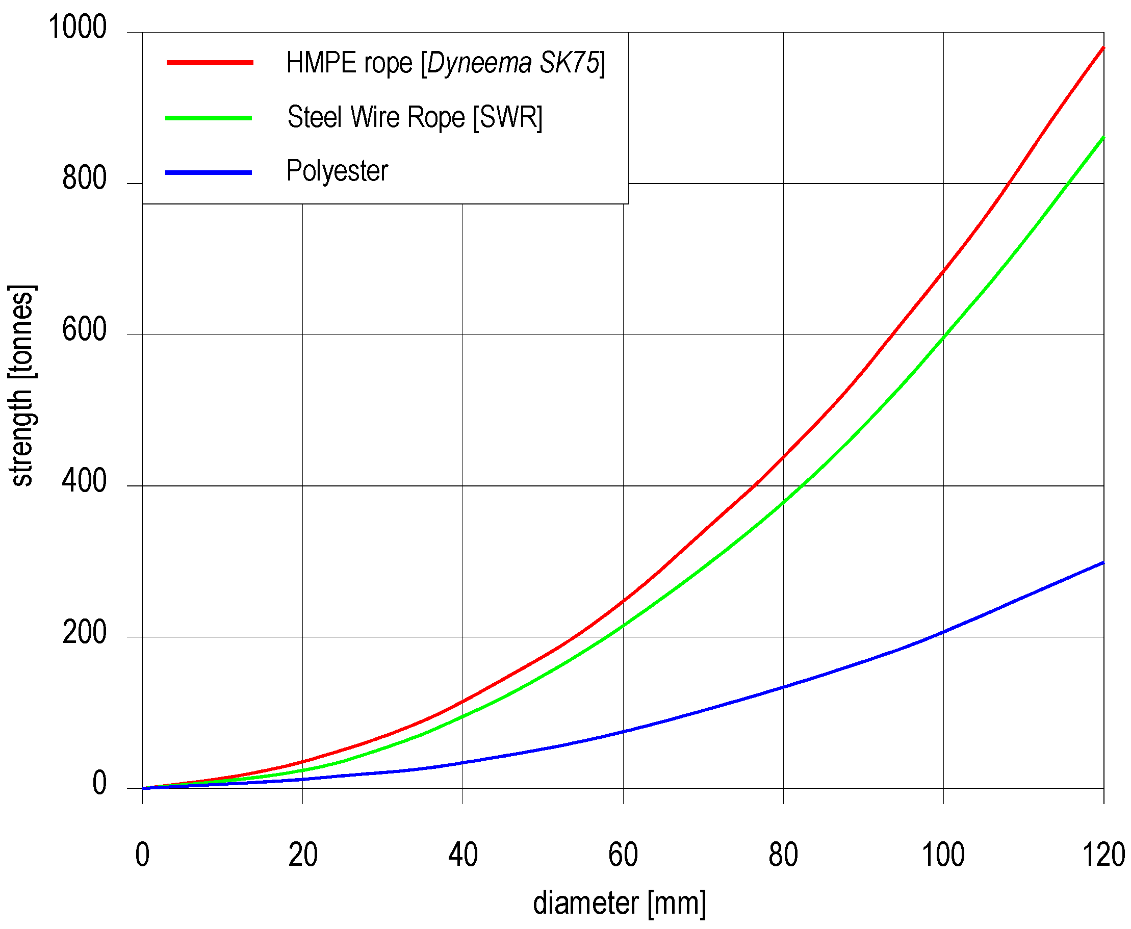
  • As new high performance winches can achieve a dampening effect to control the high tensions generated in dynamic environments, the low-inertia characteristics of HMPE synthetic ropes that have very little elongation or stretch under load give them a better load control, which helps to work more safely. In this case, the best option is the use of an HMPE rope as the total tow rope (monolithic).
  • In compliance with the Class Rules, the use of a less sophisticated winch (in case the tug owner does not embrace the new high performance winch concept) to limit slack line events and snap loads by increasing the elasticity of the towline with a higher elongation one such as polyester can, in comparison, attenuate the higher frequency energy better. Alternatively, an HMPE line connected with a stretcher (a short line of around 20 m in length with higher elasticity—typically polyester) to accommodate the tug motions with relatively little variation in the towline tension can be used. As it was traditionally made, these two options offer additional elasticity at the expense of having a higher risk of towline failure than with the previous strategy.
Obviously, if an escort tug is equipped with a high dynamic winch, to use an HMPE rope without a stretcher is the best option (though some tug operators use it). The reason is that as a stretcher stores much more energy when peak loads are generated, it is released again when the tug moves toward the tanker afterwards in such a way that if elasticity is too high, the tension cannot be controlled and the tug can be catapulted [18].
Although there are small differences among various ropes manufactured depending on their fibers—mainly Spectra® (Honeywell, New York, NY, USA) or Dyneema® (DSM Dyneema B.V., Geleen, The Netherlands)—and how rope manufacturers feature these fibers in their ropes, they have a similar strength to wire rope at the same sizes, but only around 1/6th of the weight, which simplifies their handling. It also floats (enabling tug operations to be much simpler and safer). However, it should be taken into account that if jacketed, they can have a higher density and may sink, depending on the rope’s diameter and the material the jacket is made of [26] (p. 9).
Abrasion is the ability to withstand wear and rupture due to motion against other fibers or rope components within the structure of the towline itself—internal—or by contact with external surfaces—external. As detailed lab simulations and field observations confirmed, it is the dominating factor and most serious threat to the integrity of HMPE ropes used in escort towing, affecting their service life [9,24]. Mitigating it in such a potentially abrasive and demanding environment and protection of the primary working parts of the lines is vital to extend their service life. This is mainly achieved by:
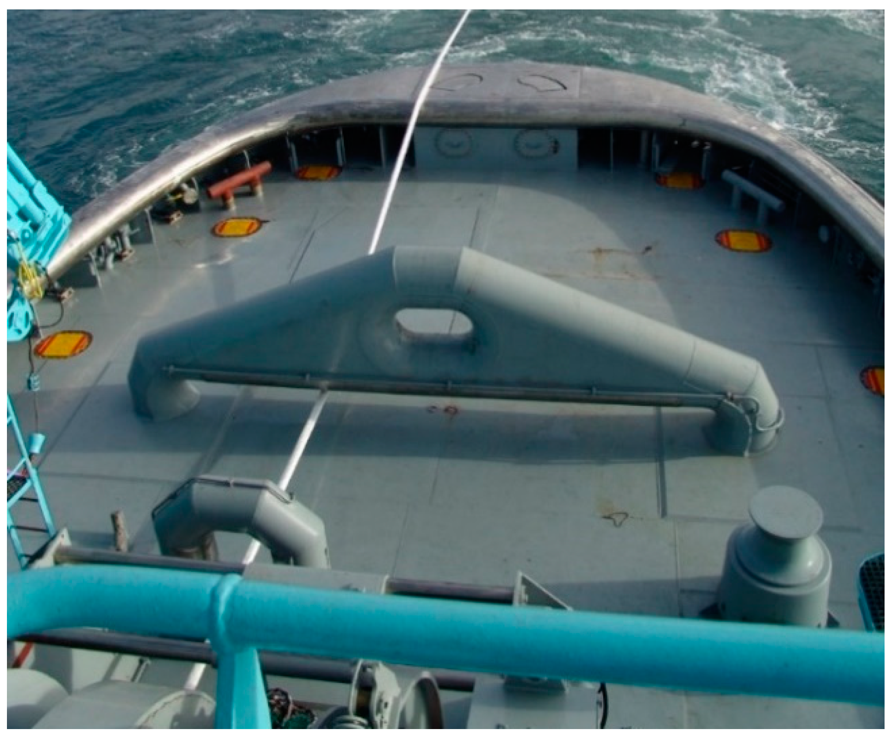
  • Proper deck hardware: To minimize unnecessary abrasion damage, all surfaces in contact with the towline should be smooth (it is recommended to be kept at a maximum roughness of 250 microinches, μ”). Typically, on board the tug, this is achieved by well-designed stainless steel staple and bitts being highly polished (Figure 11) and with a generous bend radius—ideally, the cap rail should be made of stainless steel as well [24]. As the towline leads from the winch drum to the staple and then directly to the tanker, a point of fatigue is generated at the staple, which is exacerbated by the back-and-forth tug motions, which is the reason why water spray cooling is recommendable to dissipate heat due to the friction there [4] (Figure 13).
However, the main source of abrasion leading to failure in the towline, an Achilles’ heel as Arie [27] metaphorically describes, is when it comes into contact with poor fittings (chocks and bitts) on the tanker [9] (p. 5). A good example to follow in order to tackle this drawback is the tanker–escort tug system implemented in Prince William Sound, where tanker fittings should be designed according to the towline force capability of escort tugs deployed there [9,24]. To minimize this potential damage and extend the life of the main towline, a sacrificial pennant—sometimes referred to as pendant or forerunner (a short length of HMPE rope with an eye spliced at both ends)—of the same minimum breaking strength (MBS) is used to endure it [25,28]. The connection between the main towline and the pendant bights is usually made by a “cow hitch” (Figure 14) or by a “spectacle splice” (eye-to-eye connection) [29] (pp. 14–15).
  • Proper chafe protection: The localized abrasion points on the line should be protected by strategic positioning of chafe gear at the appropriate locations (to protect from both internal and external abrasion).
  • Coating technologies developed by manufacturers: Manufacturers are developing coatings at yarn level to reduce internal abrasion enhancing rope wear and snag resistance.
As the coefficient of friction (COF) (or μ) of HMPE ropes is low, to prevent them from slipping on the drum winch, a backer polyester rope of a smaller diameter with a higher COF and that is long enough to cover the core first layer of the drum (sometimes referred to as the “safety layer”) is helpful to mitigate this risk. It should be of sufficient diameter to fit into the bitter end of the winch drum and be spooled under as much tension as possible (to minimize the burying of these working ends of the rope). As the load is largely dissipated in friction while it migrates towards the drum core from the first external wraps, it is not necessary for the backer rope to have the same MBS as the HMPE working line [9,25].
To compensate for the loss of grip due to its low COF, a HMPE towline requires around twice as many wraps in the drum winch than a polyester one to achieve the same holding power. However, on an equal strength by strength basis, its diameter is approximately half, so the drum width can remain the same [30].
Even in relatively moderate sea states, Maritime Research Institute Netherlands (MARIN) found out that, excluding slack line events, towline force can be triple the tug’s bollard pull (BP). To prevent an HMPE towline from breaking in dynamic conditions (according to Allan [9], in extreme sea states, the dynamic loads can exceed ten times the BP), an MBS up to six times the BP is commonplace as a working load factor in order to provide greater safety and to extend the ropes’ service life [5].

6. Towing Winch Design Requirements

Regarding escort towing system design requirements, Classification Societies have had to redefine the design load of towing equipment and associated supporting structures and the design requirements of tow winches, towlines and their guiding fittings in their rules to take into account the dangers of operating in dynamic environments [5,24,31,32].
To accurately define the maximum winch capacity of an escort tug, it is necessary to know its escort towing capability, and then, the final requirements of winch performance can be established accordingly [9,16]. This subject goes beyond the content of this paper; suffice it to say that empirical formulas based on model tests are used where the tug is seen as a spring–mass damper system (Figure 15). The mass is the virtual mass of the tug and the spring is the towline and waves, although the dampening constants of the model to match the wave size and speed are difficult to scale as the behavior of the wave differs with its size, so a margin of error becomes inevitable. Additionally, to achieve specific tailored design requirements to see how much power is needed in the winch, numerical modeling after model or full-scale testing permits to carry out multiple analyses, leading to a more detailed design by considering the behavior of the tug in dynamic environments. This can lead to a more accurate prediction of their performance in these conditions [1,33].
The use of simulation programs [34] to determine the design load, as far as the winch and towline are concerned, is valuable due to the cost and time savings. Its development and reliability is dependent on the accuracy of data collection obtained from previous full-scale tests as well as model tests [5]. It is a complicated task due to the physical complexity of the escort tug phenomenon, where the dynamic variables involved change a lot and very quickly. Based on the design load thus obtained, winch manufacturers are capable of producing a specific winch adapted to the demands of a harbor.

7. Conclusions

The implementation of escort towing at the beginning of the 1990s represented an extraordinary technological challenge not considered until then: to handle the harsh environmental conditions in which an escort tug has to operate. Once the initial design and stability limitations were overcome, there was an additional challenge to be met: the winch and rope technologies. Without those, the best escort tug capabilities would be useless.
When a tug operates in waves, the forces working on the tug increase or decrease the force on the towline, an effect to which we must add the variation of the tug’s heading or the drift angle that changes the balance of forces in presence and, hence, an additional shift in the towline force.
Leading manufacturers achieved the new technology requirement at the end of the 2000s. These winches have the ability to pay out and haul in the towline when shock loads or slack line events occur, respectively, fixing and controlling the towline tension quite accurately. As the line is never slack, the acceleration and deceleration are exactly following what the waves and/or tug skipper are doing to the tug, matching the relative motion between a tug and tanker in dynamic seas. The control system to maintain constant tension is fully automated thanks to measuring the line load and using it as an input to a PID control system; otherwise, the adjustments would be almost impossible to achieve by the most trained skipper using hand lever controls.
Regarding towline technology devised to work in tandem with these new winches, there is no doubt that monolithic HMPE towlines connected by a cow hitch to a sacrificial pendant are the product of choice. Manufacturers working in touch with tug operators developed these very high-strength and lightweight ropes in order to improve their performance, especially their abrasion resistance.
To sum up, the new winch and towline cutting-edge technologies currently permit to carry out escort towing and ship handling assistance in dynamic environments more safely.

Author Contributions

Conceptualization, S.I.-B., J.V.-R. and J.M.P.-C.; methodology, S.I.-B., J.V.-R. and J.M.P.-C.; software, S.I.-B.; formal analysis, S.I.-B., J.V.-R. and J.M.P.-C.; investigation, S.I.-B., J.V.-R. and J.M.P.-C.; resources, S.I.-B., J.V.-R. and J.M.P.-C.; data curation, S.I.-B.; writing—original draft preparation, S.I.-B. and J.V.-R.; writing—review and editing, S.I.-B., J.V.-R. and J.M.P.-C.; visualization, S.I.-B., J.V.-R. and J.M.P.-C.; supervision, S.I.-B.; project administration, S.I.-B., J.V.-R. and J.M.P.-C. All authors have read and agreed to the published version of the manuscript.

Funding

This research received no external funding.

Institutional Review Board Statement

Not applicable.

Informed Consent Statement

Not applicable.

Data Availability Statement

Not applicable.

Conflicts of Interest

The authors declare no conflict of interest.

References

  1. Griffin, B.; Nishimura, G. How to Design a Big New Winch. Design Methodology of Winches for use in Dynamic Seas. Pac. Marit. 2007, 7, 1–4. [Google Scholar]
  2. Baniela, S.I.; Diaz, A.P. The First Escort Tractor Voith Tug with a Bulbous Bow: Analysis and Consequences. J. Navig. 2008, 61, 143–163. [Google Scholar] [CrossRef]
  3. Hensen, H. Tug Use in Port. A Practical Guide; The ABR Company Ltd.: Wiltshire, UK, 2018; pp. 235–263. [Google Scholar]
  4. Braidwood, I.; Allan, R.G. A Risk Profile for Escorted Tankers and Their Resistance to Collision Damage. In Damaged Ship IV; The Royal Institution of Naval Architects: London, UK, 2018; Available online: https://static1.squarespace.com/static/58ffe2e66b8f5b40c0cec664/t/5c8172af971a1811b3000599/1551987382686/Braidwood+Allan+RINA+Damaged+Ships.pdf (accessed on 6 February 2020).
  5. De Jong, G. The Class Answer to the Rapidly Developing Tug Industry. In Proceedings of the International Tug & Salvage Convention and Exhibition, Vancouver, BC, Canada, 7–21 May 2010; pp. 91–112. Available online: http://www.tugmasters.org/wp-content/uploads/2014/07/ITS-2010-The-Class-Answer-to-the-Rapidly-Developing-Tug-Industry-G-de-Jong.pdf (accessed on 11 February 2020).
  6. Allan, R.G. The Evolution of Tug Design through ITS Eyes. In Proceedings of the 25th International Tug, Salvage & OSV Convention and Exhibition, Marseille, France, 25–29 June 2018; Bury, J., Wraight, C., Eds.; The ABR Company Limited: Wiltshire, UK, 2018; pp. 31–49. [Google Scholar]
  7. Rowe, R.W. The Shiphandler’s Guide for Masters and Navigating Officers, Pilots and Tug Masters, 2nd ed.; The Nautical Institute: London, UK, 2000; pp. 129–165. [Google Scholar]
  8. Hensen, H.; Van der Laan, M. Tug Stability: A Practical Guide to Safe Operations, 1st ed.; The ABR Company: Wiltshire, UK, 2016. [Google Scholar]
  9. Allan, R.G. Escort Winch, Towline, and Tether System Analysis. Final Report for Prince William Sound Regional Citizens’ Advisory Council. 2012. Available online: https://www.pwsrcac.org/wp-content/uploads/filebase/programs/maritime_operations/tanker_escorts/escort_winch_towline_and_tether_system_analysis.pdf (accessed on 17 January 2020).
  10. Allan, R.G.; Molyneux, D. Escort Tug Design Alternatives and a Comparison of Their Hydrodynamic Performance. Trans. SNAME 2004, 112, 191–205. Available online: https://nrc-publications.canada.ca/eng/view/ft/?id=515af4f9-1f5e-4728-965b-3070df20cc6e (accessed on 17 January 2020).
  11. Brooks, G.; Slough, S. The Utilization of Escort Tugs in Restricted Waters. Port Technol. Int. 2001, 9, 221–228. [Google Scholar]
  12. Harold, P.D. A Dependable Escort. LNG Industry Magazine—Summer 2011. Available online: https://www.lngindustry.com/magazine/lng-industry/june-2011/ (accessed on 22 November 2019).
  13. van der Laan, M. The Safewinch—Lifeline to Safe Towing. BIMCO Bull. 2008, 103, 46–51. Available online: http://www.imcgroup.nl/downloads/Article_BIMCO_june2008.pdf (accessed on 9 January 2020).
  14. U.S. Navy Towing Manual. SL740-AA-MAN-010. Naval Sea Systems Command; Department of the Navy: Washington, DC, USA, 2002. Available online: https://www.supsalv.org/pdf/towman.pdf (accessed on 9 January 2020).
  15. Griffin, B. Ship Assist and Escort Winches for Dynamic Seas. The ARR Winch for Crowley Maritime Tug RESPONSE. In The 18th International Tug & Salvage Convention; Smith, A., Ed.; The ABR Company Limited: Wiltshire, UK, 2004; pp. 119–126. [Google Scholar]
  16. Allan, R.G. The State of Tug Safety Today. In Proceedings of the 25th International Tug, Salvage & OSV Convention and Exhibition, Marseille, France, 25–29 June 2018; Bury, J., Wraight, C., Eds.; The ABR Company Limited: Wiltshire, UK, 2016; pp. 25–36. Available online: http://seaways.net.au/wp-content/uploads/2018/07/The-State-of-Tug-Safety-Today.pdf (accessed on 17 January 2020).
  17. van der Laan, M.; Kraaijeveld, K. SafeWinch Tackles Slack Wires and Peak Loads. In Proceedings of the Tugnology’07 Conference, Southampton, UK, 11–12 June 2007; Available online: http://www.imcgroup.nl/downloads/Safewinch%20Article%20Tugnology.pdf (accessed on 9 January 2020).
  18. de Jong, J.H.; Armaoglu, E.; Bron, I.G.L.; van den Berg, J.; Grin, R.A.; ten Hove, D. Ship Assist in Fully Exposed Conditions—Joint Industry Project SAFETUG II. In Proceedings of the International Tug & Salvage Convention and Exhibition, Vancouver, BC, Canada, 7–21 May 2010; Gorman, D., Ed.; The ABR Company Limited: Wiltshire, UK, 2010; pp. 81–90. Available online: https://towmasters.files.wordpress.com/2010/09/its4_ship_assist_in_fully_exposed_conditions.pdf (accessed on 11 February 2020).
  19. Vlašic, D. Tug Safety: Some Conclusions from the SAFETY II Research Programme; Lloyd’s Register Technology Days; Paper 6; Lloyds: London, UK, 2011; pp. 63–73. [Google Scholar]
  20. Griffin, B.; Nishimura, G. High Performance Winches for High Performance Tugs—Winch and HMPE Rope Limitations. In Proceedings of the Tugnology’09 Conference, Amsterdam, The Netherlands, 19–20 May 2009. [Google Scholar]
  21. Griffin, B.; Dempke, B. High Performance Winches. Pac. Marit. 2006, 7, 22–25. [Google Scholar]
  22. Griffin, B. Commercial Marine Deck Machinery—30 Years of Change. Pac. Marit. 2009, 7, 1–3. [Google Scholar]
  23. Langerak, H. Escort Tug—Tow Winch Load Control. In Proceedings of the Tugnology’09 Conference, Amsterdam, The Netherlands, 19–20 May 2009. [Google Scholar]
  24. Crump, T.; Volpenhein, K.; Sherman, D.; Chou, R. Abrasion and Fibre Fatigue in High-Performance Synthetic Ropes for Ship Escort & Berthing. In The 20th International Tug & Salvage Convention; Gorman, D., Ed.; The ABR Company Limited: Wiltshire, UK, 2008; pp. 205–212. Available online: http://www.tugmasters.org/wp-content/uploads/2014/07/Terrycrump.pdf (accessed on 11 February 2020).
  25. Underhill, R. Fitting Fibre Rope to the Towing Winch—A Guideline. In Proceedings of the Tugnology’09 Conference, Amsterdam, The Netherlands, 19–20 May 2009; Available online: https://www.tugmasters.org/wp-content/uploads/2014/07/Fittingfibrerope.pdf (accessed on 9 January 2020).
  26. OCIMF. Guide to Purchasing High Modulus Synthetic Fibre Mooring Lines, 1st ed.; OCIMF and SIGTTO: London, UK, 2014; Available online: https://www.ocimf.org/media/53251/guide-to-purchasing-high-modulus-synthetic-fibre-mooring-lines-februar.pdf (accessed on 9 January 2020).
  27. Arie, N. Ships’ Deck Fittings Utilised for Towage. In Proceedings of the 25th International Tug, Salvage & OSV Convention and Exhibition, Marseille, France, 25–29 June 2018; Bury, J., Wraight, C., Eds.; The ABR Company Limited: Wiltshire, UK, 2018; pp. 103–116. Available online: https://www.chirpmaritime.org/wp-content/uploads/2018/12/Ship-Fittings-by-A-Nygh.pdf (accessed on 17 January 2020).
  28. Wardenier, S. Improved Efficiency in Connecting Tugs to Vessels. In Proceedings of the Tugnology’11 Conference, Antwerp, Belgium, 17–18 May 2011. [Google Scholar]
  29. OCIMF. Static Towing Assembly Guidelines (STAG), 1st ed.; The Oil Companies International Marine Forum (OCIMF): London, UK, 2020; Available online: https://www.ocimf.org/media/154730/Static-Towing-Assembly-Guidelines-2020.pdf (accessed on 5 October 2020).
  30. Griffin, B. Deck Machinery Mooring Issues. Pac. Marit. 2003, 7, 25–28. [Google Scholar]
  31. BV. Rules for the Classification of Steel Ships (NR467); Part E Service Notations for Offshore Service Vessels and Tugs [NR467.E1 DT R03 E]: CHAPTER 1 TUGS. Section 3 Hull Structure. 3 Additional Requirements for Escort Tugs. 3.2 Equipment for Escort Operations; Bureau Veritas: Paris, France, 2020; pp. 46–48. Available online: https://marine-offshore.bureauveritas.com/nr467-rules-classification-steel-ships (accessed on 5 October 2020).
  32. DNV GL. Rules for Classification; Part 5 Ship types. Chapter 10 Vessels for special operations. SECTION 11 TUGS AND ESCORT VESSELS. 6 Additional Requirements for Escort Tugs. 6.3 Equipment. 6.3.1 Towing Winch; DNV GL: Oslo, Norway, 2020; Available online: https://rules.dnvgl.com/docs/pdf/xtra/dnvgl-class/2020-11/dnvgl-class_2020-11.zip (accessed on 5 October 2020).
  33. Griffin, B.; Van Buskirk, J.; Greene, R.W. Methodology for the Selection of Winches and Ropes for Assist and Escort Tugs in Dynamic Seas. In Proceedings of the Tugnology’07 Conference, Southampton, UK, 11–12 June 2007; Available online: http://seaways.net.au/wp-content/uploads/2015/12/Escort-tugs-BarryGriffin.pdf (accessed on 14 November 2020).
  34. Hensen, H. Ship Bridge Simulators: A Project Handbook, 1st ed.; The Nautical Institute: London, UK, 1999. [Google Scholar]
Figure 1. A typical Azimuthal Stern Drive (ASD) escort tug. Drawing: Authors.
Applmech 02 00004 g001
Figure 2. The athwartships force balance of an ASD escort tug using the pure indirect method. Drawing: Authors.
Applmech 02 00004 g002
Figure 3. (a,b) The ASD escort tug “Costante Neri” delivered in September 2009 by Gondán Shipyard, S.A. (Spain), to the owner Fratelli Neri S.p.A. (Italy). Photo: Authors.
Applmech 02 00004 g003
Figure 4. Direct reverse arrest mode by an ASD escort tug (0–6 knots). Drawing: Authors.
Applmech 02 00004 g004
Figure 5. Transverse arrest mode by an ASD escort tug (6–8 knots). A transitional mode between direct and indirect methods. Drawing: Authors.
Applmech 02 00004 g005
Figure 6. Pure indirect escort towing method by an ASD. Drawing: Authors.
Applmech 02 00004 g006
Figure 7. Combination mode towing method by an ASD (7–10 knots). Drawing: Authors.
Applmech 02 00004 g007
Figure 8. Typical parameters of conventional, constant tensioning and render-recovery winches [17]. Drawing: Authors.
Applmech 02 00004 g008
Figure 9. Slack towline followed by a large peak load (≈2.5 × Amplitude) [17]. Drawing: Authors.
Applmech 02 00004 g009
Figure 10. Typical towline load variations and SafeWinch behavior in dynamic conditions [17]. Drawing: Authors.
Applmech 02 00004 g010
Figure 11. Asymmetric Render/Recover® Hawser Electric Winch model DESDF-48-200 from Markey Machinery.
Applmech 02 00004 g011
Figure 12. Rope properties, strength versus diameter of different lines as per Samson Rope manufacturer. Drawing: Authors.
Applmech 02 00004 g012
Figure 13. Wide staple of Escort Voith Water Tractor Tug “Tenax” with water spray cooling for escort towing with a high modulus polyethylene (HMPE) towline. The contact surfaces of both the staple and all around the cap rail are made of a highly polished stainless steel. Photo: Authors.
Applmech 02 00004 g013
Figure 14. Cow hitch connecting HMPE towline to a sacrificial pendant. Drawing: Authors.
Applmech 02 00004 g014
Figure 15. Analogy of an escort tug in a dynamic environment to a mechanical spring-mass damper system. Drawing: Authors.
Applmech 02 00004 g015
Publisher’s Note: MDPI stays neutral with regard to jurisdictional claims in published maps and institutional affiliations.

