Free Vibration Analysis of Rotating Beams Based on the Modified Couple Stress Theory and Coupled Displacement Field


1
Mechanical Engineering Department, University of Kentucky, Lexington, KY 40506, USA
2
Institute of Research for Technology Development (IR4TD), University of Kentucky, Lexington, KY 40506, USA
*
Author to whom correspondence should be addressed.
Appl. Mech. 2021, 2(2), 226-238; https://0-doi-org.brum.beds.ac.uk/10.3390/applmech2020014
Submission received: 6 March 2021
/
Revised: 9 April 2021
/
Accepted: 13 April 2021
/
Published: 16 April 2021
(This article belongs to the Special Issue Damage Sensing in Composites for Structural Health Monitoring)
Abstract
:In this paper, transverse vibration analysis of rotating micro-beam is investigated based on the modified couple stress theory. The simply-supported micro-beam is modeled utilizing Euler-Bernoulli and Timoshenko beam theories. The system is rotating around a fixed axis perpendicular to the axial direction of the beam. For the first time, displacement filed is introduced as a coupled field to the translational field. In other words, the mentioned rotational displacement field is expressed as a proportional function of translational displacement field using first (axial), second (lateral), and third (angular or rotational) velocity factors. Utilizing Hamilton’s approach as a variational method, dynamic-vibration equations of motion of the proposed model are derived. Galerkin’s method is adopted to solve the equation corresponding to the Euler–Bernoulli and Timoshenko beams. For the case considering shear deformation effects, Navier method is chosen. For evaluation of current results and models, they are compared with those available at the benchmark. In this paper; effects of slenderness ratio, axial, lateral, and angular velocity factors, and rotations of the beam on the frequency are reported. Based on the results presented, mentioned factors should be counted in the analysis and design of such rotating micro-systems.
1. Introduction
Through the past decade, micro-electro-mechanical-system (MEMS) technology has been attractive to a significant number of researchers from Mechanical, Electrical, Chemical, and Biomedical engineering. The mentioned technology refers to the miniaturized mechanical and electrical elements manufactured by micro-fabrication techniques. Most significant applications of MEMS technology include micro-sensors, microscale safety devices, micro-actuators, micro-resonators, energy harvesting, optical metamaterial applications, and atomic force microscopes [1,2,3,4,5,6,7,8,9,10,11,12].
To present the industrial community with perfect prototypes, static and dynamic analysis should be applied on ideal models. It proves that for such small-scaled devices, classical mechanics does not end into accurate results. However; using non-classical theories, size-dependency phenomena are captured, and more accurate results and analysis is achievable [13]. One the most useable theories is the modified couple stress theory (MCST). In this theory, a single material length scale parameter captures the relation between symmetric part of the rotational gradient and the couple stress tensor which leads to size-dependency of the theory. Besides to equilibrium equations of forces and moments, an additional equilibrium equation of moments of couples is considered in MCST. MCST is also highly popular among researchers since it has only one length scale parameter [14].
Based on the mentioned non-classical theory, several researchers have studied static and dynamic analysis of micro and nano-scaled systems. Vibration analysis of a thermally-stressed Timoshenko beam is studied by Ghadiri and Shafiei [15]. The proposed micro-beam model is under load which is resulted by rotation effects of the beam. Results of this study disclose the impact of material gradation and variations, boundary conditions, angular velocity and thermal stress over oscillatory analysis of the mentioned systems. The flutter mechanism of Timoshenko beams in supersonic flows is studied by Qian et al. [16], where they derived the PDE equation system for the mentioned fluctuations by analyzing the finite section of the beam. Vibration analysis of small-scaled shells according to the first order shear deformation model of shells is announced by Beni et al. [17]. They have shown the importance of size-dependency through analysis. Thai et al. [18] investigated the static, bending, and vibration analysis of a Timoshenko-beam. They have highlighted the increment of natural frequency and stiffness with small-scaled systems in comparison to macro-systems. Bending and vibration analysis of a micro-beam considering position of the neutral axis is carried out by Al-Basyouni et al. [19]. They suggested a variable material length scale parameter. Akbas et al. [20] reported the impact of edge cracks via mutations in vibrational behavior. They proposed a cracked model accounting material gradation. The impacts of crack depth and material distribution and beam length; over resonant and natural frequencies are discussed. Yin et al. [21] presented a new a new isogeometric Timoshenko beam model using modified couple stress theory and surface elasticity theory incorporating microstructures and the energy cells. They concluded that both the microstructure and the surface energy effects need to be considered for a thin beam at the same time and explained the size-dependent behavior of such beams. Nateghi and Salamat-talab [22] studied buckling and vibration analysis of micro-beams under thermal stresses according to the first-order shearing effects theory. Authors adopted differential quadrature method (DQM) to state the importance of material length scale parameter, thermal stress and temperature fluctuations, and poison’s ratio over static and dynamic behavior of electro-mechanical systems. Ke et al. [23] conducted a research studying the buckling and vibration analysis of small-sized Timoshenko-beam and accounting the shearing effects. In this study, the Mori-Tanaka distribution profile is utilized for material distributions. Babaei and Ahmadi [24] studied the dynamic responses of a beam-shape MEMS element having non-homogenous material properties. Yilmaz and Orhan [25] presented an analytical study to predict deflection and stiffness of rectangular notch micro cantilever beam. Babaei et al. [26] reported free vibration analysis of nonlocal beam undergoing thermal stresses. Changing material length scale parameter effects upon the dynamic-vibration analysis of Timoshenko beam is studied by Babaei and Rahmani [27]. Sur et al. [28] presented a computationally-efficient model to predict the dynamic response of a homogenous, transversely isotropic, thermoelastic micro-beam, under a time-dependent thermal load. Babaei et al. [29] carried out the vibrational analysis of a micro-Euler–Bernoulli beam, in which thermo-mechanical properties vary through thickness direction. They proposed the model based on the modified couple stress theory. Material properties are changing based on the power law. Further to the mentioned papers, rotation-based analysis of the micro-systems is a hot topic due to the applications in industry and biology. Ilkhani and Hosseini-Hashemi [30] reported vibration and stability analysis of rotating micro-beams. Results of this paper state that non-classical material length scale parameter, tangential load value and the corresponding direction of the load, and the value of angular velocity are the most influencing factors through prediction of the behavior of the system. Shafiei et al. [31] studied vibration analysis of a rotary micro-beam with non-uniform cross section. Based on the Euler–Bernoulli beam theory, the non-uniform tapered structure is under axial load which is caused by rotation. The impressions of angular velocity, geometric characteristics of the beam, non-classical parameter, and rate of cross-section variations upon the mode shape functions and frequencies are reported. Dynamic and vibration analysis of small-scaled systems have attracted more research efforts in this course [32,33,34,35].
Sarparast and Ebrahimi-Mamghani [36] studied the rotating beams effects considering the foundation forcing impositions. Rotating rods analysis under the effects of axial loading is reported by Ebrahimi-Mamghani et al. [37]. Ebrahimi and Mokhtari [38] investigated vibration analysis of rotating porous micro-beam. Material properties of the beam vary based on the power of law through thickness direction. They showed the importance of the rotational speed accompanying the material distribution profile on the analysis. Chen et al. [39] studied vibration analysis of a tapered Timoshenko beam based on the iteration method. Effects of the rotational speed and rate of the cross section change on the dynamic analysis are reported. Babaei [12] investigated the forced vibration analysis of small-scaled rods subject to impulse, step and ramp inputs. Babaei and Yang [40] conducted a research analyzing the vibration analysis of a rotating rod using the coupled displacement filed theory. They showed the significance of the angular velocity and rotations of the system. According to the presented literature review, there is not any published research work about vibration analysis of rotating micro-beams based on the coupled displacement filed and accounting the shearing effects in the course of Timoshenko beam model. Thus, for the first time in this paper, both thick beams (Timoshenko) and thin beams (Euler–Bernoulli) models are studied and a comprehensive analysis is accomplished related to the effects of shearing effects and beam slenderness ratios. In other words, for the first time the angular velocity of the beam is supposed to be a proportional function of all displacement and shearing strain parameters. To do this, the angular displacement is function of: axial displacement, lateral displacement, and the shearing strain resulted from the thick beam theories.
The proposed models with simply-supported (pinned–pinned) boundary conditions undergo various rotational (angular) speeds. Hamilton’s variational approach is used to derive the dynamic-vibration equations and for solution procedure, Galerkin’s approach and Navier method are used. The proposed model is highly applicable to overcome the limitations of efficient MEMS energy harvesters. In other words, with small-scaled energy harvesters, the excitation frequency and the resonant frequency of the system end up in discrepancy. Decreasing the resonant frequency is the solution to this issue which will end in more efficient energy harvesters. The proposed model studies the effect of axial and rotating (shearing strain) parameters’ effects over the resonant frequency variations. Such model extends the former resonant frequency adjusters using only the lateral parameter and introduces more options in this regard by means of thicker beams.
2. Fundamentals of the Modified Couple Stress Theory (MCST)
Modified couple stress theory states that Cauchy stress tensor multiplied by Cauchy strain tensor; and couple stress tensor conjugated with the curvature tensor, form strain energy density function. Accordingly, strain energy for an isotropic linear elastic material is as follows (Babaei et al. [13]):
where, are Cauchy stress, deviatoric part of couple stress, Cauchy strain and symmetric part of curvature tensors. These tensors are defined as follows [3]:
where, means gradient (), is displacement vector, is non-classical material length scale parameter, is shear modulus of rigidity, shows Lame’s constant, shows identity tensor, and is rotation vector.
3. Kinematic Relations
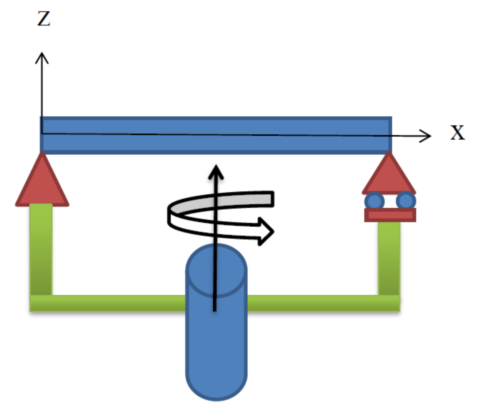
In this section, a simply-supported (pinned-pinned) beam is considered as shown in Figure 1.
The beam is fixed by pines to the bottom plane, and this plane is rotating around the fixed axis. Beam has length , thickness and width . Based on the Euler–Bernoulli beam theory (EBBT), longitudinal (axial) displacement of any point on the neutral axis is:
For Timoshenko beam (TBT), axial displacement is set forth to consider the shear deformations:
For both beam theories mentioned above, displacements through thickness and width of the beam are:
In which, shows the axial displacement, is the lateral displacement function, and is time.
It is good to note that for EBBT, rotation is equal to the partial derivation of lateral displacement (), while for TBT these two values are not equal to each other and their difference is shear strain (). Using Equations (2c,d) and (3), following strain and stress elements for EBBT and TBT are obtained:
Substituting Equation (4a–d) into the Equation (1), strain energy due to the infinitesimal deformations of a Euler–Bernoulli micro-beam is obtained:
Strain energy for the Timoshenko micro-beam is:
Since we use variational approach, variations of the energy terms should be obtained. By integration by parts from Equation (5a,b); and producing following cross section area and second moment of inertia of the cross section, we have:
Kinetic energy of the Euler–Bernoulli and Timoshenko micro-beams can be expressed in the following order:
Previously, researchers considered the proportional function containing only the lateral displacement (xφ(x,z,t) = βw(x,t)). However, in this paper for the first time, a comprehensive model is proposed in which the angular displacement (φ(x,z,t)) is expressed in terms of a proportional function of axial and lateral displacement and rotational displacement which is related to the shearing strain. Such a comprehensive enables us to study the effects of other displacement functions besides to only the lateral displacement function:
Angular displacement () is expressed in terms of axial and lateral displacement and rotational displacement:
As for the Hamilton’s approach, we need to obtain the integration of the difference of kinetic and strain energy terms within a short time interval:
After some mathematical operations and integration by parts, following dynamic-vibration equations are obtained:
For Euler–Bernoulli beam (EBBT):
For Timoshenko beam (TBT):
Corresponding boundary conditions for the simply-supported beam are as follows:
4. Numerical Solution
4.1. Solution Approach for Euler–Bernoulli Beam
For the case of free vibrations without viscous damping, we can consider lateral displacement in the following form:
In the harmonic expression for , represents natural frequency and . Substituting Equation (18) into Equation (15) leads to the following:
Equation (19) can be solved by means Galerkin’s method. Based on the Galerkin’s approach, displacement function is replaced by series of trial (admissible) functions () multiplied by unknown coefficients ().
The mentioned admissible functions should satisfy the general boundary conditions of the system. For the pinned–pinned boundary conditions, sinusoidal trial functions are suggested:
Substituting Equations (20) and (21) into Equation (19), then multiplying by and finally integrating over the length of the beam leads to the following equation:
Considering the orthogonality of the harmonic (periodic) functions over a full period, and by some mathematical operations Equation (22) can be rewritten in the following form in which can be solved by MATLAB:
4.2. Solution Approach for Timoshenko Beam
For the presented Timoshenko micro-beam model, Navier solution approach is used. Based on the mentioned approximate method, lateral, axial, and rotational displacements of the beam can be substituted with following series expansions:
, , are the unknown Fourier coefficients to be determined for each specific value of . substituting Equation (24a–c) into Equation (16a–c)
By some mathematical works, system of equations presented above can be rewritten in the form matrix similar to Equation (26). Determinant of the coefficient matrix () results in a quadratic polynomial in . Solving the mentioned algebraic equation leads to the natural frequency.
5. Numerical Results and Discussion
Proposed Euler–Bernoulli and Timoshenko micro-beam models have length of , and width equal to . Since we use beam theories suitable for both short and long beams, thickness of the models is supposed variable in a wide range. The rate of the change is stated in terms of slenderness ratio which is ratio of the beam length to beam thickness (). For evaluation, current results are compared with results of benchmark in Table 1 and Table 2. Dimensionless frequency is obtained utilizing the following relation:
In Table 1, current results based on the modified couple stress theory are compared with results of Rahmani and Pedram (2014) and Eltaher et al. (2013), based on the nonlocal theory (NLET). In Table 2, results are evaluated with those reported by Babaei et al. (2017) based on both the modified couple stress theory and classical theory (Cl). It is shown in the following tables that the maximum difference between the current results and those reported in the benchmark is almost which is acceptable for engineering purposes. The reason for such a negligible difference refers to the fact that in benchmark, finite element method is adopted, while we have used Navier’s discretization method. In addition, another reason comes from the theorem used for the study. In the mentioned reference, nonlocal elasticity theory is adopted while, the modified couple stress theory is chosen for this research.
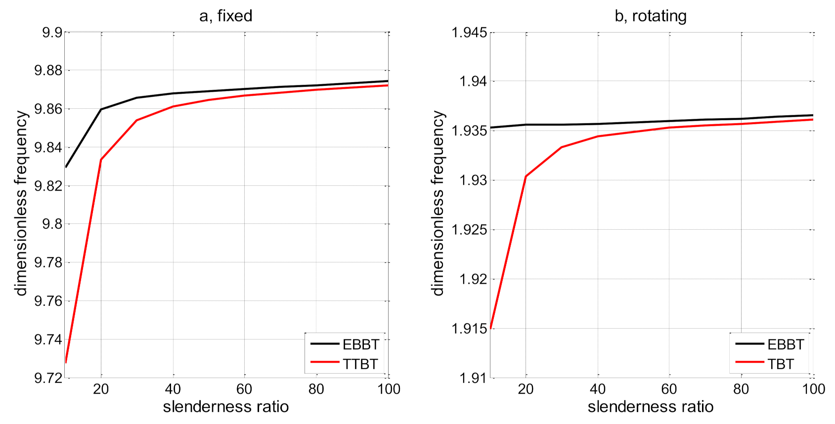
In Table 1, we have also provided the results for small values of slenderness ratio (very thick beams). In such cases, it is evident that as the beam is thicker, the resonant or natural frequency is getting smaller. Such finding is valid for both EBBT and TBT. Basically and expectedly, values of very thick beams are more accurate with TBT as the shearing effects are counted. Defining L/h = 5 as the very thick, L/h = 20 as thick and L/h = 100 as thin beams, it is observable that the first natural frequency for very thick beams is the smallest, for moderate thick beams, the frequency is medium and, for the thin beams, the frequency is the smallest. Such observations are authentic using either EBBT or TBT models.
Figure 2 demonstrates changes of the fundamental frequency with slenderness ratio for both Euler–Bernoulli and Timoshenko micro-beam models. Figure 2a shows results of the fixed beam. However, Figure 2b shows frequencies of the beam rotting around the fixed axis when second speed factor (lateral speed factor) is equal to . It is evident that by increasing the slenderness ratio, frequency is increasing. This variation is quite steep for TBT rather than EBBT. For TBT; when , most significant changes take place, when slenderness ratio is in the middle range (), mild variations do happen and for long beams () changes are negligible. For EBBT, smaller changes take place and this fact is more eye-catching when the beam is rotating.
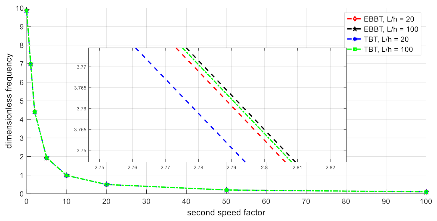
Figure 3 depicts variations of the fundamental frequency based on various values of second (lateral) speed factor (). For the desired accuracy of hundreds; regardless of the beam theory, and slenderness ratio, there is a similar behavior observed. Accordingly, either for Euler–Bernoulli or Timoshenko beam theories; and for both short and long beams, fundamental frequency is decreasing as the lateral speed factor increases. Most remarkable shifts happen when . Gentle changes are observed when . For big values of the second speed factor, dimensionless frequency is a small number and variations are insignificant. It is also good to note that for accuracy over hundreds, frequencies are greater in the order of corresponding theories as: short TBT, short EBBT, long TBT, and long EBBT.
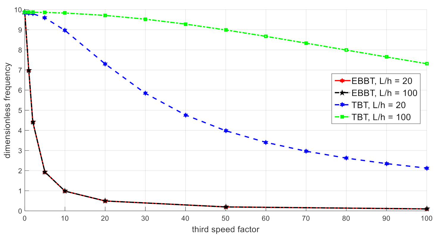
Figure 4 shows variations of fundamental frequency according to the third (angular) speed factor (). Similar to the variations of frequency with the second speed factor, dimensionless fundamental frequency also decreases as the third speed factor increases. However, there is a difference with the type of variations with angular speed factor. Type of theory selected is a matter of consideration here. This means, for EBBT regardless of the beam slenderness ratio results are the same for both short and long beams. In contrast; for TBT, if there is positive curvature with the increment of third speed factor, and if , negative curvature is observed with variable speed factors. As a result, variations of the micro-beam with angular speed factor totally depend on the beam theory used.
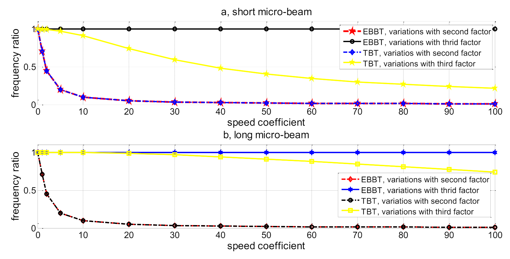
In Figure 5, profile of the frequency ratio () with lateral and angular speed factors is presented. Frequency ratio is the ratio of the frequencies derived from the rotating system to the corresponding frequencies of the fixed system. Based on the mentioned figure; for EBBT, there is no variation in the frequency ratio when system is rotating based on the angular displacement field. This means, when we neglect shear deformations, frequency of the system is affected only if rotational displacement is expressed in terms of lateral displacement. Both Figure 5a,b imply that, by increasing the lateral speed factor, both EBBT and TBT models show similar behavior and decrease. Another finding states that, for TBT model frequency ratio is decreasing as the angular speed factor increases and this decrement is gentle in comparison to the variations of frequency ratio with lateral speed factor. Finally, it is good to mention that based on the results I have obtained, third velocity factor does not have any impact upon the frequency of the micro-rotating beam.
6. Conclusions
In this research article, lateral vibration analysis of rotating micro-beams is studied with pinned–pinned boundary conditions and in the course of free vibrations. The micro-beam model is supposed to be located perpendicular to the rotating axis which is aligned with the lateral (transverse) direction. To capture the size dependencies of the beam model, the modified couple stress theory is adopted along with thin and thick beam theories (Euler–Bernoulli and Timoshenko). Rotational or angular displacement of the beam element is constrained to the translational displacement vectors based on a proportional relationship. Hamilton’s principle is utilized to derive the governing equations. For the case of ignoring shear effects which is a suitable model for thin beams (Euler–Bernoulli model), Galerkin’s approach is adopted for solution procedure. However, as for the case of thick beams and accounting shearing effects, system of coupled differential equations is obtained where the Galerkin’s approach does not work. In this regard, the Navier’s discretization method is adopted. Besides the shearing effects; the impact of slenderness ratio (ratio of the beam length to the beam thickness), impact of axial velocity factor, impact of lateral velocity factor, and impact of angular velocity factor are all discussed in detail. Results reveal that second speed factor (lateral velocity factor) does affects the system response in a similar and identical fashion for both thin and thick beams with any slenderness ratios. In other words, considering the second velocity factor (lateral), the beam thickness does not play a role in systems response. However, for the effects of third velocity parameter (angular or shearing strain factor), the Timoshenko beam with L/h = 100 shows the least mutations and variations, Timoshenko beam with L/h = 20 reveals moderate variations, and finally Euler–Bernoulli beam models, regardless of the slenderness ration, behave the most sensitively. In short, it can be inferred that with proper adoption of velocity parameters, one can readily manipulate the system’s response and natural frequency as required for any specific design. More importantly, thickness of the beam can also manipulate the response of rotating beams due to the presence of shearing strains. It is also good to note that the proposed model has the limitation of very thick beams meaning that for highly thick beams more in-depth theories should be adopted. Besides, gyration effects of rotation are also ignored in this study conveying for super-fast rotating systems, such effects should also be captured. Such findings can be highly applicable in MEMS energy harvesters, small-scaled piezoelectric vibration controllers, micro-resonator devices, microsensors, and small-sized gyroscopes and actuators.
Author Contributions
A.B. conceived this paper. A.B. and M.A. drafted the original manuscript. All authors have read and agreed to the published version of the manuscript.
Funding
This research received no external funding.
Institutional Review Board Statement
Not applicable.
Informed Consent Statement
Not applicable.
Data Availability Statement
Not applicable.
Conflicts of Interest
The authors declare no conflict of interest.
References
- Ghanbari, A.; Babaei, A. The new boundary condition effect on the free vibration analysis of micro-beams based on the modified couple stress theory. Int. Res. J. Appl. Basic Sci. 2015, 9, 274–279. [Google Scholar]
- Ghanbari, A.; Babaei, A.; Vakili-Tahami, F. Free vibration analysis of micro beams based on the modified couple stress theory, using approximate methods. Technology 2015, 3, 136–143. [Google Scholar]
- Iannacci, J. Microsystem based Energy Harvesting (EH-MEMS): Powering pervasivity of the Internet of Things (IoT)–A review with focus on mechanical vibrations. J. King Saud Univ. Sci. 2019, 31, 66–74. [Google Scholar] [CrossRef]
- Arabghahestani, M.; Poozesh, S.; Akafuah, N.K. Advances in Computational Fluid Mechanics in Cellular Flow Manipulation: A Review. Appl. Sci. 2019, 9, 4041. [Google Scholar] [CrossRef] [Green Version]
- Ren, Z.; Chang, Y.; Ma, Y.; Shih, K.; Dong, B.; Lee, C. Leveraging of MEMS Technologies for Optical Metamaterials Applications. Adv. Opt. Mater. 2020, 8, 1900653. [Google Scholar] [CrossRef]
- Kanno, I. Piezoelectric MEMS: Ferroelectric thin films for MEMS applications. Jpn. J. Appl. Phys. 2018, 57, 040101. [Google Scholar] [CrossRef] [Green Version]
- Arabghahestani, M.; Akafuah, N.K.; Saito, K. Computational fluid dynamics and scaling study on ultrasonic pulsation atomizer for waterborne paint. At. Sprays 2021, 31, 29–52. [Google Scholar] [CrossRef]
- Qu, J.; Wu, H.; Cheng, P.; Wang, Q.; Sun, Q. Recent advances in MEMS-based micro heat pipes. Int. J. Heat Mass Transf. 2017, 110, 294–313. [Google Scholar] [CrossRef]
- Łuczak, S.; Grepl, R.; Bodnicki, M. Selection of MEMS Accelerometers for Tilt Measurements. J. Sens. 2017, 2017, 9796146. [Google Scholar] [CrossRef]
- Lysenko, I.E.; Tkachenko, A.V.; Sherova, E.V.; Nikitin, A.V. Analytical Approach in the Development of RF MEMS Switches. Electronics 2018, 7, 415. [Google Scholar] [CrossRef] [Green Version]
- Arabghahestani, M.; Karimian, S. Molecular dynamics simulation of rotating carbon nanotube in uniform liquid argon flow. J. Mol. Liq. 2017, 225, 357–364. [Google Scholar] [CrossRef]
- Babaei, A. Forced vibrations of size-dependent rods subjected to: Impulse, step, and ramp excitations. Arch. Appl. Mech. 2021, 1–13. [Google Scholar] [CrossRef]
- Babaei, A.; Ghanbari, A.; Vakili-Tahami, F. Size-dependent behavior of functionally graded micro-beams, based on the modified couple stress theory. Technology 2015, 3, 364–372. [Google Scholar]
- Yang, F.; Chong, A.; Lam, D.; Tong, P. Couple stress based strain gradient theory for elasticity. Int. J. Solids Struct. 2002, 39, 2731–2743. [Google Scholar] [CrossRef]
- Ghadiri, M.; Shafiei, N. Vibration analysis of rotating functionally graded Timoshenko microbeam based on modified couple stress theory under different temperature distributions. Acta Astronaut. 2016, 121, 221–240. [Google Scholar] [CrossRef]
- Qian, Y.-J.; Yang, X.-D.; Zhang, W.; Liang, F.; Yang, T.-Z.; Ren, Y. Flutter Mechanism of Timoshenko Beams in Supersonic Flow. J. Aerosp. Eng. 2019, 32, 04019033. [Google Scholar] [CrossRef]
- Beni, Y.T.; Mehralian, F.; Razavi, H. Free vibration analysis of size-dependent shear deformable functionally graded cylindrical shell on the basis of modified couple stress theory. Compos. Struct. 2015, 120, 65–78. [Google Scholar] [CrossRef]
- Thai, S.; Thai, H.-T.; Vo, T.P.; Patel, V.I. A simple shear deformation theory for nonlocal beams. Compos. Struct. 2018, 183, 262–270. [Google Scholar] [CrossRef]
- Al-Basyouni, K.; Tounsi, A.; Mahmoud, S. Size dependent bending and vibration analysis of functionally graded micro beams based on modified couple stress theory and neutral surface position. Compos. Struct. 2015, 125, 621–630. [Google Scholar] [CrossRef]
- Akbaş, Ş.D. Free Vibration of Edge Cracked Functionally Graded Microscale Beams Based on the Modified Couple Stress Theory. Int. J. Struct. Stab. Dyn. 2017, 17, 1750033. [Google Scholar] [CrossRef]
- Yin, S.; Deng, Y.; Zhang, G.; Yu, T.; Gu, S. A new isogeometric Timoshenko beam model incorporating microstructures and surface energy effects. Math. Mech. Solids 2020, 25, 2005–2022. [Google Scholar] [CrossRef]
- Nateghi, A.; Salamat-Talab, M. Thermal effect on size dependent behavior of functionally graded microbeams based on modified couple stress theory. Compos. Struct. 2013, 96, 97–110. [Google Scholar] [CrossRef]
- Ke, L.-L.; Wang, Y.-S. Size effect on dynamic stability of functionally graded microbeams based on a modified couple stress theory. Compos. Struct. 2011, 93, 342–350. [Google Scholar] [CrossRef]
- Babaei, A.; Ahmadi, I. Dynamic vibration characteristics of non-homogenous beam-model MEMS. J. Multidiscip. Eng. Sci. Tech. 2017, 4, 6807–6814. [Google Scholar]
- Yilmaz, M.C.; Orhan, S. Determination of the stiffness properties of a complex RF MEMS by superposition and finite elements method. Microsyst. Technol. 2019, 25, 2561–2569. [Google Scholar] [CrossRef]
- Babaei, A.; Rahmani, A.; Ahmadi, I. Transverse vibration analysis of nonlocal beams with various slenderness ratios, undergoing thermal stress. Arch. Mech. Eng. 2019, 66, 5–24. [Google Scholar]
- Babaei, A.; Rahmani, A. On dynamic-vibration analysis of temperature-dependent Timoshenko microbeam possessing mutable nonclassical length scale parameter. Mech. Adv. Mater. Struct. 2018, 27, 1451–1458. [Google Scholar] [CrossRef]
- Sur, A.; Mondal, S.; Kanoria, M. Memory response in the vibration of a micro-scale beam due to time-dependent thermal loading. Mech. Based Des. Struct. Mach. 2020, 2020, 1745078. [Google Scholar] [CrossRef]
- Babaei, A.; Noorani, M.-R.S.; Ghanbari, A. Temperature-dependent free vibration analysis of functionally graded micro-beams based on the modified couple stress theory. Microsyst. Technol. 2017, 23, 4599–4610. [Google Scholar] [CrossRef]
- Ilkhani, M.; Hosseini-Hashemi, S. Size dependent vibro-buckling of rotating beam based on modified couple stress theory. Compos. Struct. 2016, 143, 75–83. [Google Scholar] [CrossRef]
- Shafiei, N.; Kazemi, M.; Ghadiri, M. On size-dependent vibration of rotary axially functionally graded microbeam. Int. J. Eng. Sci. 2016, 101, 29–44. [Google Scholar] [CrossRef]
- Babaei, A. Forced vibration analysis of non-local strain gradient rod subjected to harmonic excitations. Microsyst. Technol. 2021, 27, 821–831. [Google Scholar] [CrossRef]
- Rahmani, A.; Babaei, A.; Faroughi, S. Vibration characteristics of functionally graded micro-beam carrying an attached mass. Mech. Adv. Compos. Struct. 2020, 7, 49–58. [Google Scholar]
- Babaei, A. Longitudinal vibration responses of axially functionally graded optimized MEMS gyroscope using Rayleigh–Ritz method, determination of discernible patterns and chaotic regimes. SN Appl. Sci. 2019, 1, 831. [Google Scholar] [CrossRef] [Green Version]
- Babaei, A.; Rahmani, A. Vibration analysis of rotating thermally-stressed gyroscope, based on modified coupled displacement field method. Mech. Based Des. Struct. Mach. 2020, 1–10. [Google Scholar] [CrossRef]
- Sarparast, H.; Ebrahimi-Mamaghani, A.; Safarpour, M.; Ouakad, H.M.; Dimitri, R.; Tornabene, F. Nonlocal study of the vibration and stability response of small-scale axially moving supported beams on viscoelastic-Pasternak foundation in a hygro-thermal environment. Math. Methods Appl. Sci. 2020. [Google Scholar] [CrossRef]
- Ebrahimi-Mamaghani, A.; Forooghi, A.; Sarparast, H.; Alibeigloo, A.; Friswell, M. Vibration of viscoelastic axially graded beams with simultaneous axial and spinning motions under an axial load. Appl. Math. Model. 2021, 90, 131–150. [Google Scholar] [CrossRef]
- Ebrahimi, F.; Mokhtari, M. Transverse vibration analysis of rotating porous beam with functionally graded microstructure using the differential transform method. J. Braz. Soc. Mech. Sci. Eng. 2015, 37, 1435–1444. [Google Scholar] [CrossRef]
- Chen, Y.; Zhang, J.; Zhang, H. Free vibration analysis of rotating tapered Timoshenko beams via variational iteration method. J. Vib. Control 2017, 23, 220–234. [Google Scholar] [CrossRef]
- Babaei, A.; Yang, C.X. Vibration analysis of rotating rods based on the nonlocal elasticity theory and coupled displacement field. Microsyst. Technol. 2019, 25, 1077–1085. [Google Scholar] [CrossRef]
Figure 1.
Simply-supported micro-beam rotating around axis.

Figure 2.
Variations of fundamental frequency with slenderness ratio ((a) fixed micro-beam, (b) rotating micro-beam).
Figure 2.
Variations of fundamental frequency with slenderness ratio ((a) fixed micro-beam, (b) rotating micro-beam).

Figure 3.
Variations of dimensionless fundamental frequency with lateral velocity (speed) factor.

Figure 4.
Variations of dimensionless fundamental frequency with angular speed factor.

Figure 5.
Variations of frequency ratio with angular speed factors. ((a) , (b) ).


Table 1.
Comparison of dimensionless frequency for different values of slenderness ratio.
| Present (EBBT) | Difference (EBBT) % | Present (TBT) | Difference (TBT) % | [10] (NLET) | [15] (NLET) | |
|---|---|---|---|---|---|---|
| L/h = 5 | 9.7112 | - | 9.34297 | - | - | - |
| L/h = 10 | 9.8293 | - | 9.7275 | - | - | - |
| L/h = 15 | 9.8517 | - | 9.80555 | - | - | - |
| 9.8597 | 0.3–0.2 | 9.8335 | 0.04–0.47 | 9.8296 | 9.8797 | |
| 9.8693 | 0.06–0.03 | 9.8647 | 0.02–0.08 | 9.8631 | 9.8724 | |
| 9.8743 | 0.06–0.04 | 9.8720 | 0.04–0.02 | 9.8680 | 9.8700 |
Publisher’s Note: MDPI stays neutral with regard to jurisdictional claims in published maps and institutional affiliations. |
© 2021 by the authors. Licensee MDPI, Basel, Switzerland. This article is an open access article distributed under the terms and conditions of the Creative Commons Attribution (CC BY) license (https://creativecommons.org/licenses/by/4.0/).
Share and Cite
MDPI and ACS Style
Babaei, A.; Arabghahestani, M. Free Vibration Analysis of Rotating Beams Based on the Modified Couple Stress Theory and Coupled Displacement Field. Appl. Mech. 2021, 2, 226-238. https://0-doi-org.brum.beds.ac.uk/10.3390/applmech2020014
AMA Style
Babaei A, Arabghahestani M. Free Vibration Analysis of Rotating Beams Based on the Modified Couple Stress Theory and Coupled Displacement Field. Applied Mechanics. 2021; 2(2):226-238. https://0-doi-org.brum.beds.ac.uk/10.3390/applmech2020014
Chicago/Turabian StyleBabaei, Alireza, and Masoud Arabghahestani. 2021. "Free Vibration Analysis of Rotating Beams Based on the Modified Couple Stress Theory and Coupled Displacement Field" Applied Mechanics 2, no. 2: 226-238. https://0-doi-org.brum.beds.ac.uk/10.3390/applmech2020014