A Miniature pH Probe Using Functional Microfiber Bragg Grating †

Guangdong Provincial Key Laboratory of Optical Fiber Sensing and Communications, Institute of Photonics Technology, Jinan University, Guangzhou 510632, China
*
Author to whom correspondence should be addressed.
†
This is the extended version of “Biofuncationalized microfiber Bragg grating for acid-based sensing” in SPIE conference 2014.
Optics 2020, 1(2), 202-212; https://0-doi-org.brum.beds.ac.uk/10.3390/opt1020016
Submission received: 18 June 2020
/
Revised: 15 July 2020
/
Accepted: 16 July 2020
/
Published: 11 August 2020
(This article belongs to the Special Issue Recent Development of Resonance-Based Optical Sensors and Biosensors)
Abstract
:Operando and precisely probing aqueous pH is fundamentally demanded, both in chemical and biological areas. Conventional pH probes, subjected to the larger size, are probably unfit for application in some extreme scenarios, such as a trace amount of samples. In this paper, we have further developed the pH sensor that leverages the microfiber Bragg grating with an ultra-compact size down to an order of magnitude of 10−14 m3. Using the electrostatic self-assembly layer-by-layer technique, the functional film consisting of sodium alginate, which harnesses a pH-dependent hygroscopicity, is immobilized on the fiber surface. Consequently, the alteration of aqueous pH could be quantitatively indicated by the wavelength shift of the grating resonance via the refractive index variation of the sensing film due to the water absorption or expulsion. The grating reflections involving fundamental mode and higher order mode exhibit the sensitivities of −72 pm/pH and −265 pm/pH, respectively. In addition, temperature compensation can be facilitated by the recording of the two reflections simultaneously. Furthermore, the modeling and simulation results predict the pivotal parameters of the configuration in sensitivity enhancement. The proposed proof-of-concept enriches the toolbox of pH sensor for catering to the need of detection in some extremely small spaces—for example, the living cells or the bio-tissues.

1. Introduction
A myriad of applications, such as chemistry analyzation, environmental protection, the food industry, drug processing and medical diagnostics, necessitate the evaluation of several vital chemical indicators. Thereinto, the alteration of aqueous pH is capable of unraveling the chemical reaction and biological activity. Tremendous efforts, as a result, have been devoted to facilitating the real-time and in situ pH detection technique for meeting the requirements of the scenarios mentioned above. Accordingly, a pH probe possessing the superiorities of versatility, flexibility, and compactness is highly pursued.
The fiber-optic pH sensor becomes a competitive candidate that precedes in slenderness, maturity and low-cost of fabrication, variability, high sensitivity, biological compatibility, electromagnetic immunity and capability of remote manipulation [1,2,3]. Various sensing strategies involving leveraging optical fibers have been involved in enabling the pH measurement.
Fluorescence and Raman fiber probes were explored to monitor the pH in living cells [4,5] and human tissue [6]. The pH-dependent fluorophores or Raman tags were routinely applied as the transducers. Several efforts implemented the fiber pH sensor that utilizes the change in light transmittance as the indicator. The transmittance deteriorated due to the light diffusion or absorption, which could be influenced by the sample acidity [7,8]. For those demonstrations, optical fibers mainly functioned as the light carrier rather than the pH responder.
On the other hand, the fiber could transduce the aqueous pH value into the optical signal with the assistance of the functional materials. Miscellaneous transducing regimes of fiber optical sensors were spurred to get involved in in situ pH monitoring, including a pulsed laser beam [9], interferometer [10,11,12,13,14], resonator [15,16], and long-period gratings [17,18,19]. In the portfolio, fiber Bragg gratings (FBGs) occupied an eye-catching niche, lying in the intrinsic reflected signal, short working length and sharp signal bandwidth. Hartings et al. demonstrated an FBG pH probe through the utility of a chromophore coating in which the heating release would be altered by the pH. The probe could respond to the pH change over a range of 2.5–10 via the temperature variation of the coating [20]. Moreover, tilted FBG (TFBG) was also presented in the pH sensing area, studied by Lopez Aldaba et al. A polyaniline coating deposited on the surface allowed the tFBG to sense the pH alteration over the range of 2–12 with a sensitivity of 82 pm/pH [21]. Cheng et al. reported a pH-sensitive hydrogel-coated FBG that was written in the photosensitive polymer fiber. A pH sensitivity of −0.41 nm/pH and a fast response time of 30 s were obtained [22]. Most recently, Janting et al. also demonstrated a pH-sensitive hydrogel decorated PMMA-based polymer optical fiber Bragg grating. The work featured further miniaturization of the sensor through an etching fiber from 150 to 80 μm in diameter [23].
Microfiber, a kind of optical fiber with a diameter below 10 microns, not only improves the light–analyte interaction by virtue of the larger evanescent field but also scales down the cross-section of the fiber drastically [24,25,26,27,28,29]. The Bragg grating written in microfiber (μFBG) can orchestrate the advantages of both configurations and thus has become a fast-developing technique, from fundamental research to application investigation [30,31,32,33,34,35,36,37,38,39,40,41,42,43].
In this paper, we further develop the miniature pH probe using the microfiber Bragg grating. The functional layer of sodium alginate gel, which is pH-responsive, is immobilized on the microfiber surface through the electrostatic self-assembly technique [44]. In addition to the previous results, we utilize the two Bragg resonances, which are derived by the fundamental and higher order mode coupling, to conduct the acidity monitoring and the ambient temperature compensation. Furthermore, by the modeling analysis, the route for improving the pH sensitivity of the proposed proof-of-concept is elucidated.
2. Methods and Principle
2.1. Materials
The optical fibers were the telecom multimode (62.5/125) silica fibers, which was purchased from Corning Inc. (Corning, USA). Meanwhile, 98% sulfuric acid (H2SO4), 30% hydrogen peroxide (H2O2), hydrochloric acid (HCl), sodium hydroxide (NaOH), and sucrose were obtained from Sangon Biotech (Shanghai, China). Sodium alginate (SA) and ethylene imine polymer (PEI) were bought from Tianjin Yongda (Tianjin, China) and Aladdin (Shanghai, China), respectively. All the chemicals were of analytical grade. Deionized (DI) water was used throughout the experiment.
2.2. Fabrication of Microfiber Bragg Grating
The multimode fiber was tapered to the microfiber with a waist diameter of 4 μm through the flame-heated drawing technique [33,34,35,44]. We adopted the fast tapering method (<10 s) to minimize the effect of core expansion. Thus, the diameter of the core and cladding could be considered to decrease proportionally during the drawing process. In addition, the abrupt transition region of microfiber stemmed from the fast tapering process would excite more modes into the coupling, enabling more resonances that offer additional indicators for the measurement [33,34,35]. A homemade FBG inscription system comprising a 193 nm ultraviolet (UV) excimer laser (BraggStar Industrial, Coherent, Santa Clara, CA, USA) and a phase mask (Ibsen Photonics, Farum, Denmark) with a pitch of 1073.2 nm was employed to imprint the nanoscale-periodical index pattern into the microfiber, shown as Figure 1a. The repetition rate of the laser was set to 200 Hz. The UV energy density was adjusted to 120 mJ/cm2 per pulse through a cylindrical lens (Thorlabs, Newton, USA). The UV-laser exposing was spatially immobilized and focused on the waist of the microfiber. The grating length was determined by the width of the laser beam (3 mm). The time of exposure was 1 min. Figure 1b reveals the experimental setup of the μFBG sensing system. A broadband LED source (BBS, GoLight, Shenzhen, China) with a wavelength range of 1250–1650 nm and an average power density of −20 dBm/nm was launched into the μFBG via a circulator (Thorlabs, Newton, MA, USA) for the preparation of the background light reference. An optical spectrum analyzer (OSA, AQ6370B, Yogokawa, Tokyo, Japan), which was connected with the output port of the circulator, served as the spectral recorder with a resolution of 0.02 nm for monitoring the reflection of the μFBG sensor. According to the spectrum recorded in Figure 1c, two resonances are clearly observed, located at 1520 and 1488.45 nm, respectively. The deviation of the Bragg wavelengths of the μFBG with respect to the previous applied one [44] is probably as a result of the different strain preloaded on the microfiber in the inscription. With a larger fiber core of germanium-doping, more transverse modes can be supported in the multimode fiber. Dissimilar to the single-mode fiber-based μFBG that mainly couples propagating light between HE1m modes, the multimode fiber-based μFBG enables additional mode coupling feasibility. In this 4-μm-FBG, for instance, except for the main resonance, which is based on the coupling between the forward and backward HE11 mode (λ1 = 1520 nm), the dip at the shorter wavelength (λ2 = 1488.45 nm) denotes the intermodal coupling between HE11 and HE21. Despite a difference in strengths (−5 dB/−20 dB) between the two resonances, the wavelength encoding regime guarantees the accuracy of the measurement using μFBG in the following experiment.
2.3. RI-Response-Characterization of Microfiber Bragg Grating
μFBG can act as an intrinsic tip probe by cleaving or cutting it to a tip structure. Moreover, owing to the intrinsic reflection by the mFBG, the end face of the microfiber could be kept random to eliminate the laborious end-face treatment. Significantly, the total size of the working region of the sensor tip is only 4 × 10⁻⁵ mm3, enabling the capability of operation within tiny space, such as living cells and blood capillaries, which has a typical diameter of 9–10 μm. In this scenario, the resonances at longer and shorter wavelengths are expressed by R1 and R2, respectively. For characterizing the sensitivity of μFBG with respect to the surrounding refractive index (RI), the critical transducing parameter in the following experiment, a series of sucrose solutions with different RI ranging from 1.333 to 1.38 was prepared by changing the density of the sucrose in the DI water. By immersing another similar designed μFBG into the solution sequentially, the responses of R1 and R2 are plotted in Figure 2. R1 exhibited a sensitivity of 31.5 nm/RIU through a linear approximation. On the other hand, R2 presented a sensitivity of 127.4 nm/RIU, outperforming its counterpart by a 4-fold enhancement. The enhancement lies in the participation of the higher-order mode (HE21), which has a more substantial proportion of the evanescent field in the resonant performance. The larger the evanescent field proportion is, the higher benefit it can provide for sensing the outer RI change.
2.4. Functionalization of Microfiber Bragg Grating for pH Sensing
To achieve the detection of external pH, a functional layer of a μFBG is a necessary building block for transducing pH to RI. In this work, sodium alginate (SA) polymer is selected for playing the role of the transducer. SA often acts as a polyanion electrolyte in the milieu of neutral or alkalinity, taking advantage of containing carboxyl groups [45]. The electrostatic self-assembly layer-by-layer technique [46], therefore, was technically preferred to decorate the SA polymer functional film onto the fiber surface. The principle of the self-assembly process is shown in Figure 3a. By oxidizing the silica fiber, the negative charges were formed on the fiber surface. A polycation material of polyethylenimine (PEI) was added to construct an intermedium layer for the conglutination between silica fiber and SA through a strong electrostatic interaction. The process of functionalization was as follows, and was similar with the previous work [44].
- Prepare the piranha solution by mixing the 98% sulfuric acid and 30% hydrogen peroxide with a volume ratio of 4:1. Dissolve the SA and PEI with DI water to an identical density of 0.01 mol/L.
- Immerse the μFBG into the piranha solution for 1 h to endow the silica surface with abundant negative charges. Rinse the μFBG with DI water several times to eliminate the residual piranha solution.
- Move the μFBG into the PEI solution. After a standing of 15 min, the PEI layer would be anchored on the fiber through ironic adsorption and provides a positive charge. Rinse the positively charged μFBG with DI water several times to remove the residual PEI solution.
- Dip the μFBG into the SA solution, lasting for 15 min. The functional layer of SA could be immobilized and enable a negative charge. Rinse the functional μFBG with DI water several times to get rid of the unbind SA.
- Repeat Step 3 and Step 4 alternatively to obtain the required coating thickness. In this study, three double-layers were decorated on the μFBG surface.
- Dehumidify the functional device using an incubator that keeps a constant temperature of 70 °C and humidity of 30% for 12 h, and a pH-sensitive μFBG was ready for service.
Figure 3b illustrates the reflection spectra of the μFBG before and after functionalization. In contrast with the bare one, the treated μFBG drove R1 and R2 red shift and attenuates the overall intensity of reflection, indicating the encapsulation of a functional layer with a considerably high RI. The wavelength shifts of R1 and R2 were 1.28 and 4.72 nm, corresponding to the ratio of the RI sensitivity of the two resonances, respectively. In Figure 3b, the SEM images uncover the surface morphology of the μFBGs under different conditions. The upper images compare the bare (left) and functional (right) fibers. The distinction of surface roughness validated the existence of a layer that consists of irregularly shaped particles (SA) coated on the fiber. In addition, a mechanical crack of the functional layer, shown at the lower of the inset images, allowed us to investigate the clearer dissimilarity at the layer boundary.
The sensing principle is revealed in Figure 3c. The functional film contained two kinds of materials, although PEI particles had much less influence on the transducing due to the smaller size compared with SA (nm3 vs. μm3). SA, therefore, dominated the pH-RI decipherment through its COO- group. At lower pH milieu, SA dissociated COO- and formed carboxyl groups by combining with H+, reducing the hydrophilicity. As a result, the functional film maintained a high RI, allowing the μFBG to resonate at longer wavelengths. On the other hand, for a higher pH environment, COOH was ionized to (COO-), enabling the SA hydrogel to absorb water due to the enhancement of hydrophilicity [47,48]. As a result, RI of the functional layer decreased and thus could be manifested simply by the blue-shifts of the Bragg resonances, according to the RI sensing curve plotted in Figure 2.
3. Results and Discussion
3.1. pH Sensing Characterization
A series of pH indicating solutions was prepared, ranging from 4 to 12.5, through changing the ratio between the solvents and DI water. Here, the HCl and NaOH were the preferred solvents that can minimize the potential disturbance caused by the refractive index variation of the solutions. The refractive indices, tested by the refractometer, of the pH indicators were almost the same as the DI water (~1.333). Each testing period was set to 5 min.
By recording the reflection spectra in Figure 4a, the characteristics of the μFBG sensor towards pH are presented in Figure 4b,c, respectively. First, we scrutinized the response of R1 with regard to the alteration of pH value. The wavelength of R1 moved negatively from 1521.3 to 1520.71 nm as pH increased. By linear fitting with regression of over 99%, a pH sensitivity of −0.072 nm/pH could be deduced, as shown in Figure 4c. The negatively responsive curve as well as the enhancement of the intensity of the reflection confirmed the transducing mechanism; that is, the RI decrease of the SA film, as illustrated previously. The linear correlation is a synergic effect that combines the two linear mappings aforementioned, i.e., pH-RI of SA layer and RI-Bragg wavelength shift of μFBG. On the other hand, R2 contained a higher-order mode in the coupling, conveyed a pH sensitivity of −0.265 nm/pH, which was about four-fold higher compared to R1. This result was in accordance with the ratio between the R1 and R2 in the RI-responsive curve and further validated the transducing mechanism mediated by the SA layer. In addition, the result validates the repeatability of the sensing regime regarding the previous results [44].
3.2. Temperature Cross-Sensitivity Characterization
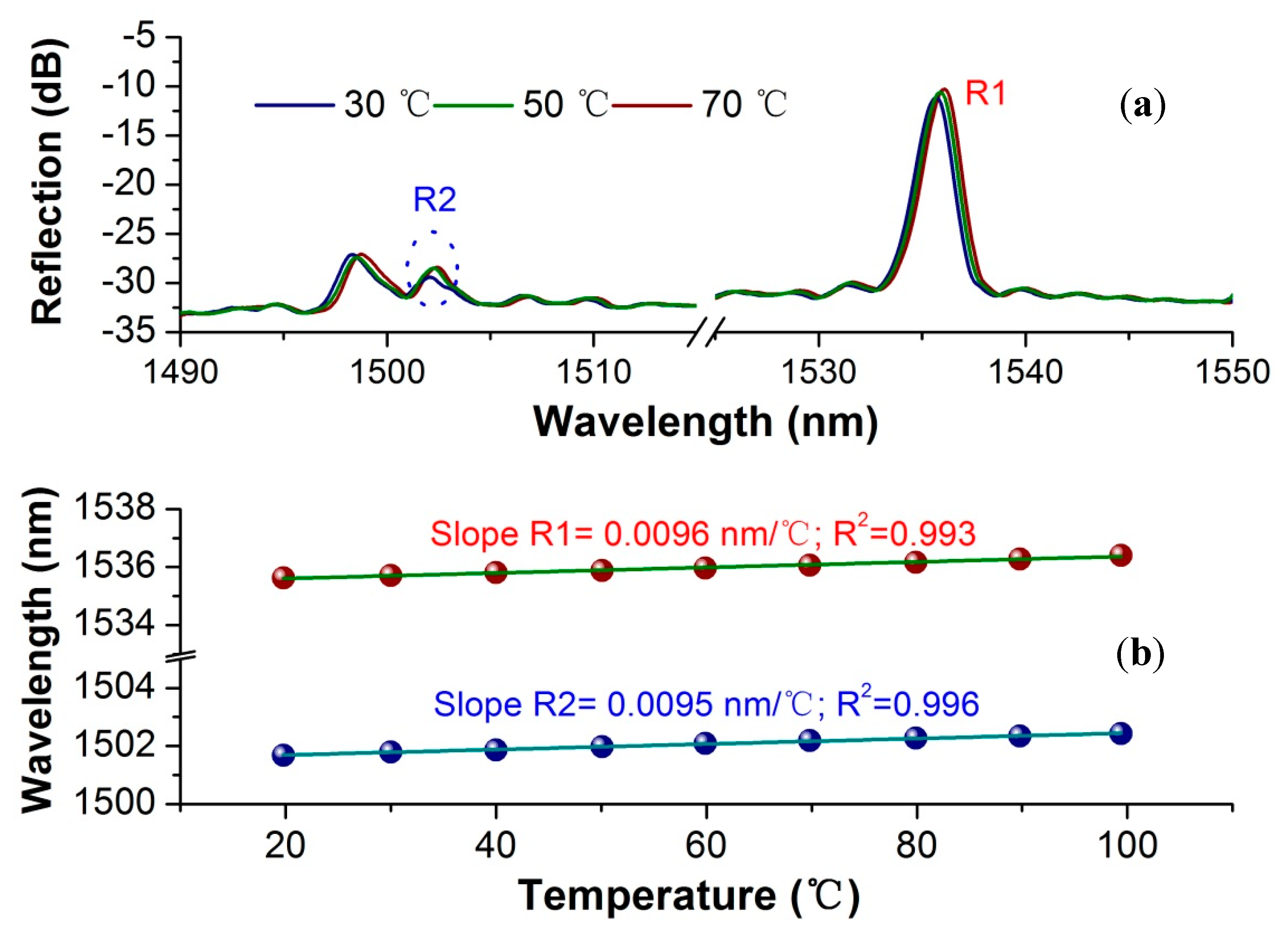
As we have seen, the temperature would affect the sensing results of optical fiber sensors upon applying the thermo-optic and thermo-expansion effects. The temperature cross-sensitivity, therefore, was an inevitable checkpoint of the proposed μFBG-based pH sensor. Another functional μFBG with similar design parameters was inserted into the tube oven, which could heat the intracavity from room temperature to 1800 °C. From the spectra shown in Figure 5a, we can see that both resonances moved to longer wavelengths with the same scale as the temperature was elevated. By portraying the data extracted from the typical points, a responsive curve could be deduced, as shown in Figure 5b. R1 and R2 exhibited similar sensitivities of 9.6 and 9.5 pm/°C, respectively, corroborating the previous results that acquired from different mode-coupling resonances [35]. Furthermore, it could be inferred that the SA layer acted a parallel thermo-optical influence on the resonances.
Therefore, with regard to the distinct gap between the pH sensitivities, the nuance between the temperature sensitivities of R1 and R2 allowed the functionalized μFBG to compensate for the temperature cross-sensitivity in pH sensing by orchestrating R1 and R2 simultaneously.
3.3. Model Analysis for Improving pH Sensitivity
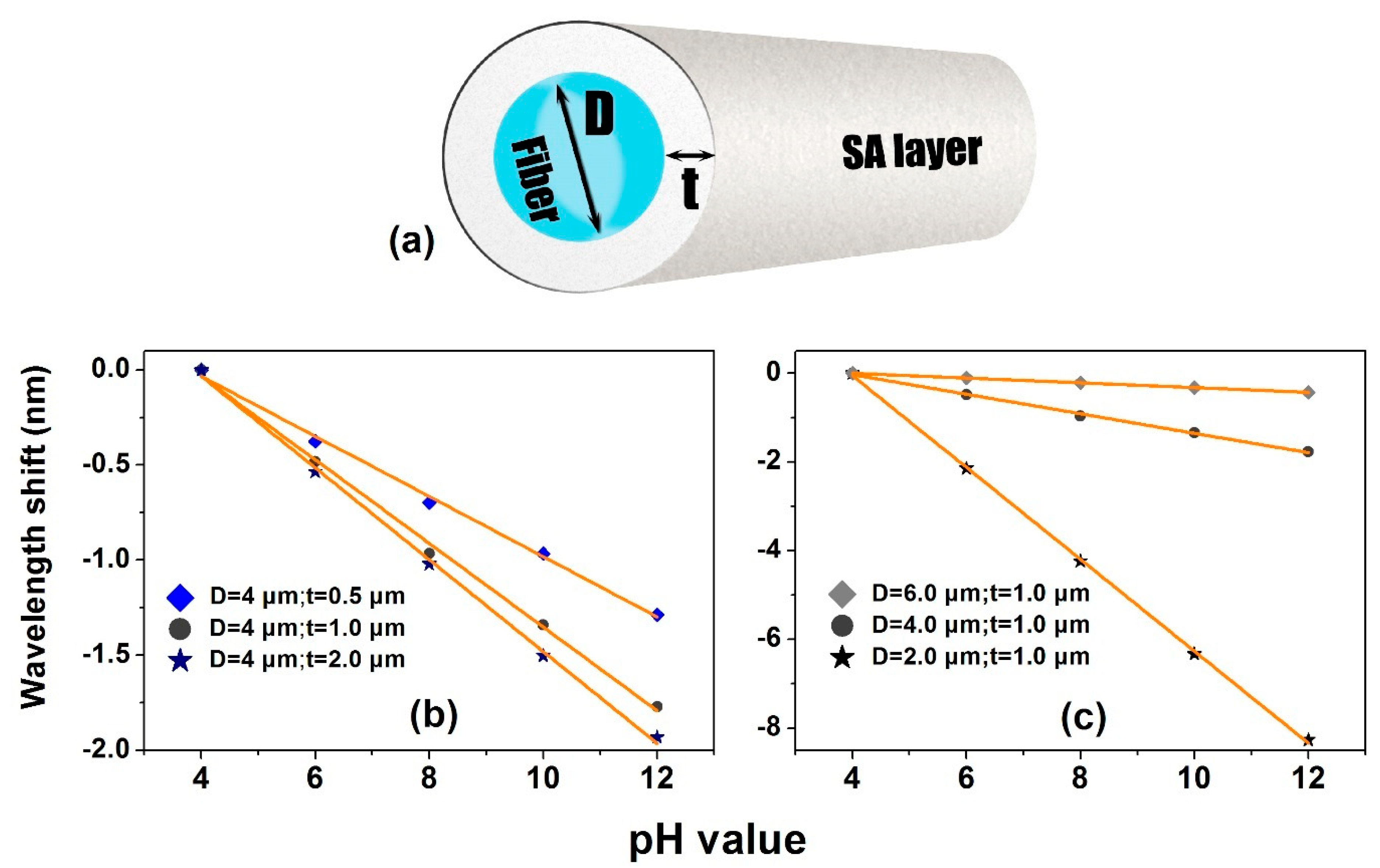
In order to fully understand the functionalities of the sensing structure and predict the avenue of sensitivity improvement, a four-layer cylindrical waveguide model was built for quantitative analysis of the modal variations and thus the resonant wavelengths. The layers, in turn, were the fiber core, cladding, functional coating and analytical solution environment from inner to outer, as drawn in Figure 6a.
At first, the refractive indices of the core and cladding were set as 1.47 and 1.444, respectively, corresponding to the data of the multimode fiber. The cladding diameter of the microfiber was represented by “D”. For the layer of SA film, the thickness of the film was signified as “t”. The refractive index of the film was assumed to ~1.38 when it was of dry state. The analytical liquid was prepared using the hydrochloric acid aqueous solution and sodium hydroxide aqueous solution to build the pH indicators, holding refractive indices that were similar to that of deionized water of 1.333. As the pH value increased, the SA layer was endowed with a greater water-absorbing capacity, allowing for reducing its refractive index. We assumed that the refractive index of the layer reduced from 1.38 to 1.36 linearly during the pH alteration from 4 to 12. Based on the assumption, we calculated the pH response of the μFBG (D = 4 μm; t = 1 μm) by the finite element method. The effective indices of the μFBG had altered due to RI decrease of the SA layer, resulting in the wavelength shifts of the Bragg reflections. R1 and R2 exhibited the sensitivities of −0.08 and −0.222 nm/pH, respectively, confirming the experimental results illustrated in Figure 4. As a consequence, the parameters applied in the previous case could be utilized as the benchmark for exploiting the way of sensitization.
Then, we firstly studied the correlation between the probe sensitivity and the thickness of the functional layer. In the simulation, “t” was tuned, ranging from 0.5 to 2 μm, while “D” was kept constant at 4 μm. Owing to the higher sensitivity, R2 was mainly taken into consideration, as shown in Figure 6b. It could be observed that a thicker functional layer enabled higher pH sensitivity. For example, the SA layer with 2 μm thickness decorated μFBG possessed a theoretical pH sensitivity of −0.24 nm/pH, which was one third higher than the 0.5 μm-layer. On the other hand, the diameter of μFBG was also a factor that affected the sensitivity. As “t” was fixed as 1 μm, the performances of the sensors with different diameters from 2 to 6 μm were investigated orderly. In Figure 6c, the results depicted that the smaller the diameter of the μFBG, the higher that sensitivity that could be obtained. A 2 μm diameter of the fiber endowed the sensor with a sensitivity of 1.04 nm/pH, twenty times higher than 6 μm-FBG. According to the analysis, when D = 2 μm and t = 2μm, the pH sensitivity of μFBG probe could be predicted to exceed 1.5 nm/pH.
4. Conclusions
In summary, as a promising photonic device that has conducted in bio/chemical sensing, microfiber Bragg grating is exploited as an intrinsic reflected fiber probe in the determination of aqueous pH. The sodium alginate gel, which is sensitive to the aqueous acidity and alkalinity, has been coated as sensing film onto the surface of microfiber grating by the electrostatic self-assembly layer-by-layer technique. The sensitivities are −72 and −265 pm/pH, corresponding to the fundamental mode and higher order mode participated reflections, respectively. Using theoretical modeling and simulation, the dependence of sensitivity to the film thickness and microfiber diameter is investigated. The enhancement of sensitivity in μFBG pH sensor can be obtained by means of reducing the microfiber diameter, thickening the functional layer and tracing the higher-order resonant peak. A few concerns should be noted as well. At first, the RI of pH-indicating solutions were kept the same in the experiment; however, the influence of the RI of the analytes to the sensor should be understood in the following study. Second, several functional coating techniques could be involved in this category for providing benefits, such as electropolymerization coating, metal coating [49] and optical functionalization [50]. Third, the thinner fiber, which is anticipated to have higher pH sensitivity, may result in higher insertion loss. Further investigation on a trade-off diameter should be carried out. Nevertheless, the μFBG-based pH probe promises excellent potential in bio/chemical areas because of its ultra-compact size, high sensitivity, ease of fabrication and facility.
Author Contributions
Y.R. and B.-O.G. proposed the idea; Y.R., P.X., and D.H. investigated the state-of-the-art of the topic and designed the experiment; Y.R., P.X., Y.Z., D.H., and Z.X. collaborated in accomplishing the experiment and simulation; L.L. provided the necessary suggestions in the experimental design and manuscript preparation; Y.R. prepared the original draft; Y.R. and B.-O.G. wrote, reviewed and edited the manuscript; Y.R., L.L., and B.-O.G. provided the project administration. All authors have read and agreed to the published version of the manuscript.
Funding
This research was funded by the National Natural Science Foundation of China (61775082, U1701268, 61805106), the Local Innovative and Research Teams Project of Guangdong Pearl River Talents Program (2019BT02X105), Guangdong Natural Science Foundation (2018A030313677), and the Fundamental Research Funds for the Central Universities.
Conflicts of Interest
The authors declare no conflict of interest.
References
- Chiavaioli, F.; Gouveia, A.J.C.; Jorge, A.S.P.; Baldini, F. Towards a Uniform Metrological Assessment of Grating-Based Optical Fiber Sensors: From Refractometers to Biosensors. Biosensors 2017, 7, 23. [Google Scholar] [CrossRef] [Green Version]
- Socorro-Leránoz, A.B.; Santano, D.; Del Villar, I.; Matias, I.R. Trends in the design of wavelength-based optical fibre biosensors (2008–2018). Biosens. Bioelectron. X 2019, 1, 100015. [Google Scholar] [CrossRef]
- Wang, X.-D.; Wolfbeis, O.S. Fiber-Optic Chemical Sensors and Biosensors (2015–2019). Anal. Chem. 2020, 92, 397–430. [Google Scholar] [CrossRef] [PubMed]
- Scaffidi, J.P.; Gregas, M.K.; Seewaldt, V.; Vo-Dinh, T. SERS-based plasmonic nanobiosensing in single living cells. Anal. Bioanal. Chem. 2009, 393, 1135–1141. [Google Scholar] [CrossRef] [Green Version]
- Wang, J.; Geng, Y.; Shen, Y.; Shi, W.; Xu, W.; Xu, S. SERS-active fiber tip for intracellular and extracellular pH sensing in living single cells. Sens. Actuators B Chem. 2019, 290, 527–534. [Google Scholar] [CrossRef]
- Wencel, D.; Kaworek, A.; Abel, T.; Efremov, V.; Bradford, A.; Carthy, D.; Coady, G.; McMorrow, R.C.N.; McDonagh, C. Optical Sensor for Real-Time pH Monitoring in Human Tissue. Small 2018, 14, 1803627. [Google Scholar] [CrossRef] [PubMed]
- Elsherif, M.; Moreddu, R.; Hassan, M.U.; Yetisen, A.K.; Butt, H. Real-time optical fiber sensors based on light diffusing microlens arrays. Lab Chip 2019, 19, 2060–2070. [Google Scholar] [CrossRef] [PubMed]
- Wang, K.-H.; Hsieh, J.-C.; Chen, C.-C.; Zan, H.-W.; Meng, H.-F.; Kuo, S.-Y.; Nguyễn, M.T.N. A low-cost, portable and easy-operated salivary urea sensor for point-of-care application. Biosens. Bioelectron. 2019, 132, 352–359. [Google Scholar] [CrossRef]
- Khan, R.M.; Kang, S.-W. Highly Sensitive and Wide-Dynamic-Range Multichannel Optical-Fiber pH Sensor Based on PWM Technique. Sensors 2016, 16. [Google Scholar] [CrossRef] [Green Version]
- Gu, B.; Yin, M.-J.; Zhang, A.P.; Qian, J.-W.; He, S. Low-cost high-performance fiber-optic pH sensor based on thin-core fiber modal interferometer. Opt. Express 2009, 17, 22296–22302. [Google Scholar] [CrossRef]
- Gu, B.; Yin, M.; Zhang, A.P.; Qian, J.; He, S. Biocompatible Fiber-Optic pH Sensor Based on Optical Fiber Modal Interferometer Self-Assembled With Sodium Alginate/Polyethylenimine Coating. IEEE Sens. J. 2012, 12, 1477–1482. [Google Scholar] [CrossRef]
- Zhao, Q.; Yin, M.; Zhang, A.P.; Prescher, S.; Antonietti, M.; Yuan, J. Hierarchically Structured Nanoporous Poly(Ionic Liquid) Membranes: Facile Preparation and Application in Fiber-Optic pH Sensing. J. Am. Chem. Soc. 2013, 135, 5549–5552. [Google Scholar] [CrossRef] [PubMed]
- Li, J.; Albri, F.; Maier, R.R.J.; Shu, W.; Sun, J.; Hand, D.P.; MacPherson, W.N. A Micro-Machined Optical Fiber Cantilever as a Miniaturized pH Sensor. IEEE Sens. J. 2015, 15, 7221–7228. [Google Scholar] [CrossRef]
- Pathak, A.K.; Chaudhary, D.K.; Singh, V.K. Broad range and highly sensitive optical pH sensor based on Hierarchical ZnO microflowers over tapered silica fiber. Sens. Actuators A Phys. 2018, 280, 399–405. [Google Scholar] [CrossRef]
- Zamarreño, C.R.; Hernáez, M.; Del Villar, I.; Matías, I.R.; Arregui, F.J. Optical fiber pH sensor based on lossy-mode resonances by means of thin polymeric coatings. Sens. Actuators B Chem. 2011, 155, 290–297. [Google Scholar] [CrossRef]
- Rivero, P.J.; Goicoechea, J.; Hernaez, M.; Socorro, A.B.; Matias, I.R.; Arregui, F.J. Optical fiber resonance-based pH sensors using gold nanoparticles into polymeric layer-by-layer coatings. Microsyst. Technol. 2016, 22, 1821–1829. [Google Scholar] [CrossRef]
- Yin, M.-J.; Yao, M.; Gao, S.; Zhang, A.P.; Tam, H.-Y.; Wai, P.-K.A. Rapid 3D Patterning of Poly(acrylic acid) Ionic Hydrogel for Miniature pH Sensors. Adv. Mater. 2016, 28, 1394–1399. [Google Scholar] [CrossRef]
- Mishra, S.K.; Zou, B.; Chiang, K.S. Wide-Range pH Sensor Based on a Smart- Hydrogel-Coated Long-Period Fiber Grating. IEEE J. Quantum Elect. 2017, 23, 284–288. [Google Scholar] [CrossRef]
- Ni, Y.-Q.; Ding, S.; Han, B.; Wang, H. Layer-by-layer assembly of polyelectrolytes-wrapped multi-walled carbon nanotubes on long period fiber grating sensors. Sens. Actuators B Chem. 2019, 301, 127120. [Google Scholar] [CrossRef]
- Hartings, M.R.; Castro, N.J.; Gill, K.; Ahmed, Z. A photonic pH sensor based on photothermal spectroscopy. Sens. Actuators B Chem. 2019, 301, 127076. [Google Scholar] [CrossRef]
- Lopez Aldaba, A.; González-Vila, Á.; Debliquy, M.; Lopez-Amo, M.; Caucheteur, C.; Lahem, D. Polyaniline-coated tilted fiber Bragg gratings for pH sensing. Sens. Actuators B Chem. 2018, 254, 1087–1093. [Google Scholar] [CrossRef]
- Cheng, X.; Bonefacino, J.; Guan, B.O.; Tam, H.Y. All-polymer fiber-optic pH sensor. Opt. Express 2018, 26, 14610–14616. [Google Scholar] [CrossRef] [PubMed] [Green Version]
- Janting, J.; Pedersen, J.K.M.; Woyessa, G.; Nielsen, K.; Bang, O. Small and Robust All-Polymer Fiber Bragg Grating Based pH Sensor. J. Lightwave Technol. 2019, 37, 4480–4486. [Google Scholar] [CrossRef] [Green Version]
- Tong, L.; Gattass, R.R.; Ashcom, J.B.; He, S.; Lou, J.; Shen, M.; Maxwell, I.; Mazur, E. Subwavelength-diameter silica wires for low-loss optical wave guiding. Nature 2003, 426, 816. [Google Scholar] [CrossRef] [PubMed]
- Brambilla, G. Optical fibre nanowires and microwires: A review. J. Opt. 2010, 12, 043001. [Google Scholar] [CrossRef]
- Ismaeel, R.; Lee, T.; Ding, M.; Belal, M.; Brambilla, G. Optical microfiber passive components. Laser Photonics Rev. 2013, 7, 350–384. [Google Scholar] [CrossRef] [Green Version]
- Lou, J.; Wang, Y.; Tong, L. Microfiber Optical Sensors: A Review. Sensors 2014, 14. [Google Scholar] [CrossRef] [Green Version]
- Chen, J.; Li, D.; Xu, F. Optical Microfiber Sensors: Sensing Mechanisms, and Recent Advances. J. Lightwave Technol. 2019, 37, 2577–2589. [Google Scholar] [CrossRef]
- Zhang, L.; Tang, Y.; Tong, L. Micro-/Nanofiber Optics: Merging Photonics and Material Science on Nanoscale for Advanced Sensing Technology. iScience 2020, 23, 100810. [Google Scholar] [CrossRef] [Green Version]
- Kou, J.-L.; Ding, M.; Feng, J.; Lu, Y.-Q.; Xu, F.; Brambilla, G. Microfiber-Based Bragg Gratings for Sensing Applications: A Review. Sensors 2012, 12. [Google Scholar] [CrossRef]
- Guan, B.-O.; Li, J.; Jin, L.; Ran, Y. Fiber Bragg gratings in optical microfibers. Opt. Fiber Technol. 2013, 19, 793–801. [Google Scholar] [CrossRef]
- Fang, X.; Liao, C.R.; Wang, D.N. Femtosecond laser fabricated fiber Bragg grating in microfiber for refractive index sensing. Opt. Lett. 2010, 35, 1007–1009. [Google Scholar] [CrossRef] [PubMed] [Green Version]
- Ran, Y.; Tan, Y.-N.; Sun, L.-P.; Gao, S.; Li, J.; Jin, L.; Guan, B.-O. 193nm excimer laser inscribed Bragg gratings in microfibers for refractive index sensing. Opt. Express 2011, 19, 18577–18583. [Google Scholar] [CrossRef]
- Ran, Y.; Jin, L.; Tan, Y.N.; Sun, L.P.; Li, J.; Guan, B.O. High-efficiency ultraviolet inscription of Bragg gratings in microfibers. IEEE Photon. J. 2012, 4, 181–186. [Google Scholar] [CrossRef]
- Ran, Y.; Jin, L.; Sun, L.P.; Li, J.; Guan, B.O. Temperature-Compensated Refractive-Index Sensing Using a Single Bragg Grating in an Abrupt Fiber Taper. IEEE Photon. J. 2013, 5, 7100208. [Google Scholar] [CrossRef]
- Ran, Y.; Jin, L.; Sun, L.-P.; Li, J.; Guan, B.-O. Bragg gratings in rectangular microfiber for temperature independent refractive index sensing. Opt. Lett. 2012, 37, 2649–2651. [Google Scholar] [CrossRef]
- Sun, D.; Guo, T.; Ran, Y.; Huang, Y.; Guan, B.-O. In-situ DNA hybridization detection with a reflective microfiber grating biosensor. Biosens. Bioelectron. 2014, 61, 541–546. [Google Scholar] [CrossRef] [Green Version]
- Ran, Y.; Jin, L.; Gao, S.; Sun, L.-P.; Huang, Y.-Y.; Li, J.; Guan, B.-O. Type IIa Bragg gratings formed in microfibers. Opt. Lett. 2015, 40, 3802–3805. [Google Scholar] [CrossRef]
- Yu, Z.; Jin, L.; Chen, L.; Li, J.; Ran, Y.; Guan, B. Microfiber Bragg Grating Hydrogen Sensors. IEEE Photon. Technol. Lett. 2015, 27, 2575–2578. [Google Scholar] [CrossRef]
- Xiao, P.; Liu, T.; Feng, F.-R.; Sun, L.-P.; Liang, H.; Ran, Y.; Jin, L.; Guan, B.-O. Spectral tuning of the diameter-dependent-chirped Bragg gratings written in microfibers. Opt. Express 2016, 24, 29749–29759. [Google Scholar] [CrossRef]
- Liu, T.; Liang, L.-L.; Xiao, P.; Sun, L.-P.; Huang, Y.-Y.; Ran, Y.; Jin, L.; Guan, B.-O. A label-free cardiac biomarker immunosensor based on phase-shifted microfiber Bragg grating. Biosens. Bioelectron. 2018, 100, 155–160. [Google Scholar] [CrossRef] [PubMed]
- Ran, Y.; Long, J.; Xu, Z.; Hu, D.; Guan, B.-O. Temperature monitorable refractometer of microfiber Bragg grating using a duet of harmonic resonances. Opt. Lett. 2019, 44, 3186–3189. [Google Scholar] [CrossRef] [PubMed]
- Liao, C.; Yang, K.; Wang, J.; Bai, Z.; Gan, Z.; Wang, Y. Helical Microfiber Bragg Grating Printed by Femtosecond Laser for Refractive Index Sensing. IEEE Photon. Technol. Lett. 2019, 31, 971–974. [Google Scholar] [CrossRef]
- Ran, Y.; Huang, Y.; Shen, X.; Sun, D.; Wang, X.; Jin, L.; Li, J.; Guan, B. Biofuncationalized microfiber Bragg grating for acid-based sensing. SPIE 2014, 9157, 915742. [Google Scholar]
- Blandino, A.; Macías, M.; Cantero, D. Glucose oxidase release from calcium alginate gel capsules. Enzyme Microb. Tech. 2000, 27, 319–324. [Google Scholar] [CrossRef]
- Decher, G. Fuzzy Nanoassemblies: Toward Layered Polymeric Multicomposites. Science 1997, 277, 1232. [Google Scholar] [CrossRef]
- Ju, H.K.; Kim, S.Y.; Lee, Y.M. pH/temperature-responsive behaviors of semi-IPN and comb-type graft hydrogels composed of alginate and poly(N-isopropylacrylamide). Polymer 2001, 42, 6851–6857. [Google Scholar] [CrossRef]
- Yuan, W.; Dong, H.; Li, C.M.; Cui, X.; Yu, L.; Lu, Z.; Zhou, Q. pH-Controlled Construction of Chitosan/Alginate Multilayer Film: Characterization and Application for Antibody Immobilization. Langmuir 2007, 23, 13046–13052. [Google Scholar] [CrossRef]
- González-Vila, Á.; Debliquy, M.; Lahem, D.; Zhang, C.; Mégret, P.; Caucheteur, C. Molecularly imprinted electropolymerization on a metal-coated optical fiber for gas sensing applications. Sens. Actuators B Chem. 2017, 244, 1145–1151. [Google Scholar] [CrossRef]
- Zhang, X.; Zou, X.; Luo, B.; Pan, W.; Yan, L.; Peng, W. Optically functionalized microfiber Bragg grating for RH sensing. Opt. Lett. 2019, 44, 4646–4649. [Google Scholar] [CrossRef]
Figure 1.
(a) The schematic of the Bragg grating written in microfiber (μFBG) fabrication that adopts 193 nm excimer laser inscription method. (b) The μFBG monitoring setup. BBS: the broadband source; OSA: the optical spectral analyzer. (c) Transmission and reflection spectra of the μFBG. HE11-HEx1: the mode coupling.

Figure 2.
RI-response curves of R1 and R2 of a μFBG.

Figure 3.
(a) Schematic of μFBG functionalization using the electrostatic self-assembly technique. (b) Spectral contrast between the bare and functional μFBGs. Inset: the scanning electron microscopic (SEM) images of the morphology of the μFBGs. Scale bar indicates a length of 10 μm. (c) Principle of pH-sensitive SA gel acting on the microfiber.

Figure 4.
(a) The spectra evolution of the μFBG along with the increment of the pH. The pH response curves of (b) R2 and (c) R1.
Figure 4.
(a) The spectra evolution of the μFBG along with the increment of the pH. The pH response curves of (b) R2 and (c) R1.

Figure 5.
(a) Spectral change during increasing of the temperature. (b) Temperature response curves of R2 and R1.
Figure 5.
(a) Spectral change during increasing of the temperature. (b) Temperature response curves of R2 and R1.

Figure 6.
Modeling and simulation of the μFBG pH sensor. (a) Modeling structure of the sensor; comparison of pH response curves of R2 of μFBGs with different (b) film thickness “t”; (c) fiber diameter “D”.
Figure 6.
Modeling and simulation of the μFBG pH sensor. (a) Modeling structure of the sensor; comparison of pH response curves of R2 of μFBGs with different (b) film thickness “t”; (c) fiber diameter “D”.

© 2020 by the authors. Licensee MDPI, Basel, Switzerland. This article is an open access article distributed under the terms and conditions of the Creative Commons Attribution (CC BY) license (http://creativecommons.org/licenses/by/4.0/).
Share and Cite
MDPI and ACS Style
Ran, Y.; Xiao, P.; Zhang, Y.; Hu, D.; Xu, Z.; Liang, L.; Guan, B.-O. A Miniature pH Probe Using Functional Microfiber Bragg Grating. Optics 2020, 1, 202-212. https://0-doi-org.brum.beds.ac.uk/10.3390/opt1020016
AMA Style
Ran Y, Xiao P, Zhang Y, Hu D, Xu Z, Liang L, Guan B-O. A Miniature pH Probe Using Functional Microfiber Bragg Grating. Optics. 2020; 1(2):202-212. https://0-doi-org.brum.beds.ac.uk/10.3390/opt1020016
Chicago/Turabian StyleRan, Yang, Peng Xiao, Yongkang Zhang, Deming Hu, Zhiyuan Xu, Lili Liang, and Bai-Ou Guan. 2020. "A Miniature pH Probe Using Functional Microfiber Bragg Grating" Optics 1, no. 2: 202-212. https://0-doi-org.brum.beds.ac.uk/10.3390/opt1020016