Electrodeposition of Ni-Co Alloys and Their Mechanical Properties by Micro-Vickers Hardness Test

 ,
, 
 ,
, 
Abstract
:1. Introduction
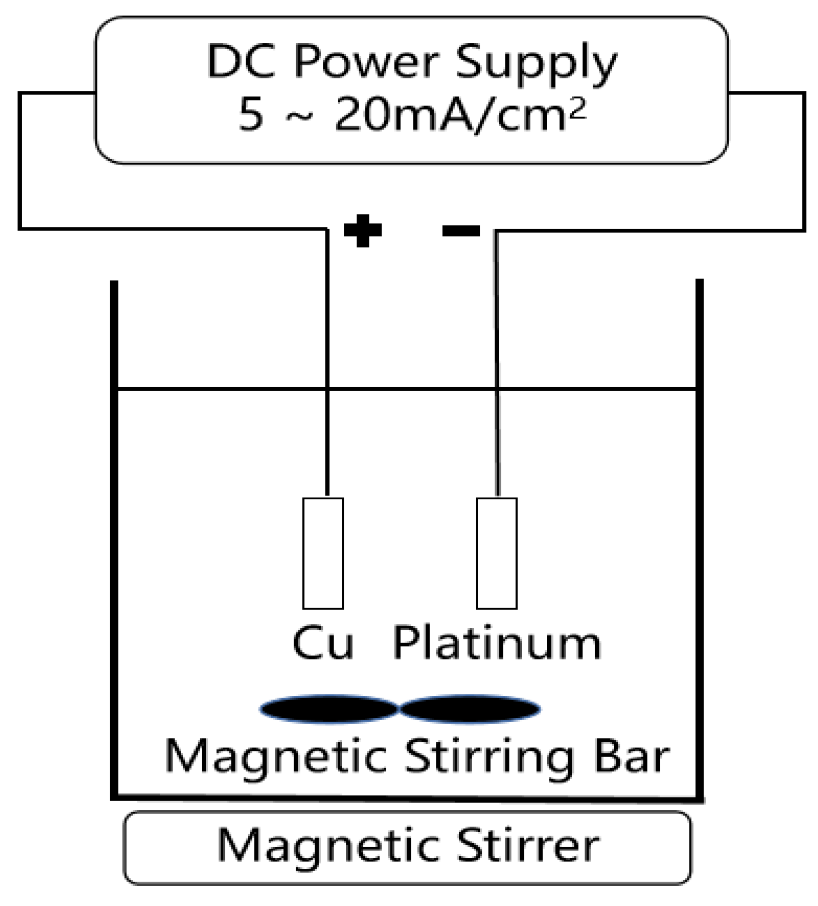
2. Experiment Methods
2.1. Electrodeposition of Ni-Co Alloy Deposits
2.2. Characterization of Ni-Co Alloy Deposits
3. Results and Discussion
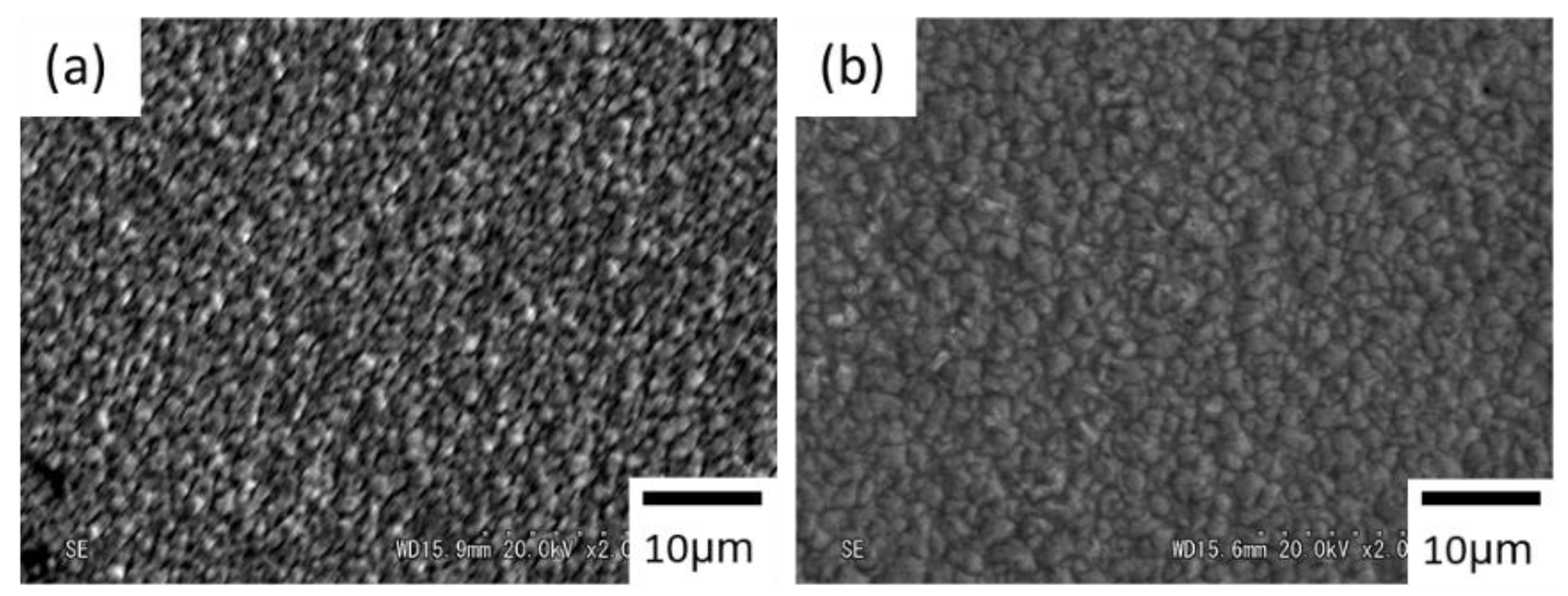
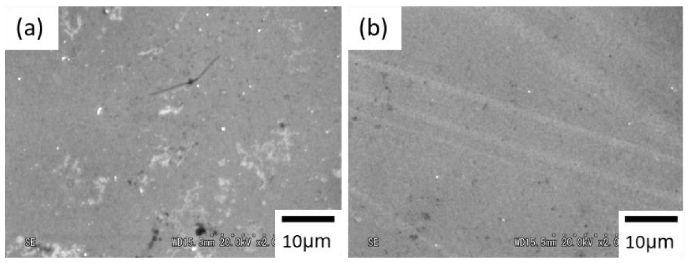
3.1. Morphology
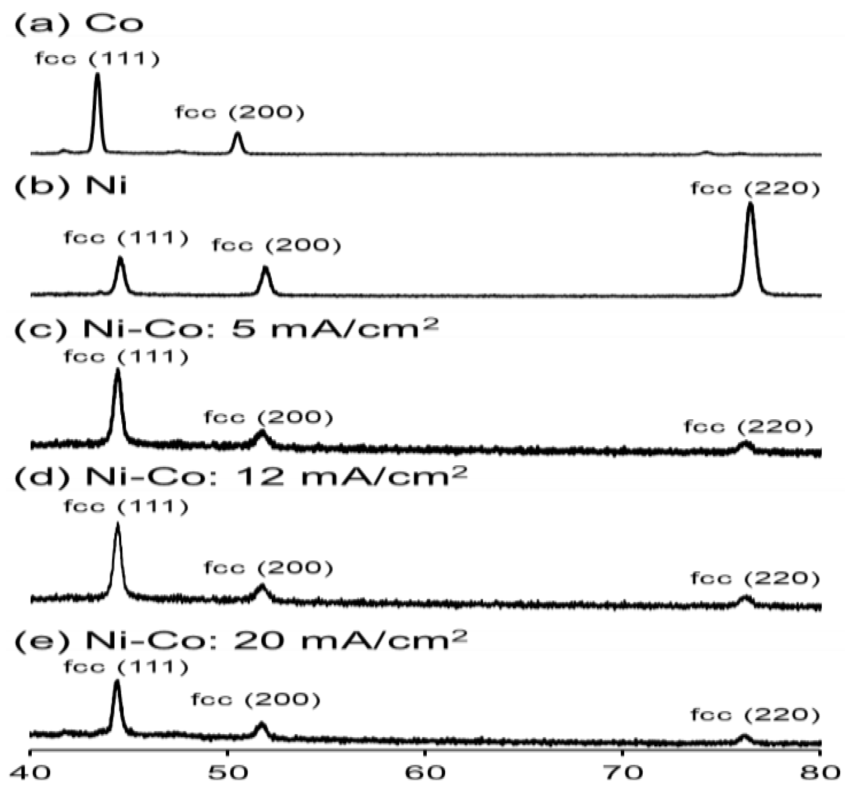
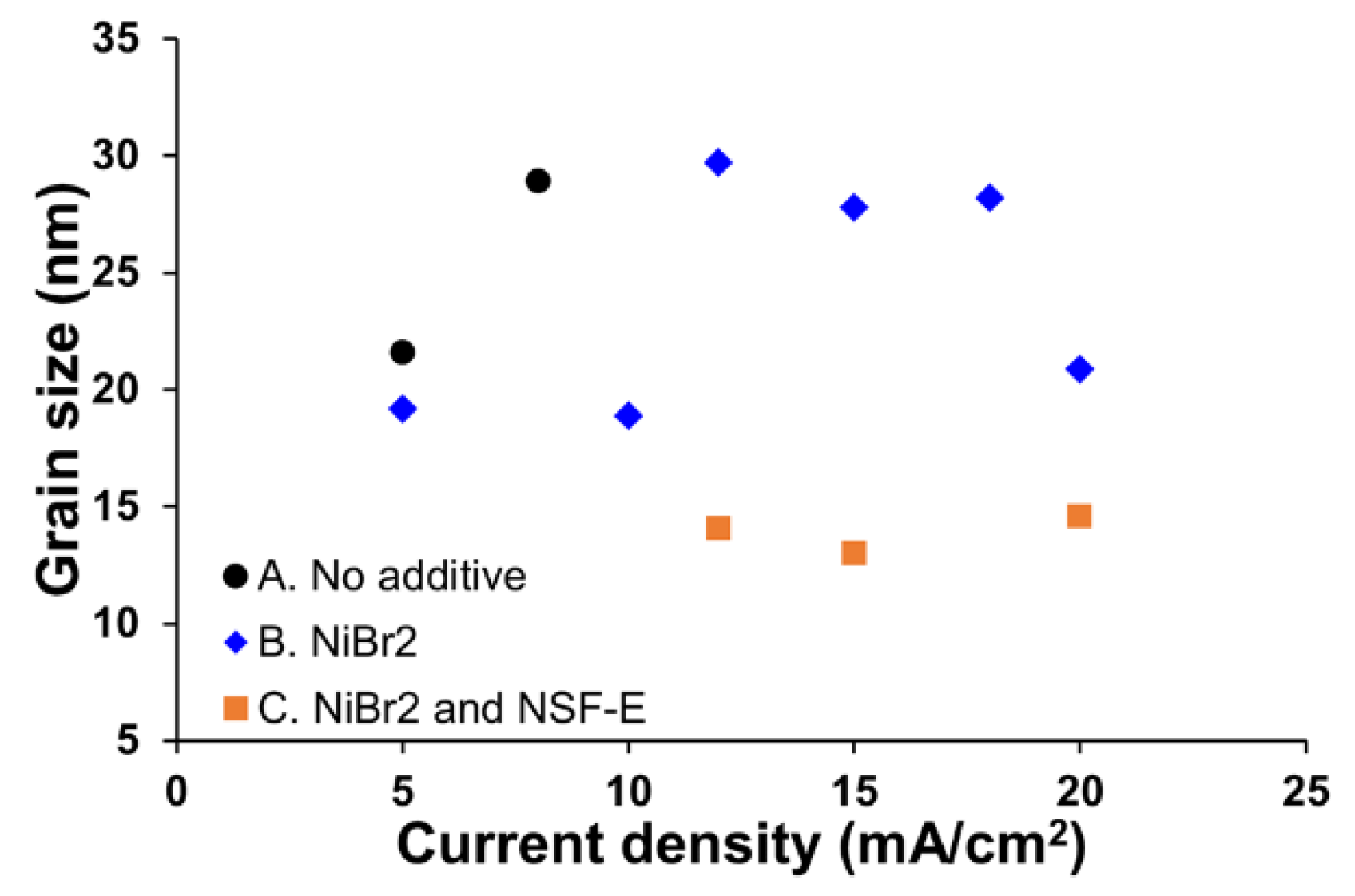
3.2. Crystal Structure and Grain Size
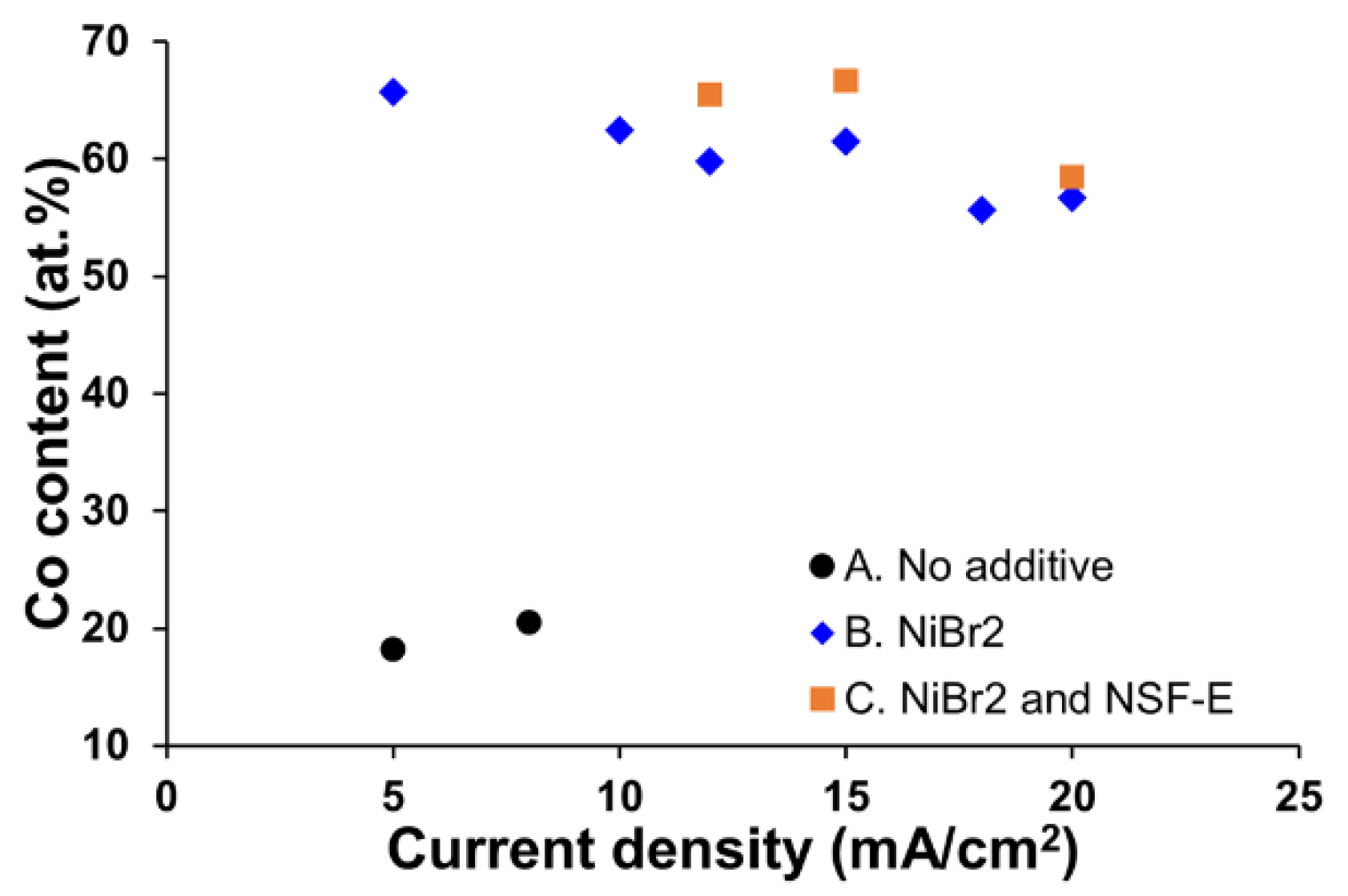
3.3. Composition
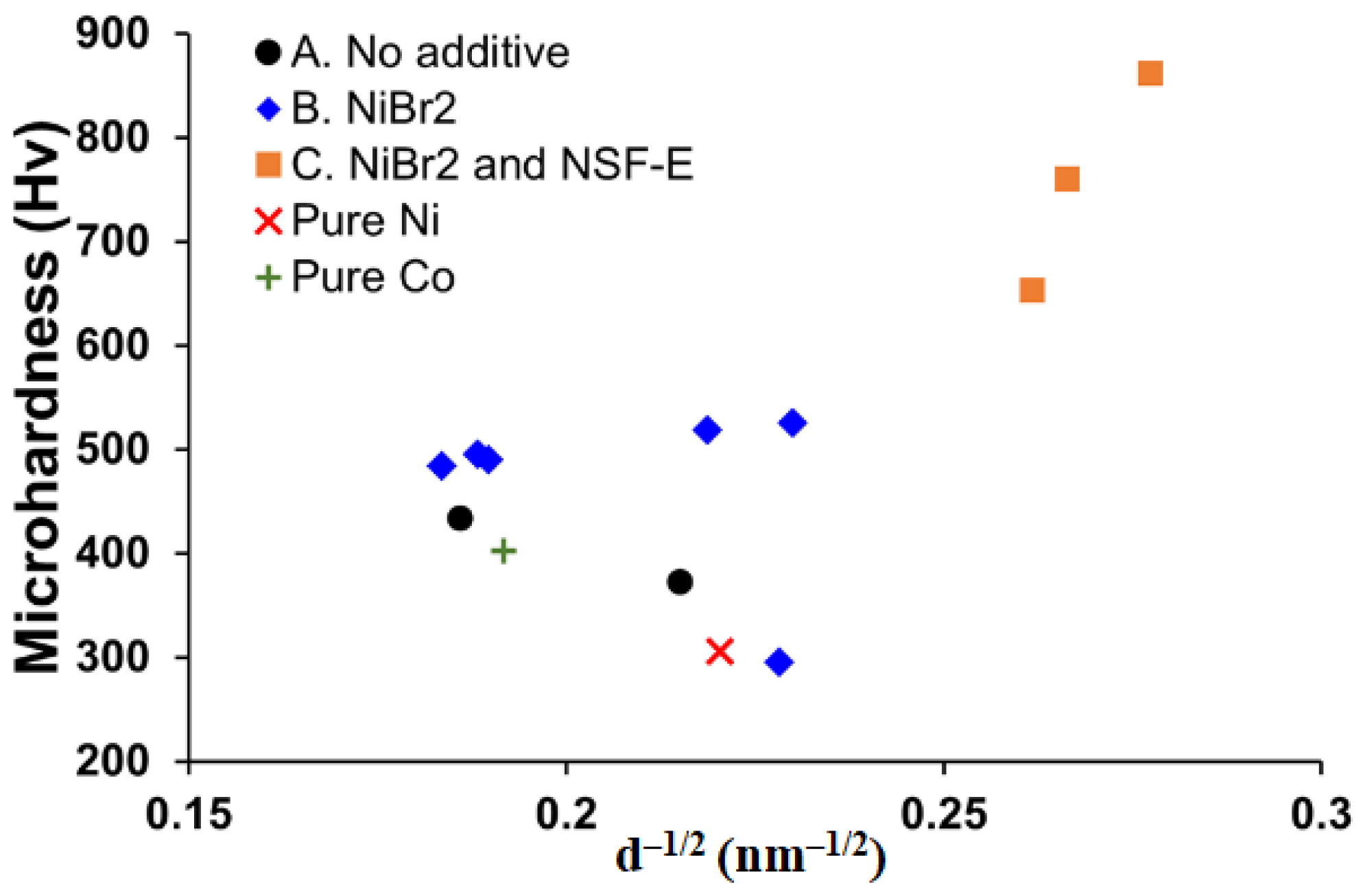
3.4. Microhardness
4. Conclusions
Author Contributions
Funding
Institutional Review Board Statement
Informed Consent Statement
Data Availability Statement
Conflicts of Interest
References
- Yamamoto, T.; Igawa, K.; Tang, H.C.; Chen, C.Y.; Chang, T.F.M.; Nagoshi, T.; Kudo, O.; Maeda, R.; Sone, M. Effects of current density on mechanical properties of electroplated nickel with high speed sulfamate bath. Microelectron. Eng. 2019, 213, 18–23. [Google Scholar] [CrossRef]
- Luo, X.; Chen, C.Y.; Chang, T.F.M.; Hosoda, H.; Sone, M. Crystal growth of cobalt film fabricated by electrodeposition with dense carbon dioxide. J. Electrochem. Soc. 2015, 162, D423–D426. [Google Scholar] [CrossRef]
- Cole, K.M.; Kirk, D.W.; Thorpe, S.J. In Situ Raman Study of Amorphous and Crystalline Ni-Co Alloys for the Alkaline Oxygen Evolution Reaction. J. Electrochem. Soc. 2018, 165, J3122–J3129. [Google Scholar] [CrossRef]
- Duch, M.; Esteve, J.; Gómez, E.; Pérez-Castillejos, R.; Vallés, E. Electrodeposited Co-Ni alloys for MEMS. J. Micromech. Microeng. 2002, 12, 400–405. [Google Scholar] [CrossRef]
- Chen, C.Y.; Yoshiba, M.; Nagoshi, T.; Chang, T.F.M.; Yamane, D.; Machida, K.; Masu, K.; Sone, M. Pulse electroplating of ultra-fine grained Au films with high compressive strength. Electrochem. Commun. 2016, 67, 51–54. [Google Scholar] [CrossRef] [Green Version]
- Hughes, G.D.; Smith, S.D.; Pande, C.S.; Johnson, H.R.; Armstrong, R.W. Hall-petch strengthening for the microhardness of twelve nanometer grain diameter electrodeposited nickel. Scr. Metall. 1986, 20, 93–97. [Google Scholar] [CrossRef]
- Hall, E.O. The Deformation and Ageing of Mild Steel: III Discussion of Results. Proc. Phys. Soc. Lond. Sect. B 1951, 64, 747–753. [Google Scholar] [CrossRef]
- Petch, N.J. The orientation relationships between cementite and α-iron. Acta Cryst. 1953, 6, 96. [Google Scholar] [CrossRef] [Green Version]
- Sriraman, K.R.; Raman, S.G.S. Synthesis and evaluation of hardness and sliding wear resistance of electrodeposited nanocrystalline Ni–W alloys. Mater. Sci. Eng. A 2006, 418, 303–311. [Google Scholar] [CrossRef]
- Giga, A.; Kimoto, Y.; Takigawa, Y.; Higashi, K. Demonstration of an inverse Hall–Petch relationship in electrodeposited nanocrystalline Ni–W alloys through tensile testing. Scr. Mater. 2006, 55, 143–146. [Google Scholar] [CrossRef]
- Li, Y.; Jiang, H.; Huang, H. Effects of peak current density on the mechanical properties of nanocrystalline Ni–Co alloys produced by pulse electrodeposition. Appl. Surf. Sci. 2008, 254, 6865–6869. [Google Scholar] [CrossRef]
- Tang, H.; Chang, T.F.M.; Chai, Y.W.; Chen, C.Y.; Nagoshi, T.; Yamane, D.; Ito, H.; Machida, K.; Masu, K.; Sone, M. Nanoscale Hierarchical Structure of Twins in Nanograins Embedded with Twins and the Strengthening Effect. J. Electrochem. Soc. 2018, 165, D58–D63. [Google Scholar] [CrossRef]
- Schuh, C.A.; Nieh, T.G.; Iwasaki, H. The effect of solid solution W additions on the mechanical properties of nanocrystalline Ni. Acta Mater. 2003, 51, 431–443. [Google Scholar] [CrossRef]
- Han, B.Q.; Lavernia, E.J. Deformation Mechanisms of Nanostructured Al Alloys. Adv. Eng. Mater. 2005, 7, 457–465. [Google Scholar] [CrossRef]
- Bai, A.; Hu, C.C. Effects of electroplating variables on the composition and morphology of nickel–cobalt deposits plated through means of cyclic voltammetry. Electrochim. Acta 2002, 47, 3447–3456. [Google Scholar] [CrossRef]
- Hu, C.C.; Wang, C.K. Effects of composition and reflowing on the corrosion behavior of Sn–Zn deposits in brine media. Electrochim. Acta 2006, 51, 4125–4134. [Google Scholar] [CrossRef]
- Tudela, I.; Zhang, Y.; Pal, M.; Kerr, I.; Cobley, A.J. Ultrasound-assisted electrodeposition of composite coatings with particles. Surf. Coat. Technol. 2014, 259, 363–373. [Google Scholar] [CrossRef]
- Kolonits, T.; Czigány, Z.; Péter, L.; Bakonyi, I.; Gubicza, J. Influence of bath additives on the thermal stability of the nanostructure and hardness of Ni films processed by electrodeposition. Coatings 2019, 9, 644. [Google Scholar] [CrossRef] [Green Version]
- Chang, T.F.M.; Sone, M.; Shibata, A.; Ishiyama, C.; Higo, Y. Bright nickel film deposited by supercritical carbon dioxide emulsion using additive-free Watts bath. Electrochim. Acta 2010, 55, 6469–6475. [Google Scholar] [CrossRef]
- Park, D.-Y.; Park, K.S.; Ko, J.M.; Cho, D.-H.; Lim, S.H.; Kim, W.Y.; Yoo, B.Y.; Myung, N.V. Electrodeposited Ni1−xCox Nanocrystalline Thin Films: Structure–Property Relationships. J. Electrochem. Soc. 2006, 153, C814–C821. [Google Scholar] [CrossRef]
- Myung, N.V.; Park, D.Y.; Yoo, B.Y.; Sumodjo, P.T.A. Development of electroplated magnetic materials for MEMS. J. Magn. Magn. Mater. 2003, 265, 189–198. [Google Scholar] [CrossRef]
- Nitta, K.; Chang, T.F.M.; Tang, H.; Chen, C.Y.; Iida, S.; Yamane, D.; Machida, K.; Ito, H.; Masu, K.; Sone, M. Alloy electroplating and Young’s modulus characterization of AuCu alloy microcantilevers. J. Electrochem. Soc. 2020, 167, 082503. [Google Scholar] [CrossRef]
- Shi, L.; Sun, C.; Liu, W. Electrodeposited nickel–cobalt composite coating containing MoS2. Appl. Surf. Sci. 2008, 254, 6880–6885. [Google Scholar] [CrossRef]
- Sau, T.K.; Rogach, A.L. Nonspherical noble metal nanoparticles: Colloid-chemical synthesis and morphology control. Adv. Mater. 2010, 22, 1781–1804. [Google Scholar] [CrossRef]
- Tsuru, Y.; Nomura, M.; Foulkes, F.R. Effects of chloride, bromide and iodide ions on internal stress in films deposited during high speed nickel electroplating from a nickel sulfamate bath. J. Appl. Electrochem. 2000, 30, 231–238. [Google Scholar] [CrossRef]
- Huynh, T.M.T.; Wess, F.; Hai, N.T.M.; Reckien, W.; Bredow, T.; Fluegel, A.; Arnold, M.; Mayer, D.; Keller, H.; Broekmann, P. On the role of halides and thiols in additive-assisted copper electroplating. Electrochim. Acta 2013, 89, 537–548. [Google Scholar] [CrossRef]
- Moti, E.; Shariat, M.H.; Bahrololoom, M.E. Influence of cathodic overpotential on grain size in nanocrystalline nickel deposition on rotating cylinder electrodes. J Appl. Electrochem. 2008, 38, 605–612. [Google Scholar] [CrossRef]
- Vanýsek, P. Electrochemical series. In Handbook of Chemistry and Physics, 93th ed.; Haynes, W.M., Ed.; CRC Press: New York, NY, USA, 2012; pp. 5–88. [Google Scholar]
- Burzyńska, L.; Rudnik, E. The influence of electrolysis parameters on the composition and morphology of Co–Ni alloys. Hydrometallurgy 2000, 54, 133–149. [Google Scholar] [CrossRef]


| Current Density (mA/cm2) | Grain Size (nm) | Co Content (at.%) | Microhardness (Hv) | Sample No. | |
|---|---|---|---|---|---|
| Without additive | 5 | 21.6 | 18.19 | 372.4 ± 12.2 | A1 |
| 8 | 28.9 | 20.45 | 433.4 ± 11.3 | A2 | |
| With NiBr2 | 5 | 19.2 | 65.74 | 295.6 ± 5.9 | B1 |
| 10 | 18.9 | 62.48 | 526.0 ± 7.2 | B2 | |
| 12 | 29.7 | 59.82 | 484.4 ± 15.2 | B3 | |
| 15 | 27.8 | 61.51 | 490.2 ± 12.0 | B4 | |
| 18 | 28.2 | 55.63 | 495.6 ± 14.8 | B5 | |
| 20 | 20.9 | 56.67 | 519.0 ± 15.4 | B6 | |
| With NiBr2 and NSF-E | 12 | 14.1 | 65.47 | 760.2 ± 14.2 | C1 |
| 15 | 13.0 | 66.64 | 862.2 ± 11.5 | C2 | |
| 20 | 14.6 | 58.48 | 653.4 ± 15.5 | C3 | |
| Pure Ni | 10 | 20.6 | 0 | 305.8 ± 11.1 | Ni |
| Pure Co | 10 | 27.2 | 100 | 402.6 ± 16.9 | Co |
Publisher’s Note: MDPI stays neutral with regard to jurisdictional claims in published maps and institutional affiliations. |
© 2020 by the authors. Licensee MDPI, Basel, Switzerland. This article is an open access article distributed under the terms and conditions of the Creative Commons Attribution (CC BY) license (http://creativecommons.org/licenses/by/4.0/).
Share and Cite
Jiang, Y.; Chen, C.-Y.; Chang, T.-F.M.; Luo, X.; Yamane, D.; Sone, M. Electrodeposition of Ni-Co Alloys and Their Mechanical Properties by Micro-Vickers Hardness Test. Electrochem 2021, 2, 1-9. https://0-doi-org.brum.beds.ac.uk/10.3390/electrochem2010001
Jiang Y, Chen C-Y, Chang T-FM, Luo X, Yamane D, Sone M. Electrodeposition of Ni-Co Alloys and Their Mechanical Properties by Micro-Vickers Hardness Test. Electrochem. 2021; 2(1):1-9. https://0-doi-org.brum.beds.ac.uk/10.3390/electrochem2010001
Chicago/Turabian StyleJiang, Yiming, Chun-Yi Chen, Tso-Fu Mark Chang, Xun Luo, Daisuke Yamane, and Masato Sone. 2021. "Electrodeposition of Ni-Co Alloys and Their Mechanical Properties by Micro-Vickers Hardness Test" Electrochem 2, no. 1: 1-9. https://0-doi-org.brum.beds.ac.uk/10.3390/electrochem2010001