Article

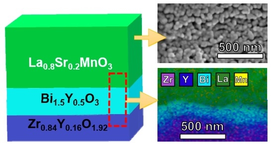
Influence of Bi1.5Y0.5O3 Active Layer on the Performance of Nanostructured La0.8Sr0.2MnO3 Cathode

by
Javier Zamudio-García
1,*,
Nerea Albarrán-Aroca
2,
José M. Porras-Vázquez
1,
Enrique R. Losilla
1 and
David Marrero-López
2,*
1
Deparment of Inorganic Chemistry, University of Málaga, 29071 Málaga, Spain
2
Department of Applied Physics I, University of Málaga, 29071 Málaga, Spain
*
Authors to whom correspondence should be addressed.
Submission received: 8 August 2020 / Revised: 21 August 2020 / Accepted: 27 August 2020 / Published: 1 September 2020
(This article belongs to the Special Issue Nanomaterials for Solid Oxide Cell Applications)

Abstract

:
The efficiency of solid oxide fuel cell cathodes can be improved by microstructural optimization and using active layers, such as doped bismuth oxides. In this work, Bi1.5Y0.5O3 (BYO) films are prepared by spray-pyrolysis deposition at reduced temperatures on a Zr0.84Y0.16O1.92 (YSZ) electrolyte. The influence of the BYO film on the performance of an La0.8Sr0.2MnO3 (LSM) cathode prepared by traditional screen-printing and spray-pyrolysis is investigated. A complete structural, morphological, and electrochemical characterization is carried out by X-ray diffraction, electron microscopy, and impedance spectroscopy. The incorporation of BYO films decreases the Area Specific Resistance (ASR) of screen-printed cathodes from 6.4 to 2.2 Ω cm2 at 650 °C. However, further improvements are observed for the nanostructured electrodes prepared by spray-pyrolysis with ASRs of 0.55 and 1.15 Ω cm2 at 650 °C for cathodes with and without an active layer, respectively. These results demonstrate that microstructural control using optimized fabrication methods is desirable to obtain high-efficiency electrodes for solid oxide fuel cell (SOFC) applications.

Graphical Abstract

1. Introduction

Solid oxide fuel cells (SOFCs) are considered a highly promising technology for clean and efficient power generation [1,2]. However, several issues should be addressed, such as the reduction in the current operating temperature to an intermediate range of 500–750 °C to promote their development and commercialization. In particular, the cell efficiency at low temperatures is mainly limited by the oxygen reduction reaction (ORR) in the cathode [3].
La1−xSrxMnO3 (LSM) is still the most widely used cathode material due to its high chemical and thermal stability under the severe operating conditions of the cell, as well as excellent compatibility with the common electrolyte material, yttria stabilized zirconia (YSZ) [4,5]. However, LSM exhibits a poor ionic conductivity and relatively high activation energy for the oxygen reduction reaction, reducing drastically its electrochemical performance at intermediate temperatures [6,7]. Different strategies have been explored to overcome this limitation: (i) combining LSM with ionic conducting materials, such as YSZ, doped-CeO2, and Bi2O3-based electrolytes [8,9,10]; (ii) the preparation of nanostructured LSM cathodes with an extended triple-phase boundary (TPB) for the oxygen reduction reaction [7,11]; and (iii) the introduction of an active interlayer with a high ionic conductivity to enhance the oxide ion transfer from the cathode to the electrolyte [12,13].
Bismuth oxide stabilized with Er3+ or Y3+ has showed to be an effective active layer due to its superior oxide ion conductivity compared to YSZ and doped-CeO2 [14,15]. These active layers are traditionally prepared by screen-printing [16,17] and dip-coating [18,19] at high sintering temperatures for long times to achieve both dense films and a good adhesion to the electrolyte. However, Bi evaporates at a relatively low temperature, and therefore low-temperature fabrication methods are needed. Physical deposition methods, such as pulsed laser deposition [20,21] and magnetron-sputtering [14,22], have been also employed; nevertheless, these methods are not economic for industrial implementation. In this context, spray-pyrolysis has shown to be an effective method for the preparation of different materials for SOFCs, including electrolytes, electrodes, and barrier layers [23,24]. This method has several advantages, including the preparation of material layers in a single deposition/sintering step, its low cost, its shorter preparation time, and its easy implementation at industrial scale as a continuous process over large surfaces. Moreover, the sintering temperature is significantly reduced, minimizing the chemical reactivity between the cell components.
In this work, nanostructured LSM cathodes with and without Bi1.5Y0.5O3 (BYO) active layers are obtained by spray-pyrolysis deposition. The structure and morphology of the layers are studied by X-ray diffraction and scanning electron microscopy, respectively. An exhaustive electrochemical characterization by impedance spectroscopy is carried out at different temperatures and oxygen partial pressures to determine the different processes involved in the ORR, as well as the effect of the BYO layer on the efficiency of LSM cathodes. The results are compared with those obtained for traditional cathodes fabricated by the screen-printing method.

2. Materials and Methods

Zr0.84Y0.16O1.92 (YSZ) pellets were prepared from commercial powders supplied by Tosoh. These were compacted into disks of 10 and 1 mm diameter and thickness, respectively, and then sintered in air at 1400 °C for 4 h to obtain fully dense electrolytes.
For the preparation of the Bi1.5Y0.5O3 (BYO) layers by spray-pyrolysis, stoichiometric amounts of Bi(NO3)3·6H2O and Y(NO3)3·6H2O (Merck, purity above 99%) were dissolved in Milli-Q water under continuous stirring to form a yellow transparent solution with a cation concentration of 0.01 mol L−1. Citric acid was used as a complexing agent in a relation of ligand:metal of 0.5:1 to prevent phase segregations. Films prepared without citric acid were a mixture of monoclinic and cubic polymorphs of Bi2O3. The spray-pyrolysis setup and deposition conditions were similar to those described previously for related materials [11]. Briefly, the YSZ substrates were previously heated at 450 °C, and then the precursor solution was atomized and sprayed onto both pellet faces for 15 min with a flow rate of 20 mL h−1. After that, the films were calcined between 600 and 800 °C for 1 h in a furnace to achieve crystallization.
The La0.8Sr0.2MnO3 (LSM) cathode was deposited by spray-pyrolysis onto YSZ substrates with and without BYO interlayers from an aqueous precursor solution (0.02 mol L−1), containing stoichiometric amounts of La(NO3)3·6H2O, Sr(NO3)2, and Mn(NO3)2·4H2O (Merck, purity above 99%). This precursor solution was sprayed onto the YSZ and YSZ/BYO substrates, preheated at 250 °C, for 1 h with a flow rate of 20 mL h−1 [7]. Finally, the samples were calcined in a furnace to completely decompose the precursors and crystallize the cathodes at 800 °C for 1 h. Hereafter, the samples prepared by spray-pyrolysis are labelled with SP.
For comparison purposes, commercial La0.8Sr0.2MnO3-δ (LSM) powders supplied by Praxair® were mixed with Decoflux binder to obtain an ink, which was screen-printed onto the as-prepared YSZ substrates and BYO active layers, followed by sintering at 1000 °C for 1 h to ensure sufficient adherence.

Structural, Microstructural, and Electrical Characterization

The phase composition and structure were studied by X-ray powder diffraction (XRD) with an Empyrean PANalytical diffractometer and CuKα1,2 radiation. The different phases were identified and analyzed with the Highscore Plus and GSAS suite software [25,26].
The morphology and elemental analysis of the different samples were analyzed by field emission scanning electron microscopy in a FEI-SEM (Helios Nanolab 650) coupled with X-ray dispersive spectroscopy (EDS, X-Max Oxford instrument, High Wycombe, UK).
The impedance spectra of the symmetrical cells were collected with a Solartron 1260. The frequency range and the AC amplitude applied were 0.01–106 Hz and 100 mV, respectively. Pt-ink (METALOR® 6082) was painted on both faces of the pellets and then heated at 750 °C for 30 min to obtain a current collector layer. Furthermore, the impedance spectra were collected as a function of the oxygen partial pressure (10−3–1 atm) at 650 °C to study the different processes involved in the ORR. The data were simulated by equivalent circuit models and the distribution of relaxation times (DRT) with the help of the ZView and DRTtools software, respectively [27,28].

3. Results and Discussion

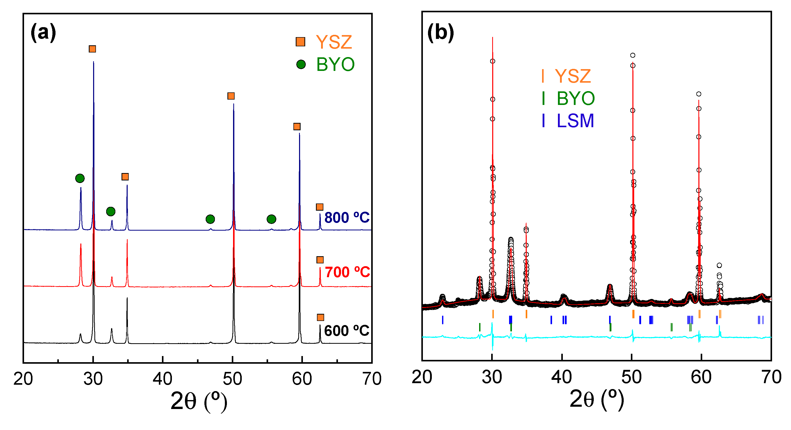
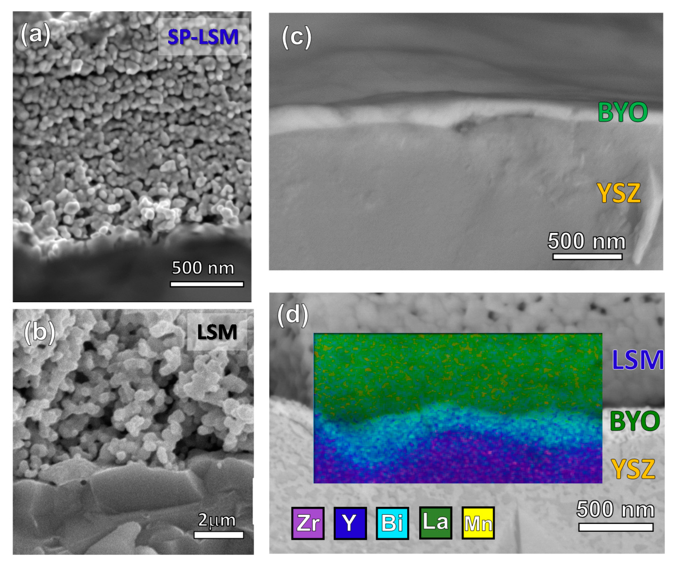
3.1. Structural and Microstructural Analysis

The XRD patterns of BYO films prepared by spray-pyrolysis onto YSZ substrates at 450 °C for 15 min and then calcined at different temperatures are compared in Figure 1a. The different reflections are assigned to the YSZ substrate and the BYO film, both with a cubic fluorite-type structure. The BYO film shows a higher crystallinity as the temperature increases, and more importantly no additional peaks attributed to secondary phases are detected up to 800 °C. In addition, no appreciable shift of the diffraction peaks is observed, indicating that the cell volume and structure are not affected by the thermal treatment. The estimated average crystal size of BYO, calculated by the Scherrer equation after correction for instrumental broadening, increases from 26 nm at 600 °C to 47 nm at 800 °C. These values are relatively low in comparison with those obtained by conventional preparation methods, such as screen-printing (e.g., 500 nm for films deposited at 800 °C for 2 h [14]), due to the shorter sintering time and low temperature used in this work, which inhibit the grain growth.
Figure 1b shows the XRD Rietveld analysis of the LSM cathode deposited by spray-pyrolysis on the BYO/YSZ substrate after calcining at 800 °C. Three different crystalline phases, assigned to the YSZ electrolyte, the BYO active layer, and the LSM cathode, are observed without the presence of secondary phases. The Rietveld analysis is performed by considering two cubic fluorite-type phases (s.g. Fm-3m) for both YSZ and BYO and a rhombohedral structure (s.g. R-3c) for LSM, obtaining a successful disagreement factor: Rwp = 5.15% (Figure 1b). The unit cell volumes for BYO and LSM are 164.275(2) and 350.357(1) Å3, respectively, in good agreement with those reported in the literature for the bulk materials [7,29].
Cross-sectional SEM images of the symmetrical cells are displayed in Figure 2. The LSM cathode prepared by spray-pyrolysis at 800 °C has a particle size of ~50 nm and is highly porous, ensuring effective gas diffusion inside the cathode (Figure 2a). In contrast, the LSM cathode prepared by the screen-printing method shows a large particle size of 500 nm due to the higher sintering temperature required to obtain a good adhesion to the electrolyte (Figure 2b).
A backscattering SEM image reveals that the BYO films are dense with a thickness of ~200 nm and a good adhesion to the electrolyte (Figure 2c). Furthermore, the BYO film covers uniformly the electrolyte surface without the presence of delaminations or cracks, confirming that spray-pyrolysis deposition is a useful method for the preparation of BYO films at low temperatures. EDS analysis after LSM deposition shows clearly the elemental distribution of the different layers without appreciable cation interdiffusion between the cell components (Figure 2d). Furthermore, the theoretical and experimental cation compositions of the different layers are similar (Supplementary Information Tables S1–S3).

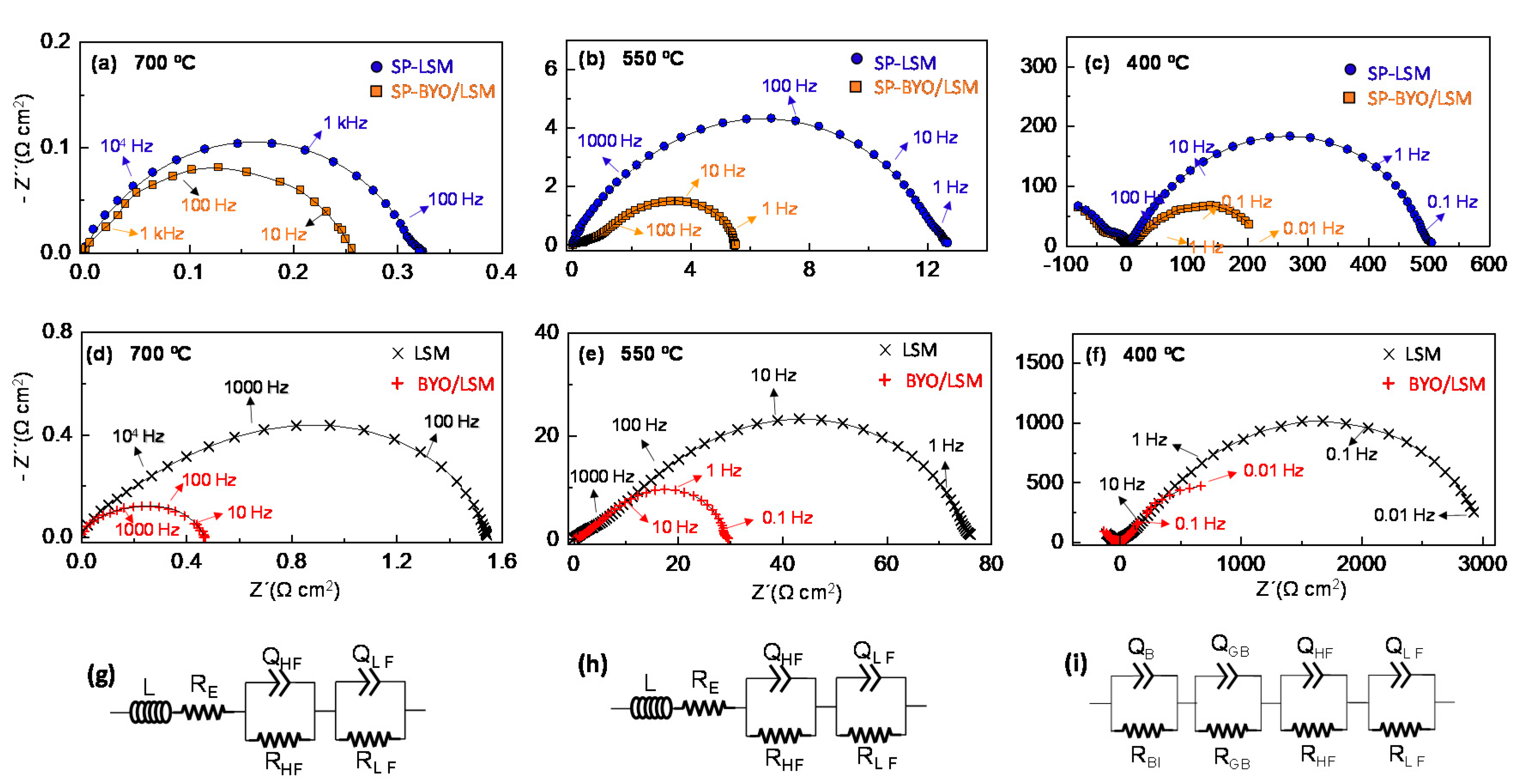
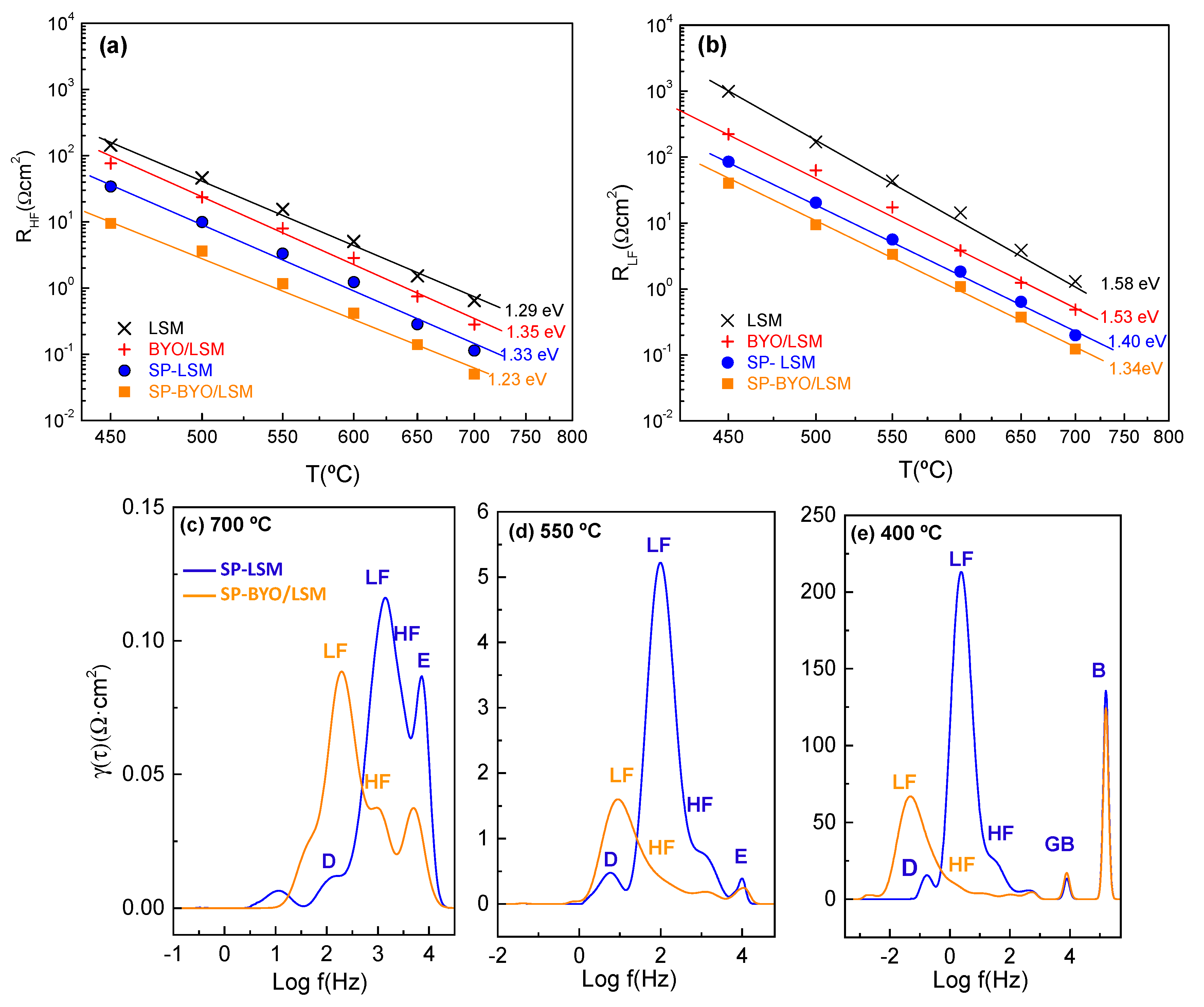
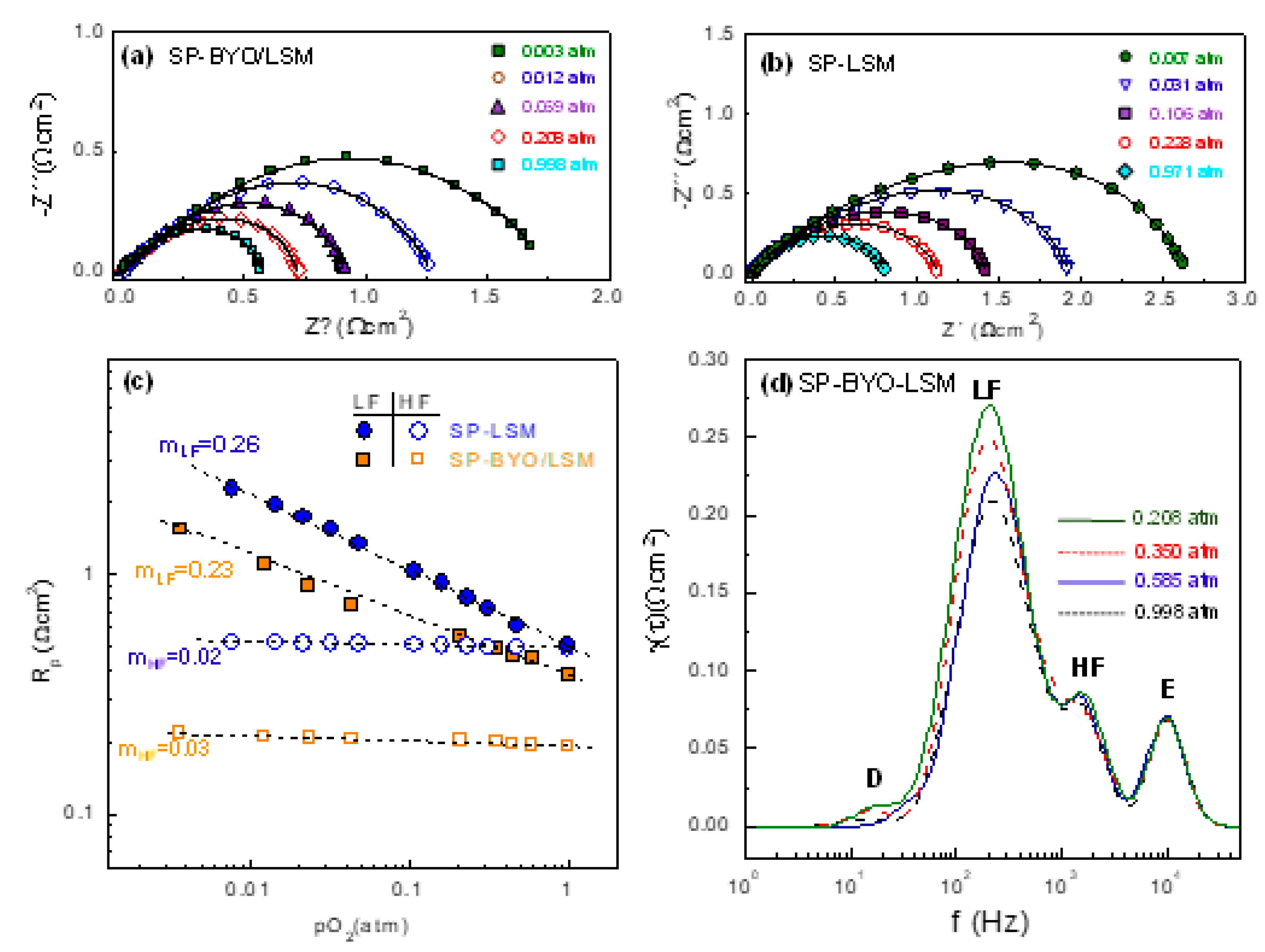
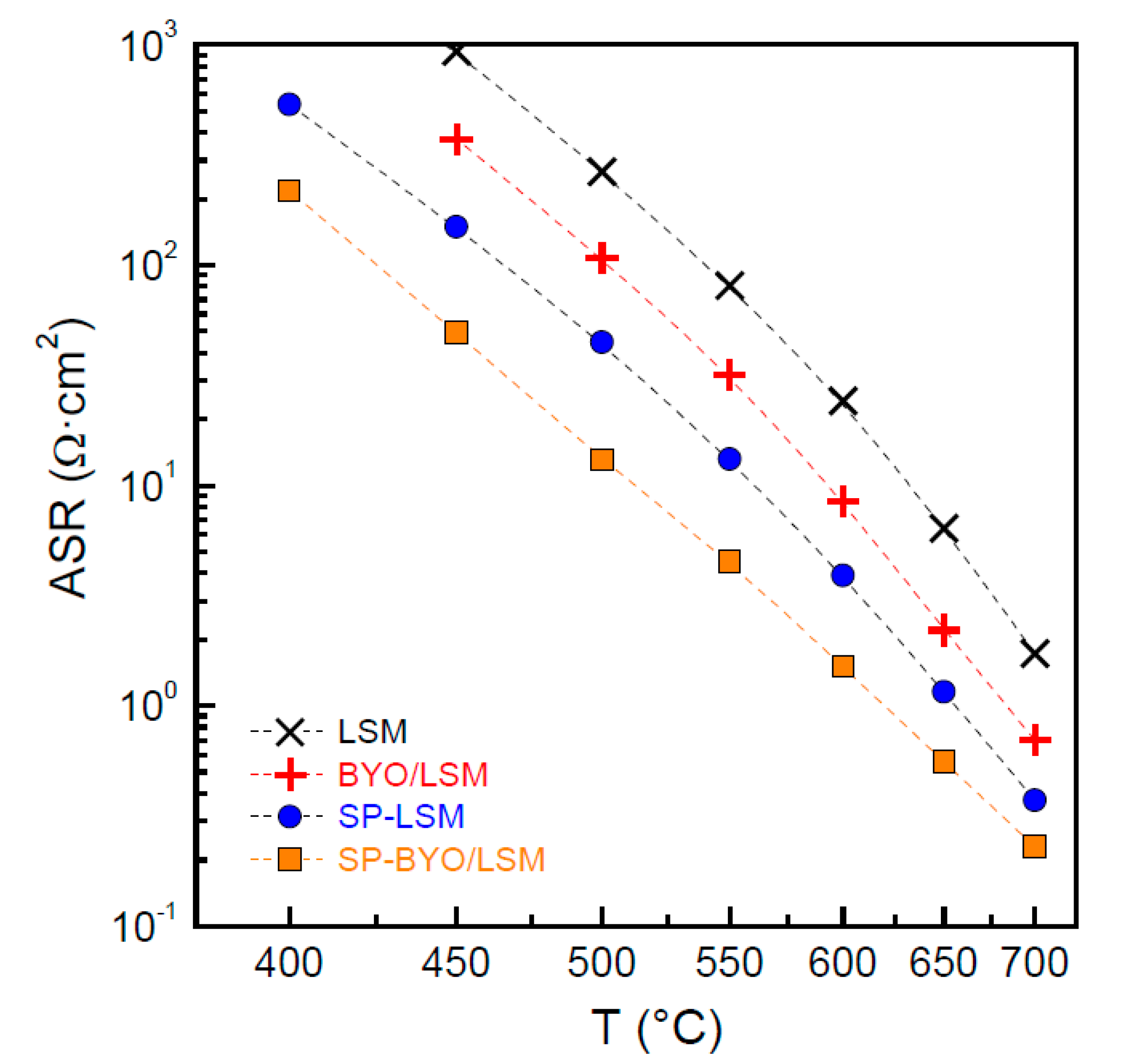
3.2. Electrochemical Properties

Figure 3a–c show the impedance spectra for the different symmetrical cells prepared by spray-pyrolysis deposition on YSZ substrates without and with a BYO active layer. For comparison purposes, Figure 3d–f show the spectra for the same symmetrical cell with LSM deposited by the traditional screen-printing method. Note that the ohmic resistances were subtracted for a better comparison of the electrode contribution. All the spectra were fitted using the equivalent circuits given in Figure 3g–i, where L is an inductor attributed to the electrochemical setup and RE is a serial resistance related with the total ohmic resistance of the electrolyte. Two serial (RQ) elements, where R is the resistance in parallel with a constant phase element Q, are included to model the electrode response at high frequency and low frequency, HF and LF, respectively. The high-frequency process is typically associated with charge transfer at the electrolyte/electrode interface, while the low frequency contribution is assigned to the absorption/dissociation of oxygen molecules at the LSM cathode surface [7]. In the low temperature range (T < 450 °C), the bulk (B) and grain boundary contributions (GB) of the electrolyte are discernible, and the equivalent circuit of Figure 3i was considered.
The following parameters were obtained for each electrode contribution: resistance Ri, pseudocapacitance Qi, and the exponential parameter ni. These parameters are related to the true capacitance Ci and relaxation frequency fi by the following equations [23]:
C i = ( R i Q i ) 1 / n i R
f i = 1 2 π R i C i
The representative fitting parameters obtained by equivalent circuits are given in Table S4.
The impedance spectra confirm that the total electrode polarization resistance is lower for all cells containing the BYO active layer. A detailed analysis of the data reveals that the high-frequency process decreases significantly after the introduction of the BYO interlayer due to the improved oxide ion transfer at the electrolyte/interface (Figure 4a). A similar behavior was reported for other active layers—e.g., Ce0.1Gd0.1O1.95, Ce0.9Pr0.1O1.95, and SrFeO3 [12,30,31,32,33]. The corresponding activation energy varies between 1.23 and 1.35 eV.
In the case of the LF process, a similar behavior is observed, where the resistance decreases with the introduction of the BYO layer (Figure 4b). This indicates that the BYO layer not only improves the charge transfer due to better oxide-ionic conduction at the interface, but also promotes the extension of the surface path of the electrochemical reaction sites to the active interlayer. Furthermore, the activation energy of the LF process is higher than that of the HF process, and varies in a broad range from 1.58 eV for LSM to 1.34 eV for SP-LSM/BYO.
The DRT analysis confirms that the cathode response is formed by two main electrode contributions, attributed to the oxide ion transfer between the cathode/electrolyte interface and the oxygen surface exchange process at a high (HF) and low (LF) frequency, respectively (Figure 4c–e) [34]. In addition, a small process due to gas diffusion limitations into the electrode, labelled as D, has been identified at a low frequency [35]. It has to be noted that the integral area under each peak is equivalent to the polarization resistance of the corresponding process [36].
It is also observed that the introduction of the BYO active layer involves a displacement of the electrode contribution to lower frequencies, attributed to the fast oxide ion conductivity of the bismuth oxide layers [37,38]. The LF process is the main contribution in the whole temperature range, although it decreases significantly at high temperatures due to the higher activation energy of the oxygen exchange process. The process centered at 104 Hz is assigned to the ohmic resistance of the electrolyte (E) (Figure 4c,d). In the low temperature range (T ≤ 400 °C), the two contributions located at 104 and 105 Hz correspond to the bulk (B) and grain boundary (GB) contributions of the electrolyte, respectively (Figure 4e) [39]. As expected, the electrolyte contributions are not affected by the presence of the BYO layer, and they appear at the same frequency for cathodes with and without an active layer. The shift of the electrode processes to lower frequencies after the BYO introduction is consistent with the equivalent circuit analysis, where the capacitances of the HF and LF processes increase in two orders of magnitude in cathodes containing the active layers. This increase in capacitance is usually related to an increase in active sites for the ORR; a similar behavior has been observed for nanostructured electrodes [7].
In order to obtain further insights into the rate-limiting-steps involved in the ORR, the impedance spectra were acquired as a function of the oxygen partial pressure (pO2). Figure 5a,b display the variation of the impedance spectra of SP-LSM and SP-BYO/LSM. As expected, the polarization resistance increases at low oxygen partial pressure, but the number of processes remains unchanged. Hence, the equivalent circuit proposed above (Figure 3g–i) is used to fit the data in the whole pO2 range. The resistance of the different processes, which involves surface adsorption/dissociation, gas diffusion, or charge transfer reactions are pO2-dependent, according to the following expression [3,33]:
R i ( p O 2 ) m
where m provides information about the type of process involved in the oxygen reduction reactions. Figure 5c compares the variation in the HF and LF resistance contributions as a function of pO2. This figure clearly indicates that the low-frequency contribution is the main rate-limiting step for the ORR, especially at low pO2. For both samples, the HF contribution is nearly pO2-independent with a slope of m~0.02–0.03, suggesting that molecular or atomic oxygen are not involved in this process and, therefore, may be assigned to the O2− transfer at the YSZ/LSM interface. In contrast, the LF contribution with m∼0.25 is attributed to the charge-transfer reaction on the electrode surface [33].
The DRT analysis of the impedance spectra confirms that the electrolyte contribution (E) and the HF process of the electrode polarization are pO2-independent as expected; however, the LF process is affected by changes in the oxygen concentration (Figure 5d). At low pO2 values, a new process (D) appears at ~10 Hz, which could be assigned to gas diffusion limitations, as observed previously [35].
Figure 6 compares the area specific resistance (ASR) of the different cathodes. The highest ASR values are found for the blank LSM cathode prepared by the traditional screen printing method—i.e., 6.4 Ω cm2 at 650 °C. The introduction of a BYO active layer leads to a significant ASR decrease up to ~2.2 Ω cm2. However, nanostructured LSM cathodes prepared by spray-pyrolysis exhibit lower ASR values than those of the corresponding screen-printed cathodes—i.e., 1.15 and 0.55 Ω cm2 at 650 °C for SP-LSM and SP-BYO/LSM, respectively. This behavior is explained by the higher TPB length of the nanostructured LSM cathodes, as well as the lowest fabrication temperature, which minimize the reactivity between the cell layers. These results demonstrate that active layers could be used to improve the performance of SOFC cathodes; however, the optimization of the electrode microstructure leads to better electrochemical properties.

4. Conclusions

The influence of BYO active layer on the performance of micrometric and nanostructured LSM cathodes prepared by screen-printing and spray-pyrolysis deposition, respectively, was investigated.
Dense and thin BYO films were successfully prepared on YSZ electrolyte at a reduced temperature to avoid possible Bi loss by evaporation. The LSM cathode prepared by spray-pyrolysis deposition showed an average particle size of 50 nm compared to 500 nm for the screen-printing cathode, which leads to the extended triple-phase length for the ORR.
The analysis of the impedance spectra confirmed the presence of two dominant electrode processes for cathodes with and without BYO active layers, which were assigned to O2− transfer at the LSM/YSZ interface and the charge transfer reaction at the electrode surface. The introduction of a BYO layer decreased the resistances of both the high- and low-frequency contributions, suggesting that the active layer not only improves the charge transfer at the electrolyte interface but also extends the surface path of the electrochemical reaction sites.
The total polarization resistance for the different cathode configurations decreased in the order: LSM < LSM/BYO < SP-LSM < SP-BYO/LSM, indicating that the performance is further improved by increasing the electrode surface and TPB sites rather than the introduction of an active interlayer. Thus, the microstructural optimization is the most recommendable method to improve the efficiency of the SOFC cathodes and reduce the operating temperature of these electrochemical devices.

Supplementary Materials

The following are available online at https://0-www-mdpi-com.brum.beds.ac.uk/2673-3501/1/1/3/s1: Tables S1–S3: Cation composition of La0.8Sr0.2MnO3-δ, Bi1.5Y0.5O3-δ and Zr0.84Y0.16O3-δ layers, respectively. Table S4: Fitting parameters obtained by equivalent circuits.

Author Contributions

Conceptualization: J.Z.-G. and D.M.-L.; Methodology: J.Z.-G., J.M.P.-V.; Investigation: J.Z.-G., N.A.-A.; Formal analysis: J.Z.-G., J.M.P.-V., D.M.-L.; Validation: D.M.-L. and E.R.L.; Visualization: J.Z.-G. and D.M.-L.; Project administration: D.M.-L.; Writing-original draft: J.Z.-G. and D.M.-L.; review and editing: J.M.P.-V., N.A.-A., and E.R.L. All authors have read and agreed to the published version of the manuscript.

Funding

This research was funded by Ministerio de Ciencia, Innovación y Universidades (Spain), grant number RTI2018-093735-B-I00 and UMA18-FEDERJA-033.

Acknowledgments

J. Zamudio-García thanks to the Ministerio de Ciencia, Innovación y Universidades, for his FPU grant (FPU17/02621).

Conflicts of Interest

The authors declare no conflict of interest. The funders had no role in the design of the study; in the collection, analysis, or interpretation of data; in the writing of the manuscript; or in the decision to publish the results.

References

  1. Kan, W.H.; Samson, A.J.; Thangadurai, V. Trends in electrode development for next generation solid oxide fuel cells. J. Mater. Chem. A 2016, 4, 17913–17932. [Google Scholar] [CrossRef] [Green Version]
  2. Gao, Z.; Mogni, L.V.; Miller, E.C.; Railsback, J.G.; Barnett, S.A. A perspective on low-temperature solid oxide fuel cells. Energy Environ. Sci. 2016, 9, 1602–1644. [Google Scholar] [CrossRef]
  3. Adler, S.B. Factors governing oxygen reduction in solid oxide fuel cell cathodes. Chem. Soc. Rev. 2004, 104, 4791–4844. [Google Scholar] [CrossRef] [PubMed]
  4. Murray, E.P.; Tsai, T.; Barnett, S.A. Oxygen transfer processes in (La,Sr)MnO3/Y2O3-stabilized ZrO2 cathodes: An impedance spectroscopy study. Solid State Ion. 1998, 110, 235–243. [Google Scholar] [CrossRef]
  5. Minh, Q.; Takahashi, T. Science and Technology of Ceramic Fuel Cell; Elsevier: New York, NY, USA, 1995. [Google Scholar]
  6. Painter, A.S.; Huang, Y.L.; Wachsman, E.D. Durability of (La0.8Sr0.2)0.95MnO3-δ-(Er0.2Bi0.8)2O3 composite cathodes for low temperature SOFCs. J. Power Sources 2012, 220, 324–330. [Google Scholar] [CrossRef]
  7. Marrero-López, D.; Dos Santos-Gómez, L.; Canales-Vázquez, J.; Martín, F.; Ramos-Barrado, J.R. Stability and performance of nanostructured La0.8Sr0.2MnO3 cathodes deposited by spray-pyrolysis. Electrochim. Acta 2014, 134, 159–166. [Google Scholar] [CrossRef]
  8. Pajot, M.; Duffort, V.; Capoen, E.; Mamede, A.-S.; Vannier, R.-N. Influence of the strontium content on the performance of La1-xSrxMnO3/Bi1.5Er0.5O3 composite electrodes for low temperature Solid Oxide Fuel Cells. J. Power Sources 2020, 450, 227649. [Google Scholar] [CrossRef]
  9. Backhaus-Ricoult, M. Interface chemistry in LSM–YSZ composite SOFC cathodes. Solid State Ion. 2006, 177, 2195–2200. [Google Scholar] [CrossRef]
  10. Dos Santos-Gómez, L.; Zamudio-García, J.; Porras-Vázquez, J.M.; Losilla, E.R.; Marrero-López, D. Highly efficient La0.8Sr0.2MnO3-δ-Ce0.9Gd0.1O1.95 nanocomposite cathodes for solid oxide fuel cells. Ceram. Int. 2018, 44, 4961–4966. [Google Scholar] [CrossRef]
  11. Dos Santos-Gómez, L.; Losilla, E.R.; Martín, F.; Ramos-Barrado, J.R.; Marrero-López, D. Novel microstructural strategies to enhance the electrochemical performance of La0.8Sr0.2MnO3-δ cathodes. ACS Appl. Mater. Interfaces 2015, 7, 7197–7205. [Google Scholar] [CrossRef] [Green Version]
  12. Zapata-Ramírez, V.; Dos Santos-Gómez, L.; Mather, G.C.; Marrero-López, D.; Pérez-Coll, D. Enhanced Intermediate-Temperature Electrochemical Performance of Air Electrodes for Solid Oxide Cells with Spray-Pyrolyzed Active Layers. ACS Appl. Mater. Interfaces 2020, 12, 10571–10578. [Google Scholar] [CrossRef] [PubMed]
  13. Li, W.; Guan, B.; Ma, L.; Tian, H.; Liu, X. Synergistic Coupling of Proton Conductors BaZr0.1Ce0.7Y0.1Yb0.1O3-δ and La2Ce2O7 to Create Chemical Stable, Interface Active Electrolyte for Steam Electrolysis Cells. ACS Appl. Mater. Interfaces 2019, 11, 18323–18330. [Google Scholar] [CrossRef] [PubMed]
  14. Zhang, L.; Xia, C.; Zhao, F.; Chen, F. Thin film ceria–bismuth bilayer electrolytes for intermediate temperature solid oxide fuel cells with La0.85Sr0.15MnO3-δ–Y0.25Bi0.75O1.5 cathodes. Mater. Res. Bull. 2010, 45, 603–608. [Google Scholar] [CrossRef]
  15. Lee, K.T.; Jung, D.W.; Camaratta, M.A.; Yoon, H.S.; Ahn, J.S.; Wachsman, E.D. Gd0.1Ce0.9O1.95/Er0.4Bi1.6O3 bilayered electrolytes fabricated by a simple colloidal route using nano-sized Er0.4Bi1.6O3 powders for high performance low temperature solid oxide fuel cells. J. Power Sources 2012, 205, 122–128. [Google Scholar] [CrossRef]
  16. Leng, Y.J.; Chan, S.H. Anode-supported SOFCs with Y2O3-Doped Bi2O3/Gd2O3-Doped CeO2 composite electrolyte film. Electrochem. Solid State Lett. 2006, 9, A56. [Google Scholar] [CrossRef]
  17. Joh, D.W.; Park, J.H.; Kim, D.; Wachsman, E.D.; Lee, K.T. Functionally graded bismuth oxide/zirconia bilayer electrolytes for high-performance intermediate-temperature solid oxide fuel cells (IT-SOFCs). ACS Appl. Mater. Interfaces 2017, 9, 8443–8449. [Google Scholar] [CrossRef] [PubMed]
  18. Hou, J.; Liu, F.; Gong, Z.; Wu, Y.; Liu, W. Different ceria-based materials Gd0.1Ce0.9O2-δ and Sm0.075Nd0.075Ce0.85O2-δ for ceria–bismuth bilayer electrolyte high performance low temperature solid oxide fuel cells. J. Power Sources 2015, 299, 32–39. [Google Scholar] [CrossRef]
  19. Hou, J.; Bi, L.; Qian, J.; Zhu, Z.; Zhang, J.; Liu, W. High performance ceria–bismuth bilayer electrolyte low temperature solid oxide fuel cells (LT-SOFCs) fabricated by combining co-pressing with drop-coating. J. Mater. Chem. A 2015, 3, 10219–10224. [Google Scholar] [CrossRef] [Green Version]
  20. Ahn, J.S.; Camaratta, M.A.; Pergolesi, D.; Lee, K.T.; Yoon, H.; Lee, B.W.; Jung, D.W.; Traversa, E.; Wachsman, E.D. Development of High Performance Ceria/Bismuth Oxide Bilayered Electrolyte SOFCs for Lower Temperature Operation. J. Electrochem. Soc. 2010, 157, B376. [Google Scholar] [CrossRef]
  21. Park, J.Y.; Yoon, H.; Wachsman, E.D. Fabrication and characterization of high-conductivity bilayer electrolytes for intermediate temperature solid oxide fuel cells. J. Am. Ceram. Soc. 2005, 88, 2402–2408. [Google Scholar] [CrossRef]
  22. Zhang, L.; Li, L.; Zhao, F.; Chen, F.; Xia, C. Sm0.2Ce0.8O1.9/Y0.25Bi0.75O1.5 bilayered electrolytes for low-temperature SOFCs with Ag-Y0.25Bi0.75O1.5 composite cathodes. Solid State Ion. 2011, 192, 557–560. [Google Scholar] [CrossRef]
  23. Santos-Gómez, L.D.; Porras-Vázquez, J.M.; Losilla, E.R.; Marrero-López, D. Improving the efficiency of layered perovskite cathodes by microstructural optimization. J. Mater. Chem. A 2017, 5, 7896–7904. [Google Scholar] [CrossRef]
  24. Dos Santos-Gómez, L.; Zamudio-García, J.; Porras-Vázquez, J.M.; Losilla, E.R.; Marrero-López, D. Highly oriented and fully dense CGO films prepared by spray-pyrolysis and different precursor salts. J. Eur. Ceram. Soc. 2020, 40, 3080–3088. [Google Scholar] [CrossRef]
  25. X’Pert HighScore Plus; Malvern Panalytical: Almelo, The Netherlands, 2014.
  26. GSAS Program; Rep. No. LA-UR-86748; Los Alamos, National Lab: Los Alamos, NM, USA, 1994.
  27. Johnson, D. ZView: A Software Program for IES Analysis; Version 2.9; Scribner Associates, Inc.: Southern Pines, NC, USA, 2005. [Google Scholar]
  28. Wan, T.H.; Saccoccio, M.; Chen, C.; Ciucci, F. Influence of the Discretization Methods on the Distribution of Relaxation Times Deconvolution: Implementing Radial Basis Functions with DRTtools. Electrochim. Acta 2015, 184, 483–499. [Google Scholar] [CrossRef]
  29. Battle, P.D.; Catlow, C.R.A.; Heap, J.W.; Moroney, L.M. Structural and Dynamical Studies of δ-Bi2O3 Oxide Ion Conductors: I. The Structure of (Bi2O3)1−x(Y2O3)x as a Function of x and Temperature. J. Solid State Chem. 1986, 63, 8–15. [Google Scholar] [CrossRef]
  30. Gao, Z.; Zenou, V.Y.; Kennouche, D.; Marks, L.; Barnett, S.A. Solid oxide cells with zirconia/ceria Bi Layer electrolytes fabricated by reduced temperature firing. J. Mater. Chem. A 2015, 3, 9955–9964. [Google Scholar] [CrossRef]
  31. Molin, S.; Chrzan, A.; Karczewki, J.; Szymczewska, D.; Jasinki, P. The role of thin functional layers in solid oxide fuel cells, Electrochim. Acta 2016, 204, 136–145. [Google Scholar] [CrossRef]
  32. Pan, K.-J.; Hussain, A.M.; Huang, Y.-L.; Gong, Y.; Cohn, G.; Ding, D.; Wachsman, E.D. Evolution of Solid Oxide Fuel Cells via Fast Interfacial Oxygen Crossover. ACS Appl. Energy Mater. 2019, 2, 4069–4074. [Google Scholar] [CrossRef]
  33. Fleig, J. Solid oxide fuel cell cathodes: Polarization mechanisms and modeling of the electrochemical performance. Annu. Rev. Mater. Res. 2003, 33, 361–382. [Google Scholar] [CrossRef]
  34. Ghamarinia, M.; Babaei, A.; Zamani, C. Electrochemical characterization of La2NiO4-infiltrated La0.6Sr0.4Co0.2Fe0.8O3-d by analysis of distribution of relaxation times. Electrochim. Acta 2020, 353, 136520. [Google Scholar] [CrossRef]
  35. Kromp, A.; Leonide, A.; Weber, A.; Ivers-Tiffée, E. Electrochemical Analysis of Reformate-Fuelled Anode Supported SOFC. J. Electrochem. Soc. 2011, 158, B980. [Google Scholar] [CrossRef]
  36. Chen, Y.; Choi, Y.M.; Yoo, S.; Ding, Y.; Yan, R.; Pei, K.; Qu, C.; Zhang, L.; Chang, I.; Zhao, B.; et al. A highly efficient multi-phase catalyst dramatically enhances the rate of oxygen reduction. Joule 2018, 2, 938–949. [Google Scholar] [CrossRef]
  37. Lee, J.G.; Park, M.G.; Yoon, H.H.; Soul, Y.G. Application of GDC-YDB Bilayer and LSMYDB Cathode for Intermediate Temperature Solid Oxide Fuel Cells. J. Electroceram. 2013, 31, 231–237. [Google Scholar] [CrossRef]
  38. He, Z.; Ai, N.; He, S.; Jiang, S.P.; Zhang, L.; Rickard, W.D.A.; Tang, D.; Chen, K. Positive Effect of Incorporating Er0.4Bi1.6O3 on the Performance and Stability of La2NiO4+δ Cathode. J. Electrochem. Soc. 2019, 166, F796–F804. [Google Scholar] [CrossRef]
  39. Lenser, C.; Menzler, N.H. Impedance characterization of supported oxygen ion conducting electrolytes. Solid State Ion. 2019, 334, 70–81. [Google Scholar] [CrossRef]
Figure 1. X-ray diffraction patterns of (a) Bi1.5Y0.5O3 (BYO) films deposited on Zr0.84Y0.16O1.92 (YSZ) substrates after calcining at different temperatures, and (b) Rietveld analysis of La0.8Sr0.2MnO3 cathode deposited on BYO layer (SP-BYO/LSM).
Applnano 01 00003 g001
Figure 2. SEM image of (a) LSM cathode prepared by spray-pyrolysis; (b) LSM cathode prepared by screen-printing; (c) backscattering SEM, showing the dense BYO film deposited on the YSZ electrolyte; and (d) EDS mapping analysis of the different layers of the cells.
Applnano 01 00003 g002
Figure 3. Impedance spectra of LSM and BYO/LSM symmetrical cells with LSM prepared by (ac) spray-pyrolysis and (df) screen-printing at different measuring temperatures. (gi) Equivalent circuits used to fit the data. The solid lines in the spectra represent the fitting curve with the proposed equivalent circuits.
Applnano 01 00003 g003
Figure 4. Variation of the (a) high- and (b) low-frequency resistance contributions for the different cathode configurations; (ce) Distribution of relaxation time (DRT) analysis at different temperatures.
Applnano 01 00003 g004
Figure 5. Impedance spectra of (a) SP-BYO/LSM; (b) SP-LSM at 650 °C and different pO2; (c) dependence of the cathode resistance contributions on pO2; and (d) the DRT analysis of SP-BYO/LSM.
Applnano 01 00003 g005
Figure 6. Area specific resistance (ASR) values of the different LSM cathodes as a function of the temperature.
Applnano 01 00003 g006

