A LoRa-Based Linear Sensor Network for Location Data in Underground Mining


1
Faculty of Science, Engineering and Technology, Swinburne University of Technology, Melbourne 3122, VIC, Australia
2
Faculty of Engineering, University of New South Wales, Sydney 2052, NSW, Australia
*
Author to whom correspondence should be addressed.
†
Current address: Swinburne University of Technology, Melbourne 3122, VIC, Australia.
‡
These authors contributed equally to this work.
Telecom 2020, 1(2), 68-79; https://0-doi-org.brum.beds.ac.uk/10.3390/telecom1020006
Submission received: 28 May 2020
/
Revised: 25 June 2020
/
Accepted: 26 June 2020
/
Published: 6 July 2020
(This article belongs to the Special Issue Recent Advances in Smart and Pervasive Internet of Things)
Abstract
:In this paper, we describe a LoRa (from “Long Range”)-based, linear sensor network we have developed for transmitting location information of personnel and equipment in an underground mine. The system is intended to be used during emergencies when existing communications infrastructure has failed. Linear networks comprise a sequence of relays that forward data to a common destination, the headend. Relays forward location information transmitted from tags carried by personnel or equipment. Relays will usually be put in place as investigators or rescuers enter the mine. LoRa is used both by the tags to communicate to the relays and by the relays to forward messages to the headend. We have implemented and tested this system, and have carried out simulations and analyses to determine its scalability, reliability and fairness. The need for robustness and reliability has led us to use flooding rather than unicast communication. We also use message sequence numbers and time-to-live fields to prevent broadcast storms. Contention is managed using a simplified Carrier Sense Multiple Access (CSMA) scheme. We also address fairness. When the network is under load messages may be dropped by relays making messages generated more hops from the headend more likely to be dropped than messages nearer the headend. We explore the relationship between unfairness, traffic load and number of relays. We also observe that a network of larger numbers of lightly loaded relays performs more effectively than smaller numbers of heavily loaded relays.
1. Introduction
This paper describes our work in designing, implementing and analysing an emergency network for transmitting location data within an underground mine. We consider the situation where existing mining communications infrastructure, typically wireless communications based on IEEE 802.11 with optic fiber backhaul, is severely damaged and temporary communications infrastructure must be installed rapidly while the main infrastructure is repaired. This temporary infrastructure’s primary purpose is to support the transmission of low bit-rate location data of people and equipment carrying out repairs or rescue and act as a backhaul. Rescuers or repairers place wireless relays as they advance into the mine. This sequence of wireless relays will form a linear network. Personnel and equipment carry tags that generate location information which is transmitted via the relays to a headend connected to surviving infrastructure.
The motivation for this work has come out of our development of a LoRa basesd system as a relay technology for detonating explosives in underground mines [1]. We observed that LoRa propagates very impressive distances underground and that it consequently has great potential for other applications in underground mining. In this paper we explore its capabilities for one of those applications.
LoRa has considerable advantages over other network technologies for applications of this kind where high bit rates are not needed because of the great distances it can propagate. WiFi is commonly used underground but for it to cover the full length of an extraction tunnel, an extraction drive of more than 220 m directional antennae must be used. Our observations underground showed that, perhaps surprisingly, LoRa can propagate the full length of an extraction drive and still provide a usable signal a further 70 m without line of sight in a perpendicular access tunnel. We intend reporting on these results in more detail in a future paper but an overview of them can be read in [1].
Linear networks comprise one or more source nodes, one or more relay nodes and a destination node often referred to as the headend. Linear networks are sometimes described as ‘long and thin’ because topologically they resemble a line of nodes where each node is connected to only its two nearest nodes. In a wireless network, there may well be overlap between more than the nearest nodes.
The relays both forward messages from the tags (the source nodes) carried by personnel and equipment as well as forward messages from other relays. Configuration by those installing the relays has to be minimal. Ideally they will just be placed in an appropriate location with no further configuration at the time of deployment.
These requirements lead to a number of design decisions which we discuss in detail in Section 3. These decisions are:
- The system uses the LoRa physical layer because of its long range, low cost and ease of deployment. LoRa (from “Long Range”) is a low bit-rate proprietary technology from Semtech which we used to transmit messages to support repair or rescue efforts.
- Message forwarding is based on flooding rather than unicast. Any relay that receives a message uses minimal state information to decide whether or not to forward it. There is no need for static routing or routing protocols.
- Collision management is based on a simplified Carrier Sense Multiple Access (CSMA) mechanism where tags and relays listen to the wireless medium and when it becomes idle, wait a random interval before transmitting.
Linear networks can suffer from unfairness. Some nodes will be so busy that messages will be dropped. The more relays a message has to traverse the greater the probability a message will be dropped. Consequently, the further from the headend a message is generated, the greater the probability that the message will be dropped. In our analysis of the network, we explore how this probability is related to number of relays and traffic load.
We have implemented a small scale trial of this system with two relays, two tags and a headend. We have collected performance data which we report on. We use mathematical modelling and simulation to explore the scalability of the system with larger numbers of relays and tags. The purpose of this paper is to investigate the feasibility of such a system. Development of a system suitable for deployment needs to undergo rigorous testing and use very robust and reliable components suitable for the challenging underground environment. This is a long and expensive process. Our purpose in this paper is not to present such a complete developed system but rather to demonstrate its feasibility.
The rest of the paper is structured as follows. Section 2 discusses related work. Section 3 describes the system design and presents results from field trials of a small scale system. Obtaining insight into the performance and scalability of the system at this stage of its development can be done with analytical and simulation models. Section 4 provides an analysis of the system and compares it with a simulation model we have developed. Section 5 uses this simulation to help gain an understanding of the performance of the system. We look at the rate of successful message delivery to the headend as the number of relays is increased, the number of tags is increased and the distribution of tags throughout the network changes. We also look at fairness in the network. Section 6 is our conclusion and discussion of future work.
2. Related Work
Ad hoc sensor networks have been the subject of a great deal of research in recent years [2]. Linear wireless sensor networks fall within this area as a very specific but important topology where the nodes are located in a linear sequence rather than a mesh. Such networks are sometimes referred to as ‘chain type wireless sensor networks’ or ‘wireless relay networks’ [3].
Most previous work in this area has been concerned with energy efficient transmission. For an emergency network reliability and simplicity of deployment are more important. Relays and tags are unlikely to be in use for very long periods of time—days or possibly weeks rather than months or years. This difference compared previous work has consequences for the design decisions made for the emergency network.
Wireless data networks for underground mining has also attracted a great deal of attention over the past few years [4,5,6,7]. Primarily wireless networks are used in monitoring mining processes, monitoring location of people and equipment, and for safety systems [8]. Voice communications underground is still heavily reliant on traditional VHF radio. Data networking for underground mining is typically based on IEEE 802.11 using leaky feeder antennae with an optic fiber backhaul [9]. Increasingly, cellular technologies are being considered with LTE a common choice [10].
However, for an easily deployed emergency system, simpler technologies that can both communicate with end devices and act as its own backhaul are desirable. One of our design decisions is to use LoRa. LoRa is a proprietary technology developed by Semtech [2]. LoRa is a physical layer specification usually implemented in association with the network protocol LoRaWAN. LoRa has attracted some research attention as a mesh and relay technology [11,12,13,14]. However, this has usually been in association with energy efficiency which is of less concern. For an emergency network simplicity of deployment and robustness are more important. It is important to emphasise that we do not use LoRaWAN in our work. LoRaWAN is a protocol that makes use of underlying LoRa transmission capabilities and has found use in many areas but is not a relay technology. In the work described in this paper we used LoRa without LoRaWAN.
Despite its potential, very little work has been done on the use of LoRa underground. Abrardo and Pozzebon used LoRa to monitor underground aqueducts [13] but no one appears to have explored its possibilities for mining. Possibly this is because of its novelty but also because it is usually implemented in association with LoRaWAN. Deploying it as an ad hoc or linear network technology is still very new. It has been trialled as an actuator network technology for initiating underground detonation of explosives [1,15].
Given this, it is not surprising that the use of LoRa underground as an emergency communications technology appears not to have been researched.
3. System Implementation and Trials
3.1. Design
The network we describe is comprised of three types of nodes: tags which generate location information, relays which forward location information received from tags and neighbouring relays, and a headend to which the location information is destined. All nodes are implemented on low cost hardware using Dragino LoRa shields on Arduino Uno microcontrollers.
Tags transmit location information of the tag holder. Location underground cannot use Satellite Positioning systems so need to be based on other information sources such as Received Signal Strength from a relay or some form of dead reckoning based on accelerometer data from the tag [8].
Relays both receive data from tags and other relays. Relays must also address the problem of broadcast storms and contention for the shared wireless medium in order to minimize collisions.
The headend is the destination of all traffic generated by the tags. It is a relay that connects to the remaining functioning part of the pre-existing network.
The relay incorporates three key design decisions to address its requirements.
The first is that it is based on LoRa because of LoRa’s long range capabilities making it suitable for both collecting sensor data from tags and also as a backhaul technology (although at a low bit-rate) for communication between relays. With line of sight LoRa can transmit several kilometers. LoRa is usually implemented as a star network in association with the LoRaWAN network protocol. The network described in this paper does not use LoRaWAN but uses an alternative approach using LoRa nodes as relays, where a relay forwards messages to neighbouring relays. The head end acts as a gateway between the LoRa relay network and the remaining underground wired network, usually Ethernet.
The second design decision is that communications is flood rather than unicast based. Unicast involves identifying a route through the network to the destination and each node having sufficient information to forward the message to the next node which upon receipt of the message, makes a similar decision as to which node it forwards it on to. Unicast in a shared medium wireless network requires that messages have a destination address and all nodes receiving the message, other than the one to which it is addressed, ignore it. Unicast communication requires some form of routing information to be known by the node, either in the form of static routes or via the exchange of routing information from a routing protocol. In contrast flooding based communication merely requires the node to make a decision based on minimal state information as to whether or not it should broadcast a message it has just received. Messages need not have an address. The long and thin topology of relay networks and the fact that there is only one destination (the headend) for all messages, means that it is not necessary to use a routing protocol in message forwarding. Using flooding based on broadcast has the advantages of robustness and that there is no delay caused by routing protocol convergence. However, flooding networks must deal with Broadcast Storms.
A Broadcast Storm occurs when a node, transmits a message which is then transmitted by a neighbouring node . The first node sees the message, fails to recognise that it has already transmitted it and transmits it again. The second node also retransmits it leading to endless flooding of the message throughout the network. To avoid this happening the flooding must be controlled. The emergency network incorporats two control mechanism.
The first is the use of sequence numbers. Each message contains an identifier of the tag that initiated it and a sequence number. Each message generated by the tag has a sequence number. Each relay records the highest sequence number it has received from each tag. When a message arrives, if the message number is less than the highest sequence number seen for that tag, the relay assumes it has already seen and forwarded the message and ignores it. Although this prevents the endless transmission of the same message it introduces another problem when a tag restarts and the sequence number information is lost. A tag that restarts and sends messages with a lower sequence number than recorded by the relays will have its messages ignored. Consequently, our approach is for each tag, when it restarts, to first send a Reset message to all other nodes. Reset messages cause relays to reset to zero the sequence number recorded for the tag it originated from. It is important to note that Reset messages need to be forwarded regardless of their own sequence number. Unfortunately, without a further mechanism, Reset messages will cause a broadcast storm. We address this problem by including a time-to-live (TTL) field within each message. A message is given a ttl value when it is created. Whenever a relay receives the message its TTL is decremented. Once the TTL reaches zero the message is discarded.
There may be some concern that using LoRa in this way may result in interference with other underground systems. This is very unlikely. Underground mining data communications is dominated by IEEE 802.11 WiFi transmitting at 2.4 GHz. Underground voice is a VHF radio-based operating at 148 to 178 MHz. We used LoRa transmitters and receivers operating in the 915 MHz bands. Other frequencies LoRa operates at are 433 MHz and 815 MHz. None of these are likely to interfere with other underground communications.
The third design decision is that contention is managed through a simplified CSMA scheme where nodes monitor the wireless medium until it becomes silent and then wait a random interval before transmitting. Some form of carrier sensing is necessary because there will inevitably be occasions when multiple tags or relays in the same coverage area have a message whose transmission times overlap. Yet a sophisticated scheme such a CSMA/CA (Carrier Sense Multiple Access/Collision Avoidance) is unnecessary. Consequently, this network uses a simpler scheme. The node listens for the medium to go silent and waits a random interval of time before transmitting. Despite its simplicity there is the issue of how long tags and relays should wait. A large waiting time reduces the risk of collisions but messages that arrive during that time are ignored. A short waiting time means messages are less likely to be dropped but makes collisions more likely. Determining an optimal waiting time is a challenging issue which we have noted is an area for future research.
We somewhat arbitrarily chose an exponentially distributed waiting time with mean of 100 ms. With a bit rate of 21,875 bps and thirty byte messages his means that each message takes a mean of 111 ms to forward which gives us a service rate of nine messages per second.
The following pseudo-code describes the relay implementation.

3.2. Field Trials
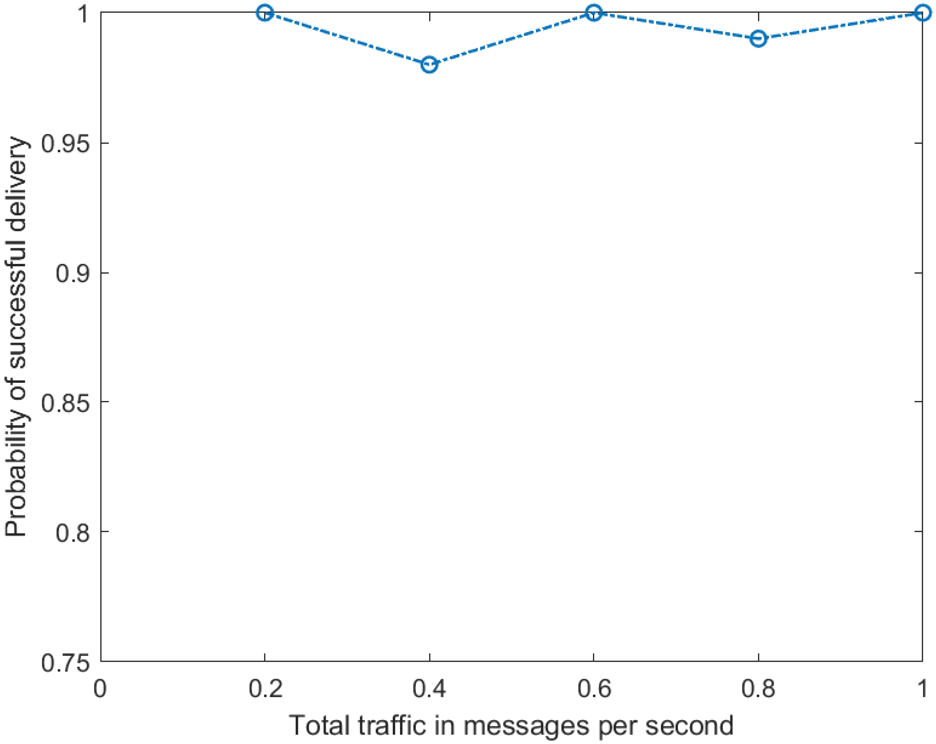
We have tested the system with two relays, and two tags. We varied the rate at which each tag generates messages from one every ten seconds to one every two seconds. A thousand messages were generated by each tag in each experiment. The time a relay waits before transmitting is exponentially distributed with mean delay of 100 ms. A Spreading Factor of 7 and bandwidth of 500 kHz were used in the LoRa physical layer giving a bit-rate of 21,875 bps. The results are shown in Figure 1. For this level of traffic the delivery success rate is very high.
4. Analysis
Although implementation and field trials gives us some confidence that the system will be effective, determining how scalable it is, is difficult with only a few nodes. Consequently, to explore the sizing of the system we turn to mathematical and simulation models.
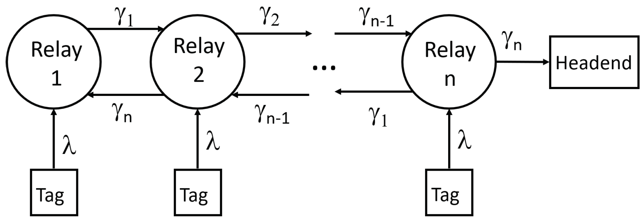
We can model this system using conventional Markov methods. Each relay receives messages from tags. We make the simplifying assumption that arrivals are uncorrelated and the time between them is exponentially distributed. Each relay, upon receipt of a message from a tag, in order to avoid collisions, waits a random amount of time before broadcasting the message to its neighbouring relays to forward. During this time the relay is unable to receive other messages. The time includes both the transmission time and an additional randomly distributed interval to reduce the risk of collisions with other messages. With these assumptions we can model the system as a Markov chain as shown in Figure 2.
The number of relays in the system is denoted by n. Each relay k receives messages from tags in its locality. We assume each tag generates messages with a mean rate of . The number of tags at each relay is . The aggregate traffic into relay k is . In this analysis we assume that the number of tags is the same for each relay and consequently, the rate at which messages enter each relay is also the same, which we denote by . We make the simplifying assumption that is exponentially distributed.
We denote the rate of traffic between relays k and by . We can determine the following recursive relationship defining the traffic leaving each relay:
where is the probability a relay forwards a message and .
Any traffic that is transmitted by either a neighbouring relay or a tag will be lost if the relay is currently transmitting or waiting to transmit. We can model this behaviour as an M/M/1/1 queue. In this queue the probability of blocking is:
where is the queue utilisation. Consequently, the probability of admission is:
We now need to determine . For an M/M/1/1 queue is:
The service rate is the inverse of the time spent randomly waiting after the medium goes silent plus the time taken to transmit the message which we denote by T giving a service rate . However, the arrival rate into each relay is much more difficult to determine. A consequence of using flooding is that traffic propagates both up and down the network meaning that relay k will have traffic entering it of and making the calculation of difficult. However, we can approximate . Although it will overstate it, we can approximate the traffic entering each relay by . Consequently, we can approximate by . Therefore an approximate value of is given by:
We expect this to overstate the value of and hence overstate the blocking probability and consequently understate the throughput of the network. Nevertheless for lightly loaded networks where the approximation should be reasonable. In the next section we demonstrate that this is true.
Using these simplifications we can determine an approximate value for the network throughput which is the traffic leaving the headend at relay n:
Finally we can determine the probability of successful delivery by dividing throughput by total offered traffic.
Figure 3 shows the predictions from the above model and from a simulation of the system. As expected there is good agreement between the analytical model and the simulation when the load on the network is light but, also as expected, the agreement is less pleasing as the load increases. Nevertheless, the agreement is sufficient to explore the scalability of the system.
5. Scalability
To explore the scalability of the system as the number of relays and tags increase we simulate the system. In the analysis in the previous section we assumed an aggregate rate of traffic into each relay from the tags of . With simulation we can explore more complex scenarios where the arrival rate into individual relays is not the same across the network. We use simulation to explore the performance of the network as the number of tags increases and for different distributions of tags. We also consider three distributions of tags throughout the network. First is where the number of tags at each relay is the same for all relays. This should approximately match our analysis in the previous section. Second is where the number of tags further from the headend is greater than those nearer, and third, the converse where the number of tags nearer the headend is greater than those further away.
Our simulator is written using Matlab as a message passing system. In the simulation each relay and tag behaves as described in pseudo-code in Section 3.1.
Each relay keeps track of the highest message number it has received from each tag. Any message it receives is broadcast provided the message number is greater than the highest recorded and provided the message TTL is greater than zero. Each relay only sees messages from its nearest neighbors. Upon receipt of a message the relay waits for the medium to go silent and then broadcasts its message after a random interval as described previously. The channel is assumed to be lossless. Given the very good transmission characteristics we have observed of LoRa underground this is a reasonable assumption but exploring more lossy channel models is an area of potential future research.
For the remainder of the paper we simulate messages being transmitted over LoRa relays configured to use Spreading Factor 7, bandwidth of 500 kHz and coding rate 1 giving a bit-rate of approximately 22 kbps. Messages generated by the tags are 30 bytes long and are generated once every 60 s.
5.1. Rate of Successful Delivery
We begin by examining the success rate of the network in delivering messages successfully to the headend. We plot this rate against number of relays for the cases where each relay receives messages from 1, 2, 3 and 4 tags each.
We can see the performance of the system in Figure 4. The system performs well when each relay is lightly loaded even when there is a large number of relays. With 20 relays and one tag per relay the probability of successful delivery is approximately 0.85. However, when the number of tags per relay increases there is a substantial reduction in successful delivery rate. With two tags per relay it is 0.76, for three it is 0.64 and for four it is less than 0.60. This indicates that a deployment consisting of large numbers of lightly loaded relays may perform better than smaller numbers of heavily loaded relays.
5.2. Skewed Tag Distribution
In this sub section we examine the effect of an uneven distribution of tags across the network. Table 1 has two columns the first of which is the distribution of tags and the second is the probability of successful messsage delivery. The distribution shows the number of tags located each hop from the headend. All distributions include 16 tags. The first row shows a highly skewed distribution with all 16 tags located one hop from the headend. The second row shows eight tags located one hop from the headend and the remaining eight located two hops from the headend and so on.
The skewedness of the distribution appears to have only a small effect but we note the further from the headend the lower the delivery success probability. This is an important point because in an emergency, more resources are likely to be located furthest from the headend. Nevertheless, the effect is small. Where all 16 tags are located furthest from the headend the probability of successful delivery is 0.924 compared with 0.974 where all the tags are just one hop from the headend.
5.3. Fairness
The overall success rate of delivery gives us an incomplete view of the performance of the system. Traffic generated by tags many hops from the headend have a greater probability of being dropped than those nearer. We see from Figure 5 that the effect is most pronounced in networks with larger numbers of tags per relay. Where there is one tag per relay traffic generated ten hops distance has delivery success probability of 0.9 but for four tags per relay it is 0.65. Interestingly the probability of delivery success for messages generated closest to the headend is much less affected by the number of tags per relay than for messages generated at more distant relays. For tags one hop from the headend the delivery success probability is 0.98 for one tag per relay and 0.95 for four tags per relay. In contrast, for relays 10 hops distant the respective values are 0.90 and 0.65 respectively.
6. Conclusions
In this paper we have introduced a linear network based system we have developed for the transmission of location data in underground mines. The purpose of the system is to transmit low bit-rate data, primarily location data generated by tags carried by personnel and equipment, to a headend. The system is used during emergencies or when the main network has failed.
We have used the LoRa physical layer as the transmission technology and developed a protocol for message transmission. The protocol incorporates three key design decisions: flooding for message forwarding, sequence numbers and time-to-live fields for managing broadcast storms, and a simplified CSMA scheme for managing contention.
We have implemented and trialed a small version of the system which has given promising results. However, to explore the scalability of the system without having to deploy a large amount of hardware we have developed analytical and simulation models of the system. These have given us an indication of the nunber of tags and relays that can be expected to be able to be supported. We have found that large numbers of lightly loaded relays performs better than smaller numbers of heavily loaded relays. This may have some consequences for how the system is installed with larger numbers of low powered relays and tags preferred to smaller numbers of higher powered relays and tags.
Future work includes incorporation of location devices into the system, optimization of CSMA mechanism and larger trials involving the testing underground of larger numbers of nodes and tags.
Location data underground can be based on received signal strength and accelerometer data. Incorporating this into the system is an important step. However, there are issues to be explored relating to determining the location of the relays. As relays are put in place accelerometer data carried by the installers can give an indication as to the location of the relay. How accurate might that data be? There is the optimization of the delay in the CSMA scheme to be addressed. What is the optimal delay that maximizes throughput? We also plan to conduct larger underground trials.
Safety underground is a matter of profound concern to the mining industry. LoRa used in an emergency location system can help add to that safety.
Author Contributions
All authors contributed equally to this paper. All authors have read and agreed to the published version of the manuscript.
Funding
This research received no external funding.
Conflicts of Interest
The authors declare no conflict of interest.
References
- Branch, P.; Cricenti, T. A LoRa Relay Based System for Detonating Explosives in Underground Mines. In Proceedings of the 2020 IEEE International Conference on Industrial Technology (ICIT), Buenos Aires, Argentina, 26–28 February 2020; pp. 259–264. [Google Scholar]
- Wang, H.; Fapojuwo, A.O. A Survey of Enabling Technologies of Low Power and Long Range Machine-to-Machine Communications. IEEE Commun. Surv. Tutor. 2017, 19, 2621–2639. [Google Scholar] [CrossRef]
- Chen, G.Z.; Meng, Q.C.; Zhang, L. Chain-type wireless sensor network node scheduling strategy. J. Syst. Eng. Electron. 2014, 25, 203–210. [Google Scholar] [CrossRef]
- Hakem, N.; Delisle, G.; Coulibaly, Y. Radio-Wave Propagation into an Underground Mine environment at 2.4 GHz, 5.8 GHz and 60 GHz. In Proceedings of the 8th European Conference on Antennas and Propagation (EuCAP 2014), The Hague, The Netherlands, 6–11 April 2014. [Google Scholar] [CrossRef]
- Forooshani, A.E.; Bashir, S.; Michelson, D.G.; Noghanian, S. A Survey of Wireless Communications and Propagation Modeling in Underground Mines. IEEE Commun. Surv. Tutor. 2013, 15, 1524–1545. [Google Scholar] [CrossRef]
- Kunsei, H.; Bialkowski, K.S.; Alam, M.S.; Abbosh, A.M. Improved Communications in Underground Mines Using Reconfigurable Antennas. IEEE Trans. Antennas Propag. 2018, 66. [Google Scholar] [CrossRef]
- Zhou, C.; Plass, T.; Jacksha, R.; Waynert, J.A. RF Propagation in Mines and Tunnels: Extensive measurements for vertically, horizontally, and cross-polarized signals in mines and tunnels. IEEE Antennas Propag. Mag. 2015, 57, 88–102. [Google Scholar] [CrossRef]
- Rizos, C.; Li, B.; Zhao, K.; Saydam, S.; Wang, Q. Third generation positioning system for underground mine environments: An update on progress. In Proceedings of the IGNSS Symposium, Sydney, Australia, 6–8 December 2016. [Google Scholar]
- Yarkan, S.; Guzelgoz, S.; Arslan, H.; Murphy, R.R. Underground Mine Communications: A Survey. IEEE Commun. Surv. Tutor. 2009, 11, 125–142. [Google Scholar] [CrossRef]
- Zhohov, R.; Minovski, D.; Johansson, P.; Andersson, K. Real-time Performance Evaluation of LTE for IIoT. In Proceedings of the IEEE 43rd Conference on Local Computer Networks (LCN), Chicago, IL, USA, 1–4 October 2018. [Google Scholar]
- Liao, C.H.; Zhu, G.; Kuwabara, D.; Suzuki, M.; Morikawa, H. Multi-Hop LoRa Networks Enabled by Concurrent Transmission. IEEE Access 2017, 5, 21430–21446. [Google Scholar] [CrossRef]
- Lundell, D.; Hedberg, A.; Nyberg, C.; Fitzgerald, E. A Routing Protocol for LoRa Mesh Networks. In Proceedings of the 2018 IEEE 19th International Symposium on “A World of Wireless, Mobile and Multimedia Networks” (WoWMoM), Chania, Greece, 12–15 June 2018; pp. 14–19. [Google Scholar] [CrossRef] [Green Version]
- Abrardo, A.; Pozzebon, A. A Multi-Hop LoRa Linear Sensor Network for the Monitoring of Underground Environments: The Case of the Medieval Aqueducts in Siena, Italy. Sensors 2019, 19, 402. [Google Scholar] [CrossRef] [Green Version]
- Lee, H.C.; Ke, K.H. Monitoring of Large-Area IoT Sensors Using a LoRa Wireless Mesh Network System: Design and Evaluation. IEEE Trans. Instrum. Meas. 2018, 67, 2177–2187. [Google Scholar] [CrossRef]
- Branch, P.; Cricenti, T. A LoRa Based Wireless Relay Network for Actuator Data. In Proceedings of the 2020 International Conference on Information Networking (ICOIN), Barcelona, Spain, 7–10 January 2020; pp. 190–195. [Google Scholar]
Figure 1.
Field Trials Probability of Successful Delivery.

Figure 2.
Markov chain model of system.

Figure 3.
Comparison of analytical and simulation models. Each tag generates one 30 Byte message every 60 s. Each relay forwards messages at service rate per second.
Figure 3.
Comparison of analytical and simulation models. Each tag generates one 30 Byte message every 60 s. Each relay forwards messages at service rate per second.

Figure 4.
Probability of successful delivery, one 30 Byte message every 60 s, service rate per second.
Figure 4.
Probability of successful delivery, one 30 Byte message every 60 s, service rate per second.

Figure 5.
Throughput, .


Table 1.
Probability of successful delivery with skewed tag distributions.
| Tag Distribution | Success Probability |
|---|---|
| 16 0 0 0 0 0 0 0 | 0.974 |
| 8 8 0 0 0 0 0 0 | 0.966 |
| 4 4 4 4 0 0 0 0 | 0.948 |
| 2 2 2 2 2 2 2 2 | 0.924 |
| 0 0 0 0 4 4 4 4 | 0.923 |
| 0 0 0 0 0 0 8 8 | 0.920 |
| 0 0 0 0 0 0 0 16 | 0.924 |
© 2020 by the authors. Licensee MDPI, Basel, Switzerland. This article is an open access article distributed under the terms and conditions of the Creative Commons Attribution (CC BY) license (http://creativecommons.org/licenses/by/4.0/).
Share and Cite
MDPI and ACS Style
Branch, P.; Li, B.; Zhao, K. A LoRa-Based Linear Sensor Network for Location Data in Underground Mining. Telecom 2020, 1, 68-79. https://0-doi-org.brum.beds.ac.uk/10.3390/telecom1020006
AMA Style
Branch P, Li B, Zhao K. A LoRa-Based Linear Sensor Network for Location Data in Underground Mining. Telecom. 2020; 1(2):68-79. https://0-doi-org.brum.beds.ac.uk/10.3390/telecom1020006
Chicago/Turabian StyleBranch, Philip, Binghao Li, and Kai Zhao. 2020. "A LoRa-Based Linear Sensor Network for Location Data in Underground Mining" Telecom 1, no. 2: 68-79. https://0-doi-org.brum.beds.ac.uk/10.3390/telecom1020006