Hybrid Multi-Antenna Techniques for V2X Communications—Prototyping and Experimentation


1
Department of Digital Systems, School of Information and Communication Technologies, University of Piraeus, 18534 Piraeus, Greece
2
General Department, National and Kapodistrian University of Athens, Thesi skliro, Psahna, 34400 Evia, Greece
*
Author to whom correspondence should be addressed.
Telecom 2020, 1(2), 80-95; https://0-doi-org.brum.beds.ac.uk/10.3390/telecom1020007
Submission received: 18 May 2020
/
Revised: 12 June 2020
/
Accepted: 29 June 2020
/
Published: 7 July 2020
(This article belongs to the Special Issue Vehicular Communications)
Abstract
:The support of the connected vehicle-to-everything (V2X) vision in conjunction with intelligent transportation system applications and services constitute a major 5G objective for modern radio systems and networks. More particularly, 5G deployment will involve multiple radio access network (RAN) technologies and a massive machine-type communication environment, offering a simultaneously supported variety of broadcast, multicast, and unicast applications. In this article, we present an implementation of a diversity engine able to support the multi-objective, multi-RAN, multi-service V2X use cases. The engine is enhanced with the adoption of a hybrid diversity scheme that exploits the beamshaping capabilities of the reconfigurable electronically switched parasitic array radiator (ESPAR) antennas. The hybrid scheme combines conventional maximal ratio combining with beamspace diversity and it improves system performance in terms of reliability and throughput with increased signal-to-noise ratio. It was implemented and demonstrated with integration of novel printed antennas on connected, vehicle-to-vehicle (V2V)-enabled trucks in the context of the Horizon 2020 project ROADART.
1. Introduction
Vehicle-to-everything (V2X) communications have gained a significant momentum globally, as the main enabler of intelligent transportation systems (ITSs) [1]. The latter one includes novel applications, services and technologies that aim to improve transport safety and efficiency, driver/passenger experience, and environmental performance, leading towards connected vehicles and autonomous driving [2,3]. The automotive sector is considered probably the most important vertical domain for 5G and beyond 5G communication networks, with both telecom and automotive industries competing for the exploitation of the new opportunities [4]. In this concept, a fundamental novel approach is the support of the dynamically varying heterogeneous network structures and topologies. In particular, the mechanism of direct mobile-to-mobile communications is inherently integrated in 5G [5]. Moreover, the 5G framework supports multiple radio access technologies enabling V2X communications—from existing (ITS-G5 [6]) and new evolving technologies (LTE-V2X in LTE Rel. 14 [7]) to an upcoming standard (eV2X)—yet to be defined, which will be included in future new radio (NR) releases [8].
5G defines three basic objectives [9]: (a) increased throughput via enhanced broadband, (b) massive machine-type communications (10x-100x more devices), and (c) ultra-reliable, low-latency communications. The first 5G release focuses on objective (a), while the second on (b). On the other hand, V2X and ITS impose significant requirements on (b) and (c), while self-driving cars stand in the conjunction of all objectives. This means that V2X will have a central role in the formation and evolution of 5G. Thus, a new flexible architecture that increases throughput and reliability, while it decreases bit error rate (BER) and latency, is going to be the new communication paradigm towards 5G. However, such an architecture should always satisfy the stringent constraints that exist in V2X communication environments regarding the low latency and reduced complexity.
The performance of V2X, as well as other systems that support direct and/or adhoc communication modes can be further improved with the application of sophisticated transmission/reception techniques, which have already been used in legacy cellular systems. However, the direct adaptation of techniques in adhoc or partially controlled networks -like V2X- with fast-varying topologies and heterogeneous applications and services is not possible. In this context, one of the most efficient technique for system performance improvement is diversity. The term diversity refers to a set of multi-antenna transmission/reception schemes used to improve the quality and reliability of a wireless link. While transmit diversity with the use of space-time/frequency codes is already scheduled for integration in V2X, the direct application of receive or closed-loop transmit diversity methods is not a straightforward task due to various constraints inherent in V2X communications, for example, adhoc establishment and resolution of links, support of various modes of services simultaneously (broadcast, multicast, unicast), small dimensions and limited space for antenna and radio frequency (RF) equipment, low complexity requirements, and limited signal processing capabilities. The situation worsens in V2X channels, where the dynamic channel decreases the diversity gain due to outdated channel state information and the Doppler shifts. In addition, the current standard versions do not implicitly support diversity in transmitter (Tx) or receiver (Rx), thus, the system designer should apply diversity on-top of the system standardized operation.
In the context of low complexity multi-channels techniques for direct type of communications, various approaches have been proposed, for example, References [10,11,12,13,14,15,16]. For example, in Reference [13], a new compact antenna module suitable for combined use with LTE and ITS-G5 was proposed and its performance was evaluated through simulation. Nevertheless, the integration of multiple antennas in real-world mobile radio transceivers imposes significant challenges rising from the variety of hardware and signal processing constraints as well as the peculiarities of the wireless medium. In this article, we present a novel hybrid diversity scheme that simultaneously supports multi-mode services, and has been developed and tested under real-world conditions in the context of H2020-ROADART project. The scheme exploits the capabilities of electronically switched parasitic array radiator (ESPAR) antennas, which demonstrate considerably reduced complexity and size, compared to conventional multi-antenna solutions. Capitalizing on the additional degrees of freedom offered by the ESPAR antennas, the design of a new diversity engine is presented. The engine implements a flexible, hybrid scheme that combines conventional diversity, that is, a maximal ratio combiner (MRC) and a pattern selection technique built on low-cost, compact ESPAR antennas. Finally, the new technique was integrated in a real-world testbed for truck-to-truck (T2T) communications and the results from various experimentation trials are presented. It is noteworthy that the new diversity engine is compatible with all current V2X technologies (NR, LTE or WiFi-based solutions) and new features can be easily integrated on it as new standards and technologies emerge.
The paper is organized as follows. In Section 2, the basic principles of the ESPAR antennas, the diversity concept as well as the main steps that were followed for their configuration are presented. Moreover, in Section 3, a detailed description for the hybrid diversity engine is presented, in which the operational algorithm and the reconfiguration procedure are analyzed. In Section 4, various performance results are given, based on a real world vehicle-to-vehicle (V2V) communication testbed that has been built. Finally, in Section 5, the concluding remarks are provided.
2. Distributed Multiple Antennas for V2X Communications
2.1. ESPAR Antennas
There are plenty of multiple-input multiple-output (MIMO) techniques, that is, spatial multiplexing, diversity, and beam forming, that have been introduced in order to deal with the numerous V2X challenges and accomplish a satisfying V2X link performance. However, most of the antenna designs that have been used in the recent ITS systems can be considered as conventional antenna models with a single radiating element, that is, wire/printed monopole or PIFA, usually located in the side mirror or the vehicle’s roof [17,18]. These antenna designs do not endorse any digital techniques since they offer a fixed radiation pattern. Moreover, certain antenna array examples (or multiple antenna systems) have been developed for vehicles. Nevertheless, these antenna arrays demonstrate large dimensions, high complexity, high cost and various other drawbacks [19,20,21]. The same disadvantages are also encountered in a few proposed MIMO antenna systems that are integrated in a shark-fin structure [22,23,24].
A reconfigurable antenna can be considered as an ideal candidate to substitute a multiple-antenna system and satisfy the cost and space limitations that are established by vehicle and truck manufacturers for V2X communication antennas. The ESPAR antennas constitute a special category of reconfigurable antennas that offer the feature of pattern reconfigurability by electronically adjusting the loads of the parasitic elements [25,26]. Specifically, the ESPAR antennas are formed of a single active element and a specific number of parasitic elements that are distributed close to the active according to a certain geometrical arrangement (linear, circular etc.). The parasitic elements are located in a closer distance compared to the conventional antenna arrays and thus, they offer a smaller size, providing a relatively compact size to the final antenna system.
Moreover, ESPAR antennas provide a reduced complexity and low fabrication expenses since they involve a single active element and a single RF chain. However, the main advantage of the ESPAR antennas is the ability to control their radiation pattern. In detail, the close proximity between the active and the parasitic elements generate significant mutual coupling effects and induce strong currents flowing on the parasitics that influence the total radiation pattern of the array. Therefore, by controlling the impedances of the parasitic elements either with RF switches (PIN diodes) or variable capacitances (varactors), it is fairly simple to adjust the mutual coupling and reconfigure the radiation pattern of the array. Pattern reconfigurability provides to the ESPAR antenna the capability to employ diversity, MIMO, and beam-forming techniques [27]. The superiority of the ESPAR antenna compared to a single monopole radiator for a V2X communication link is also demonstrated in Reference [28]. Simulation results using the IST-WINNER channel model for T2T links are presented, that verify the suitability of the 3-element ESPAR for the specific application.
2.2. Configuration of the ESPAR Antenna and Performance
According to the investigations of References [29,30], the upper plastic arm of the truck side mirror is selected as the optimum location for the antenna’s installation. The first ESPAR antenna design attempt is carried out by employing conventional wire monopoles as the array elements. The proposed 5-wire monopole ESPAR antenna consists of one active and four parasitic elements in circular configuration, placed on top of a ground plane. Minimum radiation tilt is maintained with the use of a ground skirt. However, the size of the 5-element ESPAR antenna is relatively large compared to the limited available space of the upper mirror arm and an alternative, more compact solution should be followed.
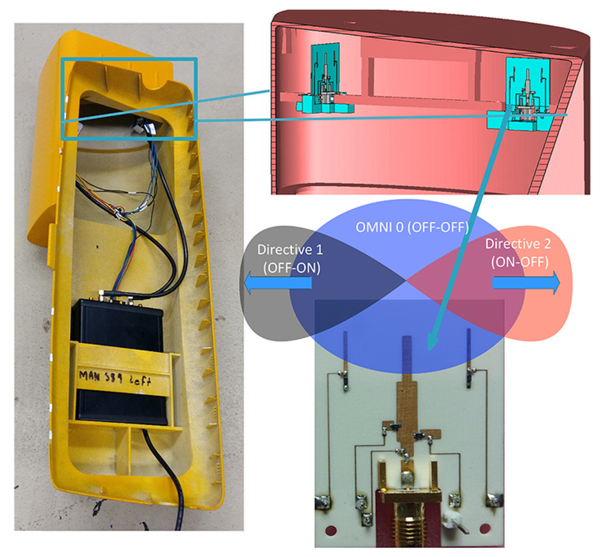
The second ESPAR antenna that is developed is 3-element printed ESPAR. The proposed ESPAR antenna is implemented in a planar structure and it was designed using an electromagnetic solver (CST 3D) [31]. Particularly, it employs one active and two parasitic monopole elements printed on a dielectric substrate (antenna panel). The two parasitic elements are located at the opposite ends of the antenna panel in a close distance from the actives (/5), enabling this way the beamforming capability of the ESPAR. Two PIN diodes are utilized as electronic switches between the parasitic elements and the ground plane in order to create an L-shaped reflector and control the beam of the antenna. In that manner, the three different PIN diodes’ combinations (ON-OFF, OFF-ON, OFF-OFF) produce three different radiation patterns (two directive beams and one omni-directional pattern). Our antenna research team has great investigation experience on ESPAR antenna designs [28,30,32,33]. However, there are a couple of technical issues that have been observed in the aforementioned designs.
The first one is the observation of small deviations in the results of the antenna’s return loss () between the operating antenna modes (OFF-OFF, ON-OFF) [32]. This is solved, in the current ESPAR design, by employing a reconfigurable impedance matching network also integrated in the antenna panel. The impedance matching network is realized by adding two open microstrip stubs in the microstrip structure. The stubs are connected to the quarter wavelength microstrip transformer line by two PIN diodes, providing this way suitable matching for the three antenna operating states. The second disadvantage of that type of ESPAR antennas is the significant tilt of the radiation patterns (E-plane) that is caused by the ground plane of the monopole. This is again addressed in this design by expanding the “height” of the ground plane and introducing the ground skirt effect that minimizes the radiation tilt.
The fabrication of the ESPAR antenna was executed by photoetching and the components (SMA connector, PIN diodes, inductors, capacitor, DC pins) were soldered by hand. As far as the integration is concerned, two antennas were installed per side truck mirror of two trucks, which were proved to be optimal positions for V2V link performance for trucks, according to the outcomes of the antenna position investigations that our research team carried out in Reference [29]. The ESPAR antennas were positioned in a perpendicular arrangement in order to achieve better azimuthal coverage. Figure 1 shows the prototype of the 3-printed monopole ESPAR antenna along with the position of the two antennas inside the side mirror case.
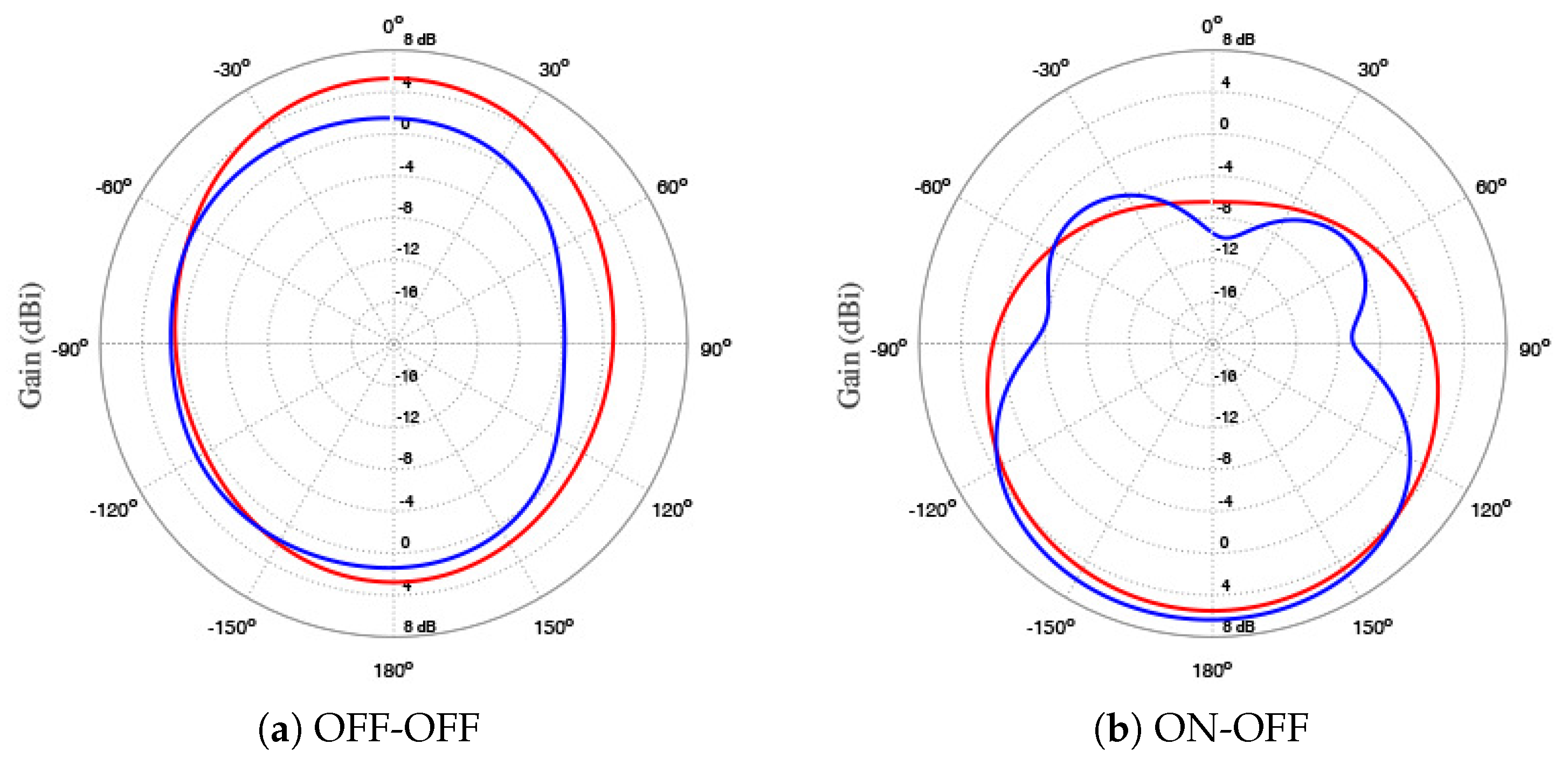
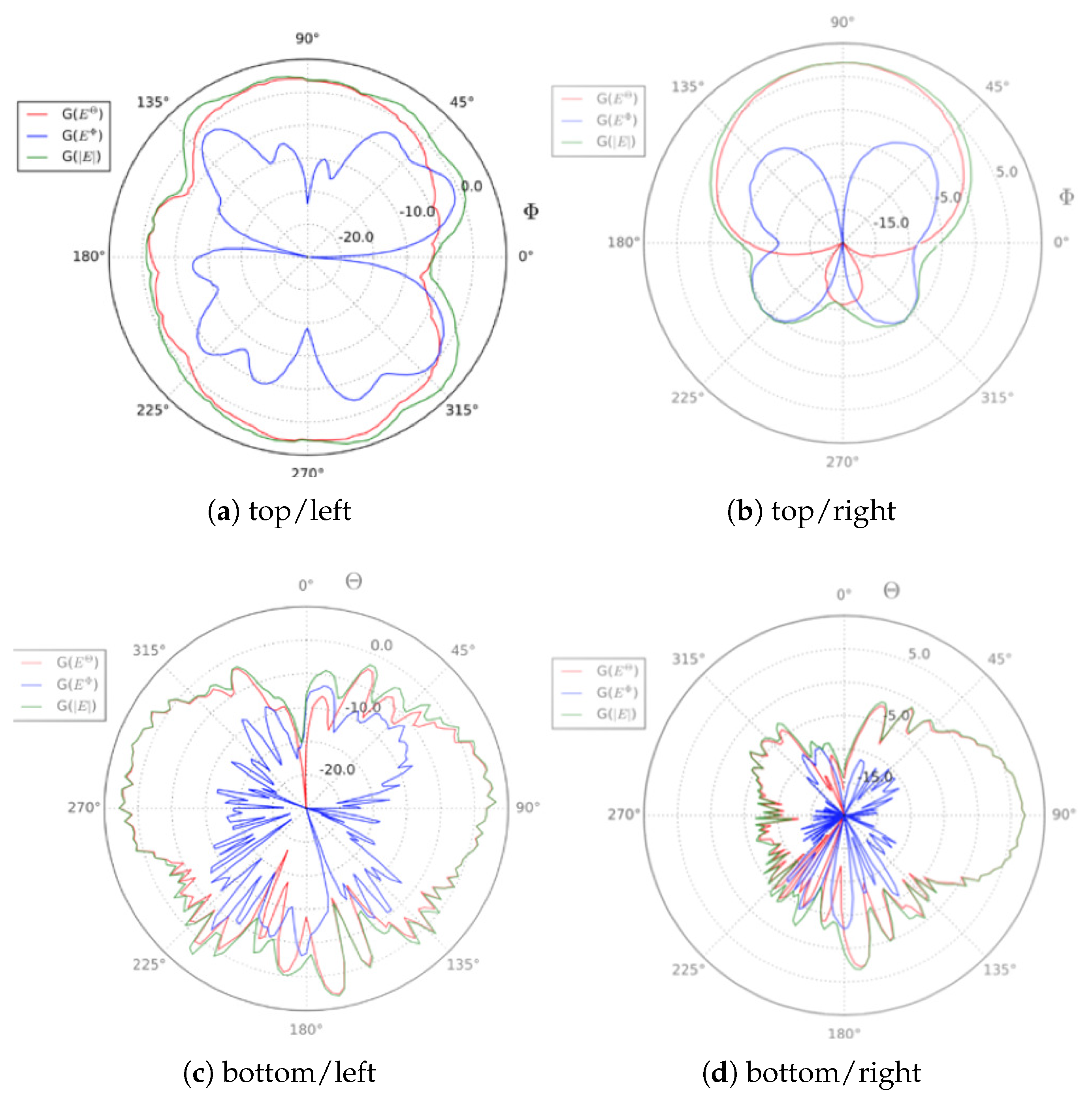
Figure 2 compares the simulated gain patterns in H-plane for both ESPAR antenna designs (5-wire monopole ESPAR and 3-printed monopole ESPAR) in red and blue colour respectively, for the omni-directional (Figure 2a) and the directive cases (Figure 2b). The planar structure of the printed ESPAR causes the non-perfectly (quasi) omnidirectional pattern (“squeezed shape”). The omni-directional radiation pattern of the 5-wire monopole ESPAR is more symmetrical. However, the integration of the 5-element ESPAR in the upper plastic mirror arm was considered to be impossible due to its large dimensions. Figure 3 depicts the four measured gain patterns of the 3-printed monopole antenna, omnidirectional (omni) and directive in left and right side respectively (in both H-plane/top and E-plane/bottom). A significant 3–4 dB gain increase is observed from the OFF-OFF to the ON-OFF antenna state.
2.3. Diversity Concept
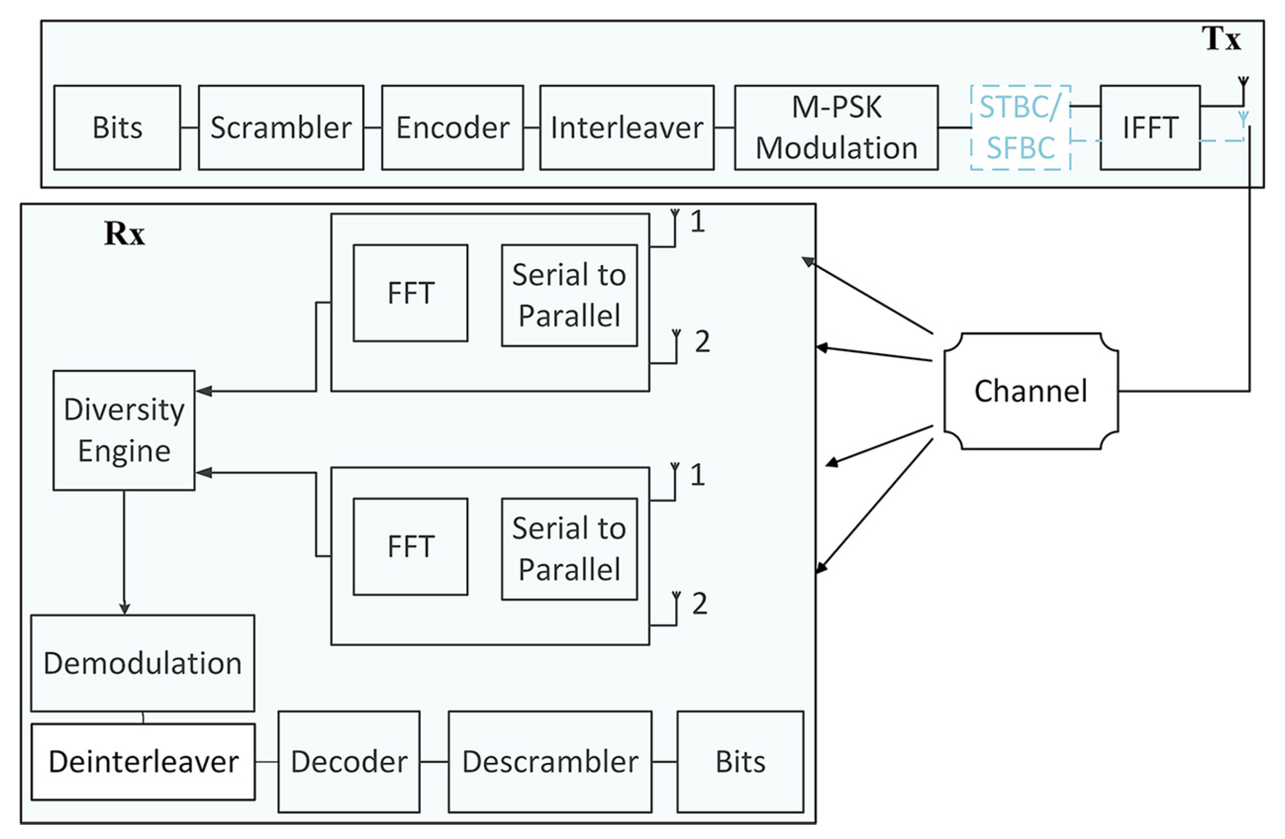
In Figure 4, a generic view of the block-diagram for an orthogonal frequency division multiplexing (OFDM)-based diversity communication system is presented. Such a transmission scheme is common for all recent V2X communication standards. The system can be divided into three main parts, the Tx, the Rx, and the channel. The basic blocks for the signal processing procedure at the Tx include: scrambling, encoding, modulation, and inverse fast Fourier transform (IFFT) implementation. The Tx employs a single-antenna, however, we have also included an optional space-time/frequency block encoder (STBC/SFBC) that enables Tx diversity (with the use of two antennas). It is noted that ITS-G5 does not support STBC or SFBC. The option is expected to be included in the future C-V2X versions, however, it was not included in the final version of the 3GPP Rel. 15 standard.
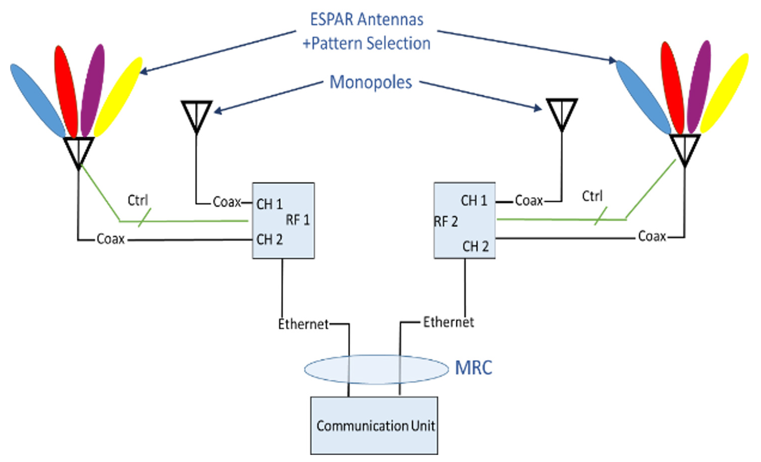
At the Rx, the diversity engine is located after the OFDM demodulator. The Rx also includes the complementary/inverse functions with respect to the Tx. Moreover, the main idea for the implementation of the diversity engine is depicted in Figure 5. Based on it, the Rx is composed by a set of RF modules and a communication unit. In our implementation the compact RF modules were also placed inside the truck mirrors—very close to the antenna. Each RF module contained two RF chains. The signal from the four RF chains is digitized and led to the communication unit, where the hybrid diversity scheme is applied in the baseband. According to the adopted concept, signal digitization is performed near the antennas, therefore, the cable length between the antennas and the communication unit does not introduce any extra attenuation. Thus, antennas can be mounted on the side mirrors (or any other place on the truck), while the communication unit resides into the vehicle with no signal quality degradation.
The proposed diversity scheme is an ideal candidate for vehicular communications, since:
- it provides increased MIMO support with a limited number of RF chains;
- it utilizes small, compact antennas able to be installed in many parts of the vehicle, which can improve links’ quality (with other vehicles or the infrastructure);
- it is designed to minimize the need for extra cabling, especially regarding the rigid and lossy RF cables—a significant requirement imposed by the auto-manufacturers;
- it provides significant diversity and beam-tracking gain on-top (and without modification) of the generally simplistic V2X protocols that do not yet explicitly support multi-antenna configurations;
- it allows the simultaneous improved support for both broadcast and unicast ITS services. The latter ones consist of a set of broadcast single message services, but also a set of peer-to-peer communication ones. Moreover, some types of future single message services (e.g., platooning) may benefit by beam steering/tracking optimizing transmission along the direction of the platoon movement.
3. Detailed Description of the Diversity Engine
Let’s consider two vehicles (A and B), which are equipped with the diversity engine depicted in Figure 6. At the base of the engine, an MRC is employed, which combines the received signal-to-noise ratio (SNR) from the four independent RF chains. In the course of the research activities, other diversity schemes were also tested, that is, equal gain combining (EGC), antenna selection and minimum mean square error (MMSE). The MRC was selected as the one with the best performance, despite the fact that MMSE is theoretically optimal in terms of SNR. However, the MMSE requires knowledge of the noise and interference variance, thus, for its real-world implementation a noise power estimator was also used. Due to the estimation error and the non stationary nature of the noise+interference level in dynamic vehicular environments, the MMSE diversity performance diverged from its expected optimal behavior.
Uncorrelated signal reception is desired in order to maximize the diversity gain and this is ensured due to the increased distance among the ESPARs. In order to evaluate the received SNRs, the engine uses measurements of the error vector magnitude (EVM) at the received quadrature phase-shift keying (QPSK) constellation of pilot symbols, in conjunction with the automatic gain controller (AGC) values for each RF chain. It is also assumed that the system hosts two sets of applications. The first set contains services and applications in broadcast mode of operation (i.e., reception of cooperative awareness messages), while the second set involves the direct communication of A and B, implementing, for example, a platoon. Thus, in the investigated scenario, the two transceivers host two services, a single message service and an A-to-B unicast.
In order to describe the simple but yet efficient operation of the diversity engine, an exemplary use case is presented where A and B are communicating directly with the use of a V2X standard (ITS-G5 or C-V2X/PC5). Initially, it is assumed that B receives an ITS packet. The received packet is processed and if originated by A, it is forwarded to the diversity engine, which uses the selected metrics (EVM and AGC values) in order to decide whether to change the currently selected combination of patterns of the four ESPAR antennas. All engine decisions are taken during reception. During the transmission phase, B employs the combination of patterns selected during the receiving phase. Due to the reciprocity principle, it is expected that the pattern that optimizes reception from A, also offers increased power towards A. The same operation is also followed by vehicle A. Since many unicast, multicast, and broadcast applications are required to operate in parallel, functionalities that ensure coexistence of omni and directive patterns were also developed, as demonstrated below.
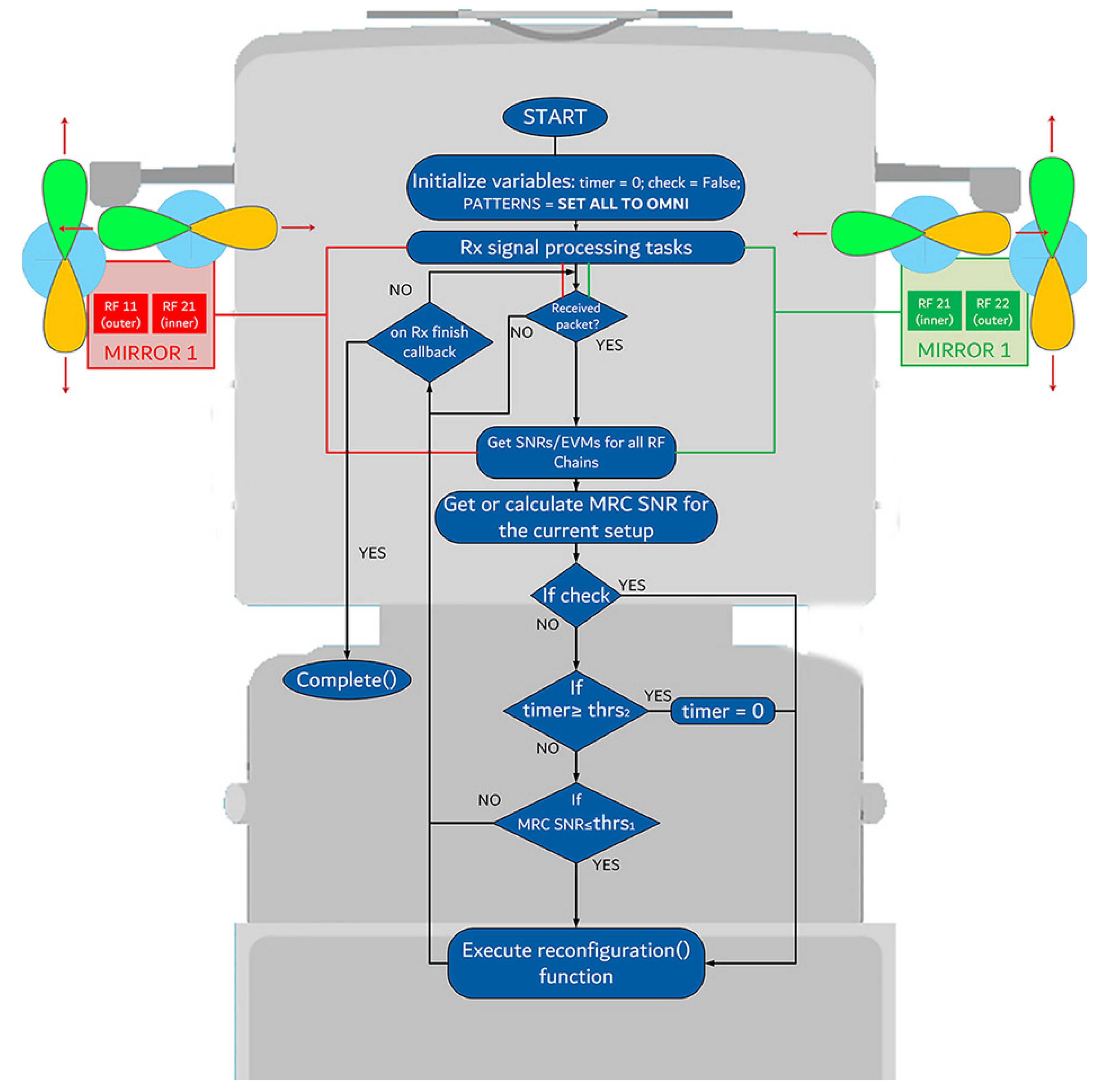
During the field trials of the ROADART project, the implemented diversity engine was able to support various modes of operation, including random selection of pattern combinations for each RF chain or user-defined manual pattern selection. Here, we focus on a simple, automated, standard-agnostic, and yet remarkably efficient approach presented in the flow graphs of Figure 6 and Figure 7. During the field trials, the 3-element ESPAR with PIN diodes were used—providing three active patters per antenna (the notation used is 0: omni, 1: front, 2: back). As shown in Figure 6, the basic operation of the diversity scheme depends on two thresholds ( and ) related with the two control parameters, that is, MRC SNR and a timer, respectively. Initially, all patterns are set to omni. The rationale of the diversity algorithm is the following:
- The pattern reconfiguration for the RF chains depends on the MRC output value; if it falls below a predefined threshold (), the reconfiguration procedure will initiate. Therefore, the pattern combination will not change if the SNR of the current selection does not fall below , despite the fact that a different combination with better performance may exist. In this context, continuous unnecessary changes are avoided, which results to a complexity reduction and avoidance of synchronization problems. At the same time, important performance degradation is avoided, since the use of ensures that the MRC-SNR remains relatively high.
- When on transmit-mode, the transceiver will select either the omni pattern for single message broadcast, or the pattern combination that was decided during reception in order to optimize the link between B and A.
- On the other hand, if reconfigurations have not been performed for more than received packets (parameter timer of Figure 6, the diversity engine will attempt to reconfigure and search for a better pattern combination, despite the fact that the SNR threshold is not violated. The reconfiguration trigger through the timer is used in order to periodically force the system to search for better pattern combinations and improve performance, even if the SNR remains relatively high.
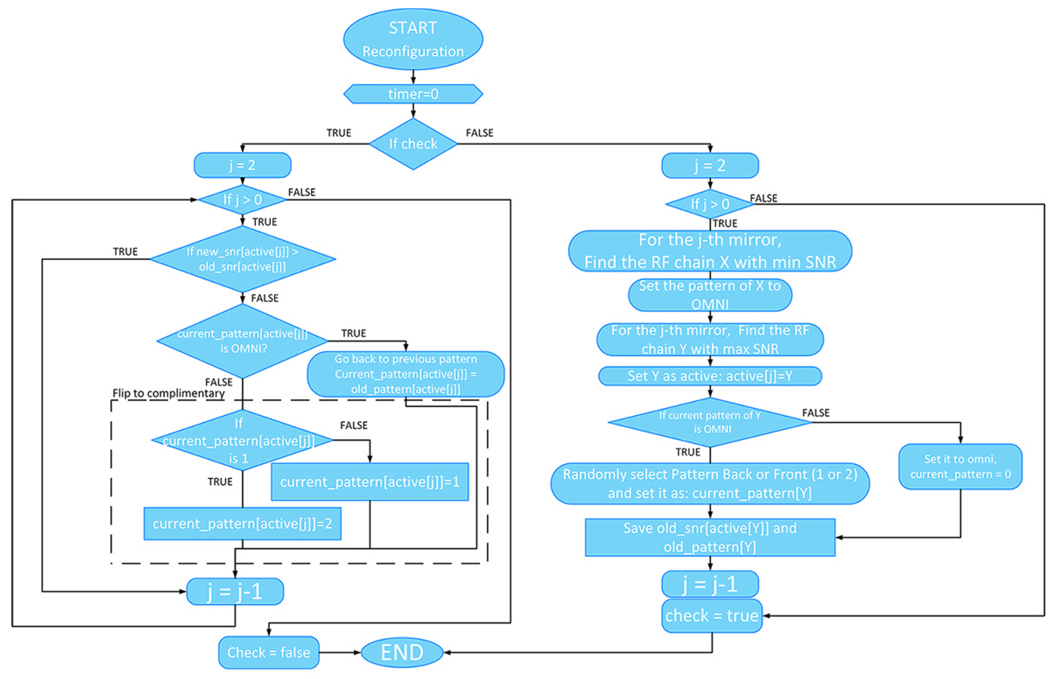
The reconfiguration procedure is presented in Figure 7. It is performed in two stages, since there is no explicit channel state feedback mechanism defined in the standards. During the first stage (variable check = false in Figure 6 and Figure 7), for each pair of antennas, that is, each side mirror in our implementation (defined by counter j), the engine estimates the received SNR. The main reconfiguration rule is that for each j, the RF chain with the minimum SNR is set to omni and the one with the maximum SNR is selected for reconfiguration and is denoted as “active-directive”. This policy will allow us to exploit maximally the directive gain of the “active-directive” antenna, while we maintain the use of an omni antenna for the exchange of broadcast messages through all directions.
For the case of the “active-directive” antenna, the first reconfiguration step is defined as follows: If the current pattern is directive (pattern 1 or 2), then the omni pattern, 0, is selected. Otherwise, directional patterns are selected in a random manner. The status of the previous pattern combination is saved and the same procedure is performed for the other pair of antennas (or all j’s existing in the system).
At the second stage (check = true), the selected pattern for the active RF chain of each antenna pair is evaluated and the system validates the reconfiguration procedure as successful or failed. If the measured SNR is increased compared to the previous formation, then the reconfiguration is assessed as successful. On the other hand, if the estimated SNR is decreased, the reconfiguration attempt is considered failed and two scenarios exist depending on the formation of the current pattern: if it is omni, then the previous selected pattern is restored, since it is assessed as the optimum for the current radio channel state and despite the fact that reconfiguration was triggered, no SNR improvement can be achieved; if it is directive, the opposite directive pattern is selected, since the current selection does not favor propagation towards the desired direction. In any case, at least two antennas are set to omni. This is necessary for the rapidly varying vehicular network, since the vehicle should be able to receive/transmit beacon and traffic messages from/to all directions as part of the safety-related, single message services of the ITS framework.
A far as the integration phase is concerned, the diversity engine was implemented as a software module in C++ and executed on the communication unit that is digitally connected to the RF modules, as shown in Figure 6. Moreover, just like the RF modules, Linux operating system was also uploaded on the communication unit. The communication unit software is hosted on a Linux operating system.
4. Performance Evaluation, Field Tests, and Results
The performance of the diversity engine has been evaluated in field measurements using various key performance indicators (KPIs). The engine collects, measures, and/or calculates the following KPIs:
- Output SNR;
- SNR diversity gain, as compared to a single-input-single output omni (SISO-OMNI);
- Bit error rate (BER);
- Packet error rate (PER);
- Coverage probability;
- Channel capacity/Achievable throughput;
- Latency.
The field tests were performed in the context of the H2020-ROADART project, with the integration of a real-world T2T communication testbed. The measurements were conducted in a test truck (from MAN Trucks and Busses) as well as in public highways. Tests involved two trucks moving as a convoy for various inter-vehicle distances.
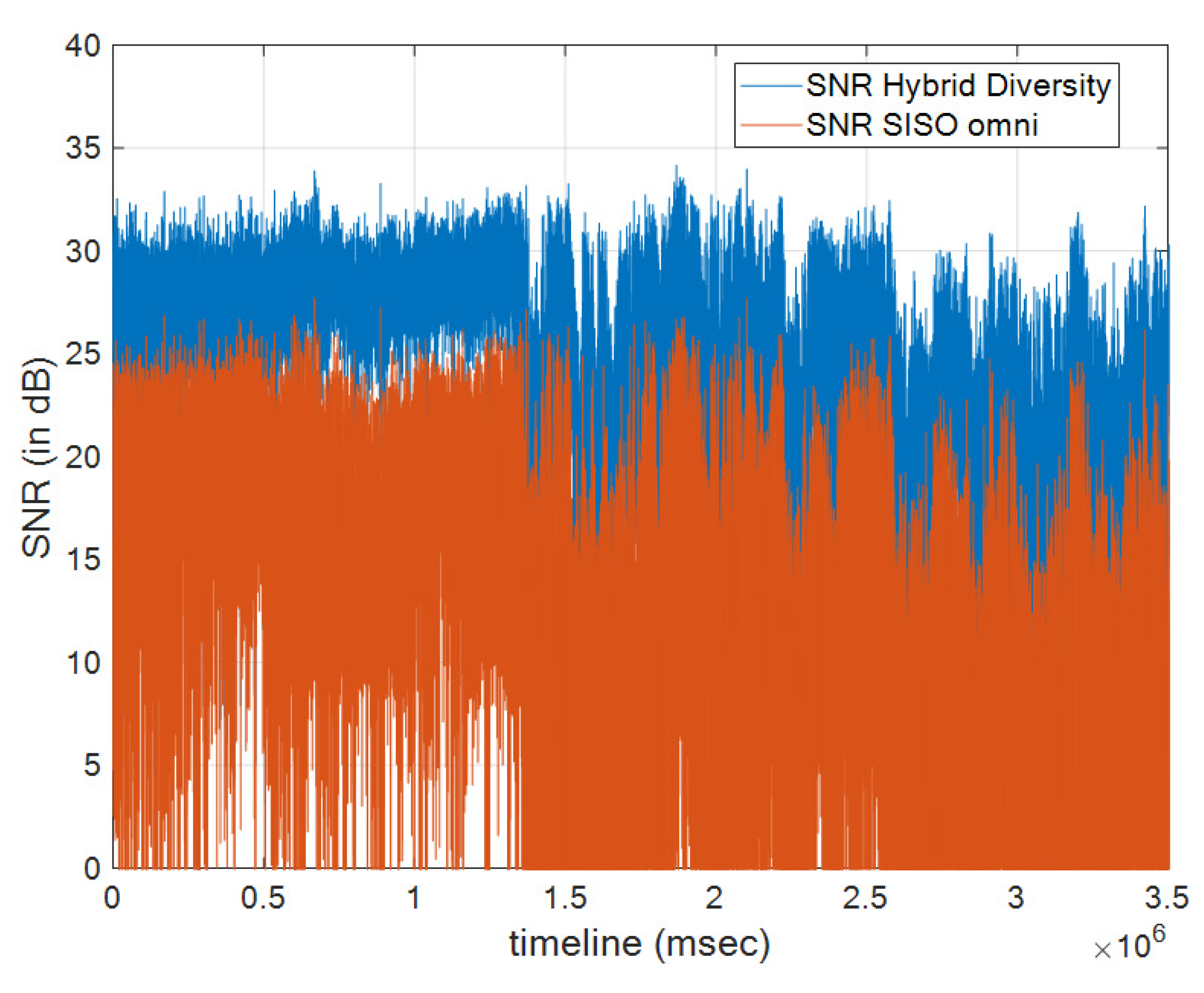
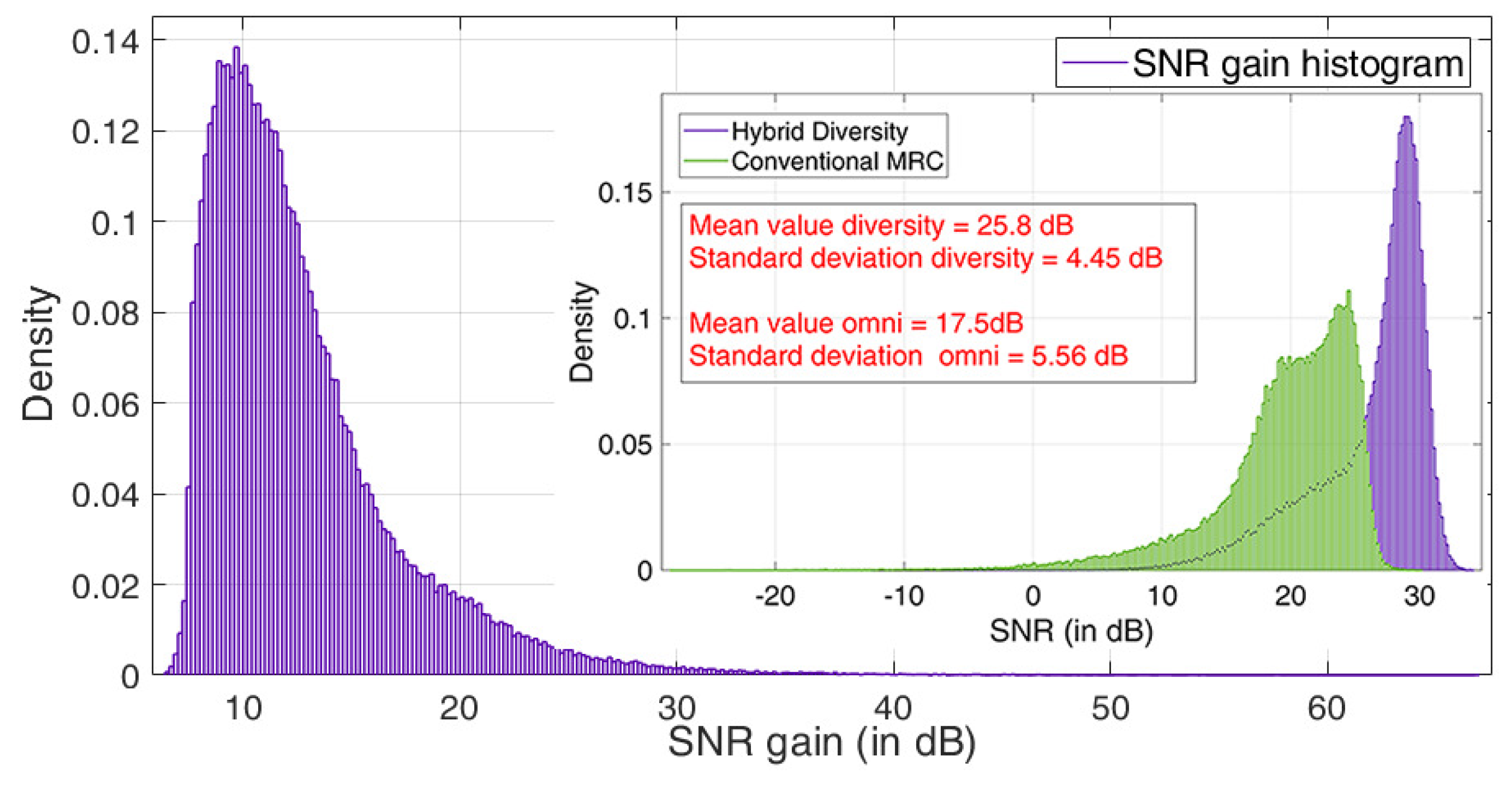
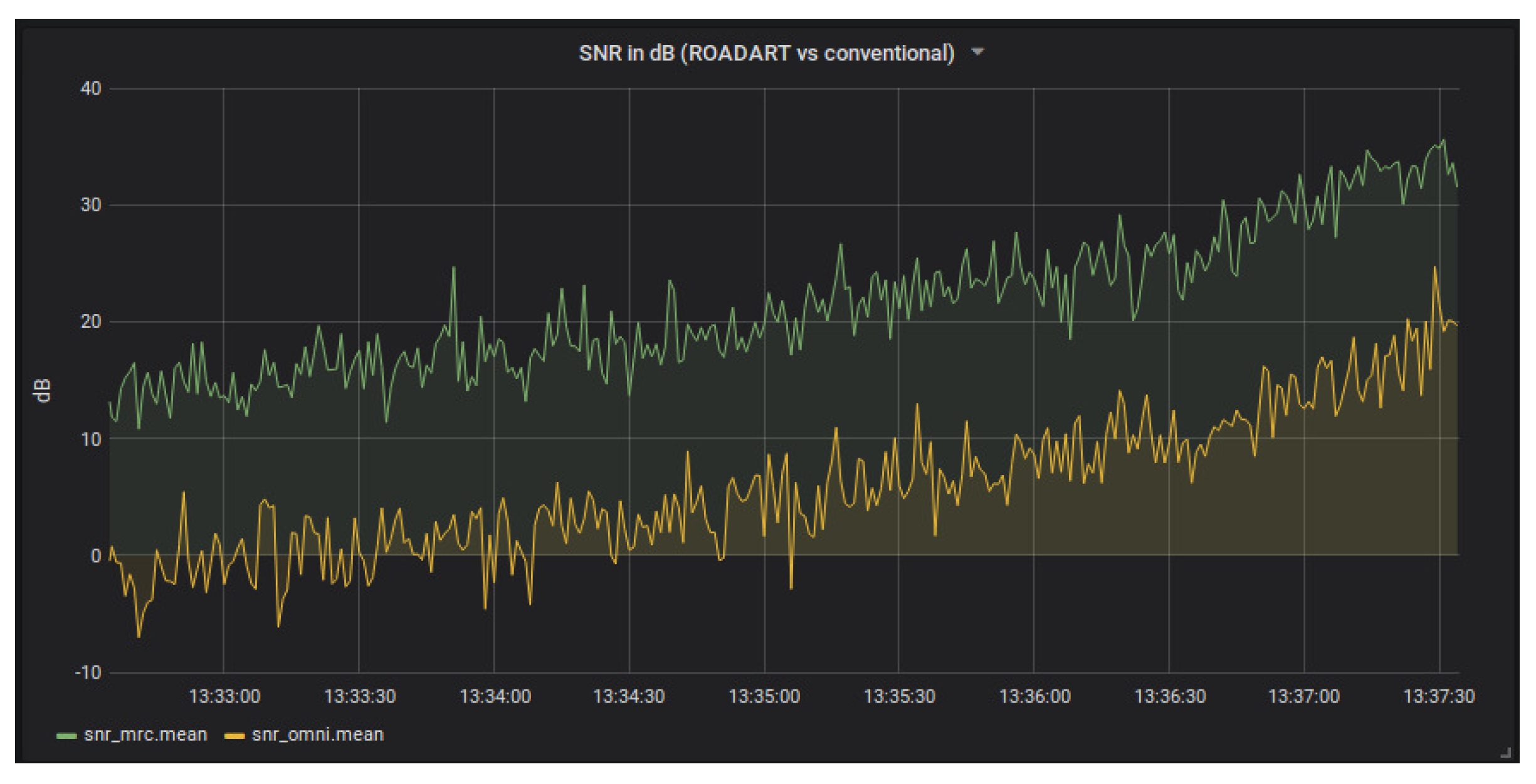
Next, a few representative performance results, which have been obtained using the data gathered during these tests, are presented and discussed. In Figure 8, a plot of the time variation of SNR values as the two trucks were driving along the test highway route is presented. The superiority of the implemented diversity engine is clearly depicted as compared to a SISO omni system. Moreover, in Figure 9, the empirical probability density function (PDF) is shown for the diversity gain of the proposed hybrid diversity scheme as compared to SISO-OMNI. From this plot, it is observed that the diversity gain is 12 dB on average. In the same figure, the empirical PDF of the received SNRs for the proposed hybrid scheme vs. one employing conventional MRC diversity reception, that is, without ESPAR antennas and pattern selection, is also presented. It is shown that the reconfigurability of the antennas considerably improves the output SNR and thus the overall system’s performance.
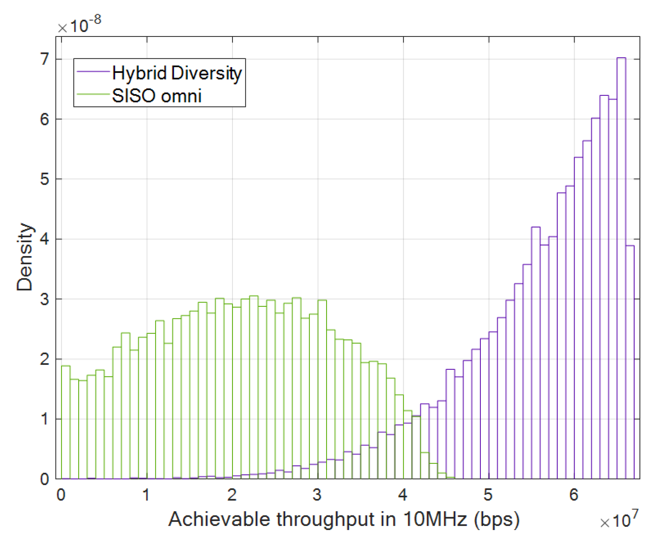
In Figure 10, the empirical PDFs of the achievable throughput for the hybrid diversity vs. SISO-OMNI schemes are plotted, assuming 10 MHz signal bandwidth at 5.9 GHz. It is observed that the diversity engine increases by 2.5 times the channel capacity confirming the performance improvement achieved by the proposed scheme.
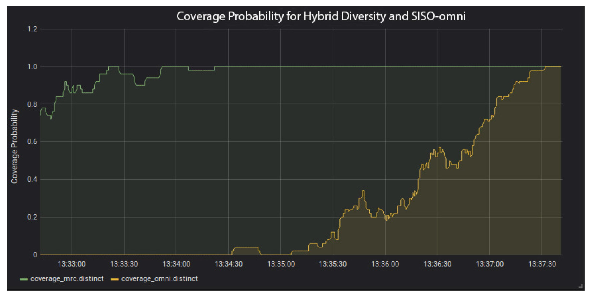
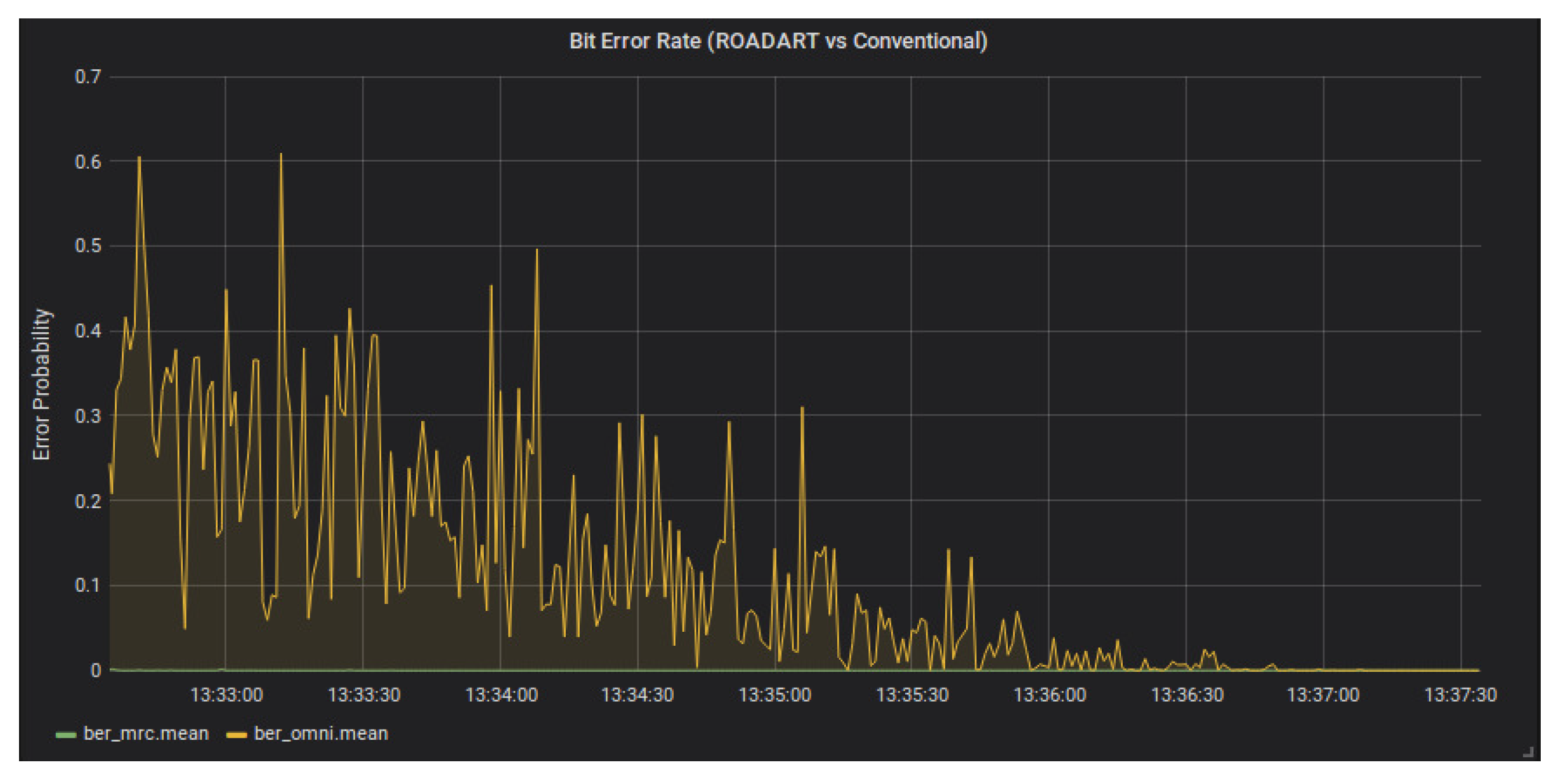
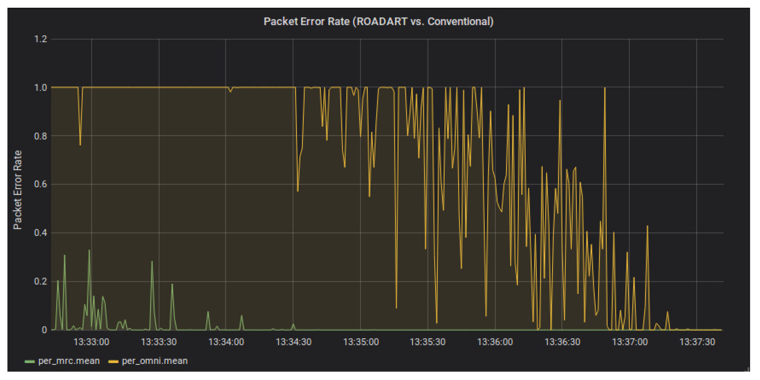
Figure 11, Figure 12, Figure 13, Figure 14 and Figure 15 depict screenshots from the conducted real-world experiments, as captured from the Grafana visualization tool that was used for real-time system monitoring and demonstration during the trials. In the specific set of experiments, inter-vehicle distance was initially quite large (more than 1 km) and it was gradually reduced. At the end of the experiments, the inter-vehicle distance was below 50 m. Figure 11 represents the significant SNR gain offered by the use of the diversity engine compared with the SISO-OMNI system. Consequently, the following figures present the comparison of the aforementioned KPIs. Figure 12 presents the coverage probability of the hybrid diversity engine vs. the SISO-OMNI system. It is clear that in the SISO-OMNI, coverage is quite limited emphasizing the impact of the truck trailer as a shadowing component. On the other hand, connectivity and availability are significantly increased using the proposed scheme. The same conclusion is extracted from Figure 13 and Figure 14, where it becomes clear that for the specific scenarios the SISO-OMNI system has very high bit and packet error values, while the diversity engine provides reliable links for all measured distances. Finally, in Figure 15 the difference in physical layer latency is presented caused by the need for retransmissions due to the errors for the SISO-OMNI case.
5. Conclusions
This article presents a novel methodology that can be used to implement a hybrid diversity scheme suitable for V2X communications. The scheme was designed, implemented, and integrated on a T2T communication testbed. The hybrid diversity is built upon novel compact and re-configurable ESPAR antennas exploiting their beamshaping capabilities. The final integrated technique proved to be resilient and robust as it managed to provide an average of 12 dB SNR gain compared to SISO solutions. The diversity engine is compatible with existing V2X standards, and in addition can support the heterogeneity of ITS applications and services provided by 5G. During the field tests, various KPIs were measured, for example, capacity and coverage probability, that showcased the benefits of the implemented diversity engine.
In the future, as far as the ESPAR antenna design is concerned, there are two main optimization approaches that will be investigated. The first one involves the fabrication of the 5-element ESPAR antenna with four parasitic wire elements in a circular arrangement in order to expand the diversity capability of the array and increase the number of the produced radiation patterns (from three to nine), achieving at the same time full azimuthal coverage. However, minimization of the array sizes must be achieved. Secondly, additional degrees of freedom can be obtained by employing varactors instead of PIN diodes and increasing this way the number of the antenna operating states. As far as the diversity engine is concerned, the future steps include integration of diversity algorithms that rely on MRC with log likelihood ratio (LLR) scaling or soft bit MRC; transformation of the developed system to a complete beamforming-diversity engine as the standards evolve, and include feedback channels as well as transmit diversity schemes.
Author Contributions
Conceptualization, K.M., L.M., P.S.B., and A.G.K.; methodology, K.M., L.M., P.S.B., and A.G.K.; software, K.M. and L.M.; validation, K.M. and L.M.; investigation, K.M., L.M., and P.S.B.; writing—original draft preparation, K.M., L.M., and P.S.B.; writing—review and editing, K.M., L.M., P.S.B., and A.G.K.; visualization, K.M. and L.M.; supervision, A.G.K. All authors have read and agreed to the published version of the manuscript.
Funding
This research was funded by Horizon 2020 project ROADART. The research of K Maliatsos is funded by Greece and the European Union (European Social Fund- ESF) through the Operational Programme «Human Resources Development, Education and Lifelong Learning» in the context of the project “Reinforcement of Postdoctoral Researchers—2nd Cycle” (MIS-5033021), implemented by the State Scholarships Foundation (IKY).
Acknowledgments
This research has received funding from the European Union’s Horizon 2020 research and innovation programme under ROADART Grant Agreement No. 636565. The research of K. Maliatsos is supported by Greece and the European Union (European Social Fund- ESF) through the Operational Programme «Human Resources Development, Education and Lifelong Learning» in the context of the project “Reinforcement of Postdoctoral Researchers—2nd Cycle” (MIS-5033021), implemented by the State Scholarships Foundation (IKY).
Conflicts of Interest
The authors declare no conflict of interest.
Abbreviations
The following abbreviations are used in this manuscript:
| AGC | Automatic gain controller |
| BER | Bit error rate |
| EGC | Equal gain combining |
| ESPAR | Electronically switched parasitic array radiator |
| EVM | Error vector magnitude |
| FFT | Fast Fourier transform |
| ITS | Intelligent transportation systems |
| IFFT | Inverse fast Fourier transform |
| KPI | Key performance indicators |
| LLR | Log likelihood ratio |
| MIMO | Multiple-input multiple-output |
| MMSE | Minimum mean square error |
| MRC | Maximal ratio combiner |
| NR | New radio |
| OFDM | Orthogonal frequency division multiplexing |
| Probability density function | |
| RF | Radio frequency |
| QPSK | Quadrature phase-shift keying |
| RAN | Radio access network |
| SFBC | Space-frequency block coding |
| SISO | Single-input single-output |
| SNR | Signal-to-noise ratio |
| STBC | Space-time block coding |
| T2T | Truck-to-truck |
| V2V | Vehicle-to-vehicle |
| V2X | Vehicle-to-everything |
References
- Yuan, W.; Li, S.; Xiang, L.; Ng, D.W.K. Distributed Estimation Framework for Beyond 5G Intelligent Vehicular Networks. IEEE Open J. Veh. Technol. 2020, 1, 190–214. [Google Scholar] [CrossRef]
- Boban, M.; Kousaridas, A.; Manolakis, K.; Eichinger, J.; Xu, W. Connected Roads of the Future: Use Cases, Requirements, and Design Considerations for Vehicle-to-Everything Communications. IEEE Veh. Technol. Mag. 2018, 13, 110–123. [Google Scholar] [CrossRef]
- Masini, B.M.; Silva, C.M.; Balador, A. The Use of Meta-Surfaces in Vehicular Networks. J. Sens. Actuator Netw. 2020, 9, 15. [Google Scholar] [CrossRef] [Green Version]
- Busari, S.A.; Huq, K.M.S.; Mumtaz, S.; Rodriguez, J. Terahertz massive MIMO for beyond-5G wireless communication. In Proceedings of the ICC 2019—2019 IEEE International Conference on Communications (ICC), Shanghai, China, 20–24 May 2019. [Google Scholar]
- Mumtaz, S.; Saidul Huq, K.M.; Rodriguez, J. Direct mobile-to-mobile communication: Paradigm for 5G. IEEE Wirel. Commun. 2014, 21, 14–23. [Google Scholar] [CrossRef]
- Intelligent Transport Systems (ITS). European profile standard on the physical and medium access layer of 5 GHz ITS. Draft ETSI ES 2009, 202, V0. [Google Scholar]
- 3GPP News: LTE Support for the Connected Car. 2019. Available online: https://www.3gpp.org/news-events/1675-lte_automotive (accessed on 30 June 2020).
- Bazzi, A.; Cecchini, G.; Menarini, M.; Masini, B.M.; Zanella, A. Survey and perspectives of vehicular wi-fi versus sidelink cellular-V2X in the 5G era. Future Internet 2019, 11, 122. [Google Scholar] [CrossRef] [Green Version]
- Zaidi, A.A.; Baldemair, R.; Moles-Cases, V.; He, N.; Werner, K.; Cedergren, A. OFDM Numerology Design for 5G New Radio to Support IoT, eMBB, and MBSFN. IEEE Commun. Standards Mag. 2018, 2, 78–83. [Google Scholar] [CrossRef]
- Han, S.; Zhao, K.; Yang, L.Q.; Cheng, X. Performance evaluation for multi-antenna vehicular communication based on IEEE 802.11 p standard. In Proceedings of the 2016 International Conference on Computing, Networking and Communications (ICNC), Kauai, HI, USA, 15–18 February 2016; pp. 1–5. [Google Scholar]
- Karlsson, K.; Carlsson, J.; Larsson, M.; Bergenhem, C. Evaluation of the V2V channel and diversity potential for platooning trucks. In Proceedings of the 2016 10th European Conference on Antennas and Propagation (EuCAP), Davos, Switzerland, 10–15 April 2016; pp. 1–5. [Google Scholar]
- Crawford, J.; Chatziantoniou, E.; Ko, Y. On the SEP Analysis of OFDM Index Modulation With Hybrid Low Complexity Greedy Detection and Diversity Reception. IEEE Trans. Veh. Technol. 2017, 66, 8103–8118. [Google Scholar] [CrossRef] [Green Version]
- Neira, E.C.; Carlsson, J.; Karlsson, K.; Ström, E.G. Combined LTE and IEEE 802.11 p antenna for vehicular applications. In Proceedings of the 2015 9th European Conference on Antennas and Propagation (EuCAP), Lisbon, Portugal, 13–17 April 2015; pp. 1–5. [Google Scholar]
- Bithas, P.S.; Aspreas, A.; Kanatas, A.G. A new reconfigurable antenna scheme and its application to vehicle-to-vehicle communications. In Proceedings of the 2016 IEEE 12th International Conference on Wireless and Mobile Computing, Networking and Communications (WiMob), New York, NY, USA, 17–19 October 2016; pp. 1–6. [Google Scholar]
- Phan-Huy, D.T.; Sternad, M.; Svensson, T. Making 5G adaptive antennas work for very fast moving vehicles. IEEE Intell. Transp. Syst. Mag. 2015, 7, 71–84. [Google Scholar] [CrossRef]
- Ahmed, S.H.; Mu, D.; Kim, D. Improving Bivious Relay Selection in Vehicular Delay Tolerant Networks. IEEE Trans. Intell. Transp. Syst. 2018, 19, 987–995. [Google Scholar] [CrossRef]
- Geissler, M.; Scharwies, K.; Christ, J. Intelligent antenna systems for cars. In Proceedings of the GeMiC 2014, German Microwave Conference, Aachen, Germany, 10–12 March 2014; pp. 1–3. [Google Scholar]
- Rabinovich, V.; Alexandrov, N. Compact car-mounted arrays. In Antenna Arrays and Automotive Applications; Springer: Berlin, Germany, 2013; pp. 1–20. [Google Scholar]
- Thiel, A.; Klemp, O.; Paiera, A.; Bernadó, L.; Karedal, J.; Kwoczek, A. In-situ vehicular antenna integration and design aspects for vehicle-to-vehicle communications. In Proceedings of the Fourth European Conference on Antennas and Propagation, Barcelona, Spain, 12–16 April 2010; pp. 1–5. [Google Scholar]
- Liu, F.; Zhang, Z.; Chen, W.; Feng, Z.; Iskander, M.F. An endfire beam-switchable antenna array used in vehicular environment. IEEE Antennas Wirel. Propag. Lett. 2010, 9, 195–198. [Google Scholar] [CrossRef]
- Schack, M.; Kornek, D.; Slottke, E.; Kürner, T. Analysis of channel parameters for different antenna configurations in vehicular environments. In Proceedings of the IEEE 72nd Vehicular Technology Conference-Fall, Ottawa, ON, Canada, 6–9 September 2010; pp. 1–5. [Google Scholar]
- Guan, N.; Tayama, H.; Ueyama, M.; Yoshijima, Y.; Chiba, H. A roof automobile module for LTE-MIMO antennas. In Proceedings of the IEEE-APS Topical Conference on Antennas and Propagation in Wireless Communications (APWC), Turin, Italy, 7–11 September 2015; pp. 387–391. [Google Scholar]
- Li, X.L.; Yang, G.M.; Jin, Y.Q. Isolation enhancement of wideband vehicular antenna array using fractal decoupling structure. IEEE Antennas Wirel. Propag. Lett. 2019, 18, 1799–1803. [Google Scholar] [CrossRef]
- Thiel, A.; Ekiz, L.; Klemp, O.; Schultz, M. Automotive grade MIMO antenna setup and performance evaluation for LTE-communications. In Proceedings of the International Workshop on Antenna Technology (iWAT), Karlsruhe, Germany, 4–6 March 2013; pp. 171–174. [Google Scholar]
- Harrington, R. Reactively controlled directive arrays. IEEE Trans. Antennas Propag. 1978, 26, 390–395. [Google Scholar] [CrossRef]
- Ohira, T.; Gyoda, K. Electronically steerable passive array radiator antennas for low-cost analog adaptive beamforming. In Proceedings of the 2000 IEEE International Conference on Phased Array Systems and Technology (Cat. No.00TH8510), Dana Point, CA, USA, 21–25 May 2000; pp. 101–104. [Google Scholar]
- Kalis, A.; Kanatas, A.G.; Papadias, C.B. A Novel Approach to MIMO Transmission Using a Single RF Front End. IEEE J. Sel. Areas Commun. 2008, 26, 972–980. [Google Scholar] [CrossRef]
- Marantis, L.; Maliatsos, K.; Kanatas, A. ESPAR antenna positioning for truck-to-truck communication links. In Proceedings of the 2016 10th European Conference on Antennas and Propagation (EuCAP), Davos, Switzerland, 10–15 April 2016; pp. 1–5. [Google Scholar]
- ROADART Project. Report on Integration. Technical Report. 2018. Available online: https://www.cbs.nl/en-gb/publication/2018/47/annual-report-on-integration-2018 (accessed on 30 June 2020).
- Marantis, L.; Paraskevopoulos, A.; Rongas, D.; Kanatas, A.; Oikonomopoulos-Zachos, C.; Voell, S. A printed monopole ESPAR antenna for Truck-to-Truck communications. In Proceedings of the 2017 International Workshop on Antenna Technology: Small Antennas, Innovative Structures, and Applications (iWAT), Athens, Greece, 1–3 March 2017; pp. 239–242. [Google Scholar]
- CES. Software. 2019. Available online: www.cst.com (accessed on 30 June 2020).
- Marantis, L.; Rongas, D.; Paraskevopoulos, A.; Oikonomopoulos-Zachos, C.; Kanatas, A. Pattern reconfigurable ESPAR antenna for vehicle-to-vehicle communications. IET Microw. Antennas Propag. 2017, 12, 280–286. [Google Scholar] [CrossRef]
- Marantis, L.; Maliatsos, K.; Oikonomopoulos-Zachos, C.; Rongas, D.K.; Paraskevopoulos, A.; Aspreas, A.; Kanatas, A.G. The pattern selection capability of a printed ESPAR antenna. In Proceedings of the 2017 11th European Conference on Antennas and Propagation (EUCAP), Paris, France, 19–24 March 2017; pp. 922–926. [Google Scholar]
Figure 1.
Installation of two reconfigurable electronically switched parasitic array radiator (ESPAR) antennas inside the truck side mirror casing.
Figure 1.
Installation of two reconfigurable electronically switched parasitic array radiator (ESPAR) antennas inside the truck side mirror casing.

Figure 2.
The simulated 5.9 GHz H-plane radiation patterns of the 3-printed ESPAR antenna (blue) and the 5-wire monopole ESPAR antenna (red) for the two antenna states ((a) OFF-OFF, (b) ON-OFF).
Figure 2.
The simulated 5.9 GHz H-plane radiation patterns of the 3-printed ESPAR antenna (blue) and the 5-wire monopole ESPAR antenna (red) for the two antenna states ((a) OFF-OFF, (b) ON-OFF).

Figure 3.
The measured 5.9 GHz gain radiation patterns of the ESPAR antenna for the quasi-omni (left) and the directive states (right) at the H-plane (top) and the E-plane (bottom).
Figure 3.
The measured 5.9 GHz gain radiation patterns of the ESPAR antenna for the quasi-omni (left) and the directive states (right) at the H-plane (top) and the E-plane (bottom).

Figure 4.
Simplified block diagram for orthogonal frequency division multiplexing (OFDM)-based transmission/reception model with diversity.
Figure 4.
Simplified block diagram for orthogonal frequency division multiplexing (OFDM)-based transmission/reception model with diversity.

Figure 5.
Diversity engine with two radio frequency (RF) modules (one per side mirror) with two RF chains and reconfigurable antennas per module. Simplified block diagram.
Figure 5.
Diversity engine with two radio frequency (RF) modules (one per side mirror) with two RF chains and reconfigurable antennas per module. Simplified block diagram.

Figure 6.
Diversity engine with two RF modules (one per side mirror) with two RF chains and reconfigurable antennas per module. Implemented diversity engine—algorithmic representation.
Figure 6.
Diversity engine with two RF modules (one per side mirror) with two RF chains and reconfigurable antennas per module. Implemented diversity engine—algorithmic representation.

Figure 7.
Reconfiguration function of the diversity engine.

Figure 8.
Signal-to-noise ratio (SNR) vs time for diversity and SISO-OMNI.

Figure 9.
Histograms of SNR for communications links (diversity vs. SISO-OMNI).

Figure 10.
Achievable throughput at 10 MHz bandwidth (diversity vs. SISO-OMNI).

Figure 11.
SNR gain of the diversity engine vs. SISO-OMNI (visualization with Grafana tool).

Figure 12.
Coverage probability of the diversity engine vs. SISO-OMNI (visualization with Grafana tool).
Figure 12.
Coverage probability of the diversity engine vs. SISO-OMNI (visualization with Grafana tool).

Figure 13.
Bit error rate using the diversity engine vs. SISO-OMNI (visualization with Grafana tool).
Figure 13.
Bit error rate using the diversity engine vs. SISO-OMNI (visualization with Grafana tool).

Figure 14.
Packet error rate using the diversity engine vs. SISO-OMNI (visualization with Grafana tool).
Figure 14.
Packet error rate using the diversity engine vs. SISO-OMNI (visualization with Grafana tool).

Figure 15.
Latency (Physical Layer) of the diversity engine vs. SISO-OMNI (visualization with Grafana tool).
Figure 15.
Latency (Physical Layer) of the diversity engine vs. SISO-OMNI (visualization with Grafana tool).

© 2020 by the authors. Licensee MDPI, Basel, Switzerland. This article is an open access article distributed under the terms and conditions of the Creative Commons Attribution (CC BY) license (http://creativecommons.org/licenses/by/4.0/).
Share and Cite
MDPI and ACS Style
Maliatsos, K.; Marantis, L.; Bithas, P.S.; Kanatas, A.G. Hybrid Multi-Antenna Techniques for V2X Communications—Prototyping and Experimentation. Telecom 2020, 1, 80-95. https://0-doi-org.brum.beds.ac.uk/10.3390/telecom1020007
AMA Style
Maliatsos K, Marantis L, Bithas PS, Kanatas AG. Hybrid Multi-Antenna Techniques for V2X Communications—Prototyping and Experimentation. Telecom. 2020; 1(2):80-95. https://0-doi-org.brum.beds.ac.uk/10.3390/telecom1020007
Chicago/Turabian StyleMaliatsos, Konstantinos, Leonidas Marantis, Petros S. Bithas, and Athanasios G. Kanatas. 2020. "Hybrid Multi-Antenna Techniques for V2X Communications—Prototyping and Experimentation" Telecom 1, no. 2: 80-95. https://0-doi-org.brum.beds.ac.uk/10.3390/telecom1020007