V2X Communication over Cellular Networks: Capabilities and Challenges


Department of Informatics and Telecommunications, University of Peloponnese, 221 31 Tripoli, Greece
*
Author to whom correspondence should be addressed.
Telecom 2021, 2(1), 1-26; https://0-doi-org.brum.beds.ac.uk/10.3390/telecom2010001
Submission received: 26 November 2020
/
Revised: 29 December 2020
/
Accepted: 5 January 2021
/
Published: 13 January 2021
(This article belongs to the Special Issue Vehicular Communications)
Abstract
:Vehicular communications is expected to be one of the key applications for cellular networks during the following decades. Key international organizations have already described in detail a number of related use cases, along with their requirements. This article provides a comprehensive analysis of these use cases and a harmonized view of the requirements for the latest and most advanced autonomous driving applications. It also investigates the extent of support that 4G and 5G networks can offer to these use cases in terms of delay and spectrum needs. The paper identifies open issues and discusses trends and potential solutions.
1. Introduction
Autonomous driving is one of the hot topics for cellular telecommunications networks. The International Society of Automotive Engineers (SAE) has created a roadmap of six evolutionary levels [1]. The less advanced levels simply provide the transmission of warnings and momentary assistance messages (e.g., automatic emergency break, blind spot warning, etc.), whereas the most advanced level addresses full driving automation under any environmental condition (i.e., local driverless taxi).
Although autonomous vehicles can rely on their on-board systems, enabling them to communicate can improve their performance by enhancing their perception area and allowing the execution of collaborative maneuvers. Vehicle to Everything (V2X) communications is one of the enablers that can be employed to improve traffic safety and efficiency. For example, in [2,3], the reader will discover a wide range of services that require the communication among vehicles. These descriptions have been provided by the 3rd Generation Partnership Project (3GPP). The data exchange among vehicles includes the transmission of simple Cooperative Awareness Messages (CAM) and Decentralized Environmental Notification Messages (DENM), as well as specific trajectory information and sensor data. The end-to-end (E2E) delay for this information exchange typically ranges from 100 to 10 ms and in some extreme cases, even down to 3 ms. The throughput ranges from a few kbps up to 1 Gbps, whereas the reliability varies from 90% to 99.999% [2].
The requirements described [3] were addressed with the provision of Long Term Evolution-Vehicle (LTE-V), Release 14 [4]. This Release offered two types of direct communication between vehicles: One coordinated by the network, representing so-called Mode 3, and one where the vehicles communicate autonomously, without network assistance, representing the so-called Mode 4. These use cases (UCs) and the related solutions were rather limited, and lacked sophistication, in terms of reliability and Quality of Service (QoS) guarantees for the end users. Following an evolution path, 3GPP defined the first 5G specification (Release 15) with enhancements for Mode 3 and Mode 4 (e.g., 64 Quadrature amplitude modulation (QAM) and shorter Transmission Time Interval (TTI)), still aimed at initial deployments and fundamental UCs [4,5]. In Release 16, 3GPP considering inputs from verticals started addressing more advanced UCs and provided sophisticated solutions [6]. These solutions included more complex tools, such as mobility prediction, data analytics, and slicing support, as well as information received from the applications.
Most of the abovementioned descriptions of UCs and requirements were mainly based on the input from telecommunication-related industries. Therefore, the need for a closer collaboration between the telecom industry and the automotive industry was apparent. In 2016, the 5G Automotive Association (5GAA) (https://5gaa.org/) was established, with the aim of identifying realistic scenarios; studying architectural proposals; dealing with the defined scenarios; and analyzing business, deployment, and regulatory aspects. 5GAA has produced a very thorough set of UCs and requirements and addressed methodological aspects that may have been ignored in the past.
In the telecommunication research domain, EU-funded projects, such as METIS 2020 [7] and METIS 2020-II [8], have also provided descriptions of V2X safety and efficiency scenarios that closely match those discussed by telecommunication alliances [9]. More recently, dedicated V2X projects, such as 5GCAR [10], 5GCroCo [11], and 5G CARMEN [12], further elaborated on the definition of UCs for cooperative, connected, and automated mobility. Furthermore, they focused on the development of technologies, such as Mobile Edge Computing (MEC) and the evolution of the air-interface, targeting specific demonstrations and trials (e.g., tele-operated driving and see-through) in complex environments (such as cross-country border crossings). These cross-border demonstrations are very challenging as all UCs must be supported with minimal service disruption, even when the serving operator has to change in real time [13].
In the research community, several attempts have been made to define UCs for V2X communications. The authors in [14] created an initial V2X UC description using the early inputs from EU projects and from the Next Generation Mobile Networks Alliance (NGMN). In [15], the authors provided an analysis of UCs presented in research projects and identified tele-operated driving, vulnerable road user discovery, traffic efficiency, and cooperative sensing and movement as the key categories of V2X UCs. Then, the authors investigated which of these UCs could be supported by the technologies available at the time (i.e., LTE-V and 802.11p), as well as new technological enablers (i.e., millimeter wave (mmWave) and vehicular Visible Light Communication-VLC). This analysis did not provide full details in terms of specific performance indicators, such as the delay, reliability, throughout, etc. Further V2X survey papers, such as [16] and [17], mainly focused on testing and security issues, respectively.
The success of V2X communications depends on both the level of driving automation and the respective level of support by the cellular networks. Although research projects offer innovative ideas and concepts, 5GAA and 3GPP are the main organizations driving the evolution of V2X. As there are a plethora of UCs specified by these organizations, one of the key contributions of our paper is to provide further insight for the most advanced UCs (called autonomous driving and advanced driving assistance by 5GAA) and identify the commonalities and differences set by 5GAA and 3GPP. Moreover, we have thoroughly investigated whether delay and capacity requirements can be supported by existing 4G and 5G networks standards. To do this, we have conducted a complete and detailed analysis of the delay factors of both systems for the control and the user planes and through all communication interfaces (e.g., Uu and PC5) and types of communication (e.g., broadcast, multicast, and unicast). As for the capacity analysis, we have considered 3GPP’s urban grid and have evaluated the needs for the most advanced UCs following evaluation assumptions specified by 5GAA. The paper also provides a discussion of potential solutions and technological trends that tackle existing shortcomings.
The rest of the paper is organized as follows: Section 2 analyzes the UC definitions in 5GAA and 3GPP and presents the specified performance requirements; Section 3 discusses 3GPP’s 4G and 5G network architecture designed to support V2X communications; Section 4 and Section 5 provide a thorough delay and capacity analysis for both 4G and 5G networks and compare the findings against the UCs’ requirements; Section 6 discusses open issues and future trends; and Section 7 concludes the paper.
2. V2X Use Cases
V2X UCs involve various scenarios with different application requirements. Consequently, they are typically characterized by diverse network performance requirements in terms of latency, reliability, and throughput. In UC definitions, E2E latency is the time needed to transfer a given piece of information from a source to a destination, measured at the application layer [18]. Reliability is defined as the proper reception of a message within specific time constraints [19]. The experienced throughput is the bit rate required for the delivery of the service [8].
5GAA has defined a methodology for describing V2X UCs and respective service level requirements. All UCs have been grouped according to whether they serve user safety, assist with driving, enhance vehicle operation, provide convenience, improve the traffic efficiency, or enable autonomous driving [20]. Furthermore, UCs are classified as “initial/day-1” or “advanced” UCs, partly based on the support level in various releases of 3GPP’s Cellular-V2X (C-V2X) specifications, and partly based on 5GAA’s analysis of whether they will be used from the first phase of C-V2X deployments or in later phases. Regarding the classification of the mode of communication, Vehicle to Vehicle (V2V) refers to direct communication between on-board units (OBUs) of different vehicles, using the C-V2X (PC5) interface, and in bands that are designed to support Intelligent Transportation Systems (ITS) services (e.g., the globally harmonized 5.9 GHz band). It should be noted that V2V communications using the C-V2X (PC5) interface (also called sidelink) can—in principle—also be accommodated in frequency bands that are designated for use by mobile communication networks. Vehicle to Infrastructure (V2I) refers to communication between the OBUs of vehicles and roadside units (RSUs) or locally relevant application servers. Vehicle to Network (V2N) refers to communication between the OBUs of vehicles and the base stations (BS) of mobile communication networks, using the C-V2X (Uu) interface. Because day-1 UCs have non-demanding requirements, it is assumed that these UCs will be supported by LTE networks. As mentioned earlier, in our analysis, we have concentrated on the most advanced UCs.
3GPP has defined its own UCs for the identification of functional and non-functional requirements, as well as respective evaluations for various scenarios. The families of UCs considered by 3GPP are as follows: (a) Non-safety V2X services (e.g., connected vehicles, mobile hot spots, dynamic digital map updates, etc.); (b) safety-related V2X services (e.g., autonomous driving, car platooning, etc.); and (c) V2X services in multiple 3GPP Radio Access Technologies (RATs) (LTE, 5G New Radio, or 5G-NR) and network environments. These UCs are described in detail in [2,6].
The UCs proposed by the two organizations present some expected similarities and some interesting differences, so we have attempted to harmonize the terminology. Therefore Table 1, presents a mapping of UCs based on the desired service outcome, the underlying functionalities, and the descriptions provided by the two organizations. As mentioned above, the UCs examined and compared in this paper are those that fall under the overall category of “advanced, safety and autonomous driving” UCs, as these demonstrate the most stringent network requirements for Key Performance Indicators (KPIs). Table 1 also presents the UC titles set by 5GAA and 3GPP and provides a short description of the expected services per UC. As these two organizations have selected different names for several UCs, we have provided a common nomenclature that is used in the following sections, where information about the delay and the spectrum analysis is provided.
Network-related requirements per UC are summarized in Table 2. In some cases, the delay, reliability, and throughput are reported as range values; this is done because multiple scenarios for different levels of autonomous driving are being considered, even in the context of the same organization. 3GPP has specified more stringent requirements for most of the UCs, as the telecom experts want to prepare the networks for supporting all UCs, even those belonging to the highest level of driving automation. It should also be noted that there is not available information for all requirements. Our delay analysis in Section 4 assumes 3GPP’s values of Table 2, whereas the spectrum analysis in Section 5 considers 5GAA’s estimations, which, although typically assuming more modest values for services than their counterparts in 3GPP, are sufficient for indicating existing issues. For the UC of “Cooperative Driving”, we have assumed 3GPP’s value as 5GAA has not yet defined one. Moreover, note that 5GAA distinguishes the mode of communication in V2N/V2I (i.e., uplink (UL) and downlink (DL)) and V2V (i.e., sidelink), where this information is not defined in 3GPP specifications.
In the analyzed UCs, it should be noted that 3GPP underlines the need to support automated driving in multi-Public Land Mobile Network (PLMN) environments; in 5GAA, this is implied with the global geographical coverage, but it is not explicitly raised. As we will explain in the following sections, this is an important issue that may considerably affect the overall communication delay if not addressed properly.
3. 3GPP’s V2X Architecture
3GPP initially introduced the V2X architecture in Release 14 [21]. Apart from the main 4G network components, 3GPP has defined two additional functional entities, namely the V2X Control Function and the V2X Application Server (V2X AS). The former is the logical function that is used to control and provide the User Equipment (UE) with parameters that are required to access V2X communications. The primary service of the V2X AS is to receive UL data from the UE over unicast and deliver the data to the target UEs over unicast, multicast, or broadcast. In addition to the functional entities, ref. [21] defines the basic UE reference points for V2X communications, which are the PC5 a.k.a. sidelink for Modes 3 and 4 and the LTE-Uu. The PC5 reference point is used for Proximity Services (ProSe) direct communication and the LTE-Uu is the air interface between UE and the Evolved Universal Mobile Telecommunications System Terrestrial Radio Access Network (E-UTRAN).
5GAA has analyzed the 4G architectural options and proposed architectural recommendations for the V2X communications [22]. One of them was the introduction of the Common Cloud Entity (CCE). CCE can distribute the PC5 parameters to the V2X Control Functions and the Cloud Entities (i.e., Proprietary Cloud Entity (PCE)) of the various stakeholders, which, upon their turn, will provide the PC5 configuration to the UE. The interface between the CCE and the PCE has to be standardized according to the recommendation of the 5GAA; however, this action has not yet been performed.
The 5G cellular system has improved the Radio Access Network (RAN)—the so-called 5G-NR—in terms of an increased throughput, reduced delay in the control and user planes, and more sophisticated support of QoS. It is definitely more suitable for supporting the most demanding V2X UCs. However, the overall system is not complete as parts of the picture are still missing (e.g., multicasting and broadcasting in 5G networks over the Uu interface).
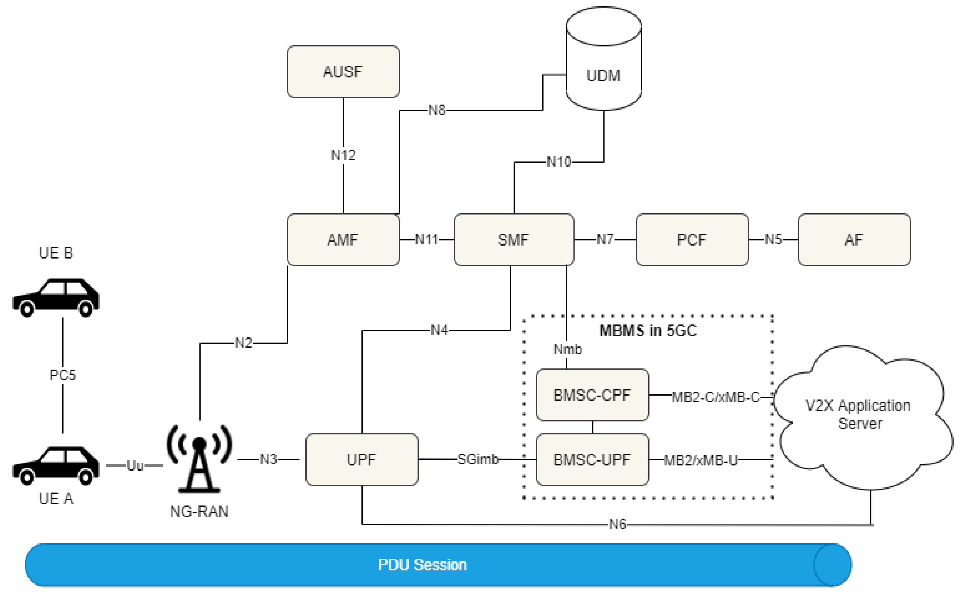
Figure 1 presents the 5G Architecture for V2X communications comprising information from [23,24]. In [23], the following network functions further support the V2X communication:
- The Policy Control Function (PCF) is responsible for providing authorization and policy parameters and retrieving V2X information from the Unified Data Repository (UDR);
- The Access and Mobility management Function (AMF) handles mobility management and obtains V2X subscription information from the Unified Data Management (UDM). Additionally, it retrieves PC5 QoS information from the PCF, and provides the aforementioned parameters to the NG Radio Access Network (NG-RAN);
- The V2X AS provides V2X parameters to the UE and the 5G core network. It receives UL data and sends DL data from/to the UE over unicast. Furthermore, it may request to receive notifications about potential QoS modifications in a specific geographic area. This information may be received through the Network Exposure Function (NEF).
In relation to the PC5 reference point, which relates to direct communication among the UEs, it is considered for V2X communication by both LTE and 5G-NR. In LTE’s Mode 3, the network allocates the resources to be used by the UEs. In Mode 4, the UEs autonomously select the resources to use for direct communication [25]. For LTE, the broadcast mode is the only supported communication mode. In 5G-NR, the respective communication modes are Mode 1 and Mode 2, which are enhanced compared to those of LTE, in order to improve the efficiency and provide QoS for the UEs. Additionally, broadcast, multicast, and unicast modes can be supported over the PC5 interface [23].
Regarding the 5G Uu interface, multicast and broadcast communication types have not yet been specified. In [24], various solutions have been proposed for providing multicast services. One of them is Multimedia Broadcast Multicast Services (MBMS), which has been used in E-UTRAN. According to the latter, multiple UEs receive the same content from a BS. However, such an approach requires multiple enhancements in the network so as to (a) enable the UEs to obtain the multicast IP, (b) enable the BS to transmit this content to multiple UEs, and (c) handle multicast session control. Note that in Figure 1 we have included the MBMS for reasons of completeness, although the exact solution will be specified in Release 17. As we will discuss later, the specific choices made for multicasting and broadcasting may have a significant impact on the communication delay.
The network functions that are responsible for the control of the multicast are the Session Management Function (SMF) and the Broadcast Multicast Service Center-Control Plane Function (BMSC-CPF). The SMF supports the MBMS bearer sessions and the IP multicast addresses allocation. BMSC-CPF connects with the V2Χ and provides the Temporary Mobile Group Identifier (TMGI) needed for the multicast communication. In addition, it manages the MBMS session and location-related information. For the user plane, the BMSC-User Plane Function (UPF) connects with V2X AS and transmits the MBMS-related data.
In [26], 5GAA has analyzed the aspects of predictive QoS (for 5G systems). Considering that V2X applications in the vehicle can request one or more communication links with a V2X AS, the latter can allocate various QoS levels to these links. However, due to varying network conditions, unanticipated QoS degradation may occur. In such cases, if the network can identify the QoS degradation in advance, it may enable the network or application to act proactively. Therefore, the notion of the “In-advance QoS Notification” (IQN) has been proposed. Finally, 5GAA has investigated in detail the support of communicating vehicles that are being served by different operators. Therefore, it has analyzed specific solutions for direct or infrastructure-based communication among vehicles [22]. In these cases, some form of inter-operator collaboration is needed, at least for the very demanding scenarios. This may include RAN sharing, regional roaming, local breakout points, or the dynamic exchange of configuration parameters.
The selection of the communication interface and the type of communication (i.e., unicast, broadcast, or multicast) have a significant effect on the experienced delay, but also on the needed network capacity, as we will explain in detail in the following sections.
4. Delay Analysis for V2X Communications
Latency is of pivotal importance for V2X systems given its relevance to the very fast reactions to potential hazards that are required. As shown in Table 2 some UCs require extremely low latencies (e.g., 3 ms). This is of course a very challenging goal for a cellular network. The latency that can be supported by Long-Term Evolution Advanced (LTE-A) and 5G-NR systems relates to inherent characteristics of the networks for specific control and user plane functionalities. Delay evaluation has been performed by 3GPP [27,28], 5GAA [22], and 5G Infrastructure Association (5G-IA) [29] for both LTE-A and 5G-NR. Moreover, the authors in [30] evaluated the IMT-2020 KPIs (including user and control plane delay) for 5G-NR following the assumptions provided by 3GPP [28] and 5G-IA [29]. In this paper, we provide a thorough analysis, with additional delay components that have not been presented in the aforementioned evaluations, such as handover, paging, and core network delay for 5G. The following sections provide detailed information for both the Uu and PC5 mode of communication in LTE-A and 5G-NR. For simplification, we only consider the Frequency Division Duplex (FDD) mode.
4.1. LTE-A Delay
Cellular networks have multiple components that contribute to the total system delay, including the control plane, core network, and user plane delay. These components are analyzed in [27] for V2X applications. In the rest of this subsection, the latency components for both the control and user plane are analyzed.
4.1.1. Control Plane
Control plane latency is related to the establishment of a signaling connection of a UE with the network (Radio Resource Control (RRC) connection establishment), paging, and handover (HO). The delay during these control functions may seriously affect the performance of an autonomous driving application, especially if the vehicles involved do not already have a connection to the network (i.e., IDLE RRC state).
RRC connection establishment switches the RRC protocol from the IDLE to the CONNECTED state [27]. To do this, the UE initially performs the Random Access Channel (RACH) procedure. It transmits a preamble to the Evolved Node B (eNB) to request resources to transmit in the UL channels. Then, once the resources are granted from the eNB, the UE performs the RRC connection establishment procedure [31]. This procedure may include security tasks. The overall procedure is decomposed in its steps and is presented in Table 3, together with the time required for each one of them. The time required for steps 11–14 is left null. This is due to the fact that steps 11–14 are performed concurrently with the steps 15–17 and are expected to finish before them, thus making the calculation of the delay for these steps irrelevant.
The overall delay of 50 ms can be considered as a significant delay, especially for V2X UCs that require a fast response time, even from vehicles that are in an RRC IDLE state.
Paging is the procedure performed by the network to locate a UE with the accuracy of a cell. It is an RRC procedure that occurs when incoming information (data, system information, etc.) is intended for a UE. As defined in [27], paging latency is considered from the point that a packet has already arrived at an eNB. The paging cycle varies from 320 ms to 2.54 s; an additional 2.5 ms of transmission and processing time is considered [27]. Upon reception of a paging message, a UE has to follow the RRC connection establishment procedure as described above. As the combined delay of paging and RRC connection establishment appears to be high, in relation to V2X UCs, V2X applications should take this into serious consideration.
For vehicles already involved in active communication (i.e., RRC CONNECTED), the disruption time during the execution of HOs needs to be considered. This procedure relates to the transfer of the UE context from one cell to another, the establishment of radio resources in the new cell, and possibly the switching of the core network’s established data paths. In LTE, the HO procedure is of the break-before-make type, meaning that there is a data interruption period where data transmission is paused; the interruption varies from 17 to 50 ms and it may even go up to hundreds of ms [33]. The HO procedure consists of the following phases, described in detail in Table 4:
- The HO preparation, starting with the transmission of the RRC measurement report from the UE to serving eNB. The eNB processes the request, coordinates with the neighboring eNB, and sends the HO command to the UE.
- The HO execution, which starts upon the reception of the HO command message from the UE. During this phase, the data transmission stops and the UE proceeds to RRC reconfiguration. Consequently, the UE attempts to reach the target cell via the RACH. The procedure is finalized when the UE transmits the RRC Connection Reconfiguration complete message to the target cell, and the target cell resumes data transmission.
It should be noted that LTE supports dual connectivity, where the UE simultaneously connects to two BSs. This may enable uninterrupted service continuity during an HO, at a penalty of using additional resources.
4.1.2. User Plane (Uu Interface)
User plane delay is the time needed by a UE from the transmission of a packet to its reception by another end device. During this procedure, a packet usually traverses through the core network (including the Evolved Packet Core (EPC) and V2X AS), which contributes to the total E2E delay. This delay consists of UL, DL, and network processing delays.
The UL delay in the radio access network is the time required for a message to be transmitted from a UE, until its reception by the eNB [27]. Three distinct cases can be identified in relation to UL transmissions, namely dynamic scheduling with/without a buffer status report (BSR) and semi-persistent scheduling (SPS) [27,34]. For dynamic scheduling, the UE sends a Scheduling Request (SR) through the Physical Uplink Control Channel (PUCCH) to the BS. The SR period is typically 10 or 1 ms; the average waiting time (SR/2) is used for evaluation [27]. Upon the reception of the SR by the eNB, the latter will process it and provide the UL grant to the UE, which will use it for the UL transmission. In the case where the UE provides the BSR, an additional time of 8 ms is required. For the SPS case, the eNB transmits the UL grant to the UEs, without the reception of SR, so the total time required for the SR procedure can be omitted. Therefore, the total delay for the SPS depends on the SPS period. The minimum SPS period is 10 ms, which should be augmented from the time required to transmit the data to identify the overall delay [27]. The afore-described analysis is presented thoroughly in Table 5.
In the DL, LTE can support both unicast and multicast/broadcast transmissions. The multicast/broadcast transmission mode is provided through MBMS, which is categorized as two service types: MBMS Single Frequency Networks (MBSFN) and Single Cell Point-To-Multipoint (SC-PTM). The former one is based on multi-cell transmission, meaning that UEs can receive the same message through different cells. In this case, the UE can exploit the multi-cell transmission, by combining the received messages, in the same way as multipath works, thus increasing the total reliability. In SC-PTM transmissions, the transmission area is restricted in one cell. The scheduling delay for SC-PTM is lower, since synchronization from multiple cells is avoided. Table 6 presents the DL delay, reported in [27], and includes both unicast and multicast/broadcast transmission. In general, the same values are considered for both transmission modes, except the scheduling periods. For MBSFN, the scheduling period refers to the Multicast channel Scheduling Period (MSP) and the SC-PTM scheduling period (SSP) is employed for single cell transmission. The former uses the Multicast Traffic Channel (MTCH) to convey the data. In contrast, whilst SC-PTM delivers the data through the Physical Downlink Shared Channel (PDSCH).
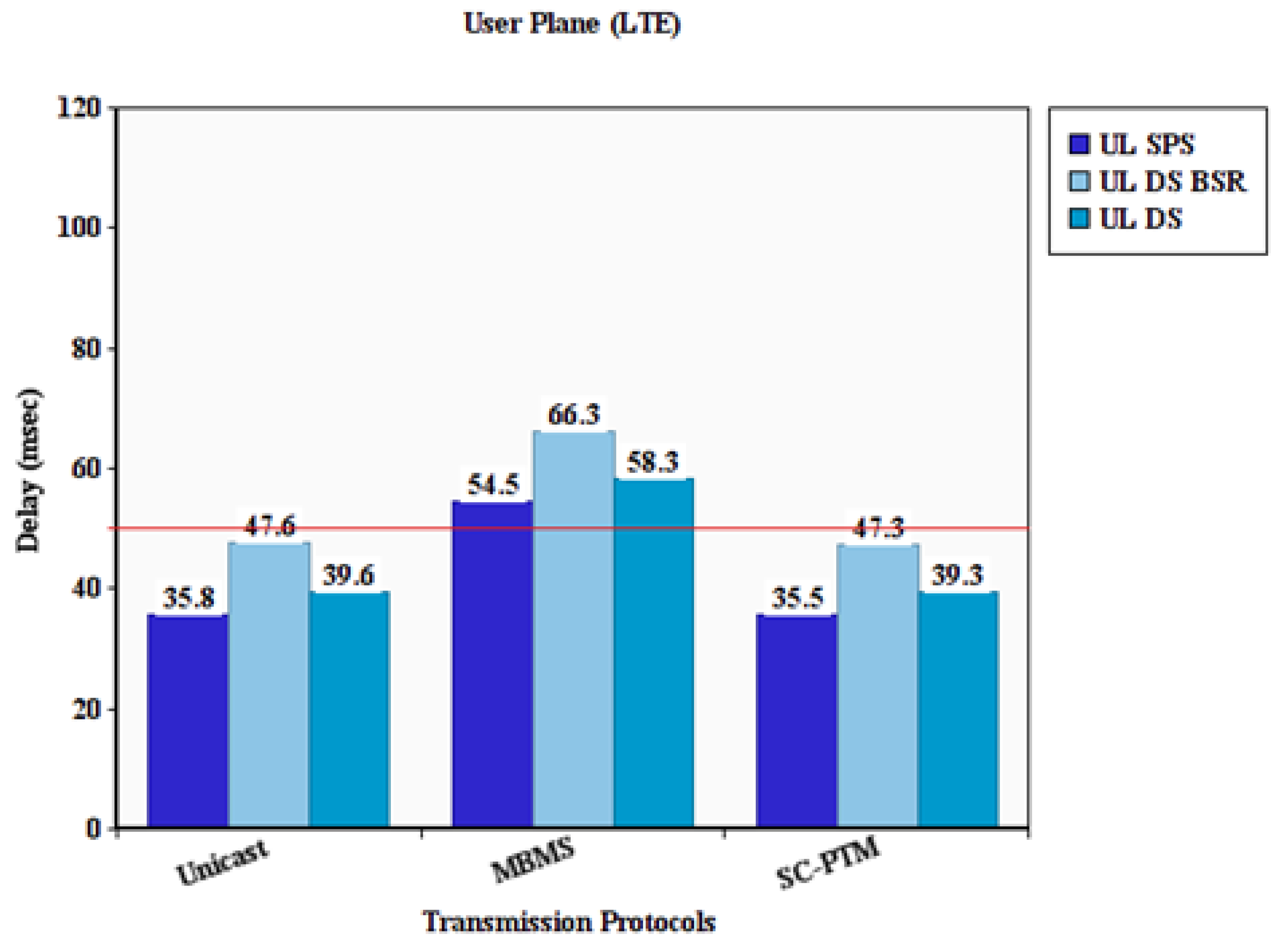
Regarding the delay in the core network, this is also referred to as network processing delay. In LTE, the packet needs to traverse through network components (i.e., Serving Gateway S-GW and Packet Data Network Gateway P-GW) to reach the destined eNB. For multicast/broadcast transmissions, the only difference that occurs in the DL phase is when the packet is being communicated through the Broadcast-Multicast-Service Centre (BM-SC). However, the network processing values for unicast and multicast/broadcast are the same—20 ms [27]. Figure 2 provides the total delay in the cases where BSR is used (UL DS BSR) or not used (UL DS) and for SPS. Moreover, all types of communication, including unicast, MBMS, and SC-PTM, are used. The E2E delay can be modeled as follows:
To give an example, we can assume a unicast transmission with SPS. The equals 8 ms (Table 5), the for unicast mode is 7.8 ms (Table 6), and the is always 20 ms, leading to = 35.8 ms, as presented in the figure below.
Note that local breakout schemes enable the exchange of packets in a confined area and avoid routing through the core network. The Selected IP Traffic Offload (SIPTO) solution is an approach that could be considered for V2X communication as it would avoid the delay when crossing the core network, but it cannot provide an uninterrupted service under all scenarios [35].
4.1.3. User Plane (PC5 Interface)
As mentioned earlier, some of the late LTE’s versions supported direct communication between UEs, through the so-called PC5 interface. PC5 used for vehicular communications is categorized as two transmission modes, namely Modes 3 and 4 [22]. Mode 3 refers to network scheduled transmission, whereas Mode 4 refers to transmission on autonomously selected resources. In Mode 3, the eNB is responsible for providing the UEs with control information, including the type of scheduling [22].
Mode 3 uses dynamic scheduling with BSR or semi-persistent scheduling. Dynamic scheduling with BSR follows the same principle as in the UL transmission case, omitting the last two steps (including UE transmission and eNB reception). In SPS, the UE may provide feedback information to the eNB, in order to allocate the SPS resources effectively and reduce the transmission latency. The latter can be achieved if the scheduling configuration is synchronized with the packet arrival time. Consequently, the data transmission occurs immediately [22].
At this point, it should be mentioned that when a UE is in the RRC IDLE state, it can only transmit a packet in Mode 4. A UE will have to switch to the RRC CONECTED state to transmit using Mode 3. This implies that when the UE has delay-critical data to transmit, this additional burden has to be considered for Mode 3 (50 ms for RRC connection). On the contrary, this delay is optional for the UE in Mode 4, with the limitations of the local view of sensing, which may phase collisions on the receiver’s side (e.g., the hidden terminal problem). Another control plane component that should be considered for both modes is the transmission of UE sidelink information for a resource configuration request which occurs when the UE receives the RRC reconfiguration message from the eNB. The assumption for this delay component is 29.1 ms [27].
The sensing period and the SPS delay relate to sensing windows and scheduling windows, respectively, which may vary [22]. The analysis of these steps is presented in Table 7 considering the min., mean, and max. values of the potential delays; the RRC connection delay is not considered, since it is assumed that the UE is already in a condition to transmit.
4.2. 5G-NR Delay
As mentioned in the introductory sections, 3GPP has considered that only the initial UCs of V2X will be tackled by the 4G system. The 5G system should handle the more demanding UCs. Therefore, 5G-NR introduces flexible resource allocation in the physical layer [36], including different Subcarrier Spacing (SCS), Orthogonal Frequency Division Multiplexing Symbol (OS) durations, and Cyclic Prefixes (CPs), usually referred to as numerologies. In the time domain, physical transmissions correspond to frames with a 10 ms duration, which in turn are divided into ten subframes with a 1 ms duration, as in LTE. One slot consists of 14 OS and subframes might have several slots, depending on the numerology (i.e., SCS). For example, a subframe is equal to one slot in the case of 14 OS using 15 KHz SCS (i.e., fixed transmission parameters in the LTE frame structure). A physical resource block (PRB) is composed of 12 consecutive subcarriers for one OS, contrary to LTE, which corresponds to a fixed slot of 0.5 ms (i.e., PRB = 12 subcarriers × 1 slot).
Resource mapping types [37] indicate how the Physical Uplink Shared Channel (PUSCH) and PDSCH are allocated throughout the slot. For PUSCH, mapping type A indicates that the allocation always occurs at OS 0 in the slot, while in mapping type B, it might start midway through the slot. PDSCH follows the same frame structure for both mapping types. Therefore, Demodulation Reference Signals (DM-RS) are used in PDSCH allocation for channel estimation and the demodulation of physical channels. Type A implies that DM-RS are located in the second or third symbol of a slot and type B implies that DM-RS are located in the first symbol of the PDSCH allocation. Having the DM-RS at the beginning of the allocation makes the demodulation faster. The delay analysis below considers both control and user plane functions.
4.2.1. Control Plane
In order to reduce the need for repeated UE context retrieval from the network, every time a UE performs an RRC Connection Request, 3GPP’s Release 15 introduces a new state in respect to the RRC protocol called RRC INACTIVE [38]. The basic feature of this state is that a UE maintains the connection with the core network. The Access Stratum context is stored in the UE and the gNB. This new state is beneficial for the overall delay, since the signaling for the transition in the RRC CONNECTED state is shortened and the UE context is already available in the gNB.
According to [28], control plane latency is defined as the time required for the transition of the UE from the RRC INACTIVE to RRC CONNECTED state. The calculation of the control plane latency is based on the following assumptions. The waiting time for the transmission of a preamble through RACH is considered to be T1 = 0 ms. However, the start time for the transition from the “battery efficient state” is not defined, so the RACH scheduling period could be included, affecting the overall delay. The time required to transmit the preamble T2 depends on different Physical Random Access Channel (PRACH) symbol lengths (i.e., 2, 6, and 14). The next step is preamble detection and processing in the gNB, calculated as T3 = tgNB/2. The processing time in the gNB is given by [37], calculated as
where N2 depends on SCS and can be found in Table 6.4-1 and Table 6.4-2 in [37] for UE processing capability 1 and UE processing capability 2, respectively; μ is the numerology; and is a constant to relate the NR basic time unit Tc = 0.509 ns and LTE basic time unit Ts.
After the time required for the first frame alignment TFA1, the gNB sends the RA response and the total time T4 depends on the configuration (slot or non-slot). The UE processing delay T5 involves the decoding of the scheduling request, Cell Radio Network Temporary Identifier (C-RNTI) assignment, and the L1 encoding of RRC resume request. The UE processing time is calculated [39] as
where NT,1 (Table 5.3-1 [37]) is the time required to transmit N1 symbols for PDSCH reception with processing capability 1 and an additional DM-RS configuration and NT,2 (Table 6.4-1 [37]) is the time required to transmit N2 symbols for PUSCH reception with processing capability 1. Moreover, Twait is the average waiting time between the reception and transmission of data, which is assumed to be 0.5 ms.
Once the RACH procedure has been completed and after frame alignment TFA2, the UE transmits the RRC Resume Request message and the total time T6 also depends on the configuration (slot or non-slot). The assumption for the gNB processing the L2 and RRC request is T7 = 3 ms. After frame alignment TFA3, gNB responds with the RRC resume message alongside the UL grant and the time T8 depends on the configuration. The UE processing (L2 and RRC) is T9 = 7 ms. The time required for transmission of the RRC Resume Complete message is omitted, since the transmission occurs at the beginning of the subframe with the actual data T10 = 0 ms. The above procedure results in different values for the control plane delay that range from 11.3 to 17 ms, depending on the TTI length, subcarrier spacing, resource mapping type, and UE capability, analyzed in [28].
Note that a UE can support an RRC INACTIVE state, even if attached to an eNB, but only if the eNB is connected to the 5G Core network [31]. In [28], 3GPP evaluates the control plane latency, compared to LTE-A, for the transition of the UE from the RRC INACTIVE to RRC CONNECTED state (Table 8)—the impacted values are denoted in bold. The evaluation follows the same sequence as the transition (RRC INACTIVE-RRC CONNECTED), analyzed for the 5G-NR above. The only difference is that for the 5G-NR case, there are a variety of numerologies. In comparison to Table 3, the processing values for eNB and UE have been reduced [28]. As for the RACH scheduling period and the transmission of the RRC Connection Resume Complete message, the assumption is the same as in the 5G-NR case (0 ms).
In relation to the paging cycle, it is significantly more flexible in 5G systems than in LTE, varying from 10 ms to 10.24 s [38]; additional transmission and processing time should be considered, which would be in the range of 1–2 ms. Upon the reception of a paging message, a UE has to follow the RRC connection.
Finally, 5G supports dual connectivity, as was the case in LTE. This feature can be used to minimize the HO delay at the penalty of using more radio resources.
4.2.2. User Plane (Uu Interface)
The overall user plane latency for 5G is different for the UL and the DL. It is worth mentioning that for DL, only the unicast mode is supported as of now by 3GPP standards. The description for MBMS referenced in Section 3 is only a proposal adapted from [24]. 3GPP has not yet standardized the MBMS architecture for 5G-NR.
For the UL procedure, grant-free transmissions can be used in order to reduce the delay [28]. Since the UL grant is omitted, the UE only needs to process the data and wait for frame alignment. The packet transmission delay depends on the length of the OS needed. The gNB processes the data through PUSCH. However, grant-free transmissions face the inherent problem of potential collisions on the receiver’s side. For the DL, the gNB processes the data and waits for frame alignment. The packet transmission delay depends on the OS length.
In case there is an error in the transmission/reception, the Hybrid Automatic Repeat reQuest (HARQ) protocol is used for proper reception, which is based on retransmissions. In UL, the gNB schedules the retransmission through the Physical Downlink Control Channel (PDCCH). Upon the decoding of the control information from PDCCH from the UE, the latter needs to repeat the UL procedure. In DL, the UE transmits an ACK/NACK to indicate proper reception or failure. The user plane procedure can be calculated as follows [30]:
where is the probability of retransmission. The first transmission can be calculated as follows:
where is the processing time in the gNB (same as the control plane), is the time needed for frame alignment, is the actual transmission of data, and is the processing time in the UE:
where depends on SCS and can be found in Table 5.3-1 and Table 5.3-2 in [37] for UE processing capability 1 and UE processing capability 2, respectively. If an error occurs, the UE needs to ask for a retransmission (HARQ) and the time can be calculated as follows:
where requires 1 OS. After receiving and processing the HARQ request, the gNB retransmits the content (in the case of DL):
In [40], 3GPP employs a specific numerology (i.e., UE capability 2, non-slot-based PDSCH/PUSCH allocation of 2 OS) to meet the advanced V2X UC requirements. The values are presented in Table 9.
The previous analysis for LTE considered the E2E values. However, this is not available in 5G systems, since in the technical specifications and the literature, there are no agreed values for the core network delay. In [22], 5GAA assumes a 3 ms delay each time a packet traverses through an interface in the EPC. Moreover, using a local breakout scheme with a standalone Local Gateway (L-GW), the overall core network delay for LTE may be reduced from 20 to 12 ms [22]. In the case of the 5G core network, the packet needs to traverse from gNB to UPF through the N3 interface and subsequently from UPF to the V2X AS through the N6 interface (i.e., for unicast mode) [23], always assuming that the UE is in the RRC CONNECTED state and the Protocol Data Unit (PDU) session is established. In order to provide a complete picture of the E2E delay, we assume a 3 ms delay for each interface, as in [22]. The assumptions for 5G-NR evaluation are presented in the UC Delay Evaluation Section.
4.2.3. User Plane (PC5 Interface)
3GPP in 5G-NR Release 16 devoted significant effort to the development of solutions related to V2X direct communications, in order to overcome some of the key deficiencies of LTE PC5, related to unicast communication among UEs and QoS management. In parallel, enhancements have been provided to reduce the latency and increase the reliability by reducing collisions [41].
As mentioned in Section 1, in 5G-NR, sidelink communication comprises Mode 1 and Mode 2, which are direct enhancements of LTE Mode 3 and Mode 4, respectively. Therefore, 5G-NR Mode 1 refers to communication where the UE transmissions are scheduled by the gNB, whereas in Mode 2, the UE autonomously selects resources [42].
In 5G-NR, the UE can transmit on a per slot basis (the frame length is 10 ms and the subframe 1 ms), which has a length of 1, 0.5, 0.25, and 0.125 ms for subcarrier spacing of 15 (FR1), 30 (FR1), 60 (FR1 and FR2), and 120 kHz (FR2), respectively, thus facilitating a reduction in the E2E delay [42].
Regarding the resource allocation, in Mode 1, there are two options. In the first one, the UE performs the scheduling grant request once the data are available, whereas in the latter, the UE requests the schedule grant request in advance (so-called grant-free transmission) [42]. In the grant-free case, the UE reserves the resources in a periodic manner. As in LTE’s Mode 3 transmission, if the UE is in the IDLE state, it should turn to CONNECTED. This procedure, however, is only needed in the first scheduling grant request, and for the rest of the transmissions, it will not introduce an additional delay. The delay cost of this case is the same as in the Uu transmissions.
In Mode 2, the UE can start transmitting from the IDLE state. Once the data are available, the UE performs the sensing procedure and the resource selection to identify the less occupied resources and select the most appropriate to use [41]. Then, using the Sidelink Control Information (SCI) message, it reserves the particular resource(s) to be used. In order to reduce the latency, in the case of collisions, the UE may reserve resources for the retransmissions from the initial selection. In case other UEs with more urgent services need to transmit a message (or a set of messages), they may reserve an already reserved resource; in this case, the UE initially accessing the spectrum resources will need to reselect resources, thus increasing the latency. Interestingly, to perform QoS control (especially in Mode 2), the UEs may report (according to their configuration) the channel busy ratio and the channel occupation ratio to the gNB; the latter according to these will define the set of spectrum and sensing parameters of the UE, thus impacting the delay [41].
4.3. UC Delay Evaluation
The purpose of the previous analysis was to identify which of the UCs described by 3GPP and 5GAA can be covered by the existing systems and the gaps. Considering the analysis on LTE and 5G and comparing the results to the UC requirements as they have been described in Table 2, we produced Table 10 and Table 11. The former considers the 3GPP delay requirements and captures the achievable delay with LTE-A solutions, whereas the latter considers the same requirements that can be achieved by the 5G-NR. ✓ means that the requirements are successfully met, whereas ✕ is used for failures. Note here that for some UCs, there are different scenarios with regard to the automation levels. For instance, Infrastructure-based Perception Environment considers 3 ms for full automation and 100 ms for partial automation. ▽ indicates that the specific UC can only be fulfilled for a lower level of automation.
As can been seen in Table 10, LTE-A can serve only a few of the advanced driving UCs. Some of them can indeed be supported, but only for the lower levels of automation. This was to be expected as the advanced V2X UCs are expected to require E2E delay values that are much lower compared to what LTE-A systems can offer.
In the case of 5G-NR, we have selected the following numerology, which is one of the potentially good candidates for V2X communication according to [40]. We have assumed resource mapping of type B, a zero initial error probability, 2 OS, and 30 KHz SCS. We have also used the assumption from a packet that faces a 3 ms delay each time it crosses a network interface (e.g., gNB to UPF). To obtain a complete picture, we have assumed delays of LTE-A in the case of multicast communication as there is currently no such capability in 5G networks. In all cases, we also consider a link to the V2X application server. Table 11 presents the expected delay in the case of (a) E2E unicast communication (packets are crossing two UPFs), (b) a local breakout scheme being used (only one UPF is used), (c) Multicast through the MBMS, and (d) Multicast through SC-PTM. The results are compared against the V2X requirements.
Based on this assumption, we observe that compared to the results of LTE-A, 5G-NR can indeed support many more UCs. However, it is worth noting that even with a small core network delay, many of the 3GPP UCs cannot be covered, even by 5G networks. This is because multiple delay-contributing network components (e.g., crossing multiple network interfaces among network components in the core network and RRC establishment) have been improved, but not to the extent that a total end-to-end delay of less than 10 ms is reached. Therefore, innovative solutions are still needed for beyond 5G/6G networks to reach these desired delay values.
5. 5G Capacity Analysis for V2X Communications
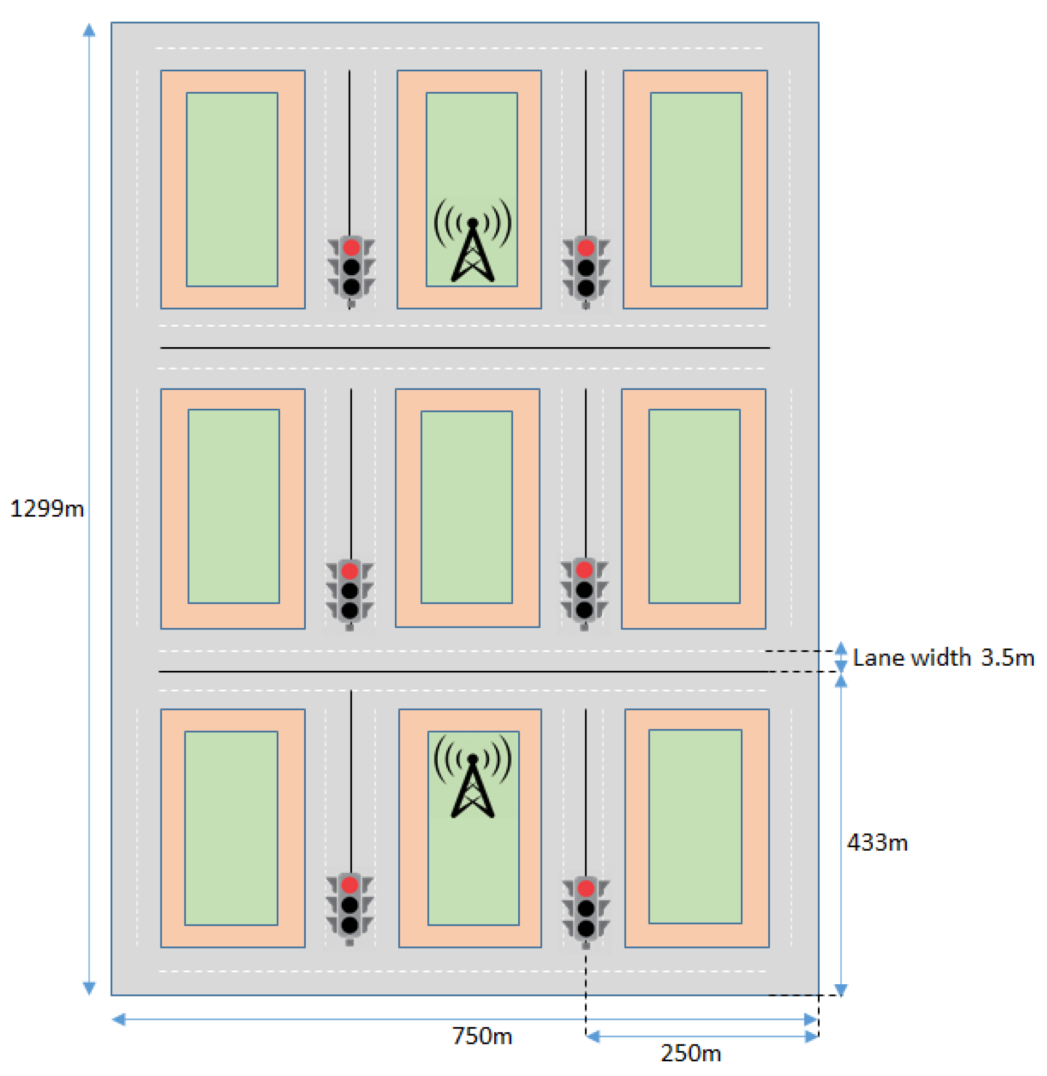
In this section, we evaluate the spectrum needed to support the V2X UCs of Table 1. Our analysis adopts the framework provided by 5GAA in [20]; however, it also provides a complete picture for the advanced UCs discussed in Section 2 for three distinct scenarios that assume different vehicles’ density in the considered area. To analyze the capacity requirements, we have considered the Urban Grid Environment [43], as shown in Figure 3.
The urban grid size is 1299 m × 750 m with lanes of 3.5 m. The vehicles in the urban grid are assumed to be stationary (red light) in the vertical lanes, or could be moving (green light) in the horizontal streets and in the perimeter lanes. For calculating the number of stationary vehicles, we have considered an average vehicle length of 4.5 m and a bumper-to-bumper separation of 1.5 m. This means that there is one car at every 1.5 + 4.5 = 6 m per lane in the stationary direction of the grid. Across a total of 24 lanes, the total number of stationary vehicles is [(433 − 14) × 24]/6 = 1676.
Regarding the number of moving vehicles, three cases are considered for different vehicle speeds, as shown in Table 12. The assumed inter-vehicle spacing is given as the sum of the typical vehicle length (4.5 m) and a bumper-to-bumper separation of 20.8, 10.4, and 3.5 m for vehicle speeds of 30, 15, and 5 km/h, respectively, which corresponds to a time to collision of 2.5 s.
We have assumed that stationary vehicles are in a state that does not require services, so we only take into consideration the moving vehicles for the spectrum analysis. We also assume that this area is covered by two gNBs, each of which has three sector antennas. The Inter Site Distance (ISD) between the gNBs is 500 m and the size of each sector is . In the following analysis, we have also evaluated the cases where this geographic area is to be covered by 3 or 4 gNBs.
Following the analysis in [20], the succeeding categories have been distinguished. The bandwidth B needed for repetitive V2V services that require the transmission of broadcast/multicast/unicast messages is given by
where is the number of vehicles actively participating in a V2X UC; T is the throughput of the V2X service; a is the activity factor, e is the spectral efficiency, assumed to be 1.2 for the UL 4 for the DL and 0.6 for the sidelink; and u is the channel utilization factor equal to 0.336 for all UCs. This formula is applied to all UCs apart from UCs 2, 3, and 5, as reported in Table 1. For the activity factor, we have assumed a value of 1 for all UCs (as they are considered to be in a fully communicating state), apart from “Platooning” and “Lane Merging” (0.1) and “Collective Information Sharing” (0.8), as also assumed in [20].
The spectrum needs for V2N UCs are given by
where T is the required data rate per link in bit/s, is the density of (transmitting or receiving) vehicles served per unit area in km−2, e is the sector spectral efficiency in bits/s/Hz, and A is the area of the serving sector.
To introduce stochastic analysis in our evaluation, we used a program in MATLAB that resulted in circa 5% of all available vehicles being active in each V2X UC, apart from “Lane Merging” and “Emergency Trajectory Alignment” (3%) and “See Through for Passing” (1%), and we have only considered one vehicle per sector to be remotely operated.
The estimated spectrum needs per gNB sector for the UCs examined in this section are summarized in Table 13.
From the above table, it is clear that most of the UCs have limited bandwidth needs. Only a few of them require the transmission of a significant amount of information (i.e., “Remote Driving”, “Infrastructure-Based Perception of Environment”, “Collective Information Sharing”, and “See Through for Passing”). It is exactly these UCs that dominate the spectrum needs. It is important to note that these UCs mainly use the SL or the UL, where the spectral efficiency is much lower compared to that of the DL’s.
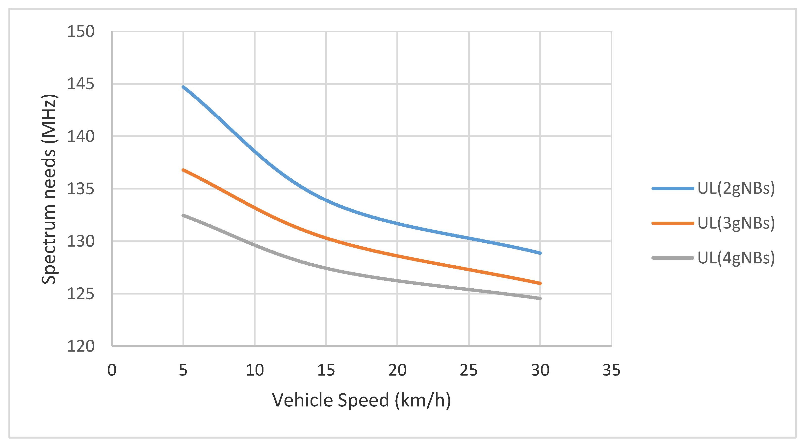
The above results consider the urban grid environment with the deployment of 2 gNBs, as shown in Figure 3. To visualize the spectrum needs in an ultra-dense environment, we have also evaluated the case where 3 and 4 gNBs have been deployed to cover the same area. Figure 4, Figure 5 and Figure 6 present these results for the DL, UL, and sidelink, respectively. Since only a few vehicles are involved in V2N UCs and the DL data rate requirements are low, the resulting DL spectrum requirements are also notably low. As mentioned above, the DL has a good spectral efficiency value.
The UL spectrum needs are heavily dominated by two UCs, namely “Remote Driving” and “Infrastructure-based Perception of Environment”. For these two UCs, we have adopted the evaluation assumption of [20], that only a small number of vehicles will execute such services in this area (i.e., one vehicle for “Remote Driving” per sector) and only a single group of sensors will be transmitting on the UL for the “Infrastructure-based Perception of Environment”. The spectrum needs for each of these two UCs were 30 and 91.67 MHz, respectively. The contribution of the “State and Sensor Map Sharing” depends on the number of vehicles using the service in the area.
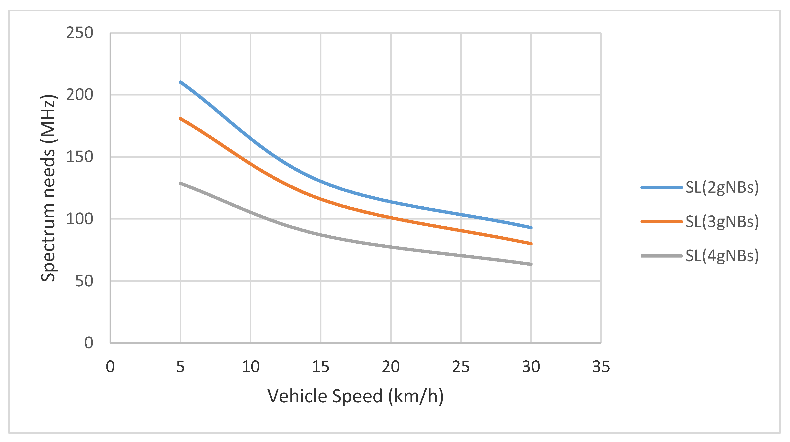
It is worth noting that V2V communication is expected to be used for most of the considered advanced UCs. The spectrum needs for UCs 1, 4, 6, 9, and 10 are relatively modest, due to low data rate requirements, and can be more or less addressed via about 10 MHz in an urban environment. On the other hand, UCs such as “Collective Information Sharing”, “See Through for Passing”, and “Cooperative Driving” dominate the sidelink spectrum needs and raise the system’s needs to 210 MHz in the case of 2 gNBs combined with a high traffic urban environment.
As the spectrum needs of a mobile communication network are in principle the sum of the spectrum needs of each individual supported UC, those that demand the exchange of a significant amount of information (e.g., high-definition videos and maps) will create significant challenges.
In conclusion, a critical factor that needs to be addressed is the significant improvement of the spectral efficiency for the UL and SL. This means that the vehicles should be equipped with more advanced modems capitalizing the benefits of Multiple Input-Multiple Output (MIMO) systems.
6. Open Issues and Future Trends
Based on the previous analysis, it is evident that current cellular networks are able to support a significant number of V2X UCs, but are still unable to fully support the vision of fully autonomous driving under any environmental conditions. Indeed, LTE networks can provide for services that have moderate requirements in terms of throughput and delay, but need to address major challenges, such as the physical layer structure, synchronization issues, MBMS challenges, and resource allocation and security issues, which are thoroughly analyzed in [44], before the massive exploitation of vehicular communications. However, not even 5G networks can fully support UCs with stringent requirements with today’s technological solutions.
As far as the delay is concerned, the analysis we provided in this paper has clearly indicated that in LTE, the control plane delay required to switch to the CONNECTED state is circa 50 ms (or 20 ms if the 5G core network is used), whereas the user plane delay varies from 7 to 10 ms for unicast communication over the Uu interfaces up to 26 or 55 ms if the sidelink is to be used. Additionally, a considerable 26 ms user plane delay is experienced if MBMS is used. LTE network’s limitations, evaluated through network simulations, are presented in [45], providing the limits of different parameter sets with regard to the requirements of V2X-based applications. As expected, LTE is not a suitable solution for tackling the advanced 3GPP requirements for fully autonomous driving. Design principles for latency-aware V2X services, such as “one-OFDM-symbol” TTI (1/14 TTI) and sustained RRC connections during V2X services, are proposed in [46] to satisfy the feasibility of V2X services in terms of latency.
5G-NR has considerably improved the control plane latency (reduced it to 11.3 ms) and is able to provide just a 1 ms delay for user-plane communication inside the radio access network (i.e., measured as the time required to transmit data from a vehicle to a BS and back to another vehicle). However, the control plane delay is significant and usually not taken into consideration when evaluating the delay for V2X communications. The assumption that all vehicles will always be connected to the network at all times does not seem so realistic due to the scarcity of the spectrum. Therefore, in advanced cases, the extra delay of 11.3 ms required to switch from the RRC INACTIVE to CONNECTED state may result in a significant deviation from the expected performance of the network. A potential solution would be that for some UCs, a connectionless transmission of brief messages for a short period of time could be used to eliminate this delay. This will significantly impact the way V2X services will be designed to operate and will have a big impact on standardization activities.
As existing requirements suggest that the desired V2X communication delay for the user plane should be in the range of 3 to 10 ms for advanced UCs, it is rather significant to support local breakout schemes and avoid traffic passing through the core network or reaching centralized application servers, where statistical multiplexing from a huge number of vehicles may fail to guarantee the required QoS. It is important to remember that for most V2X UCs, the data have a local significance and they do not need to propagate across large distances. Therefore, future cellular networks should further investigate solutions to support local break-out schemes and find solutions for fast data transmission in specific cases (e.g., collision avoidance in urban crossroads [47]). Mobile edge computing (MEC) is a key technology for addressing this challenge. The authors in [48] evaluate C-V2X communications assisted by MEC for the vulnerable road users use case in a two-lane freeway scenario. The evaluation considers LTE coverage (i.e., Uu interface) with the MEC host collocated with a serving eNB. Additional transport and core network delays are adopted from a realistic LTE environment with commercial terminals. The gain reported compared to conventional LTE (i.e., w/o MEC) is in the range of 66–80%. However, the massive deployment of MEC or local UPFs is expected to significantly increase the cost and management complexity of the network. Additionally, issues related to the security of data located closer to the edge of the network should be addressed. In the case of multiple operators, the core network delay becomes even higher, making some UCs rather unlikely to be deployed in multi-operator environments. RAN sharing or regional roaming could be considered as potential solutions. However, this requires appropriate agreements between the operators that are not always easy to achieve.
The design of a 5G MBMS is of paramount importance as its counterpart 4G system has been designed for Mobile Broadband (MBB) communication and its use will incur intolerable delays. This is expected to be addressed by 3GPP in Release 17 [49].
Potential future solutions may take advantage of additional contextual information. Note that in fully autonomous driving, a network entity (e.g., the V2X AS) is expected to know the path a vehicle will follow in the near future. Sharing this contextual information with the network control functions (e.g., RRC, scheduling, etc.) may minimize the delay (e.g., control plane delay such as paging or handover) and simultaneously optimize the experienced QoS.
Further network enhancements applied to minimize the delay should be considered to avoid treating packets at the IP layer as the information is so localized that it could be communicated in a layer-2 switch function to the neighboring vehicles or the neighboring BSs [50]. This requires the 5G gNBs to operate as switches in the user plane, which is a considerable difference from today’s systems.
Additionally, the case of border crossing should be considered when it comes to delay analysis. Current standardization solutions [51] support inter-operator HO, but these solutions are rather complex and require additional agreements between the operators, since they need to expose their AMF deployment to other operators (which may be competitors). In regions like Europe, where vehicles may cross multiple borders in a short period of time, simpler solutions would be highly desirable. If vehicles are to be supported by multiple operators then some unneeded delay may be experienced that is not easily addressable until some out-of-the box ideas are considered, such as force regional roaming [52], which may have some interesting implications in the operator business models themselves.
In future scenarios, especially in urban areas where the density of vehicles will be high, the capacity is going to be the major issue. LTE will struggle to support a fraction of vehicles, even for the most moderate usage of UCs. Apparently, such a problem will not appear from day one, but as more and more vehicles start communicating, this problem will become evident. Fully autonomous driving is highly unlikely to be easily supported, even with the current 5G technology, as indicated from our analysis.
Most of the advanced V2X UCs have modest spectrum requirements. However, use cases that demand the exchange of a significant amount of information (e.g., high-definition videos and maps) will create significant challenges. To address this, one possible way forward would be to merge several UCs that attempt to improve the vehicle’s perception of the environment. Moreover, smart techniques employed to compress the information needed to be transmitted are expected to play an important role. The extensive use of the multicasting/geo-casting mode of communication will further minimize the need for the spectrum.
PC5 communication (both in LTE and 5G) will improve the capacity situation, given that short-range communication will enable higher frequency reuse, but it will not fix the problem. Considering UCs such as “Remote Driving” and “Cooperative Driving”, multiple networks may need to communicate with the application servers located in the core network and in these cases, PC5 will not really be an option at all.
Another critical factor that needs to be addressed is the significant improvement of the spectral efficiency for the uplink and sidelink. This means that the vehicles should be equipped with more advanced modems capitalizing the benefits of Multiple Input-Multiple Output (MIMO) systems.
Ultra-densification of the network is the obvious solution for supporting the advanced V2X UCs. However, to support such a number of vehicles in an urban environment would require a significant number of BSs, the Capital Expenditure (CAPEX) of which will be significant. Moreover, this would result in a significant number of HOs and a dramatic increase of the respected signaling. This suggests that new HO schemes should be considered, together with the solutions, in order to increase the computing performance at the edge of the network [53] and centralized RAN solutions. A possible solution for handling HOs would be to use contextual information about the movement of the vehicles, as mentioned before. In this way, the access network can act proactively and minimize any disruption time, without requiring dual connectivity at all places.
Finally, one potential solution worth investigating further to provide more mature results is the use of VLC for V2X [54] and THz communications [55]. The solutions can provide significant segments of unused spectrum, but current technological obstacles need to be bypassed to render them a viable solution for V2X communications.
7. Conclusions
In this paper, we have presented the key requirements of advanced autonomous driving UCs, as provided by the two main international organizations, namely 3GPP and 5GAA. We have also provided a thorough delay and capacity analysis for these UCs considering both the LTE and 5G networks.
As the paper focused on the analysis of the most demanding services, we have identified current shortcomings in network technologies and also discussed research areas that could be further investigated. V2X communication will pick up pace in the following years. Therefore, all technological barriers should be lifted long before the number of vehicles accessing such services reaches a point that will make fully autonomous driving an unstable service. As a next step in our work, we plan to perform thorough simulations to validate these preliminary results for delay and capacity.
Author Contributions
Conceptualization, A.K. (Alexandros Kaloxylos); Data curation, A.K. (Athanasios Kanavos), D.F. and A.K. (Alexandros Kaloxylos); Formal analysis, A.K. (Athanasios Kanavos) and D.F.; Investigation, A.K. (Athanasios Kanavos), D.F. and A.K. (Alexandros Kaloxylos); Supervision, A.K. (Alexandros Kaloxylos). All authors have read and agreed to the published version of the manuscript.
Funding
This research received no external funding.
Conflicts of Interest
The authors declare no conflict of interest.
References
- SAE Document J3016_201806. Taxonomy and Definitions for Terms Related to Driving Automation Systems for On-Road Motor Vehicles. Available online: https://www.sae.org/standards/content/j3016_201806/ (accessed on 15 June 2018).
- 3GPP TR 22.886 (V16.2.0). Study on Enhancements and Support for 5G V2X Services, Release 16 December 2018.
- 3GPP TR 22.885 (V14.0.0). Study on LTE Support for Vehicle to Everything (V2X) Services, Release 14 December 2015.
- 3GPP TS 36.211 (V14.0.0). Physical Channels and Modulation, Release 16 December 2019.
- 3GPP TR 36.788 (V15.0.0). User Equipment (UE) Radio Transmission and Reception, Release 15 June 2018.
- 3GPP TS 22.186 (V16.2.0). Enhancement of 3GPP Support for V2X Scenarios, Release 16 June 2019.
- METIS 2020, Deliverable D1.5 (ICT-317669-METIS/D1.5). Updated Scenarios, Requirements and KPIs for 5G Mobile and Wireless System with Recommendations for Future Investigations. Available online: https://metis2020.com/wp-content/uploads/deliverables/METIS_D1.5_v1.pdf (accessed on 30 April 2015).
- METIS 2020—II, Deliverable D1.1 (ICT- 761510-METIS-II/D1.1). Refined Scenarios and Requirements, Consolidated Use Cases, and Qualitative Techno-Economic Feasibility Assessment. Available online: https://metis-ii.5g-ppp.eu/wp-content/uploads/deliverables/METIS-II_D1.1_v1.0.pdf (accessed on 31 January 2016).
- NGMN 5G White Paper. Available online: https://www.ngmn.org/wp-content/uploads/NGMN_5G_White_Paper_V1_0.pdf (accessed on 17 February 2015).
- 5GCAR, 5GCAR Scenarios, Use Cases, Requirements and KPIs. Available online: https://5gcar.eu/wp-content/uploads/2017/05/5GCAR_D2.1_v1.0.pdf (accessed on 31 August 2017).
- 5G CroCo, Deliverable D2.1 Test Case Definition and Trial Site Description Part 1. Available online: https://5gcroco.eu/images/templates/rsvario/images/5GCroCo_D2_1.pdf (accessed on 30 June 2019).
- 5G CARMEN Use Cases. Available online: https://5gcarmen.eu/use-cases/ (accessed on 10 January 2021).
- 5G CroCo, Deliverable D5.1 Description of 5GCroCo Business Potentials. Available online: https://ec.europa.eu/research/participants/documents/downloadPublic?documentIds=080166e5c7494fd6&appId=PPGMS (accessed on 10 September 2019).
- Elayoubi, S.E.; Fallgren, M.; Spapis, P.; Zimmermann, G.; Martin-Sacristan, D.; Yang, C.; Jeux, S.; Agyapong, P.; Campoy, L.; Qi, Y.; et al. 5G service requirements and operational use cases: Analysis and METIS II vision. In Proceedings of the 2016 European Conference on Networks and Communications (EuCNC), Athens, Greece, 27–30 June 2016; pp. 158–162. [Google Scholar] [CrossRef]
- Boban, M.; Kousaridas, A.; Manolakis, K.; Eichinger, J.; Xu, W. Connected Roads of the Future: Use Cases, Requirements, and Design Considerations for 5G V2X. IEEE Veh. Technol. Mag. 2018, 13, 110–123. [Google Scholar] [CrossRef]
- Wang, J.; Yameng, S.; Yumming, G.; Rundong, Y. A Survey of Vehicle to Everything (V2X) Testing. Sens. Open Access J. 2019, 19, 334. [Google Scholar] [CrossRef] [PubMed] [Green Version]
- Ghosal, A.; Conti, M. Security Issues and Challenges in V2X: A Survey. Comput. Netw. 2019, 169. [Google Scholar] [CrossRef]
- Fehrenbach, T.; Datta, R.; Göktepe, B.; Wirth, T.; Hellge, C. URLLC Services in 5G Low Latency Enhancements for LTE. In Proceedings of the 2018 IEEE 88th Vehicular technology Conference (VTC-Fall), Chicago, IL, USA, 27–30 August 2018; pp. 1–6. [Google Scholar] [CrossRef] [Green Version]
- 3GPP TR 38.913 (V15.0.0). Study on Scenarios and Requirements for Next Generation Access Technologies, Release 15 June 2018.
- 5GAA TR S-200137. Working Group Standards and Spectrum Study of Spectrum Needs for Safety Related Intelligent Transportation Systems—Day 1 and Advanced Use Cases, June 2020.
- 3GPP TS 23.285 (V16.2.0). Architecture Enhancements for V2X Services, Release 16 December 2019.
- 5GAA White Paper. Cellular V2X Conclusions Based on Evaluation of Available Architectural Options, February 2019.
- 3GPP TS 23.287 (V16.1.0). Architecture Enhancements for 5G System (5GS) to Support Vehicle-to-Everything (V2X) Services, Release 16 December 2019.
- 3GPP TR 23.786 (V16.1.0). Study on Architecture Enhancements for the Evolved Packet System (EPS) and the 5G System (5GS) to Support Advanced V2X Services, Release 16 June 2019.
- Keshavamurthy, P.; Manjunath, R.; Spapis, P.; Dahlhaus, D.; Pateromichelakis, E.; Zhou, C. Graph-Based Dynamic Zone Configurations for Resource Management in V2V Communications. In Proceedings of the 2018 IEEE 88th Vehicular Technology Conference (VTC-Fall), Chicago, IL, USA, 27–30 August 2018; pp. 1–5. [Google Scholar] [CrossRef]
- 5GAA. Making 5G Proactive and Predictive for the Automotive Industry, V1.0, December 2019.
- 3GPP TR 36.885 (V14.0.0). Study on LTE-Based V2X Services, Release 14 June 2016.
- 3GPP TR 37.910 (V16.1.0). Study on Self-Evaluation towards IMT-2020 Submission, Release 16 September 2019.
- 5G Infrastructure Association. Final Evaluation Report from the 5G Infrastructure Association on IMT, 2020 Proposals IMT-2020/14, 15, 16, parts of 17 February 2020.
- Fuentes, M.; Carcel, J.L.; Dietrich, C.; Yu, L.; Garro, E.; Pauli, V.; Lazarakis, F.I.; Grondalen, O.; Bulakci, O.; Yu, J.; et al. 5G New Radio Evaluation Against IMT-2020 Key Performance Indicators. IEEE Access 2020, 8, 110880–110896. [Google Scholar] [CrossRef]
- 3GPP TS 36.331 (V15.8.0). Radio Resource Control (RRC), Protocol Specification, Release 15 December 2019.
- 3GPP TR 36.912 (V15.0.0). Feasibility Study for Further Advancements for E-UTRA (LTE-Advanced), Release 15 June 2018.
- Michaelsen, P.H.; Pedersen, K.I.; Kolding, T.S.; Nguyen, H.C.; Lucas, C.G. Towards Zero Data Interruption Time with Enhanced Synchronous Handover. In Proceedings of the 2017 IEEE 85th Vehicular Technology Conference (VTC Spring), Sydney, NSW, Australia, 4–7 June 2017; pp. 1–6. [Google Scholar] [CrossRef]
- 3GPP TR 36.881 (V14.0.0). Study on Latency Reduction Techniques for LTE, Release 14 June 2016.
- Kaloxylos, A. LIVA: An efficient local breakout scheme for V2V communications. In Proceedings of the 21st Pan-Hellenic Conference on Informatics, 28–30 September 2017; pp. 1–6. [Google Scholar] [CrossRef]
- 3GPP TS 38.211 (V16.2.0). Physical Channels and Modulation, Release 16 June 2020.
- 3GPP TS 38.214 (V16.2.0). Physical Layer Procedures for Data, Release 16 June 2020.
- 3GPP TS 38.331 (V16.2.0). Radio Resource Control (RRC) Protocol Specification, Release 16 September 2020.
- 3GPP TS 38.213 (V16.2.0). Physical Layer Procedures for Control, Release 16 June 2020.
- 3GPP TR 38.885 (V16.0.0). Study on NR Vehicle-to-Everything (V2X), Release 16 March 2019.
- Ganesan, K.; Mallick, P.B.; Löhr, J.; Karampatsis, D.; Kunz, A. 5G V2X Architecture and Radio Aspects. In Proceedings of the 2019 IEEE Conference on Standards for Communications and Networking (CSCN), GRANADA, Spain, 28–30 October 2019; pp. 1–6. [Google Scholar] [CrossRef]
- Lien, S.-Y.; Deng, D.-J.; Lin, C.-C.; Tsai, H.-L.; Chen, T.; Guo, C.; Cheng, S.-M. 3GPP NR Sidelink Transmissions Toward 5G V2X. IEEE Access 2020, 8, 35368–35382. [Google Scholar] [CrossRef]
- 3GPP TR 37.885 (V15.3.0). Study on Evaluation Methodology of new Vehicle-to-Everything (V2X) Use Cases for LTE and NR, Release 15 June 2019.
- Gyawali, S.; Xu, S.; Qian, Y.; Hu, R.Q. Challenges and Solutions for Cellular based V2X Communications. IEEE Commun. Surv. Tutor. 2020, 1. [Google Scholar] [CrossRef]
- Amjad, Z.; Sikora, A.; Hilt, B.; Lauffenburger, J. Low Latency V2X Applications and Network Requirements: Performance Evaluation. In Proceedings of the 2018 IEEE Intelligent Vehicles Symposium (IV), Changshu, China, 26–30 June 2018; pp. 220–225. [Google Scholar] [CrossRef]
- Lee, K.; Kim, J.; Park, Y.; Wang, H.; Hong, D. Latency of Cellular-Based V2X: Perspectives on TTI-Proportional Latency and TTI-Independent Latency. IEEE Access 2017, 5, 15800–15809. [Google Scholar] [CrossRef]
- Kaloxylos, A.; Keshavamurthy, P.; Spapis, P.; Zhou, C. Context Aware Control Schemes for Performance Improvement of V2X Network Slices. Int. J. Adv. Telecommun. 2018, 11. Available online: http://www.iariajournals.org/telecommunications/tele_v11_n12_2018_paged.pdf (accessed on 10 January 2021).
- Emara, M.; Filippou, M.C.; Sabella, D. MEC-Assisted End-to-End Latency Evaluations for C-V2X Communications. In Proceedings of the 2018 European Conference on Networks and Communications (EuCNC), Ljubljana, Slovenia, 18–21 June 2018; pp. 1–9. [Google Scholar] [CrossRef] [Green Version]
- 5G Americas, The 5G Evolution: 3GPP Releases 16–17. Available online: https://www.5gamericas.org/wp-content/uploads/2020/01/5G-Evolution-3GPP-R16-R17-FINAL.pdf (accessed on 15 March 2020).
- Roger, S.; Martin-Sacristan, D.; Garcia-Roger, D.; Monserrat, J.F.; Spapis, P.; Kousaridas, A.; Ayaz, S.; Kaloxylos, A. Low-Latency Layer-2-Based Multicast Scheme for Localized V2X Communications. IEEE Trans. Intell. Transp. Syst. 2019, 20, 2962–2975. [Google Scholar] [CrossRef]
- 3GPP TS 23.501 (V16.3.0). System architecture for the 5G System (5GS), Release 16 December 2019.
- Martin-Sacristan, D.; Roger, S.; Garcia-Roger, D.; Monserrat, J.F.; Spapis, P.; Zhou, C.; Kaloxylos, A. Low-Latency Infrastructure-Based Cellular V2V Communications for Multi-Operator Environments with Regional Split. IEEE Trans. Intell. Transp. Syst. 2020, 1–16. [Google Scholar] [CrossRef]
- Mao, Y.; You, C.; Zhang, J.; Huang, K.; Letaief, K.B. A Survey on Mobile Edge Computing: The Communication Perspective. IEEE Commun. Surv. Tutor. 2017, 19, 2322–2358. [Google Scholar] [CrossRef] [Green Version]
- Căilean, A.; Dimian, M.C. Current Challenges for Visible Light Communications Usage in Vehicle Applications: A Survey. IEEE Commun. Surv. Tutor. 2017, 19, 2681–2703. [Google Scholar] [CrossRef]
- Zhang, C.; Ota, K.; Jia, J.; Dong, M. Breaking the Blockage for Big Data Transmission: Gigabit Road Communication in Autonomous Vehicles. IEEE Commun. Mag. 2018, 56, 152–157. [Google Scholar] [CrossRef] [Green Version]
Figure 1.
5G-V2X network architecture described by the 3rd Generation Partnership Project (3GPP) [23,24].

Figure 2.
End-to-end (E2E) user plane (UP) latency in LTE-A (Uu).

Figure 3.
3GPP’s road configuration for Urban Grid.

Figure 4.
Downlink (DL) spectrum needs per gNB sector in the urban grid environment.

Figure 5.
Uplink (UL) spectrum needs per gNB sector in the urban grid environment.

Figure 6.
Sidelink (SL) spectrum needs per gNB sector in the urban grid environment.


Table 1.
Vehicle to Everything (V2X) use cases employed for delay and spectrum analysis.
| UC # | 5GAA UCs | 3GPP UCs | Description | Common Name |
|---|---|---|---|---|
| 1 | Vehicles Platooning in Steady State | eV2X support for vehicle platooning | A group of vehicles driving closer in a coordinated manner | Platooning |
| 2 | High-Definition Map Collection and Sharing | Automotive: Sensor and state map sharing | Sharing of raw or processed sensor data to build a shared map | Sensor and State Map Sharing |
| 3 | Tele-Operated Driving | Support of remote driving | Remote control of a vehicle | Remote Driving |
| 4 | Cooperative Lane Merging | Cooperative lane-change of automated vehicles | Cooperative vehicles’ communication to change a lane or perform lane merging | Lane Change |
| 5 | Infrastructure-Assisted Environment Perception | Collective perception of environment | Infrastructure transmits information about objects on the road to the vehicles | Infrastructure-based Perception of Environment |
| 6 | Vehicle Decision Assist | Cooperative collision avoidance | Enable collision avoidance through coordinated maneuvers | Collision Avoidance |
| 7 | High Definition Sensor Sharing | Information sharing for highly/fully automated driving | Exchange high resolution data (e.g., video, lidar) for cooperated manoeuvres to highest SAE levels | Collective Information Sharing |
| 8 | See Through for Passing | Video data sharing for assisted and improved automated driving | Transmission of video during car overtaking | See Through for Passing |
| 9 | Cooperative Maneuvers of Autonomous Vehicles in Emergency Situations | Emergency trajectory alignment | Exchange trajectory information among vehicles under challenging situations | Emergency Trajectory Alignment |
| 10 | Automated Intersection Crossing | Intersection safety information provisioning for urban driving | Cooperative automated driving information exchange when crossing an intersection | Intersection Crossing |
| 11 | Coordinated, Cooperative Driving Manoeuvre | Automated cooperative driving for short distance grouping | Exchange of information among vehicles to coordinate their trajectories under different situations | Cooperative Driving |
Table 2.
V2X use case requirements.
| UC # | Title | Delay | Reliability | Throughput | |||
|---|---|---|---|---|---|---|---|
| 5GAA | 3GPP | 5GAA | 3GPP | 5GAA | 3GPP | ||
| 1 | Platooning | Delay Sensitive | 10–25 ms | - | 90% | 8–48 kbps | - |
| 2 | Sensor and State Map Sharing | - | 10 ms | - | 90% | 4–47 Mbps | 25 Mbps |
| 3 | Remote Driving | Delay Sensitive | 5 ms | - | 400 kbps–36 Mbps | 1–20 Mbps | |
| 4 | Lane Change | - | 10–25 ms | - | 90–99.99% | 120 kbps | - |
| 5 | Infrastructure-based Perception of Environment | - | 3–100 ms | - | 99.999% | 4–155 Mbps | 1 Gbps |
| 6 | Collision Avoidance | - | <10 ms | - | 99.99% | 10 Mbps | - |
| 7 | Collective Information Sharing | 10 ms | 100 ms | - | High | 120 kbps | 50 Mbps |
| 8 | See Through for Passing | 50 ms | 10–50 ms | 99% | 90–99.99% | 8 Mbps | 10–700 Mbps |
| 9 | Emergency Trajectory Alignment | - | 3 ms | - | 99.999% | 48 kbps | 30 Mbps |
| 10 | Intersection Crossing | - | - | - | - | 8–25 kbps | 50 Mbps |
| 11 | Cooperative Driving | - | <5 ms | - | 99.99% | - | 384 kbps |
Table 3.
Radio Resource Control (RRC) connection establishment in Long-Term Evolution Advanced (LTE-A) [32].
Table 3.
Radio Resource Control (RRC) connection establishment in Long-Term Evolution Advanced (LTE-A) [32].
| Step | Description | Time (ms) |
|---|---|---|
| 1 | RACH scheduling period | 0.5 |
| 2 | RACH preamble transmission | 1 |
| 3–4 | Preamble detection and transmission of RA response | 3 |
| 5 | UE processing | 5 |
| 6 | Transmission of RRC Connection Request and Non-Access Stratum (NAS) request | 1 |
| 7 | eNB processing (L2 and RRC) | 4 |
| 8 | Transmission of RRC Connection Setup (+ UL grant) | 1 |
| 9 | UE processing (L2 and RRC) | 12 |
| 10 | Transmission of RRC Connection Set-up Complete | 1 |
| 11 | eNB processing (Uu -> S1-C) | |
| 12 | S1-C transfer delay | |
| 13 | Mobility Management Entity (MME) Processing Delay | |
| 14 | S1-C Transfer delay | |
| 15 | eNB processing (S1-C -> Uu) | 4 |
| 16 | Transmission of RRC Security Mode Command and Connection Reconfiguration (+TTI alignment) | 1.5 |
| 17 | UE processing (L2 and RRC) | 16 |
| Total | 50 |
Table 4.
Handover delay in LTE-A [33].
Table 4.
Handover delay in LTE-A [33].
| HO Phase | Description | Time (ms) | |
|---|---|---|---|
| HO preparation | RRC: Measurement report | 11 | |
| HO decision | 15 | ||
| X2: HO request | 10 | ||
| Admission control | 22 | ||
| X2: HO request ACK | 10 | ||
| RRC: HO command | 6 | ||
| Process HO command | 15 | ||
| Total HO preparation | 89 | ||
| Data interruption time | HO execution | UE reconfiguration | 20 |
| Synchronization | 3.5 | ||
| UE allocation and TA transmission | 8 | ||
| RRC: Reconfiguration Complete | 11 | ||
| Total HO execution | 42.5 | ||
| TTI alignment | 0.5 | ||
| Data transmission from target | 1 | ||
| Decode | 3 | ||
| Total data interruption time | 47 | ||
Table 5.
Uplink delay in LTE-A [27].
Table 5.
Uplink delay in LTE-A [27].
| Scheduling Type | Description | Time (ms) | |
|---|---|---|---|
| Dynamic | Average waiting time for PUCCH (SR = 1) | 0.5 | |
| UE transmits the SR | 1 | ||
| eNB decodes and generates the UL grant | 3 | ||
| Transmission of UL grant | 1 | ||
| UE processing delay (decoding of UL grant and L1 encoding of data) | 3 | ||
| Buffer Status Report Steps | UE transmits the BSR | 1 | |
| enB decodes BSR and generates the UL grant | 3 | ||
| Transmission of UL grant | 1 | ||
| UE processing delay (decoding of UL grant and L1 encoding of data) | 3 | ||
| UE transmits the data (10% BLER) | 1.8 | ||
| eNB receives and decodes the data | 1.5 | ||
| Total (with BSR/without BSR) | 19.8/11.8 | ||
| Semi-persistent | Average time for SPS period (10 ms) | 5 | |
| UE transmits the data | 3 | ||
| Total | 8 | ||
Table 6.
Downlink delay in LTE-A [27].
Table 6.
Downlink delay in LTE-A [27].
| Mode | Description | Time (ms) |
|---|---|---|
| Unicast | eNB processing and scheduling | 1.5 |
| MBSFN | Scheduling period (MSP = 40) | MSP/2 + 1 |
| SC-PTM | Scheduling period (SSP = 1, 10) | max (SSP/2 + 1, 2) |
| Unicast | Transmission of DL data (10% BLER) | 1.8 |
| MBSFN/SC-PTM | Transmission of DL data | 1 |
| All | UE L1/L2 processing | 1.5 |
| All | UE upper layer processing | 3 |
| Total Unicast | 7.8 | |
| Total MBSFN | 26.5 | |
| Total SC-PTM (SSP = 1/10) | 7.5/10.5 |
Table 7.
Sidelink delay in LTE-A [22].
Table 7.
Sidelink delay in LTE-A [22].
| Mode | Scheduling | Step | Component | Description | Min. | Average | Max. |
|---|---|---|---|---|---|---|---|
| 3 | Dynamic Scheduling with BSR | 1 | Sidelink Scheduling | Same as the first nine steps from (Table 5) Min: SR/2 (SR = 1 ms) Average: SR/2 (SR = 10 ms) Max: SR (SR = 10 ms) | 16.5 | 21 | 26 |
| 2 | Transmission of data + SCI | Data and SCI are transmitted at the same subframe (1 TTI) | 1 | 1 | 1 | ||
| 3 | Processing | Receiver UE L1/L2 processing time | 1.5 | 1.5 | 1.5 | ||
| 4 | Receiver UE upper layer processing | 3 | 3 | 3 | |||
| 5 | Total | - | 22 | 26.5 | 31.5 | ||
| Semi Persistent Scheduling | 1 | Sidelink SPS scheduling period | Min: The transmission of SCI and data can be aligned with packet arrival time Average: SPS period/2 Max: The UE misses the last transmission opportunity and need to wait for one SPS period | 1 | 50 | 100 | |
| 2 | Processing | Transmitter UE L1/L2 processing | 1.5 | 1.5 | 1.5 | ||
| 3 | Receiver UE L1/L2 processing | 1.5 | 1.5 | 1.5 | |||
| 4 | Receiver UE upper layer processing | 3 | 3 | 3 | |||
| 5 | Total | - | 7 | 56 | 106 | ||
| 4 | - | 1 | Timing of sensing and resource selection | Min: T1 = 1 Average: (T2 − T1)/2 = (100 − 1)/2 = 49.5 Max: T2 = 100 | 1 | 49.5 | 100 |
| 2 | Processing | Transmitter UE L1/L2 processing | 1.5 | 1.5 | 1.5 | ||
| 3 | Receiver UE L1/L2 processing | 1.5 | 1.5 | 1.5 | |||
| 4 | Receiver UE upper layer processing | 3 | 3 | 3 | |||
| 5 | Total | - | 7 | 55.5 | 106 |
Table 8.
Control plane delay for the INACTIVE-CONNECTED state with the LTE Radio Access Network (RAN) and 5G Core [28].
Table 8.
Control plane delay for the INACTIVE-CONNECTED state with the LTE Radio Access Network (RAN) and 5G Core [28].
| Description | Time (ms) |
|---|---|
| RACH scheduling period | 0 |
| RACH preamble transmission | 1 |
| Preamble detection and transmission of RA response | 3 |
| UE processing | 4 |
| Transmission of RRC Connection Resume Request | 1 |
| eNB processing (L2 and RRC) | 3 |
| Transmission of RRC Connection Resume | 1 |
| UE processing (RRC, including grant reception) | 7 |
| Transmission RRC Connection Resume Complete and UP data | 0 |
| Total | 20 |
Table 9.
User plane delay for 5G-NR [28].
Table 9.
User plane delay for 5G-NR [28].
| Mode | Resource Mapping Type | OS | Initial Error Probability | UE Capability 2 | ||
|---|---|---|---|---|---|---|
| 15 KHzSCS | 30 KHzSCS | 60 KHzSCS | ||||
| Downlink (ms) | B | 2 | p = 0 | 0.49 | 0.29 | 0.23 |
| p = 0.1 | 0.60 | 0.35 | 0.28 | |||
| Uplink (ms) | 2 | p = 0 | 0.52 | 0.30 | 0.24 | |
| p = 0.1 | 0.62 | 0.36 | 0.28 | |||
Table 10.
3GPP use case (UC) evaluation for LTE-A.
| UC | Uu Interface | PC5 Interface | ||||
|---|---|---|---|---|---|---|
| Unicast | MBMS | SC-PTM | Mode 3 DS | Mode 3 SPS | Mode 4 | |
| Delay (ms) | 35.8 | 54.5 | 35.5 | 26.5 | 56 | 55.5 |
| Platooning | ✕ | ✕ | ✕ | ✕ | ✕ | ✕ |
| Sensor and State Map Sharing | ✕ | ✕ | ✕ | ✕ | ✕ | ✕ |
| Remote Driving | ✕ | ✕ | ✕ | ✕ | ✕ | ✕ |
| Lane Change | ✕ | ✕ | ✕ | ✕ | ✕ | ✕ |
| Infrastructure-based Perception of Environment | ▽ | ▽ | ▽ | ▽ | ▽ | ▽ |
| Collision Avoidance | ✕ | ✕ | ✕ | ✕ | ✕ | ✕ |
| Collective Information Sharing | ✓ | ✓ | ✓ | ✓ | ✓ | ✓ |
| See through for Passing | ▽ | ✕ | ▽ | ▽ | ✕ | ✕ |
| Emergency Trajectory Alignment | ✕ | ✕ | ✕ | ✕ | ✕ | ✕ |
| Intersection Crossing | - | - | - | - | - | - |
| Cooperative Driving | ✕ | ✕ | ✕ | ✕ | ✕ | ✕ |
| ✕ Cannot fulfil. ▽ Fulfil only the lower levels of automation. ✓ Fulfils | ||||||
Table 11.
3GPP UC evaluation for 5G.
| UC | Uu Interface | |||
|---|---|---|---|---|
| UnicastNote1 | UnicastNote2 (Localized) | MulticastNote3 (MBSFN) | MutlicastNote3 (SC-PTM) | |
| Delay (ms) | 18.59 | 12.59 | 35.8 | 16.8 |
| Platooning | ▽ | ▽ | ✕ | ▽ |
| Sensor and State Map Sharing | ✕ | ✕ | ✕ | ✕ |
| Remote Driving | ✕ | ✕ | ✕ | ✕ |
| Lane Change | ▽ | ▽ | ✕ | ▽ |
| Infrastructure-based Perception of Environment | ▽ | ▽ | ▽ | ▽ |
| Collision Avoidance | ✕ | ✕ | ✕ | ✕ |
| Collective Information Sharing | ✓ | ✓ | ✓ | ✓ |
| See through for Passing | ▽ | ▽ | ▽ | ▽ |
| Emergency Trajectory Alignment | ✕ | ✕ | ✕ | ✕ |
| Cooperative Driving | ✕ | ✕ | ✕ | ✕ |
| Note 1: Assuming 3 ms for each interface, the core network delay for unicast (gNB -> UPF -> UPF -> V2X AS -> UPF -> UPF -> gNB) is 18 ms. Note 2: Assuming 3 ms for each interface, the core network delay for unicast using one UPF (gNB -> UPF -> V2X AS -> UPF -> gNB) is 12 ms. Note 3: Assuming 3 ms for each interface, the core network delay for multicast/broadcast (gNB -> UPF -> V2X AS -> MBSFN or SCPTM) is 9 ms. | ||||
| ✕ Cannot fulfil. ▽ Fulfil only the lower levels of automation. ✓ Fulfils | ||||
Table 12.
Number of moving vehicles in the urban grid road environment for multiple speeds.
| Vehicle Speed | 30 km/h | 15 km/h | 5 km/h |
|---|---|---|---|
| Inter-vehicle spacing | 20.8 + 4.5 = 25.3 m | 10.4 + 4.5 = 14.9 m | 3.5 + 4.5 = 8 m |
| Number of moving vehicles | [(750 × 12) + (1299 × 4)]/25.3 = 562 | [(750 × 12) + (1299 × 4)]/14.9 = 953 | [(750 × 12) + (1299 × 4)]/8 = 1775 |
Table 13.
Spectrum needs per gNB sector (2 gNBs) in the urban grid environment.
| UC | Spectrum Needs (MHz) | ||
|---|---|---|---|
| 30 km/h | 15 km/h | 5 km/h | |
| Platooning | 0.24(SL) | 0.40(SL) | 0.76(SL) |
| Sensor and State Map Sharing | 2.88(DL) 7.2(UL) | 4.9(DL) 12.24(UL) | 9.21(DL) 23.04(UL) |
| Remote Driving | 0.1(DL) 30(UL) | 0.1(DL) 30(UL) | 0.1(DL) 30(UL) |
| Lane Change | 0.59(SL) | 1.01(SL) | 1.90(SL) |
| Infrastructure-Based Perception of Environment (multicast on the DL is assumed and one group of sensors on the uplink) | 1(DL) 91.67(UL) | 1(DL) 91.67(UL) | 1(DL) 91.67(UL) |
| Collision Avoidance | 3.97(SL) | 6.74(SL) | 12.69(SL) |
| Collective Information Sharing | 25.79(SL) | 43.85(SL) | 82.54(SL) |
| See Through for Passing | 39.68(SL) | 39.68(SL) | 39.68(SL) |
| Emergency Trajectory Alignment | 2.38(SL) | 4.05(SL) | 7.62(SL) |
| Intersection Crossing | 1.24(SL) | 2.10(SL) | 3.97(SL) |
| Cooperative Driving | 19.04(SL) | 32.38(SL) | 60.95(SL) |
| Total (MHz): | 225.78 | 270.12 | 365.13 |
Publisher’s Note: MDPI stays neutral with regard to jurisdictional claims in published maps and institutional affiliations. |
© 2021 by the authors. Licensee MDPI, Basel, Switzerland. This article is an open access article distributed under the terms and conditions of the Creative Commons Attribution (CC BY) license (http://creativecommons.org/licenses/by/4.0/).
Share and Cite
MDPI and ACS Style
Kanavos, A.; Fragkos, D.; Kaloxylos, A. V2X Communication over Cellular Networks: Capabilities and Challenges. Telecom 2021, 2, 1-26. https://0-doi-org.brum.beds.ac.uk/10.3390/telecom2010001
AMA Style
Kanavos A, Fragkos D, Kaloxylos A. V2X Communication over Cellular Networks: Capabilities and Challenges. Telecom. 2021; 2(1):1-26. https://0-doi-org.brum.beds.ac.uk/10.3390/telecom2010001
Chicago/Turabian StyleKanavos, Athanasios, Dimitrios Fragkos, and Alexandros Kaloxylos. 2021. "V2X Communication over Cellular Networks: Capabilities and Challenges" Telecom 2, no. 1: 1-26. https://0-doi-org.brum.beds.ac.uk/10.3390/telecom2010001