Article

Design and Analysis of Slotted Waveguide Antenna Radiating in a “Plasma-Shaped” Cavity of an ECR Ion Source

1
Istituto Nazionale di Fisica Nucleare—Laboratori Nazionali del Sud (INFN-LNS), Via S. Sofia 62, 95123 Catania, Italy
2
Dipartimento di Ingegneria Elettrica, Elettronica e Informatica, Università degli Studi di Catania, Viale Andrea Doria 6, 95125 Catania, Italy
*
Author to whom correspondence should be addressed.
Submission received: 30 December 2020 / Revised: 29 January 2021 / Accepted: 2 February 2021 / Published: 8 February 2021

Abstract

:
The design of a microwave antenna sustaining a high-energy-content plasma in Electron Cyclotron Resonance Ion Sources (ECRISs) is, under many aspects, similar to the design of a conventional antenna but presenting also peculiarities because of the antenna lying in a cavity filled by an anisotropic plasma. The plasma chamber and microwave injection system design plays a critical role in the development of future ECRISs. In this paper, we present the numerical study of an unconventionally shaped plasma cavity, in which its geometry is inspired by the typical star-shaped ECR plasma, determined by the electrons trajectories as they move under the influence of the plasma-confining magnetic field. The cavity has been designed by using CST Studio Suite with the aim to maximize the on-axis electric field, thus increasing the wave-to-plasma absorption. As a second step, an innovative microwave injection system based on side-coupled slotted waveguides is presented. This new launching scheme allows an uniform power distribution inside the plasma cavity which could lead to an increase of ion source performances in terms of charge states and extracted currents when compared to the conventional axial microwave launch scheme. Finally, the use of both the “plasma-shaped” cavity and the microwave side coupled scheme could make the overall setup more compact.

1. Introduction and Motivation

The coupling of microwaves into a plasma-filled cavity through one or more injection waveguides is a fundamental aspect in Electron Cyclotron Resonance Ion Sources (ECRISs). The source performances in terms of charge states and extracted currents has been explained by taking into account the different patterns of the electromagnetic field that is excited into the cavity, for a specific frequency (or set of frequencies) [1,2]. In order to enhance the source performances, several approaches have been used in the past years, such as the modification of the plasma cavity trying to better match the confining magnetic field profile [3], and the improvement of the microwave injection system by using modified or better cavity-matched waveguide configurations [4,5,6,7].
In this work, we compare the performances of different antenna systems radiating into cavities, possessing conventional and unconventional shapes, that can be modeled as a reverberation chamber. We discuss the possible antenna configurations and we present the numerical design of a novel plasma cavity in which its shape has been determined by the electron trajectories as they move under the influence of a minimum-B magnetic field profile (i.e., a typical configuration used in ECRISs). The modal configuration introduced into the presented cavity is compared with that of a standard cylindrical cavity, for the same frequency interval. It will be shown that the new cavity’s shape promotes the excitation of modes with an electric field maximum along its axis, where the plasma is typically generated. This could be advantageous in terms of plasma absorbed power, preventing the formation of the typical hollow plasma experimentally observed when the excited mode has an electric field minimum along the cavity’s axis [8]. In fact, for a circular cylinder shaped cavity, TE and TM modes are expressed in terms of Bessel functions (and first derivative of Bessel functions), all equal to zero at the origin except the J 0 ( J 1 ) [9].
As a second step, aiming at improving the ion source performances, we present a radically innovative microwave launching scheme that employs slotted waveguides which are side-coupled to the plasma cavity. It will be shown that this technique greatly improves the number of modes coupled inside the cavity with respect to the standard axially-coupled rectangular waveguide and at the same time makes possible a more homogeneous power transfer to the plasma thanks to the slots placed along the cavity outer wall. In addition, more space for other ancillaries is made available on the cavity’s injection flange.
Due to the non-conventional shape of the novel “plasma-shaped” cavity and relative twisted slotted waveguide injection system, standard manufacturing techniques based on subtractive processes could be difficult to employ. To overcome these difficulties, for the future realization we plan to use additive manufacturing techniques, and in particular 3D metal printing through high quality metal powder compound.

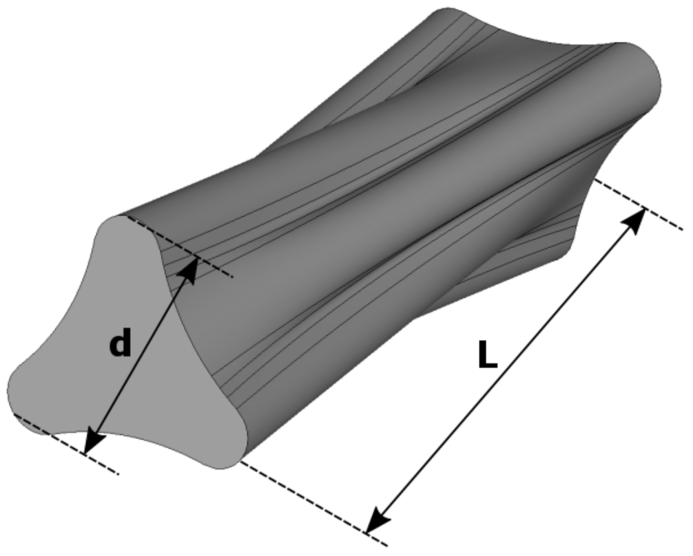
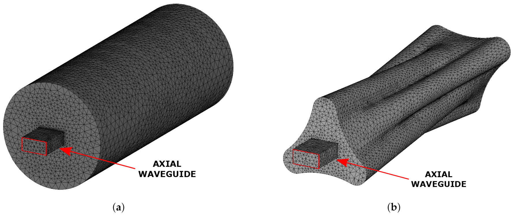
2. Plasma Shaped Cavity and Axial Microwave Injection

In Figure 1, the “plasma-shaped” cavity is shown with its main dimensions. The cavity has diameter d = 48.5 mm and length L = 150 mm, which are typical dimensions for a second generation ECRIS plasma chamber [10]. As said, the cavity’s shape has been obtained by taking into account the electron trajectories as they move under the influence of a minimum-B magnetic field profile which is used for the plasma confinement in ECRISs [11].
As first step of this numerical study, we compare the “plasma-shaped” S-parameters (i. e., the number of modes excited inside the cavity) with those of a standard cylindrical cavity usually employed in ECRISs setups. The adopted cylindrical cavity has a diameter d = 63.5 mm and a length L = 150 mm: these dimensions, comparable with those adopted for the “plasma-shaped” cavity, are the dimensions of the CAESAR Ion Source plasma cavity currently working at the INFN-LNS. Both cavities, initially fed through a standard WR62 axial waveguide, have been simulated with comparable settings: both consist of a vacuum solid with lossy metal boundary conditions ad with the same mesh quality (e.g., curvature tolerance, number of mesh refinement steps). For both cavities, we consider finite conductivity walls with σ = 5.8 × 10 7 S/m. The two geometries with the applied mesh are visible in Figure 2.
The two structures have been analyzed in terms of S-parameters. In particular, the | S 11 | has been evaluated in the frequency range of 14–14.5 GHz. The frequency interval has been selected in order to employ the future “plasma-shaped” cavity with the CAESAR ion source setup. The | S 11 | curve for the two geometries is shown in Figure 3. In the case of cylindrical plasma cavity, very few and bad adapted modes are found inside the chosen frequency range (i.e., not optimal power transfer from the feeding waveguide to the cavity), while, in the case of the “plasma-shaped” cavity, more modes can be found in the same frequency range. In particular, the mode found at the frequency of 14.304 GHz presents a good waveguide-to-cavity coupling ( | S 11 | −15 dB) and the related electric field profile has a maximum around the cavity center, where the plasma usually forms, as seen in Figure 4.
The above configurations, with the same mesh quality, can be simulated in around 20 and 30 min, respectively, with CST Studio Suite on a workstation i7 with 28 cores and 192 GB of ram.

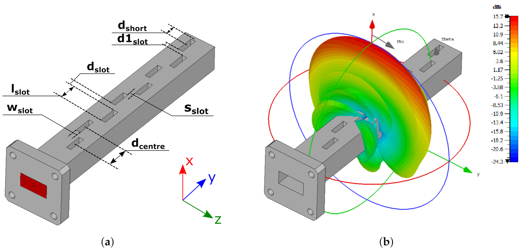
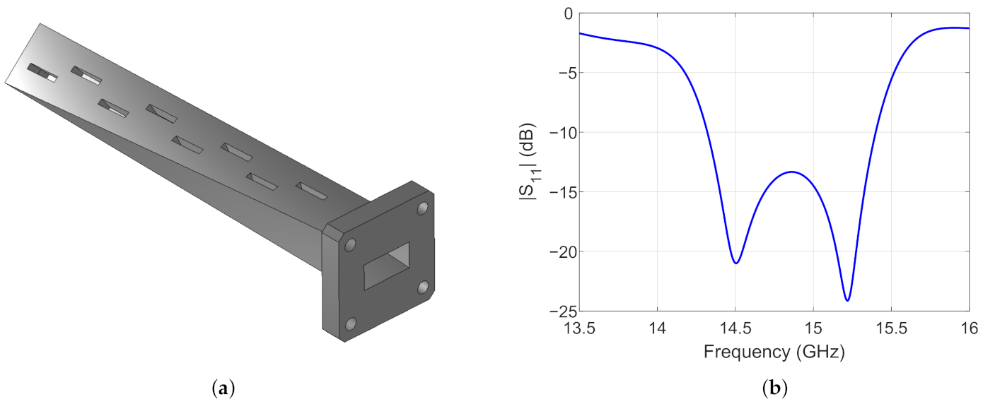
3. Slotted Waveguide Antenna Design

With the aim to improve the microwave-to-cavity coupling and at the same time to have a more uniform and symmetric axial electric field distribution, a radically new microwave injection system has been employed. A slotted waveguide antenna operating in free space has firstly been studied, to explore its behavior as a function of the fundamental project parameters. A first preliminary antenna design is described in Reference [12]. Slotted waveguide antennas find many applications in radar and communication systems due to their low-profile design requirements, mechanical robustness, good efficiency, relative ease of realization and wide operational frequency bandwidth [13,14,15]. The guided wavelength for the TE 10 mode of the rectangular waveguide is given as λ g = c f 1 1 c / ( 2 a f ) , where f is the operational frequency and a is the waveguide large side. The guidelines for the design of a slotted waveguide antenna can be easily found in literature [16,17]. The main design parameters of the simulated slotted waveguide antenna are listed in Table 1. Among these, some critical ones can be highlighted, particularly the width and length of the slots, w s l o t and l s l o t , respectively, and the distance between the last slot center and the closing short wall or d s h o r t . The number of employed slots is also a critical parameter that needs to be taken into account during the antenna project. In fact, the impedance bandwidth is inversely proportional to the slot number. On the contrary, the antenna efficiency increases with the slot number. In general, a trade-off for this parameters is chosen depending on the required performances. The slotted waveguide antenna, shown in Figure 5, has been optimized through the use of CST Studio Suite. The operational bandwidth is 14.2–15.25 GHz with central frequency 14.7 GHz. Eight slots have been employed in order to maximize the | S 11 | impedance bandwidth and at the same time to preserve the radiation efficiency (near 100% in the numerical simulations). The slot number has also been chosen considering the available space along the cavity outer wall, equal to 150 mm. A tuning of the previously reported critical parameters (w s l o t , l s l o t , d s h o r t ) has been performed through a cycle of parametric steps in order to observe their effect on the antenna impedance bandwidth [18]. The calculated | S 11 | curves are shown in Figure 6. After an optimization phase, a good compromise between impedance bandwidth and efficiency has been found by setting w s l o t = 1.75 mm, l s l o t = 9.92 mm and d s h o r t = 6.455 mm.
It is worth to point out that, when the ECRIS is operated at a frequency < 18 GHz, a wide operational bandwidth is desirable in order to employ the frequency tuning effect to boost the source performances in terms of charge states and extracted currents [19]. When the slot number is increased, the antenna directivity increases at the cost of a narrow operational bandwidth: such a characteristic could be an advantage exploitable in the future generation of ECRIS operating at higher frequencies and powered through narrow bandwidth amplifiers.
As a final step, in order to employ the slotted waveguide as microwave launcher for the “plasma-shaped” chamber, a twisted version of the antenna has been created and simulated. The slotted-twisted waveguide antenna is visible in Figure 7a: starting from the WR62 attach flange, a 45-deg twist has been applied to the waveguide body. The structure retains the same project parameters listed in Table 1, except from d s h o r t , in which value has been set to 7.954 mm for optimization reasons. The | S 11 | has been computed and is plotted in Figure 7b, showing that the antenna keeps good performances even with the applied twist.

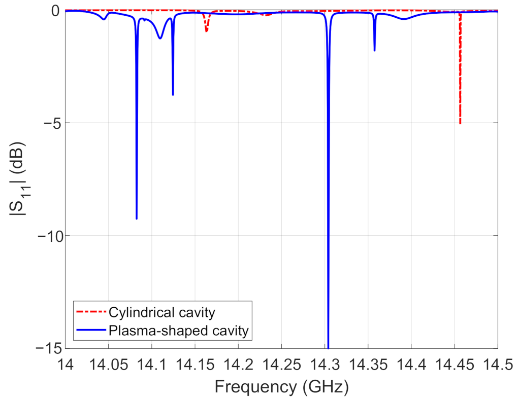
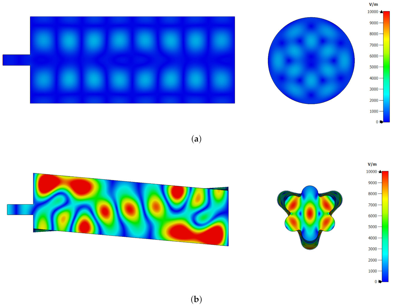
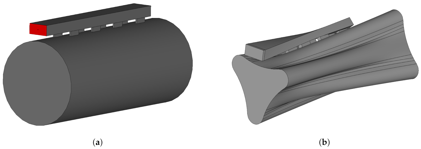
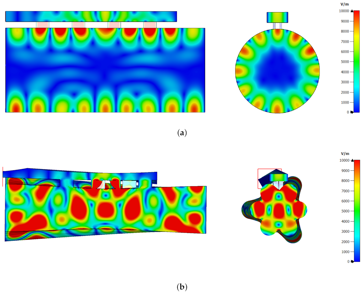
4. Slotted Waveguide Injection Simulations

The previously studied slotted waveguides have been attached to the two plasma cavities in order to obtain the new microwave launch geometry. In the case of the “plasma-shaped” cavity, the slotted waveguide has also been twisted in order to follow the outer wall shape. The two geometries (vacuum volumes) are visible in Figure 8.
The | S 11 | curves have been calculated for both cavities with the new slotted waveguide microwave injection system, as shown in Figure 9. From the plot it can be observed that, using the new microwave injection system, more modes are coupled inside both cavities with respect to the standard axial one. This could be advantageous when one applies the frequency tuning technique in order to improve the ion source performances.
The electric field plot, at the frequency of 14.466 GHz, inside the “plasma-shaped” cavity employing the side-coupled slotted waveguide is shown in Figure 10b. It can be seen that the field presents a maximum around the cavity center and its profile results now symmetric along the cavity axis with respect to the configuration shown in Figure 4 relative of the axial injection system. It is worth noting that, with the same side-coupled slotted waveguide, the cylindrical cavity still presents a predominance of modes with off-axis electric field maxima, as seen in Figure 10a.
The obtained field symmetry leads to a homogeneous power distribution inside the cavity from the multiple radiating slots, with a potential advantage in terms of power absorbed from the plasma. Furthermore, the use of the slotted waveguide could in principle lead to an increase of the total employable power by creating a splitted-injection system composed of multiple slotted waveguides placed radially with respect to the cavity [20].

5. Conclusions and Perspectives

In this work, injection schemes for plasma cavity of ECR ion sources were studied and compared, considering both conventional and innovative plasma chambers. In particular, an advanced antenna for the new chamber shape is studied. This new and groundbreaking antenna and cavity system is twisted so that the cavity volume resembles the electrons trajectories as they move under the influence of the confining magnetic field. The employed shape presents some advantages with respect to a classical cylindrical cavity usually employed in ion source setups. In particular, modes having an electric field profile with maximum near the cavity center, where the plasma usually generates, can be excited. Moreover, the electron-shaped geometry occupies less radial volume, providing more space for the magnetic system axial coils, which turns out to be advantageous for a fine tuning of the plasma-confining magnetic field. Such non-conventional cavity can be coupled to a radically innovative microwave injection. In view of this, a system based on a side-coupled slotted waveguide has been conceived and studied. The slotted waveguide has firstly been analyzed as an antenna operating in free space in order to test its behavior versus the fundamental tuning parameters. Subsequently, the slotted waveguide has been jointed to the two plasma cavity geometries and the two structures behavior has been studied in terms of S-parameters. Numerical results show that the new injection system greatly improves the excited modes inside the frequency band of interest, which could be useful in ion source frequency tuning operations. From the simulation, it has also been found that the use of the “plasma-shaped” cavity in conjunction with the slotted waveguide injection system results in an axially-symmetric field distribution of the excited modes, and this could allow a more uniform power transfer to the plasma from the radiating slots. Furthermore, the use of the side-coupled slotted waveguide also allows more space on the cavity injection flange, employable for other ancillaries.
The plasma-load effect will be predicted by our full-wave numerical tool considering the self-consistent interplay between the microwave field and a fully anisotropic 3D plasma filling the cavity [21,22]. Ongoing simulations already show higher robustness of modal structures established in this kind of cavities.
Finally, experimental characterization of the future slotted waveguide and plasma-shaped cavity prototypes will be performed, in terms of S-parameters and electric field measurements, in order to quantify the performance impact of internal surface roughness derived from the additive manufacturing versus standard realization technique. Preliminary vacuum tests on a pair of 3D metal printed containers samples have already been performed with positive and promising results.

Author Contributions

G.T. and D.M. addressed the conceptualization of the “plasma-shaped” cavity. G.T., O.L., G.S., G.S.M. and D.M. are responsible for the methodology of the study, including analysis and development of the cavity and slotted waveguide microwave injection system. G.S.M., G.T. and O.L. carried out the cavity, antenna and final assembly numerical simulations and optimization. Writing-original draft preparation, G.S.M.; writing-review and editing, G.S.M., G.T., G.S., A.P. and D.M.; supervision and project administration, D.M. All authors have read and agreed to the published version of the manuscript.

Funding

This research received no external funding.

Acknowledgments

The authors wish to thank the 3rd Nat. Comm. of INFN, under the PANDORA_Gr3, for the financial support. Part of this work has been carried out within the Grant73/IRIS project, also supported by INFN (Italian patent pending n. 102020000001756).

Conflicts of Interest

The authors declare no conflict of interest.

References

  1. Mascali, D.; Neri, L.; Gammino, S.; Celona, L.; Ciavola, G.; Gambino, N.; Miracoli, R.; Chikin, S. Plasma ion dynamics and beam formation in electron cyclotron resonance ion sources. Rev. Sci. Instrum. 2010, 81. [Google Scholar] [CrossRef] [PubMed]
  2. Gammino, S.; Ciavola, G.; Celona, L.G.; Mascali, D.; Maimone, F. Numerical simulations of the ECR heating with waves of different frequency in electron cyclotron resonance ion sources. IEEE Trans. Plasma Sci. 2008, 36, 1552–1568. [Google Scholar] [CrossRef]
  3. Koivisto, H.; Ikonen, A.; Kalvas, T.; Kosonen, S.; Kronholm, R.; Marttinen, M.; Tarvainen, O.; Toivanen, V. A new 18 GHz room temperature electron cyclotron resonance ion source for highly charged ion beams. Rev. Sci. Instrum. 2020, 91, 023303. [Google Scholar] [CrossRef] [PubMed]
  4. Hitz, D.; Girard, A.; Melin, G.; Gammino, S.; Ciavola, G.; Celona, L. Results and interpretation of high frequency experiments at 28 GHz in ECR ion sources, future prospects. Rev. Sci. Instrum. 2002, 73, 509–512. [Google Scholar] [CrossRef]
  5. Zhao, H.W.; Sun, L.T.; Guo, J.W.; Lu, W.; Xie, D.Z.; Hitz, D.; Zhang, X.Z.; Yang, Y. Intense highly charged ion beam production and operation with a superconducting electron cyclotron resonance ion source. Phys. Rev. Accel. Beams 2017, 20, 094801. [Google Scholar] [CrossRef] [Green Version]
  6. Xie, D.; Benitez, J.; Lu, W.; Lyneis, C.; Todd, D. Recent production of intense high charge ion beams with VENUS. In Proceedings of the 22nd International Workshop on ECR Ion Sources, Busan, Korea, 28 August 2017; p. THAO01. [Google Scholar] [CrossRef]
  7. Guo, J.W.; Sun, L.; Lu, W.; Zhang, W.H.; Feng, Y.C.; Shen, Z.; Li, L.X.; Li, J.B.; Zhang, X.Z.; Hitz, D.; Zhao, H.W. A new microwave coupling scheme for high intensity highly charged ion beam production by high power 24–28 GHz SECRAL ion source. Rev. Sci. Instrum. 2020, 91, 013322. [Google Scholar] [CrossRef] [PubMed]
  8. Galatà, A.; Mascali, D.; Gallo, C.S.; Torrisi, G. Self-consistent modeling of beam-plasma interaction in the charge breeding optimization process. Rev. Sci. Instrum. 2020, 91, 013506. [Google Scholar] [CrossRef] [PubMed]
  9. Someda, C. Electromagnetic Waves, 2nd ed.; CRC Press: Boca Raton, FL, USA, 2006. [Google Scholar] [CrossRef]
  10. Mascali, D.; Ando’, L.; Castro, G.; Celona, L.; Neri, L.; Gammino, S.; Romano, F.P.; Altana, C.; Caliri, C.; Sorbello, G.; Torrisi, G. Ecr Ion Sources Developments at Infn-Lns for the Production of High Brightness Highly Charged Ion Beams. Proceedings of LINAC2014, Geneva, Switzerland, 31 August–5 September 2014; pp. 254–256. [Google Scholar]
  11. Torrisi, G.; Mascali, D.; Sorbello, G.; Castro, G.; Celona, L.; Galatà, A.; Leonardi, O.; Naselli, E.; Gammino, S. Non-conventional microwave coupling of RF power in ECRIS plasmas. AIP Conf. Proc. 2018, 2011, 020014. [Google Scholar] [CrossRef]
  12. Mauro, G.S.; Torrisi, G.; Leonardi, O.; Galatà, A.; Gallo, C.S.; Sorbello, G.; Mascali, D. Slotted Antenna Waveguide for Microwave Injection in Ion Sources. In Proceedings of the 2020 XXXIIIrd General Assembly and Scientific Symposium of the International Union of Radio Science, Rome, Italy, 29 August–5 September 2020; pp. 1–4. [Google Scholar] [CrossRef]
  13. Werner, F.; Korzec, D.; Engemann, J. Slot antenna 2.45 GHz microwave plasma source. Plasma Sources Sci. Technol. 1994, 3, 473–481. [Google Scholar] [CrossRef]
  14. Woodard, A.; Shojaei, K.; Berrospe-Rodriguez, C.; Nava, G.; Mangolini, L. Electron emission from particles strongly affects the electron energy distribution in dusty plasmas. J. Vac. Sci. Technol. A 2020, 38. [Google Scholar] [CrossRef]
  15. Gatti, R.V.; Sorrentino, R. Slotted waveguide antennas with arbitrary radiation pattern. In Proceedings of the 34th European Microwave Conference, Amsterdam, The Netherlands, 12–14 October 2004; pp. 821–824. [Google Scholar]
  16. Elliott, R.S.; Kurtz, L.A. The design of small slot arrays. IEEE Trans. Antennas Propagat. 1978, 26, 214–219. [Google Scholar] [CrossRef]
  17. Elliott, R.S. The design of traveling wave fed longitudinal shunt slot arrays. IEEE Trans. Antennas Propagat. 1979, 27, 717–720. [Google Scholar] [CrossRef]
  18. Sekretarov, S.S.; Vavriv, D.M. A Wideband Slotted Waveguide Antenna Array for Sar Systems. Prog. Electromagn. Res. M 2010, 11, 165–176. [Google Scholar] [CrossRef] [Green Version]
  19. Celona, L.; Gammino, S.; Ciavola, G.; Maimone, F.; Mascali, D. Microwave to plasma coupling in electron cyclotron resonance and microwave ion sources. Rev. Sci. Instr. 2010, 81, 02A333. [Google Scholar] [CrossRef] [PubMed]
  20. Bernal, S.; Vega, F.; Roman, F.; Valero, A. A high-gain, broad-wall slotted waveguide antenna array to be used as part of a narrowband high power microwaves system. In Proceedings of the 2015 International Conference on Electromagnetics in Advanced Applications (ICEAA), Turin, Italy, 7–11 September 2015; pp. 618–621. [Google Scholar]
  21. Mascali, D.; Torrisi, G.; Neri, L.; Sorbello, G.; Castro, G.; Celona, L.; Gammino, S. 3D-full wave and kinetics numerical modelling of electron cyclotron resonance ion sources plasma: steps towards self-consistency. Eur. Phys. J. D 2015, 69, 27. [Google Scholar] [CrossRef]
  22. Torrisi, G.; Mascali, D.; Sorbello, G.; Neri, L.; Celona, L.; Castro, G.; Isernia, T.; Gammino, S. Full-wave FEM simulations of electromagnetic waves in strongly magnetized non-homogeneous plasma. J. Electromagn. Waves Appl. 2014, 28, 1085–1099. [Google Scholar] [CrossRef]
Figure 1. “Plasma-shaped” cavity with its main dimensions: diameter d and length L.
Telecom 02 00004 g001
Figure 2. (a) Standard cylindrical cavity and (b) “plasma-shaped” cavity models. Applied mesh and axial feeding waveguides are visible.
Telecom 02 00004 g002
Figure 3. | S 11 | curve, inside the operational bandwidth of 14–14.5 GHz, for the standard cylindrical cavity and the “plasma-shaped” one.
Telecom 02 00004 g003
Figure 4. Electric field module plot on side and front slices for: (a) cylindrical cavity ( f 0 = 14.457 GHz) and (b) “plasma-shaped” cavity ( f 0 = 14.304 GHz). Electric field has been normalized to the maximum value of 10 kV/m.
Telecom 02 00004 g004
Figure 5. (a) Slotted waveguide antenna model with fundamental design parameters highlighted. The structure consists of a steel block (grey object) fed through a waveguide port, highlighted in red. (b) Farfield pattern of the presented slotted waveguide antenna.
Telecom 02 00004 g005
Figure 6. | S 11 | versus (a) w s l o t , (b) l s l o t and (c) d s h o r t . For each parameter variation, the remaining ones have been fixed to the nominal design values reported in Table 1.
Telecom 02 00004 g006
Figure 7. (a) Slotted-twisted waveguide antenna and (b) computed | S 11 | . The antenna retains the design values reported in Table 1 except for d s h o r t , now equal to 7.954 mm.
Telecom 02 00004 g007
Figure 8. Slotted waveguide injection system coupled to: (a) standard cylindrical and (b) “plasma-shaped” cavities. Simulations have been made by using vacuum volumes.
Telecom 02 00004 g008
Figure 9. | S 11 | curve, for the standard cylindrical cavity and the “plasma-shaped” one with the slotted waveguide microwave injection system, inside the operational bandwidth of 14–14.5 GHz.
Telecom 02 00004 g009
Figure 10. Electric field module plot on side and front slices for: (a) cylindrical cavity ( f 0 = 14.388 GHz) and (b) “plasma-shaped” cavity ( f 0 = 14.466 GHz) employing the side-coupled slotted waveguide injection system. Electric field has been normalized to the maximum value of 10 kV/m.
Telecom 02 00004 g010
Table 1. Slotted waveguide antenna main design parameters.
ParameterValue [mm]Description
l s l o t 9.92Slot length
w s l o t 1.75Slot width
d c e n t e r 13.45Slot centers distances
d s l o t 3.53Longitudinal distance between slots
d1 s l o t 2.53Last two slots distance
s s l o t 2.75Transversal distance between slots
d s h o r t 6.455Last slot center to short wall distance
Publisher’s Note: MDPI stays neutral with regard to jurisdictional claims in published maps and institutional affiliations.

