BIM Interoperability Analyses in Structure Design


Department of Civil Engineering, University of Lisbon, Av. Rovisco Pais, 1049-001 Lisbon, Portugal
*
Author to whom correspondence should be addressed.
CivilEng 2021, 2(1), 174-192; https://0-doi-org.brum.beds.ac.uk/10.3390/civileng2010010
Submission received: 2 December 2020
/
Revised: 5 February 2021
/
Accepted: 6 February 2021
/
Published: 14 February 2021
(This article belongs to the Special Issue Advances in Civil Engineering)
Abstract
:The building information modelling (BIM) methodology supports collaborative works, based on the centralization of all information in a federated BIM model and on an efficient level of interoperability between BIM-based platforms. Concerning the structure design, the interoperability capacity of the most used software presents limitations that must be identified and alternative solutions must be proposed. This study analyzes the process of transfer of structure models between modeling and structure analysis tools. Distinct building cases were performed in order to recognize the type of limitations verified in the transfer processes concerning two-way data flow between several software. The study involves the modeling software ArchiCAD 2020, Revit 2020, and AECOsim 2019 and the structure analyzes tools SAP 2020, Robot 2020, and ETABS 22020. The transfer processes are realized in two ways: using the native data format; using a universal standard data transfer, the Industry Foundation Classes (IFC) format. The level of maturity of BIM in structure design is still relatively low, caused essentially by interoperability problems, but despite the limitations detected, this study shows throughout the development of several building case, that the methodology has clear advantages in the development of the structure project.
1. Introduction
The technological evolution applied to the construction sector has been introducing potential in the speeding up of the development of multi projects concerning a building, in the monitoring of the construction work and, later, in the management of the building. In the 60s of the 20th century, computer-aided design (CAD) emerged, taking the paper project drawings to the computer screen, facilitating the execution of the graphic documentation of the project and the transferring of digital drawings among the design team. However, despite the recognized support of CAD systems, they do not guarantee a complete efficiency in the coherence between the different technical drawings that are associated with a building project [1]. However, the necessity of an efficient collaboration between the various experts involved in the development of a project, requires an agile interaction of communication and a guaranty of the correct transmission of data between phases, but the traditional support based on paper or even digital drawings can bring some inaccuracies [2].
The conceptual idea of creating a digital model that allows to concentrate the information related to the development of a complete project was initially mentioned by Eastman [3] in the 1970s, having the term building information modelling (BIM), began to be applied in 1987, when the first commercial BIM product, the ArchiCAD, was launched. The BIM methodology, currently supported on advanced technology, admits the ability to visualize a representative three-dimensional (3D) model of the building, and the centralization of all the information associated with the building project [4]. The BIM model is developed on a base of multitask collaboration between all stakeholders and expertise that contributes to the project fullness [5].
Despite the benefits that have been recognized in relation to BIM implementation in the construction industry, its adoption within the companies and project offices, have been imposing significant organizational challenges related to the internal cultural adaptation concerning work modes, data transfer processes between phases and communication with partners [6]. Also, a relevant initial investment in technology and training is required. Although the available BIM support technology admits a fairly integrated approach to the digital representation of all building disciplines there are still gaps that the researchers intend to overcome [7]. The most recent studies points in two main directions [8]:
- Software houses have been admitting an incremental capability of integrating functionalities, referred to as extensions, add-in, and plug-in, based on the native format of the main system;
- The international organization BuildingSMART, which brings together enterprises and professionals of the construction industry from several countries, is responsible for issuing the standard data format, the Industry Foundation Classes (IFC) [9], and has been lunching new versions with increasing efficiency.
However, it is required of the engineer when using BIM-based platforms on the development of structure project, to recognize the limitations on interoperability that is still associated with the systems, essentially focused on the two-way data flow processes that take place between the modeling and structure tools. This report analyzes two research perspectives [10]:
- Transfer of models performed on the basis of the native format of data;
- Transfer based on IFC format.
The text describes the main phases required in the development of BIM structure design, with the objective of verify the quality of the data when models are transferred between modelling and structure analysis tools.
The most recent reports concerning the adopting of BIM within structural engineering and design points essentially to collaboration, interoperability, and level of development (LOD). The review bibliographic work of Vilutiene et al. [11] demonstrates “that research on BIM applications for structural engineering has been constantly growing with a sudden increase after 2014,” but “the number of studies on structural engineering and BIM is still quite low” when compared with other areas of BIM application. However they found that the most recent topics concerning structures, are related with interoperability, data handling, simulation, automation, cost benefit analyses, and model view definition. Following Shin [12] the quality of structures depends on the efficiency of a collaborative work based on a high level of interoperability that can be achieved using an Open BIM platform and the definition of models reaching LOD 300. Supporting this idea Subramani & Ammai, [13] used Primavera, a BIM technology platform, to allows BIM data exchange and the integration of distinct participants from building proprietor to architects and engineers on the development of structural projects, allowing an adequate communication among the assignment group. Within the Primavera BIM platform, “several activities that included teams engaged in are enhancing, extracting, taking part, updating, and placing other applicable facts to the built version database.” In addition Musella et al. [14] revels a BIM perspective concerning the managing of structural information after a seismic event occurred in a building, pointing strategies “to mitigate the catastrophic effects of earthquakes on the occupants of a building, as well as improve the management of the emergency that inevitably ensues.” In the study the authors also use openBIM platform based on the standard data format Industry Foundation Classes (IFC), in order to organize all the information, existed, produced, and changed because of the earthquake. As so, both the interoperability ability of the tools available and the type and quantity of information assigned to a BIM model, are the most relevant aspects to be explored, analyzed, and discussed concerning structural engineering in BIM, currently and in the next future. The present study intends to contribute in a positive way to a better knowledge of how to use BIM platforms in the structural sector.
As a methodology, a first modeling process is presented using distinct tools operating over building of different size and complexity. The second step considers the application of loads, choosing the best tool to operate this task, the modelling or the structural software. The next step is related to the structural analyses itself, but focused on the accuracy of the model transferred between software. Finally the reinforcement details is performed in the structural tool and after this information is incorporated in the initial model, in order to follow the main concept of BIM, that is the centralization of all the information in just a federated BIM model. The main objective of the application of this methodology is to characterize the most adequate strategy of work in a structural design.
2. Structure Models
On the development of a BIM structure project, the engineer proposes, adjusts, and rectifies an adequate structure solution in the form of a virtual model composed of parametric objects [15]. In this process, frequent users of AutoCAD (Autodesk) admit that handling with Revit (Autodesk) system is quite easy, as it presents similar interfaces. However, many other software houses have settled new BIM-based tools, following the technological evolution required by the competitive market, namely AECOsim (Bentley) and ArchiCAD (Graphisoft). In order to compare the performance of each of these BIM-based tools, they were applied in distinct building cases.
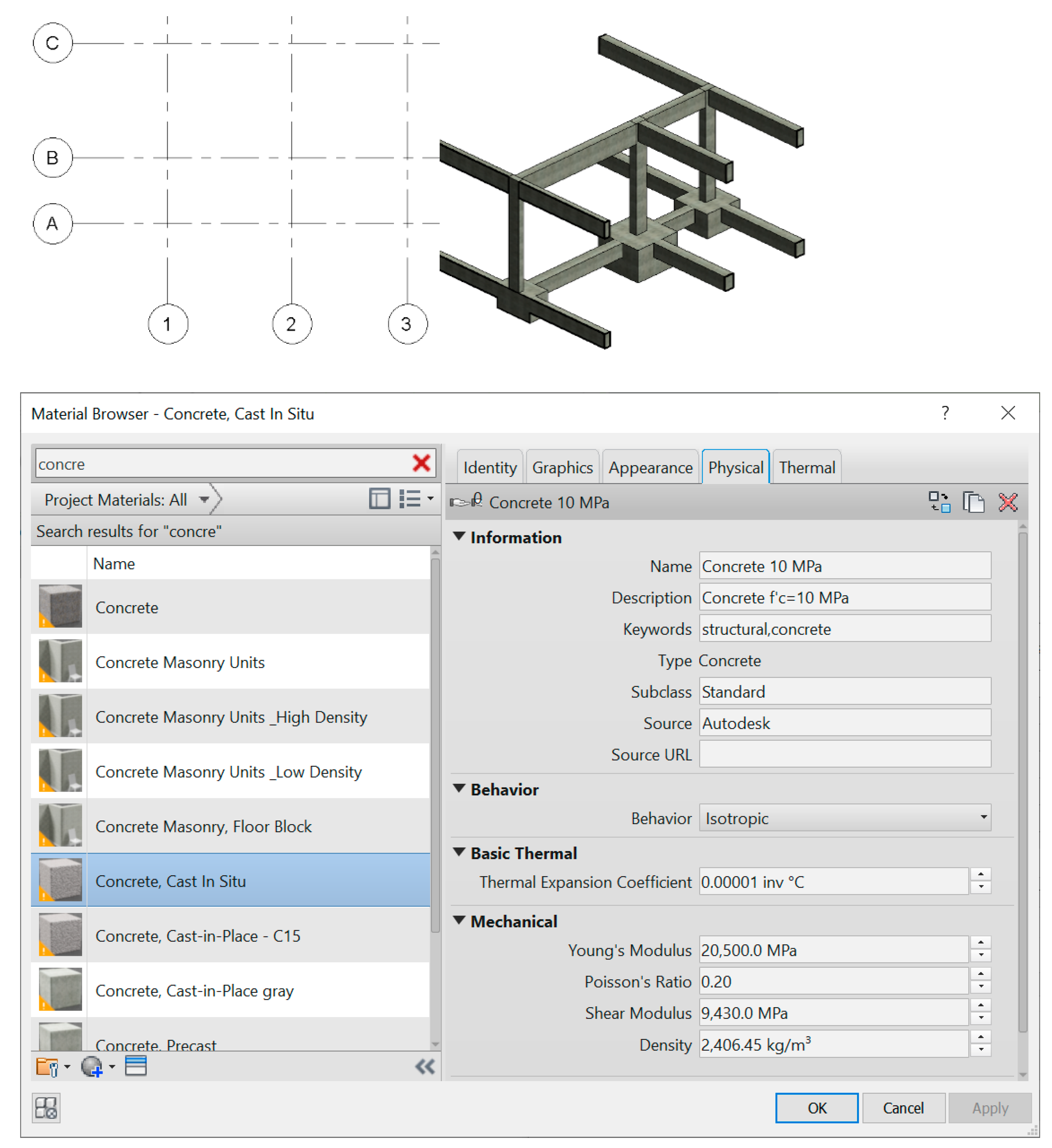
All modelling BIM tools work with parametric objects. The modeling process starts with the identification of orthogonal alignments referred to a plant view and the levels of the floors considered in each building. Next, the parametric objects required to represent the building are chosen from the library of objects available in the system. Concerning the structure model, the selected objects belongs to structure families, namely, columns, beams, walls, slabs, and foundations (Figure 1).
The objects are selected from the library and adapted in order to represent with accuracy all the structure components that composed the established solution for each building case. Not just the geometry is represented but also the material to be applied and the respective physical proprieties. As, for all considered building cases, a reinforced concrete solution was established, the materials assigned to each structure component are concrete and steel, and the values of the associated mechanical properties, namely the modulus of elasticity, the Poisson coefficient, and the unit volume weight, were adjusted to the real ones to be applied in the buildings structure (Figure 1).
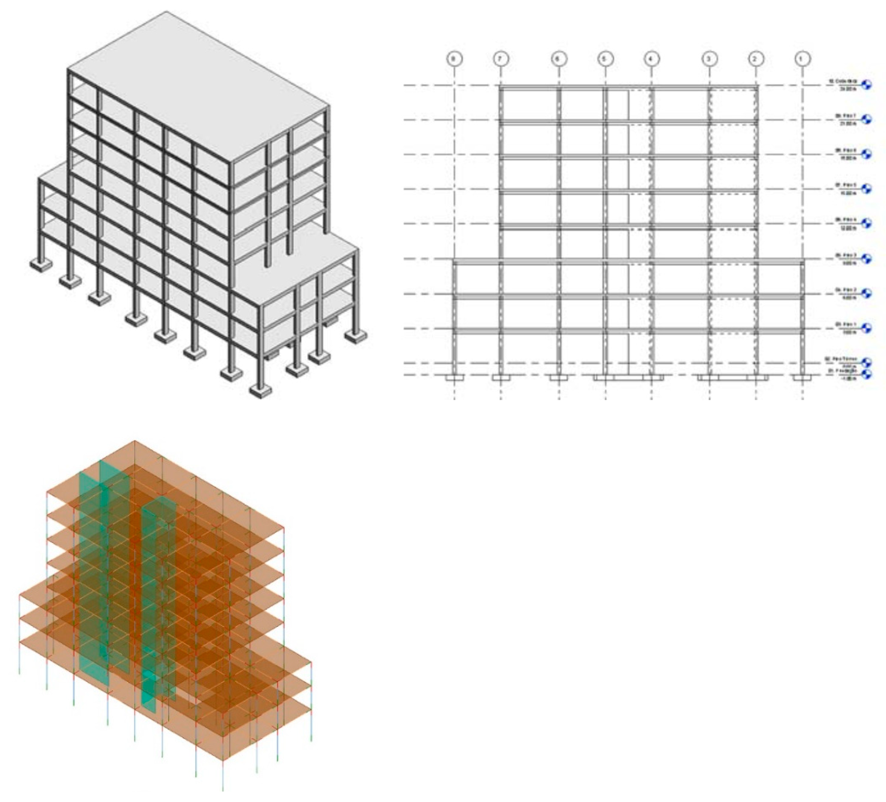
- The first building case is composed of eight elevated floors, located in Lisbon. The structure frame is a concrete beamed solution, and presents a regular distribution of their elements, both in plant and in elevation [16]. The BIM model is generated in Revit using the parametric objects available on the structure library. A physical model is then created, however, as all elements are classified as structure objects, the modelling system incorporates the discretization functionality, allowing the user to visualize the respective analytical model, composed of all components idealized as finite elements. Each of these elements is represented by its axis (beams and columns) or by its middle surface (slabs or walls), and they are associated to the correspondent’s physical properties, that are later required in the structure analyses process, namely, cross-section areas and inertias. Looking at the analytical model, the engineer must verify the consistency of all connections prior to its export to the structure analysis system (Figure 2).
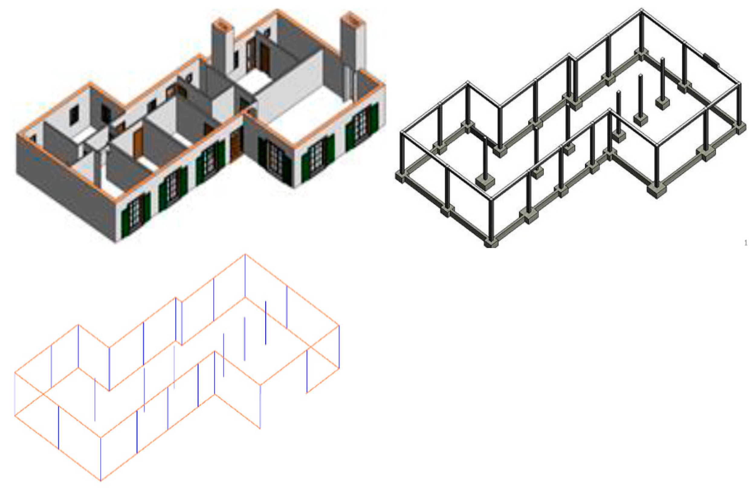
- The second case is a single-family house. The building, located in Santarem, Portugal, is formed of a ground floor. Using the Revit tool, the architecture and structure components of the required BIM model were generated. The structure solution was defined over the architecture design, allowing the engineer to judge the suitability of the structure considering the architecture constraints (Figure 3). The structure solution is composed of a concrete fungiform slab with peripheral beams, a set of internal columns, and a foundation system composed with a linear beam-foundation positioned on the border and individual supports. The analytical model was also performed and the consistency of each node is verified [16].
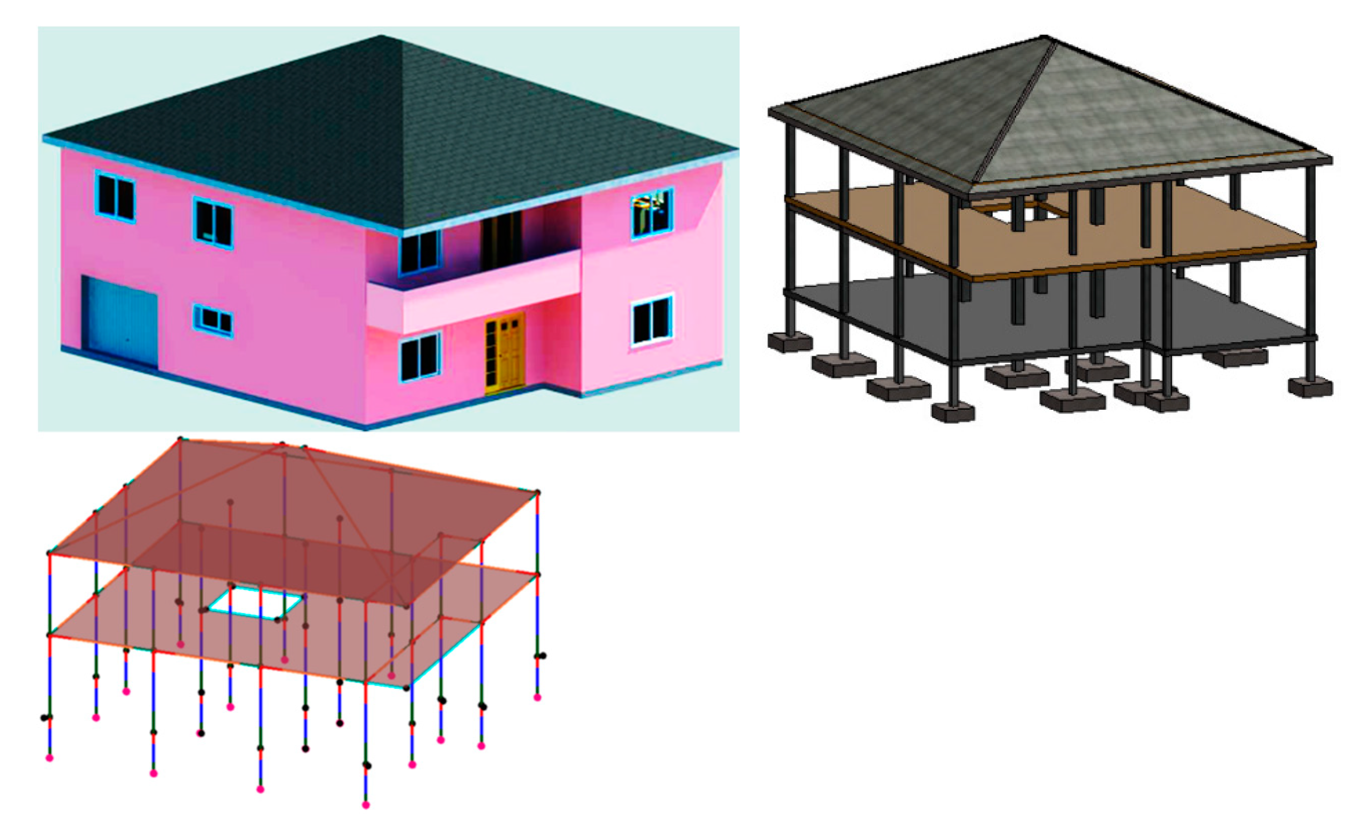
- A two-floor house located in the north of Portugal was analyzed. Using also the Revit system, the components of architecture and structures of the BIM model were generated. The structure frame was considered over the architecture component in order to fulfil all architectural requirements. The structure solution is composed of fungiform slabs, with beams positioned in the boarder at the ground and elevated floors, a foundation system formed with isolated elements and concrete reinforced slabs supporting a pitched roof (Figure 4). An analytical model was also obtained and each connection between elements was checked [17].
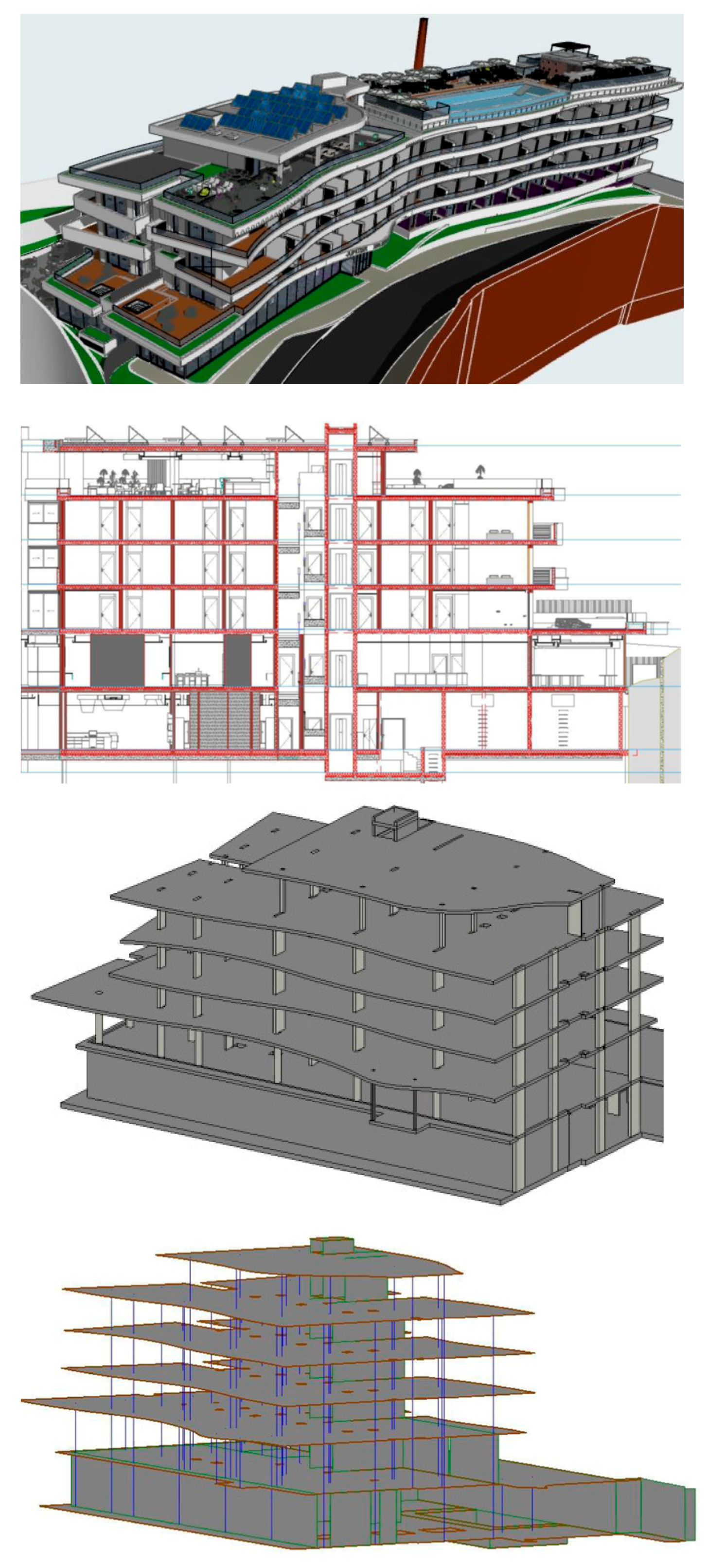
- A hotel building was also considered. The building is located in Algarve, on the south of Portugal, and both architecture and structure components of the BIM model were created using the ArchiCAD system (Graphisoft) [18]. The established structure solution considers concrete fungiform slabs, in order to properly accommodate the networks of hydraulic and air conditioning systems, and to satisfy the organic configuration considered in the architecture design. In addition, isolated columns were placed and, in the periphery of the ground floor, a resistant wall is positioned (Figure 5). The required parametric objects representing structure component were all selected from the BIM system library. This tool also allows the representation of the correspondent analytical model.
- A technical building of a dam was modeled. The AECOsim Building Designer (Bentley) system was used to generate the structure BIM component, based on dwg drawings of the project made available. The parametric elements, related to reinforced concrete elements, were selected from the tool’s library and adapted according to the established solution (Figure 6) [19]. The system also admits the representation of the analytical model, discretizing the beams and columns through frames of linear elements, and the slabs and walls through shell elements, allowing the engineer to check the consistency of all the connections between elements.
However, none of the mentioned systems, used to model each building structure, incorporates structure analyses capacities. Thus, to pursue the analysis process it is necessary to transpose each structure model into a calculation software.
3. Structure Analyses
The created structure models were all transferred into an analytical structure software in order to obtain diagrams of efforts and deformations and to determine the areas of reinforced bars to be included in each structure element (beams, columns, slabs, walls, and foundations). Several structure systems of distinct software houses were tested, namely, SAP (CSI) [17,19], Robot (Autodesk) [16], and ETABS (CSI) [18].
A comparative study concerning the identification of the principal limitations associated to the process of export of models between tools was then carried out. To accomplish that, the geometric consistency of the transferred model is verified, and some adjustments were made. Then, the required loads and the mandatory loads combinations, related to the ultimate limit state (ULS) and service limit state (SLS), were considered and the structure analyses were then performed. The efforts and deformations obtained as a result allows to determine the necessary quantity of reinforcement in each structure component. Finally, using the functionalities available in the systems, the detail drawings of bars were produced. This sequence of operations was meticulously verified, with a particular attention to the level of quality of the information transferred in each task.
3.1. Models Export
In order to perform the necessary change in data process between software, two options were considered: native data format is used when the models are transfer between software belonging to the same company; data transfer based on the IFC format is used when the systems belongs to distinct software houses. The assessment of the level of the existing interoperability capacity is analyzed:
- Revit/Robot export. The model created in Revit is transferred to the Robot software, and the quality of the transferred data is analyzed. The geometry and physical properties of most structure elements have been correctly recognized by the calculation system. However, over the model it was necessary to make some adjustments; the stair elements were not recognized by the system and then sloped slabs were modelled instead, and the foundation elements were not transferred and the correspondent supports were redefined (Figure 7). As both systems, Robot and Revit belong to Autodesk, a high level of interoperability is verified, although not entirely error-free [16].
- Revit/SAP transfer. The process of exporting a Revit model to SAP structure analysis software is made based on the use of a plug-in, named CSIXRevit. After the model is transferred to SAP, the consistency of the model is verified. Most of the structure elements were well transferred, namely, foundations, columns, walls, beams, and slabs, but the stairs and foundations were not. The material, concrete C30/37 and steel A500 NR SD, and the associated mechanical properties were also properly accepted (Figure 8). However, it was necessary to make some corrections over the analytical model, in particular, the axis of linear finite elements and the rigid links established previously on Revit tool, were not well identified by the SAP system [17].
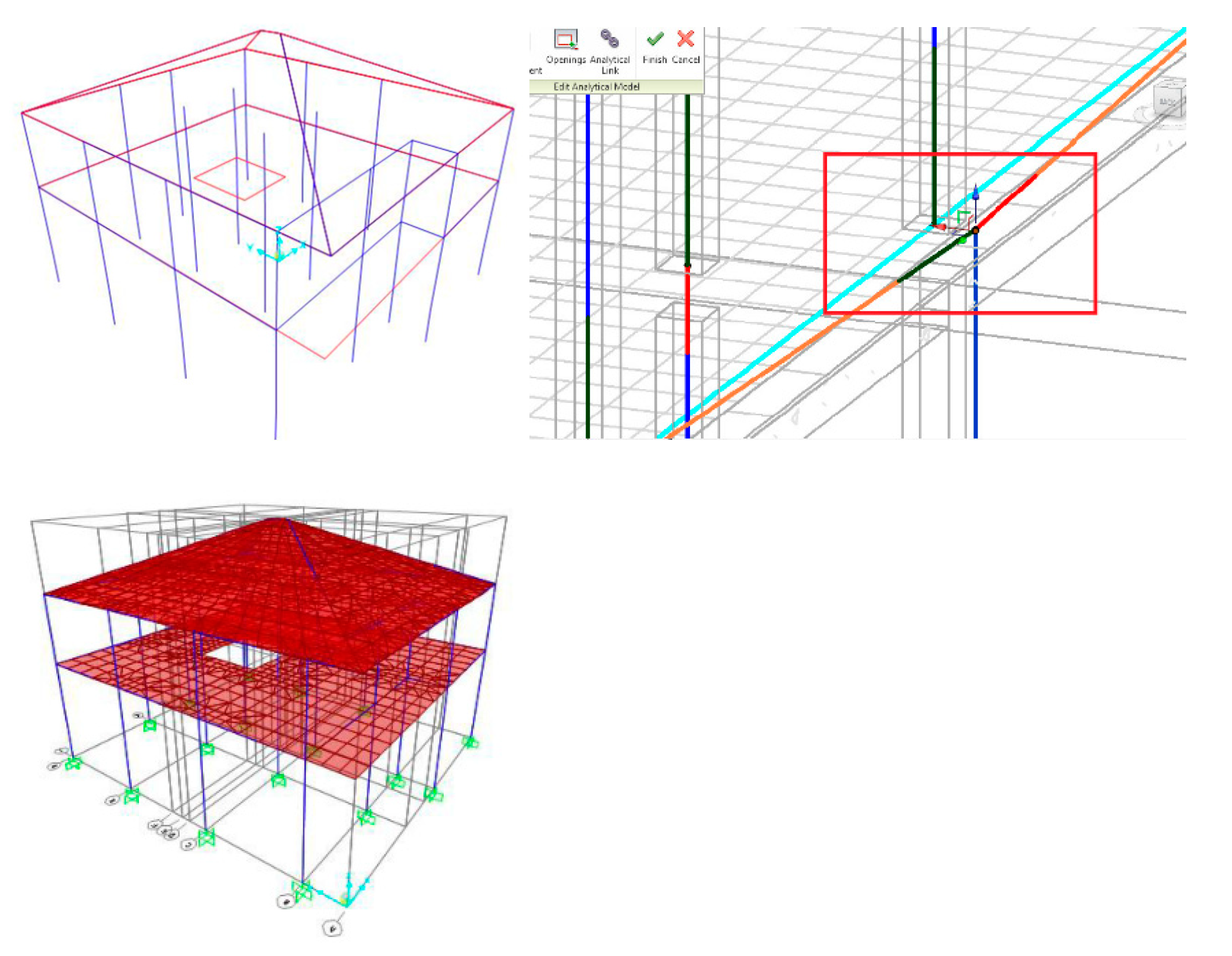
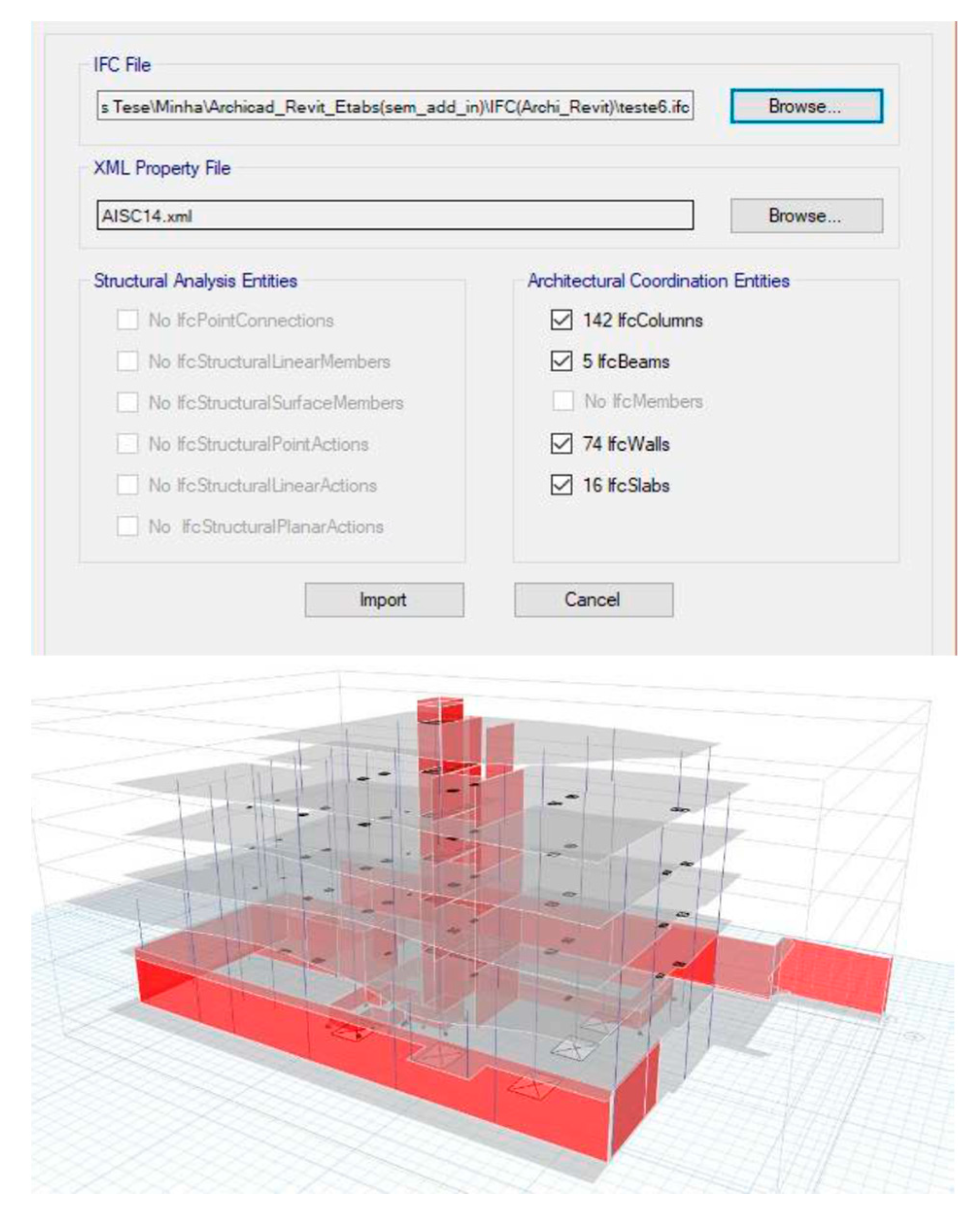
- ArchiCAD/ETABS export. The model created in ArchiCAD was saved in the system using the IFC data standard, in order to allow its transfer to ETABS (CSI) system. Although, previously at ArchiCAD all ifc elements (IfcColumns, IfcWalls, and IfcSlabs) were specifically selected to be transferred, a careful geometric analysis carried out over the transferred model identifies some inconsistency errors (Figure 9). A large number of adjacent elements were disconnected, requiring a relevant volume of adjustments. This additional work is time consuming, but a correct analytical structure model must be obtained to guarantee correct result [18].
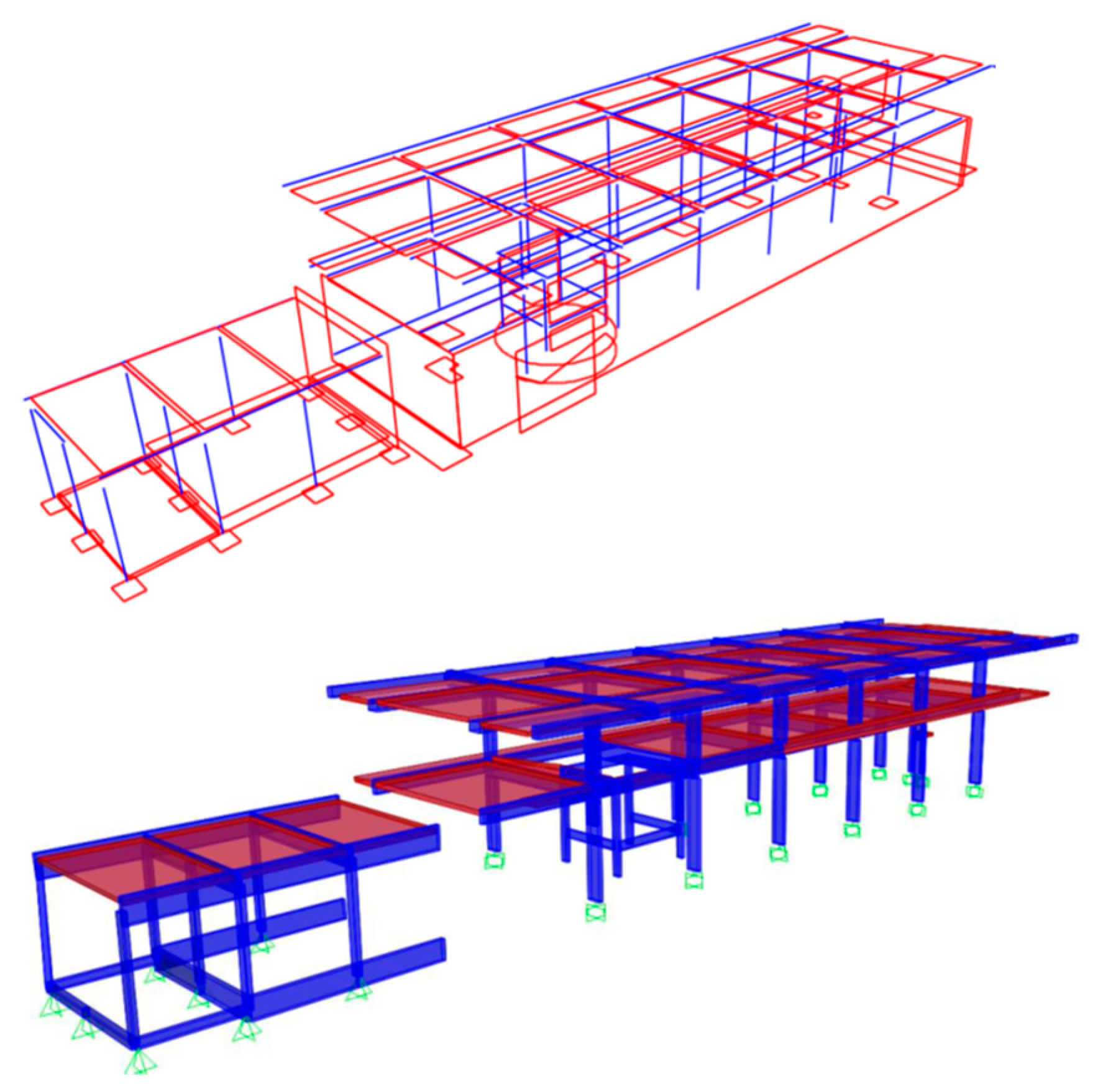
- AECOsim/SAP transfer. The model created in AECOsim is saved in IFC format and transferred to SAP. This system identifies some of the ifc elements transferred, namely, ifcStructurePointConnection, ifcBeam, ifcColumn, ifcSlab, ifcStructureCurveMember, and ifcStructureSurfaceMember; but not being recognized foundations, stairs, border conditions, and loads. However, the cross-sections and thicknesses of each element are correctly transferred (Figure 10). The SAP merge joints functionality, allows to join nodes that have a minimum distance between axis ends, but does not check the orthogonality of the resultant adjustments, leading to incorrect situations. The interoperability between the two systems is still limited, however, the possibility of exporting the analytical model from the parametric model is easily performed, contributing to speed all process and to increase productivity [19].
3.2. Analyses Process and Reinforcements
The next step is to perform the structure analyses based on the current applicable Eurocodes. The structure elements are represented as linear finite elements (beams and columns) or as finite element mesh surface (slabs and walls). The mechanical characteristics associated to each structure elements are those that result from their geometry and physical proprieties of the materials. All structure analyses software allows the application of loads, including the seismic action. Thus all loads and the mandatory load combinations were applied over consistent structure models:
- The death loads relating to the structure own weight (PP) is automatically assumed based on the unit weight of the reinforced concrete;
- The permanent loads (PC) are related to the distinct coating applied according to the type of use per zone of each floor, and with the interior walls applied as distributed weight;
- The variable load (SC) considers the type of use in each floor;
- The seismic action (SISM) is quantified according to the medium spectral response of the building and the seismicity coefficient associated to the house location.
To obtain the deformations of the structure two combinations of actions were considered:
1PP + 1CP and 1PP + 1CP + 0.4SC
To determine the efforts in the structure, three load combinations were applied:
1.35PP + 1.35CP + 1.5SC, 1PP + 1CP + 0.4SC + 1.5SISM1 and 1PP + 1CP + 0.4SC + 1.5SISM2
The structure analyses results are presented in the form of diagrams and 3D models of deformations and stresses, as well as notes and reports. The analyses results allow to establish, for each structure element, the cross-section area of reinforcement bars needed. Then, each system defines automatically the respective bar detailing the drawings required as graphical documents of a structure project:
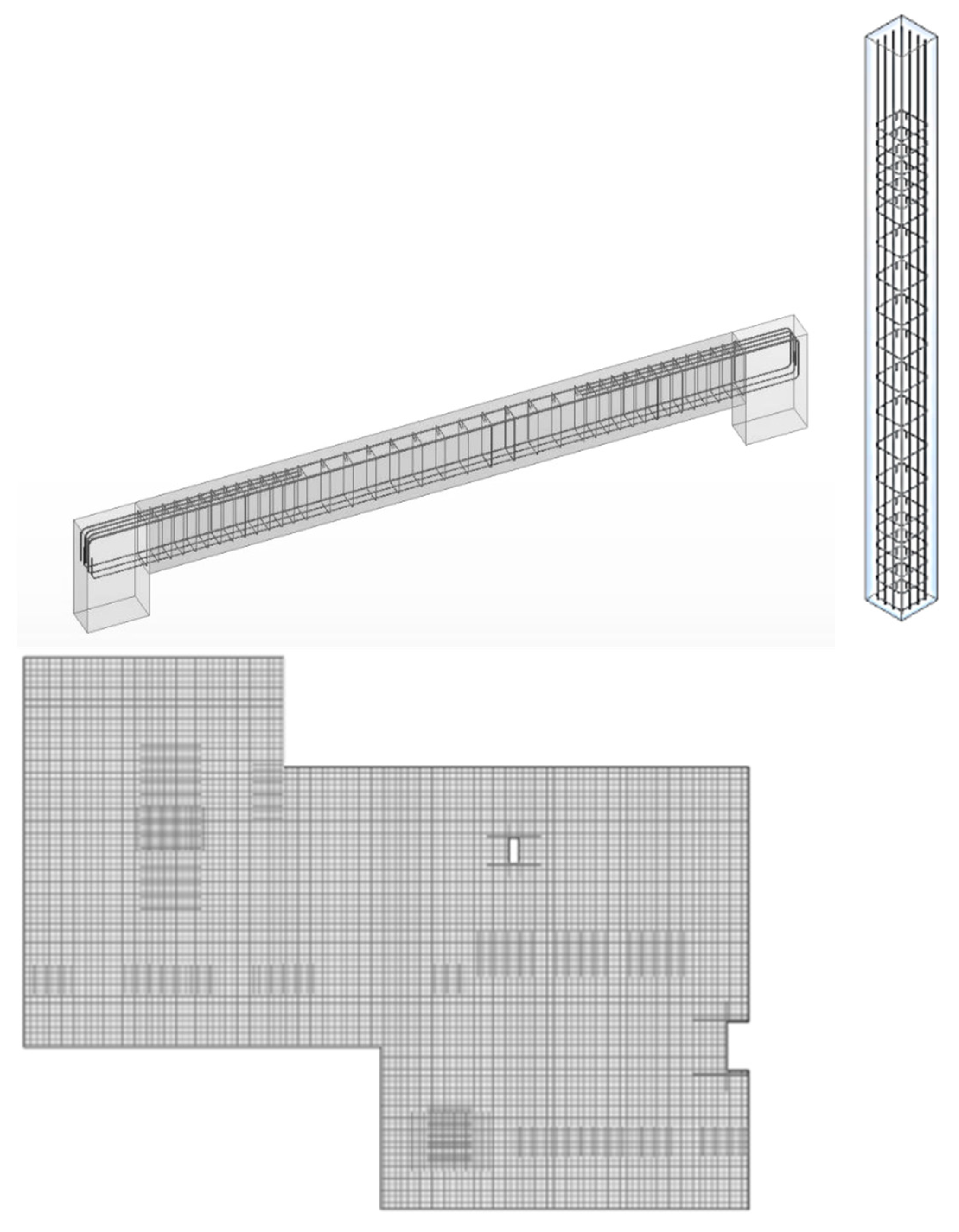
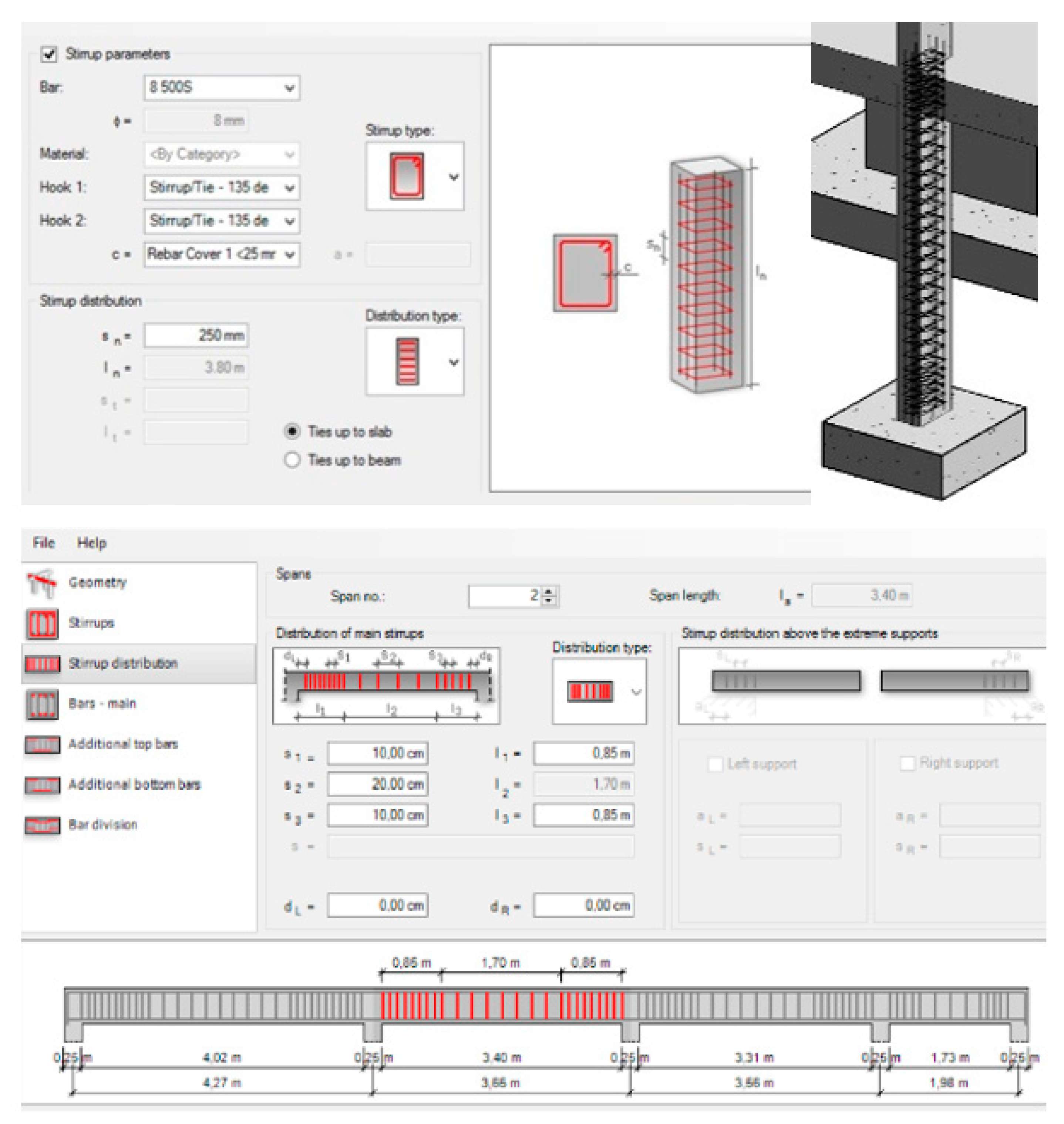
- Robot. To proceed with the analyses, each slab is discretized in finite element mesh surfaces and after calculation, the system automatically set the value of the reinforcement required for each finite element based on the materials and cover applied. For the resistant safety verification of columns, the normal stresses is considered and the detailing of the necessary reinforcement is conducted in an automatic way, based on the spacing between the stirrups and the number of longitudinal bars to be allocated per side. The verification of beams resistance is based on the evaluation of the stresses considering the envelope of the distinct applied loads combinations. Concerning the foundations elements, the system only allows to check the forces acting in the supporting nodes and the user must perform a safety check, based on traditional computational methods (Figure 11).
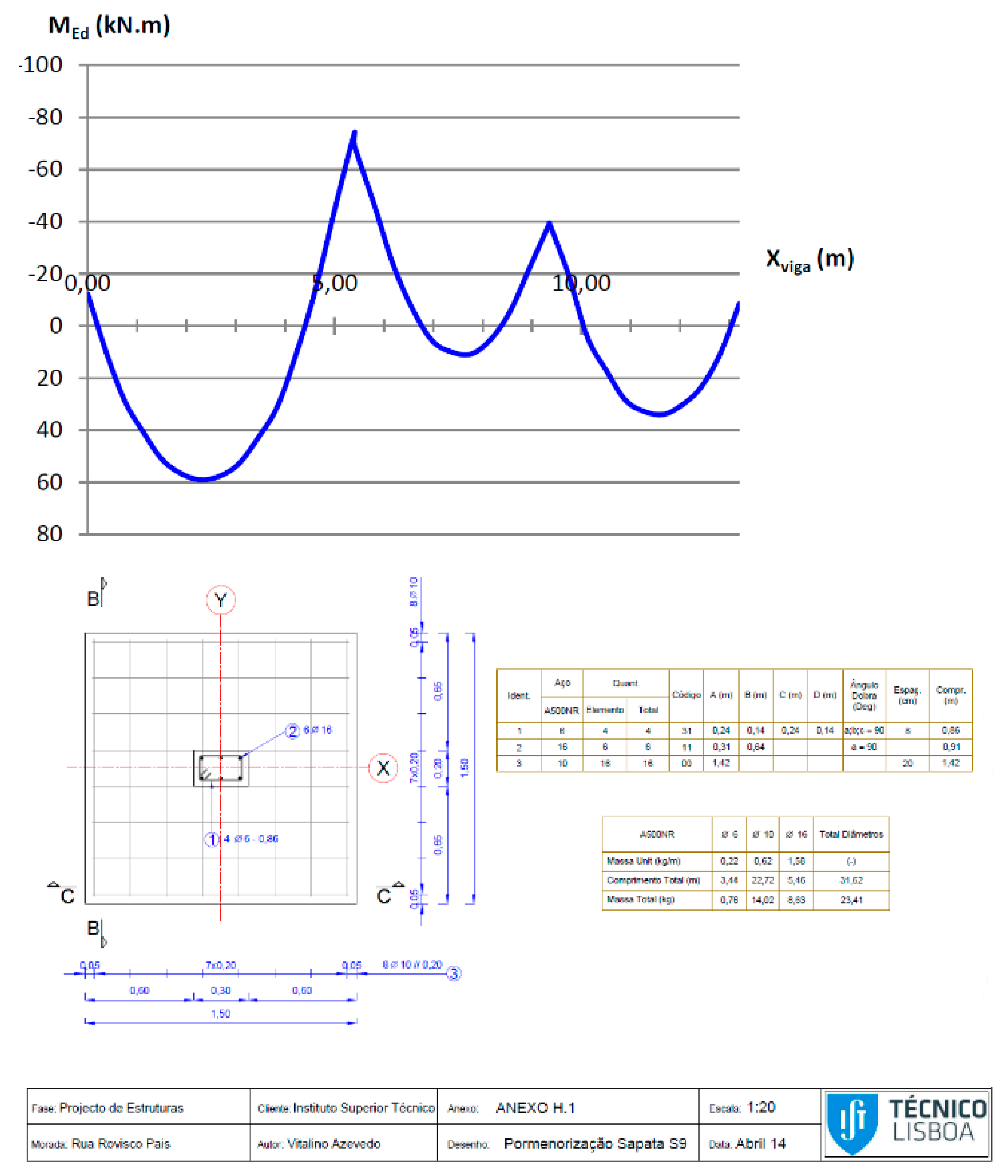
- SAP—Checked the consistency of the imported model, SAP system performs the structure analyses according to the current Eurocode. Based on the diagrams of the analyses results the required quantity of steel is determined and the concrete reinforcement detailing drawings of all elements are generated (Figure 12).
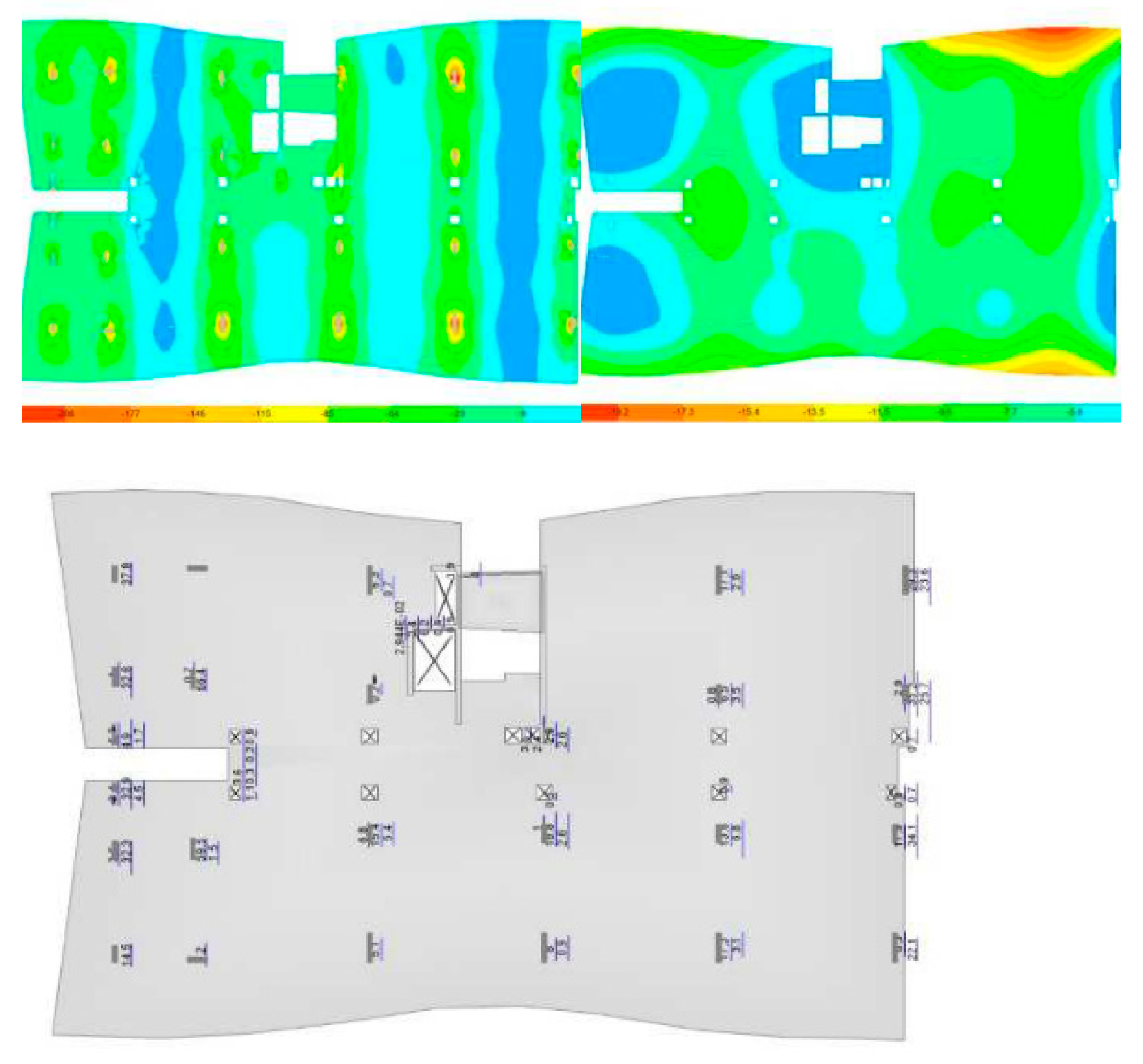
- ETABS—The design of slabs, columns, and beams is carried out in accordance with the current Eurocodes. The system determines stresses and deformations visualized in diagrams and 3D models. Then, the tool is able to determine the necessary reinforcement bars for each structure element and automatically proceeds with the elaboration of the detailing drawings (Figure 13).
3.3. Data Centralization
However, according to the basic concept of the BIM methodology, the elaboration all disciplines and tasks related with a project should be centralized in a federated digital BIM model and it must include all the information generated along the design process. As so the structure analyses performed in each building case should be transferred to the initial structure BIM model, updating its database which should be accessible to all professionals for further retrieving and reuse. This concerns a reverse transfer process of the models, from the structure analyses tool into the BIM modeling system. However, this process presents a much higher volume of inaccuracies, and that is a reason often pointed out to justify the resistance of the implementation of BIM in the design of structures:
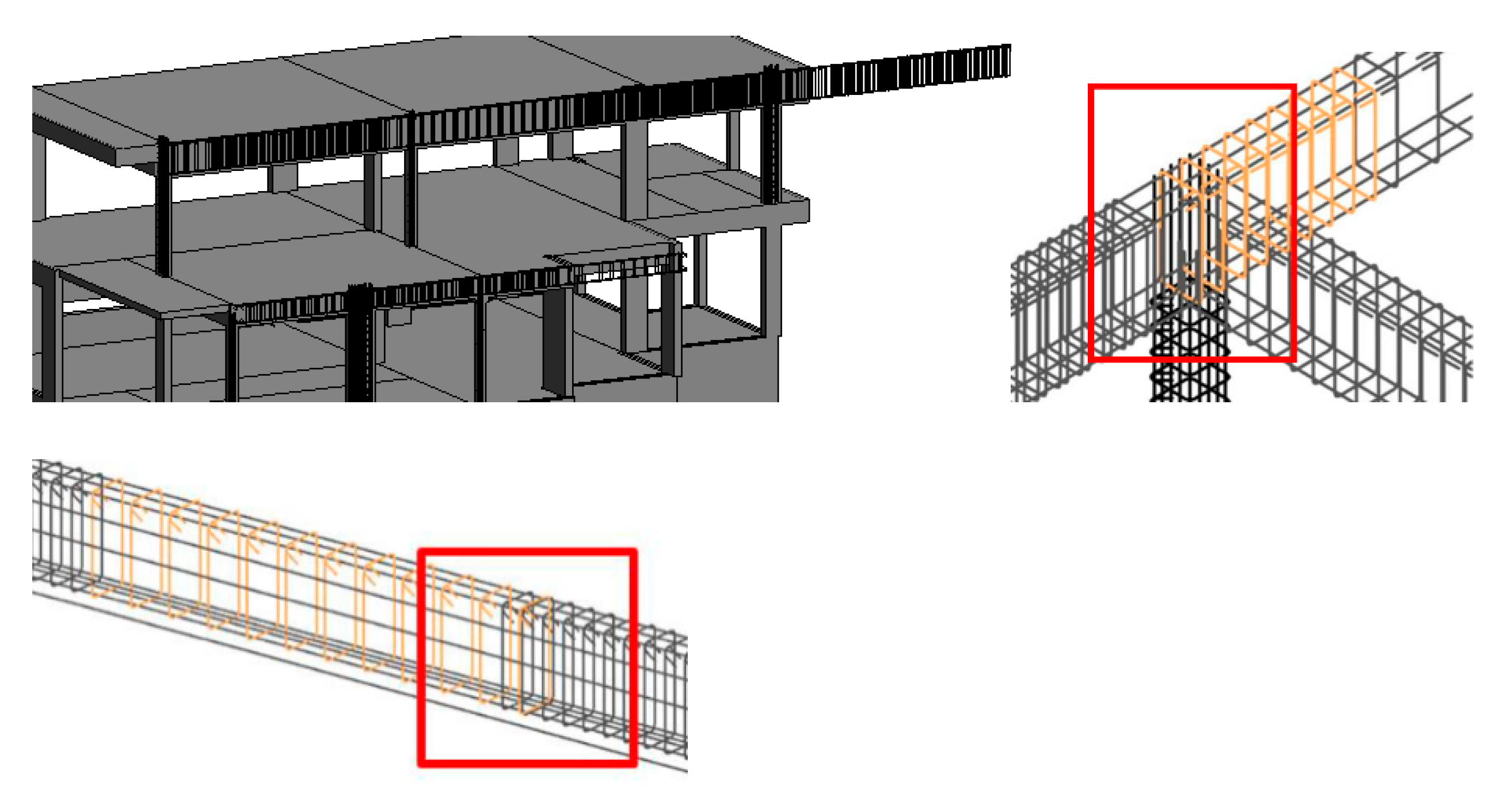
- Robot/Revit export. The reinforcements can be detailed in Robot and then transferred into the Revit model, or only the required areas for each element is transferred, and the bars distribution is thereafter defined in Revit. In relation to slabs, beams, and pillars, Robot perform correctly all bars detailing information but its export into Revit is still limited, denoting a low level of interoperability between the software. Then, the model with the reinforcements included in it, is transferred to the Revit model, several inaccuracies are verified, namely, concerning the multi-span beams the reinforcements frequently exceed their geometric limits, the stirrups included in beams are presented with some overlap, and the reinforcements of slabs and foundations are not recognized (Figure 14). However, it is possible to import the dxf or dwg drawings of the slabs and foundations reinforcement details carried out on Robot, which serve as the basis for the elaboration of the detailing of bars using the reinforcement functionality of Revit (Figure 15) [16].
- SAP/Revit transfer. The distribution of bars within each structure elements made in SAP is not allowed to be transferred to Revit. As so, all structure framework concerning the reinforcement task must be performed in Revit based on the drawings produced in SAP, that must be imported into Revit, in dwg or dxf files format.
- ETABS/ArchiCAD transfer. Although ETABS has a high production capacity of drawn the detailing reinforcements, based on the parameterized detailing process, this information is not eligible to be exported in IFC format, and in consequence the detailing task cannot be transferred to the initial structure model. Thus, the process of detailing the reinforcements was subsequently performed in ArchiCAD, based on the analyses result transferred to it [18].
- SAP/AECOsim transfer. The process of exporting the SAP model, only with the result of the calculation, to the AECOsim is carried out in IFC format. The model is transferred automatically, resulting in the model with the omission of the resistant wall elements and without information related to loads and border conditions [19].
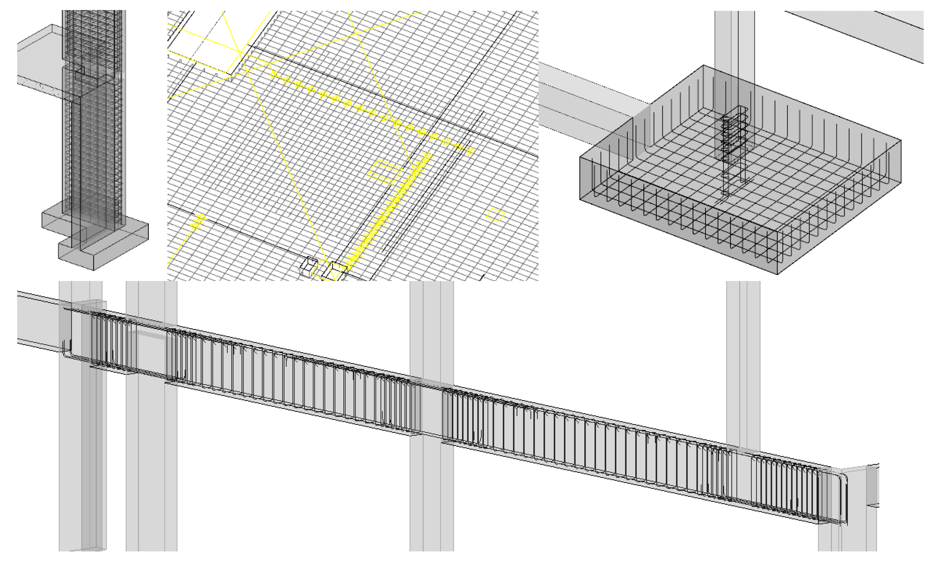
One of the aspects of the BIM methodology is the ability to extract different types of information from the model. After the structure model, with all the reinforcements inserted on it, is exported from the structure system to the modelling tool, it is then possible to obtain maps of quantities, budgeting, and sheets of drawings organized with plants, cross-sections, and diverse type of tables (Figure 16).
In addition, different types of tables referring to quantities of material, concrete and steel, listed by elements, floors, volumes or diameters of rods, and formwork areas are obtained. Quantity slot tables can be used to support project budgeting and wire maps at construction site or prefabrication. To define tables of quantities take-off (QTO), the user selects as filters the required structure components and materials and a list of elements is presented with the weight of concrete or the extension of bars (Table 1). These values can be obtain from each model, after being completed with all the required reinforcements. Revit and other modelling BIM software incorporate the ability of automatically quantifying any type of materials (steel and concrete) or construction components (slabs, columns or walls) by type of elements (C20x20 or C20x30), parts of the building (blocks or humid zones), levels (underground or roof), or physical and mechanical proprieties (characteristics associated to the parametric objects used on the generation of the model). For that, the type of data required should be considered as a filter on the generation of specific tables. The unit prices for each material can be also associated to the parametric objects used on the modelling process, supporting the budgeting task. Then the tables can be exported to Excel and a detailed project budget can be performed.
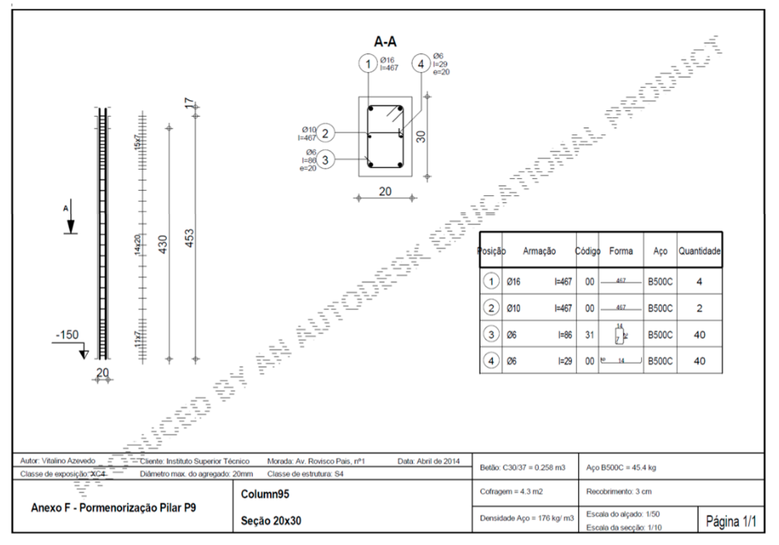
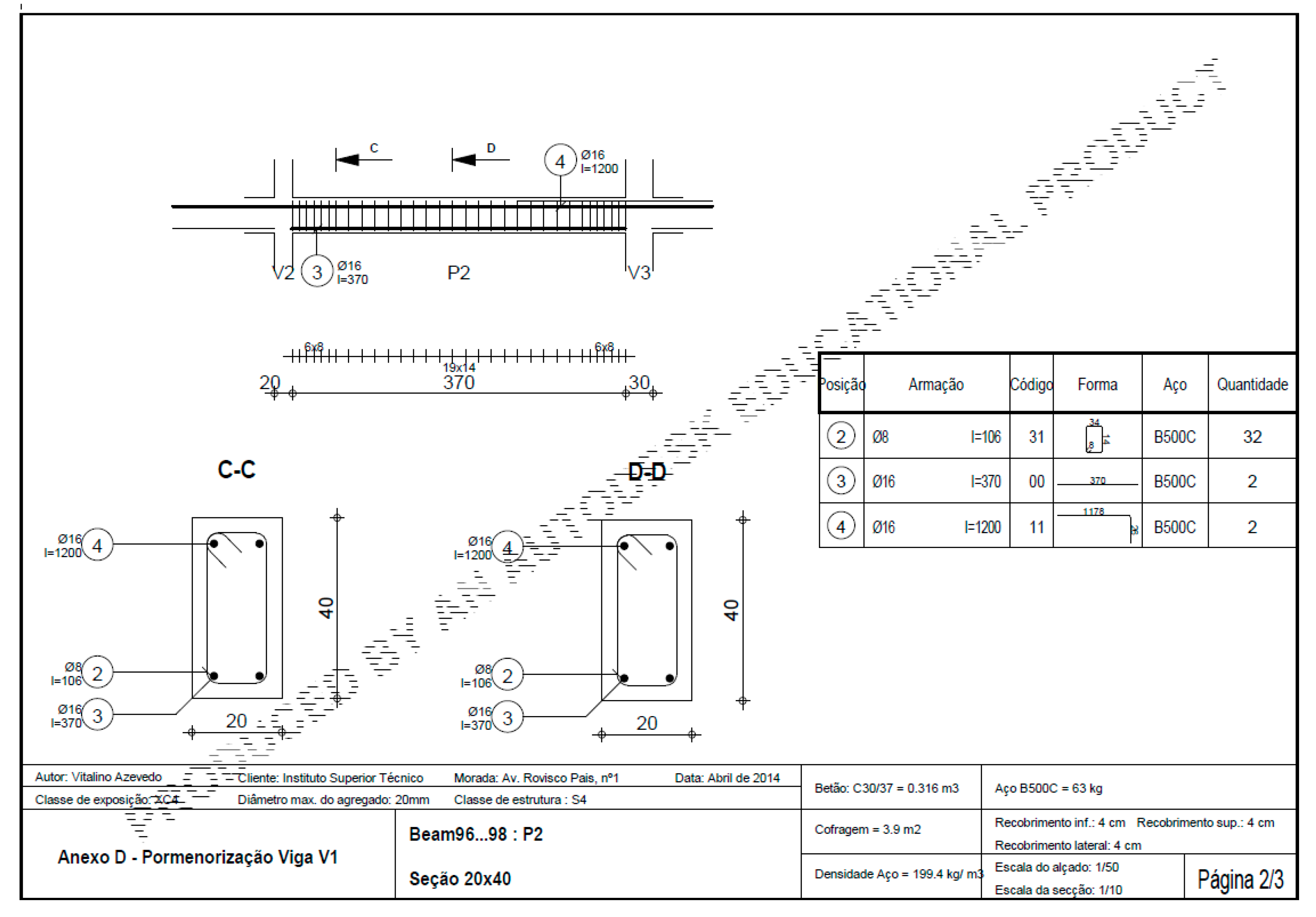
Using the modelling systems capacity, the design sheets are obtained, organized according to the usual form of presentation of the graphical documentation of the project (Figure 17).
4. Results and Discussion
This section summarizes the relation between the software used and the related problems found. This paper is an important contribution to the better knowledge for structural engineers when choosing BIM tools to support their work. Normally the users of a specific software, belonging to Autodesk, Bentley, or Graphisoft, first explore the BIM tools most advanced of the same house, but this research revels what are the BIM tools, among those studied, that currently present a better performance. However, the technological investigation associated with BIM is growing each day in order to achieve improved results, where the interoperability aspect is currently the main topic of research. In the present study, several tools were used and two ways data flow were analyzed:
- Structural model generation: For the development of the BIM model of the structural solution establish for each building case of distinct size and complexity, all software used are adequate, as they present the ability of defining and applying parametric objects, realistic in configuration and in mechanical proprieties. The software used were Revit (Autodesk), AECOsim (Bentley), and ArchiCAD (Graphisoft);
- Checking geometric consistency: All modelling systems allow the visualization of the correspondent analytical model and over it the user can correct any verified inconsistency;
- Transfer of models: The performance of the combination of tools modeling/structure is distinct depending of the software used:
- -
- Revit/Robot presents the most efficient transfer process requiring only a few adjustments, as the stairs and foundations elements were missing;
- -
- In Revit/SAP exchange the main structure elements were identified except the stairs and foundations components, and the axis of linear finite elements and the rigid links were not well recognized;
- -
- The export ArchiCAD/ETABS procedure brings a great number of nodes disconnected between adjacent elements, needing a relevant complementary work before analyses;
- -
- Concerning AECOsim/SAP transfer the process is associated with the lack on the identification of foundations, stairs, and border conditions, however SAP presents the ability to join automatically the nodes that are distant between the axis ends.
- Loads application and reinforcement detailing: Each structural system can easily perform the loads and the mandatory loads combination. Also all structural tools present advanced functionalities allowing the complete definition of the reinforcements in the structural elements.
- Transfer of reinforcements: The exchange data process required after the structural analyses, in order to centralize all the produced information, is the most inefficient task in all the structural BIM design procedure:
- -
- When exporting Robot/Revit reinforcements the accuracy of data is verified. Concerning slabs, beams, columns, and foundations, Revit revels inefficiency as the reinforcements included in those elements were transferred with several inaccuracies. Namely, the bars of multi-span beams exceed their limits, the stirrups of the beams presents duplication, and the reinforcements of slabs and foundations are not recognized. An important additional work is then required;
- -
- The SAP/Revit transfer does not recognize any bar associated to each structural element and the necessary reinforcement detailing must be elaborated in the modelling tool;
- -
- The reinforcements export in ETABS/ArchiCAD transfer was first made using IFC format, but the results were deficient. As so, the detailing work was then totally performed in ArchiCAD, supported on the analyses result.
- -
- The SAP/AECOsim transfer process is effectuated in an automatic mode but the walls elements, the loads, and the border conditions were not recognized.
Based on the analyses of the results, some benefits and limitations were carried out. There are advantages in the use of integrated Revit/Robot platforms, based on the use of native format of data. But when using IFC format to execute the necessary models transfer between systems a relevant level of inefficacy, is verified. It was found that data flow toward modeling/calculation could be done with great confidence, while the data flow in the reverse way is still limited. While the reinforcement definition made on beams and columns, in Robot, was satisfactorily transferred to Revit, the bars inserted in slabs and foundations were not correctly recognized, requiring additional work of detailing.
5. Conclusions
The study allows to evaluated the current degree of interoperability verified between the BIM-based modeling and the structure analyses systems, most often used, when applied in the structure design context. The findings of this investigation were focused mainly on the analyses of the interoperability limitations associated to the transfer process of models between software. But the modelling process in each case and using distinct BIM-modelling tools was found easy to perform, as it is based on the use of adequate parametric objects. For Autodesk users (AutoCAD and Revit) this benefit is more evident as the interfaces are basically similar. The detailed analyses worked out over the performances of each transfer processes bring additional knowledge to experimented structural engineers that normally develop their project based on the traditional modes. Although BIM tools support the work of carrying out the design of structures with many benefits, the study presents, however, a considerable amount of complementary work that is necessary to perform, especially regarding the reinforcement detailing.
The advantages are essentially related to the easy initial modeling task, some degree of interoperability verified in the process of transfer structural models between the modelling and calculation systems, the facility of defining the detailing reinforcement in all elements, using the functionalities available in the modeling tool and also the BIM tools capacity to obtain technical drawings and tables of material quantities. Finally it is noted that the biggest drawback of BIM implementation in the project office is the learning time that is required to start the BIM concept approach in particular when oriented to the structural sector.
Author Contributions
Conceptualization, methodology and investigation, A.Z.S.; Validation and formal analysis, A.M.G. All authors have read and agreed to the published version of the manuscript.
Funding
This research received no external funding.
Institutional Review Board Statement
Not applicable.
Informed Consent Statement
Informed consent was obtained from all subjects involved in the study.
Data Availability Statement
Not applicable.
Conflicts of Interest
The authors declare no conflict of interest.
References
- Mehran, D. Exploring the Adoption of BIM in the UE Construction Industry for AEC Firms. Procedia Eng. 2016, 145, 1110–1118. [Google Scholar] [CrossRef] [Green Version]
- Gao, X.; Bozorgi, P.P. BIM-enabled facilities operation and maintenance: A review. Adv. Eng. Inform. 2019, 39, 227–247. [Google Scholar] [CrossRef]
- Sacks, R.; Eastman, C.M.; Teicholz, P.; Lee, G. BIM Handbook: A Guide to Building Information Modeling for Owners, Designers, Engineers, Contractors, and Facility Managers, 3rd ed.; John Wiley & Sons, Inc.: Hoboken, NJ, USA, 2018; p. 688. ISBN 978-1-119-28755. [Google Scholar]
- Bozorgia, P.P.; Gao, X.; Eastman, C.; Alonzo, P.S. Planning and developing facility management-enabled building information model (FM-enabled BIM). Autom. Constr. 2018, 87, 22–38. [Google Scholar] [CrossRef]
- Migilinskas, D.; Popov, V.; Juocevicius, V.; Ustinovichius, L. The Benefits, Obstacles and Problems of Practical Bim Implementation. Procedia Eng. 2013, 57, 767–774. [Google Scholar] [CrossRef] [Green Version]
- NIBS News & Press. BIM Educational Strategy the Focus of National Institute of Building Sciences Conference. Building Innovation. 2013. Available online: http://www.nibs.org/news/113631/ (accessed on 8 February 2021).
- Mohamed, A.G.; Abdallah, M.R.; Mohamed, M. BIM and semantic web-based maintenance information for existing buildings. Autom. Constr. 2020, 116, 103209. [Google Scholar] [CrossRef]
- Sampaio, A.Z. BIM as a Computer-Aided Design methodology in Civil Engineering. Int. J. Softw. Eng. Appl. 2017, 10, 194–210. [Google Scholar] [CrossRef] [Green Version]
- BuildingSMART, Industry Foundation Classes (IFC)-buildingSMART Technical. 2019. Available online: https://technical.buildingsmart.org/standards/ifc/ (accessed on 8 February 2021).
- Ilter, D.; Ergen, E. BIM for building refurbishment and maintenance: Current status and research directions. Struct. Surv. 2015, 33. [Google Scholar] [CrossRef]
- Vilutiene, T.; Kalibatiene, D.; Hosseini, M.R.; Pellicer, E.; Zavadskas, E.K. Building Information Modelling (BIM) for Structural Engineering: A Bibliometric Analysis of the Literature, Hindawi. Adv. Civ. Eng. 2019, 19. [Google Scholar] [CrossRef]
- Shin, T.S. Building information modeling (BIM) collaboration from the structural engineering perspective. Int. J. Steel Struct. 2017, 17, 205–214. [Google Scholar] [CrossRef]
- Subramani, T.; Ammai, A. Maturing construction management up the BIM model and scheduling using primavera. Int. J. Eng. Technol. 2018, 7. [Google Scholar] [CrossRef] [Green Version]
- Musella, C.; Serra, M.; Salzano, A.; Menna, C.; Asprone, D. Open BIM standards: A review of the processes for managing existing structures in the pre- and post-earthquake phases. Civ. Eng. 2020, 1, 291–309. [Google Scholar] [CrossRef]
- Araszkiewicz, K. Digital technologies in facility management—The state of practice and research challenges. Procedia Eng. 2017, 196, 1034–1042. [Google Scholar] [CrossRef]
- Sampaio, A.Z.; Novais, J.N.; Diniz, J.P. Analysis of BIM implementation in structural projects. In Proceedings of the Congress of Numerical Methods in Engineering; Lourenço, P.B., Flores, P., Clain, S., Eds.; University of Minho: Guimaraes, Portugal, 2019. [Google Scholar]
- Azevedo, V.S. Analysis of the BIM Model from a Design Perspective. Master’s Thesis, Civil Engineering, University of Lisbon, Lisbon, Portugal, 2015. [Google Scholar]
- Farinha, T.S. Analysis of the Transfer Process of Information between Structure Models in a BIM Environment. Master’s Thesis, Civil Engineering, University of Lisbon, Lisbon, Portugal, 2018. [Google Scholar]
- Serra, P.M. Analysis of the Implementation of BIM Processes Applied in Structure Design. Master’s Thesis, Civil Engineering, University of Lisbon, Lisbon, Portugal, 2015. [Google Scholar]
Figure 1.
Initial modeling statements (alignments), parametric objects (columns, beams, and foundations), and mechanical properties of materials (cement).
Figure 1.
Initial modeling statements (alignments), parametric objects (columns, beams, and foundations), and mechanical properties of materials (cement).

Figure 2.
Structure model of a tall building created in Revit.

Figure 3.
The architectural and structural models of a ground floor house were created using Revit.

Figure 4.
Models of architecture and structures (physical and analytical) created using Revit.

Figure 5.
Models of architecture and structures of a hotel building created using ArchiCAD.

Figure 6.
Models of a technical building of a dam created in AECOsim.

Figure 7.
Structural models transferred from Revit to Robot.

Figure 8.
Structure model transferred from Revit to SAP.

Figure 9.
Structure model transferred from ArchiCAD to ETABS.

Figure 10.
Export of the structure component from AECOsim to SAP.

Figure 11.
Rebar detailing in structure elements (Robot).

Figure 12.
Diagram of moments in a beam and reinforcements detailing drawing (SAP).

Figure 13.
Diagrams of moments and deformations in a slab and the reinforcement details (ETABS).

Figure 14.
Transfer of structure models with reinforcements from Revit to Robot.

Figure 15.
Reinforcement functionalities of Revit.

Figure 16.
Segments of the structure models with reinforcements and maps of quantities of bars.

Figure 17.
Sheets of drawings with reinforcement details and tables of quantities.


Table 1.
Maps of quantity take-off of concrete and steel of walls and columns.
| Walls | ||||
|---|---|---|---|---|
| Type | Volume of Concrete (m3) | Volume of Bars (cm3) | Weight of Steel (kg) | Area (m2) |
| W0_0.20 | 34.48 | 391,841.14 | 3075.95 | 172 |
| W1_0.20 | 8.23 | 167,146.46 | 1312.10 | 41 |
| Total | 42.72 | 558,987.60 | 4388.05 | 214 |
| Columns | ||||
| Type | Volume of Concrete (m3) | Volume of Bars (cm3) | Weight of Steel (kg) | Extension (m) |
| C20x20 | 0.81 | 11,171.50 | 87.70 | 21 |
| C20x40 | 2.09 | 21,969.15 | 172.46 | 27 |
| C20x60 | 2.44 | 23,238.37 | 182.42 | 21 |
| C30x35 | 0.30 | 2909.11 | 22.84 | 3 |
| C35x40 | 0.80 | 5695.71 | 44.71 | 6 |
| Total | 6.43 | 64,983.84 | 510.12 | 78 |
Publisher’s Note: MDPI stays neutral with regard to jurisdictional claims in published maps and institutional affiliations. |
© 2021 by the authors. Licensee MDPI, Basel, Switzerland. This article is an open access article distributed under the terms and conditions of the Creative Commons Attribution (CC BY) license (http://creativecommons.org/licenses/by/4.0/).
Share and Cite
MDPI and ACS Style
Sampaio, A.Z.; Gomes, A.M. BIM Interoperability Analyses in Structure Design. CivilEng 2021, 2, 174-192. https://0-doi-org.brum.beds.ac.uk/10.3390/civileng2010010
AMA Style
Sampaio AZ, Gomes AM. BIM Interoperability Analyses in Structure Design. CivilEng. 2021; 2(1):174-192. https://0-doi-org.brum.beds.ac.uk/10.3390/civileng2010010
Chicago/Turabian StyleSampaio, Alcinia Zita, and Augusto Martins Gomes. 2021. "BIM Interoperability Analyses in Structure Design" CivilEng 2, no. 1: 174-192. https://0-doi-org.brum.beds.ac.uk/10.3390/civileng2010010