
Bidirectional Loading History for Seismic Testing of 3D Frame Joints


Institute of Construction Materials, University of Stuttgart, Pfaffenwaldring 4, 70569 Stuttgart, Germany
*
Author to whom correspondence should be addressed.
CivilEng 2021, 2(2), 349-369; https://0-doi-org.brum.beds.ac.uk/10.3390/civileng2020019
Submission received: 26 February 2021
/
Revised: 15 April 2021
/
Accepted: 30 April 2021
/
Published: 3 May 2021
(This article belongs to the Special Issue Connections in Concrete)
Abstract
:Beam-column-joints (BCJ) in reinforced concrete (RC) frames are known to be critical against seismic actions. Hence, several researchers have conducted related investigations. The loading history used in the experimental investigations must be a sufficiently accurate and conservative representation of seismic loading on the structure and should trigger all possible critical failure mechanisms in the subassembly. Presently, there is significant diversity in the loading histories used for seismic investigation of structural subassemblies. This paper intends to propose an optimum loading history for considering bidirectional (horizontal) seismic action on 3D-RC BCJ subassemblies. To this end, the available loading histories (unidirectional and bidirectional) for simulation of seismic loads on RC joint subassemblies are reviewed in the context of the demands they impose on the joints. Finite element modeling and analyses are used as a tool for investigating the response of 3D-BCJ subassembly under different bidirectional loading states.
1. Introduction
Reliable assessment of the capacity of a structural system is crucial for its performance evaluation and design. The definition of the structural capacity of a given system has two characteristic components (i) material properties and the mechanical interaction that governs the strength and deformations and (ii) mode of load transfer for which the capacity is being evaluated. The mode of load transfer depends on how external actions act on the structural system. For example, the capacity of a column is verified against axial loads, shear loads, flexural loads and combined axial and flexural loads. While material properties and mechanical interaction govern the magnitude of this capacity, each individual capacity is also characterized by how external forces act. The magnitude of these external forces falls in the domain of the demand on the structural system. The mode and mechanics of load transfer constitute the background in which a comparison of demand and capacity is done for the purpose of evaluation and design. The manner in which the load is applied is popularly referred to as loading history or protocol. The loading protocol is defined as how external actions (loads or displacements) are incrementally applied to a structural system to evaluate its behavior and capacity under the given load transfer mechanism. Early studies [1,2] showed that capacity evaluation of structural subassemblies was a function of the employed loading protocol.
The present work focuses on loading protocols simulating seismic action through bidirectional (horizontal) loading of 3D beam–column joint (BCJ) sub-assembly. The primary objective of such loading protocols is to evaluate the seismic performance of BCJs so that one could decide whether the desired performance objectives are satisfied. Seismic performance is characterized by specifying the load capacity, its degradation at high drift levels (expressed as ductility) and hysteretic energy dissipation under cyclic action. For capacity evaluation, the cyclic load is applied in a pseudo-static manner with specific increments in the drift levels, as dictated by the loading protocol. The resulting cyclic load–displacement characteristics are analyzed for the stiffness and damping at the subassembly level as a function of drift. When expressed at the structural level, the stiffness and damping of individual sub-assemblies provide the structural stiffness and damping. The seismic demand on the structure is a function of the evaluated structural stiffness and damping. In this context of seismic considerations, it can be emphasized that the definition of loading protocol is crucial for effective communication between the loaders [3] (those involved with defining the point loads at structural frame level) and jointers [3] (those who evaluate sub-assembly characteristics particularly at frame joints). The loading protocol for a bidirectionally loaded BCJ is required to translate the bidirectional seismic action at the structural-frame level onto the sub-assembly level so that the evaluated structural characteristics at the subassembly levels correspond to the actions being considered at the structural level. Furthermore, it is essential to define performance assessment criteria at the subassembly level, which ensures that the subassembly behavior is coherent with the assumption of stiffness and damping, which govern the seismic demand.
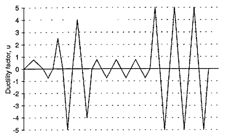
Several organizations from the world over have contributed to the vast experimental, numerical and analytical database related to the behavior of RC BCJs over the last decades. While most of these studies were focused on unidirectional load application, some studies are also available with bidirectional load application. One of the earliest records of cyclic testing of BCJ subassembly by Hanson and Connor [4] used a unidirectional cyclic loading protocol with displacement levels expressed in terms of the ductility factor (ratio of displacement level of cycling to the calculated yield displacement of the subassembly), as shown in Figure 1. The peak displacement of the first cycle (elastic) corresponded to 75% of the yield load. The following two inelastic cycles (no. 2 and 3) represented a major earthquake. The inelastic cycles representing the first major earthquake were followed by three elastic cycles (no. 4 to 6) to assess the behavior after the major earthquake. The three final inelastic cycles (no. 7 to 9) represented the second major earthquake. Higashi et al. [1] studied the influence of different unidirectional cyclic loading histories on companion specimens, with either 3 or 10 cycles at each level of displacement. The results indicated that the number of cycles between 3 and 10 did not alter the response significantly. Jirsa [2] compared the different loading protocols in use up to 1977. The work discussed the influence of loading history on the evaluated experiment data and highlighted the need for a more thoughtful comparison of the test results in the context of the loading protocols. Studies on BCJ subassemblies under unidirectional excitation in the last quarter of the 20th century and the 1st quarter of the 21st century again show a diversity in the loading protocols used. Some studies [4,5,6,7] have reported using loading history with one cycle at each displacement level, while others [8,9,10,11] have reported using three cycles for each level of inelastic displacement. Most studies reported during the US–NZ–Japan (and later China) joint conferences [3,12,13,14,15,16,17,18,19,20] on BCJ behavior (1984 to 1989) used a loading history with two cycles at each displacement level. More recent studies [10,21,22,23,24,25,26] under unidirectional loading with two cycles at each inelastic displacement level have also been reported.
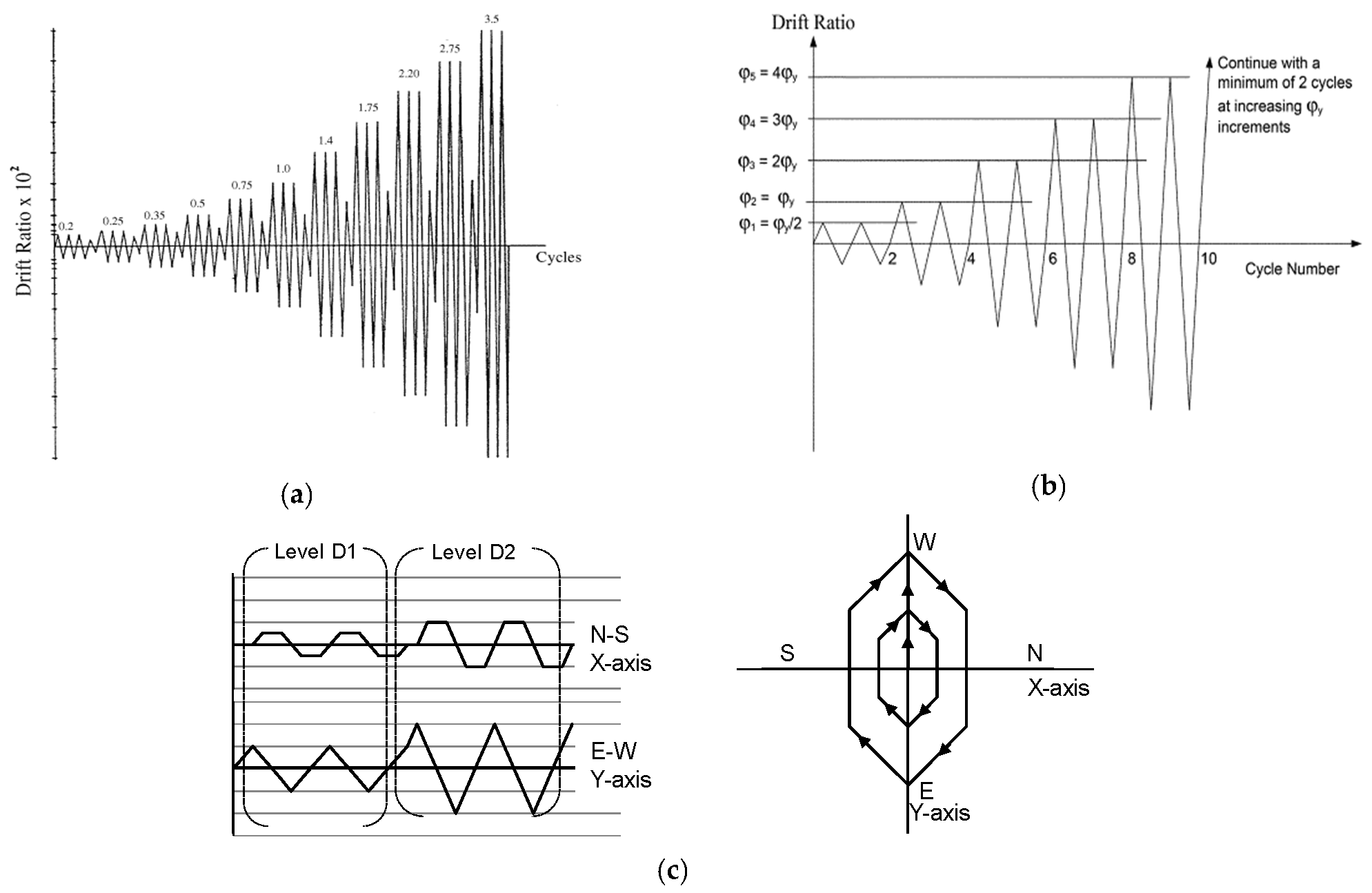
In the course of development, it was natural to define and standardize the loading protocol and assessment criteria for subassembly configurations. ACI-374.1-05 [27], published in 2005, provides a loading protocol expressed in terms of drift levels, with three cycles at each level (see Figure 2a). The evaluation procedure and assessment criteria based on the test results are also provided. ACI-318-19 [28] refers to ACI-374.1-05 [27] for loading protocols to establish design procedures based on laboratory tests and validated analyses. The ACI committee 374 published a guideline document for testing RC elements under seismic loads applied in a pseudo-static cyclic manner (ACI-374.2-R13 [29]) in 2013. The guide recommends a cyclic loading protocol specified in terms of ductility ratios with a minimum of two cycles at each displacement level (see Figure 2b). The guideline acknowledges the common use of three cycles at each displacement and states that a minimum of two cycles is sufficient to incur damage associated with the number of cycles at a given drift level. However, the decision of the number of cycles required at each displacement level is left to the researcher since; it may be specific to the characteristics of the system being tested. It is noted here that, while the loading protocol in Figure 2a is expressed in terms of specific drift levels, the one in Figure 2b is expressed in terms of ductility levels. By specifying levels of cycling in terms of the ductility ratio, the researcher can ensure that the first level of cycling is always in the elastic range.
For unidirectional seismic loading, it can be summarized that the pseudo-static cyclic loading protocols in research, as well as guidelines, consist of cycles with increasing magnitudes of displacements, starting at the elastic level. However, both in research and the guidelines, there exist nonuniformity in the number of cycles required or used at any displacement level. Some research studies use two cycles at each level of displacement, while many others use three cycles at each level of displacement as is recommended in ACI-374.1-05 [27]. A few studies with one cycle at each displacement level are also available.
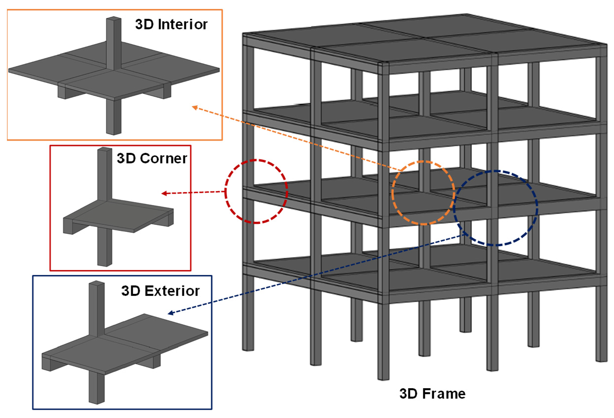
Although ACI-374.1-05 [27] recommends cyclic testing of 3D BCJ sub-assemblies (different possible configurations shown in Figure 3) when required by the designers, it remains silent about the relative magnitude of displacements required to be applied in the two framings (horizontal) directions. ACI-374.2-R13 [29] specifies a procedure for bidirectional loading based on the provisions of FEMA-461 [30], as seen in Figure 2c. As per this bidirectional loading protocol, the E–W (y-axis) is the primary loading direction. When the displacement in this primary direction is at the peak, the displacement in the transverse direction (N–S or x-axis) is zero. The application of the displacement in the lateral direction as a function of displacement in the primary direction is represented in Figure 2c. The maximum simultaneous displacement in both the loading direction is equal to half the peak displacement in the given cycle.
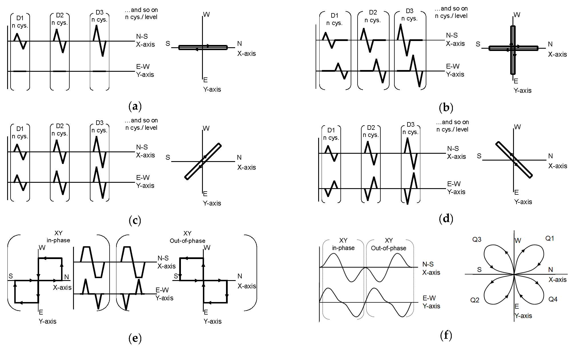
Research studies using bidirectional loading are also available; however, there is again a diversity in the loading protocols adopted by different research groups. The need for extensive research to evaluate the influence of bidirectional loading was reported [2] back in 1977. There are different possible bidirectional loading protocols for 3D BCJ sub-assemblies, as schematically represented in Figure 4. Comparative studies of unidirectional loading and different cases of bidirectional loading on 3D internal BCJ (Figure 3) were reported [31,32,33,34] in the last quarter of the 20th century. These studies investigated 3D interior BCJs (Figure 3) with and without slabs under the influence of different loading protocols. Unidirectional protocol (Figure 4a), bidirectional alternating protocols (Figure 4b) and bidirectional simultaneous protocols (Figure 4c,d) were used in these studies with 3 cycles at each displacement level. It is noted here that for 3D interior joints with symmetric configuration in the plan, the in-phase (Figure 4c) and out-of-phase (Figure 4d) bidirectional simultaneous loading histories tend to be equivalent. However, this may not be the case for 3D exterior or 3D corner BCJs (Figure 3). The loading history used for testing of 3D BCJ subassemblies in the research published during the US–NZ–Japan (and later China) [16,17,18,20] joint conferences was a combination of unidirectional (Figure 4a), bidirectional alternating (Figure 4b) and shape-of-8 (in-phase as well as out-of-phase in Figure 4e). The loading sequence can be described in five phases—(i) 2 cycles of unidirectional loading at elastic displacement level (DF < 1), (ii) one set of bidirectional alternating cycles at DF = 1, (iii) two unidirectional cycles followed by two sets of in-phase shape-of-8 cycles at DF = 2, (iv) two unidirectional cycles followed by two sets of out-of-phase shape-of-8 cycles at DF = 4 and (v) two sets each of out-of-phase shape-of-8 cycles for DF = 6 and DF = 8. The majority of these studies focused on 3D interior BCJs; however, some studies on the 3D exterior and 3D corner BCJ were also reported. It is noted here that the bidirectional loading used in these studies corresponds to effectively two cycles at each displacement level. In the 1st quarter of the 21st century, a cloverleaf-shaped loading protocol schematically represented in Figure 4f was proposed [35,36]. One set of this loading protocol at a given displacement level constitutes in-phase (Q1–Q2) and out-of-phase (Q3–Q4) simultaneous loading. The loading protocol was used for the study of the 3D corner joint. Recently, reported experimental studies on 3D corner BCJs [37,38] employed the bidirectional alternating protocol with two cycles at each displacement level.
It is noted here that, while most of the above studies have focused on seismically detailed beam–column connections (2D and 3D), relatively fewer studies are available with non-seismically detailed 2D beam–column joints. Only limited data are available for non-seismically detailed 3D BCJ. It is also noted here that non-seismically detailed BCJ (typical for several existing structures) are more vulnerable to seismic actions.
2. Motivation and Objective
This paper presents a thoughtful comparison of the different bidirectional loading protocols that have been reported for seismic evaluation of 3D-RC BCJ. The discussion is presented in a way that appeals to both loaders [3] (who define point loads in structure) and jointers [3] (who evaluate joint characteristics). The focus of comparison is on the interpretation of evaluated response parameters that are communicated between the loaders and the jointers. A validated FE modeling approach is used as a tool to generate additional analytical data for the intended discussions. A rationalized proposal for bidirectional loading protocol for a 3D BCJ is presented.
3. Comparing the Different Bidirectional Protocols
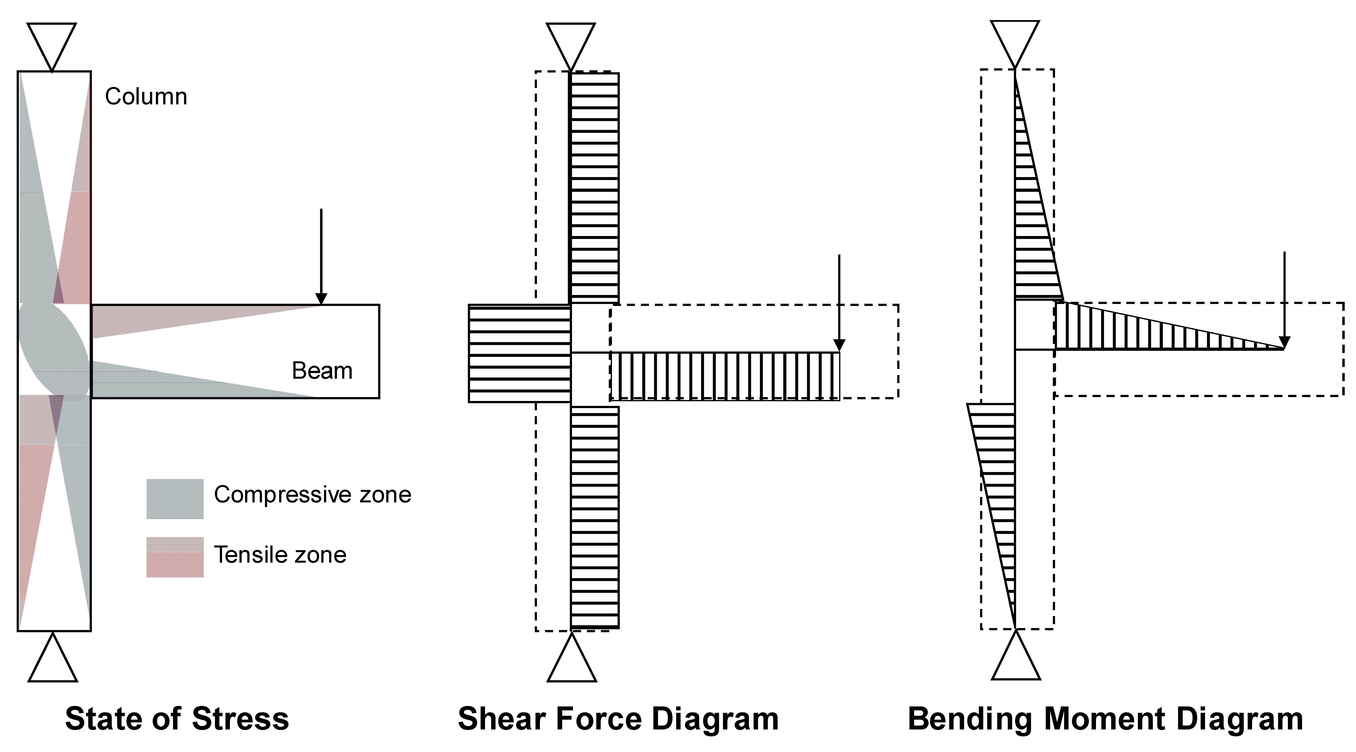
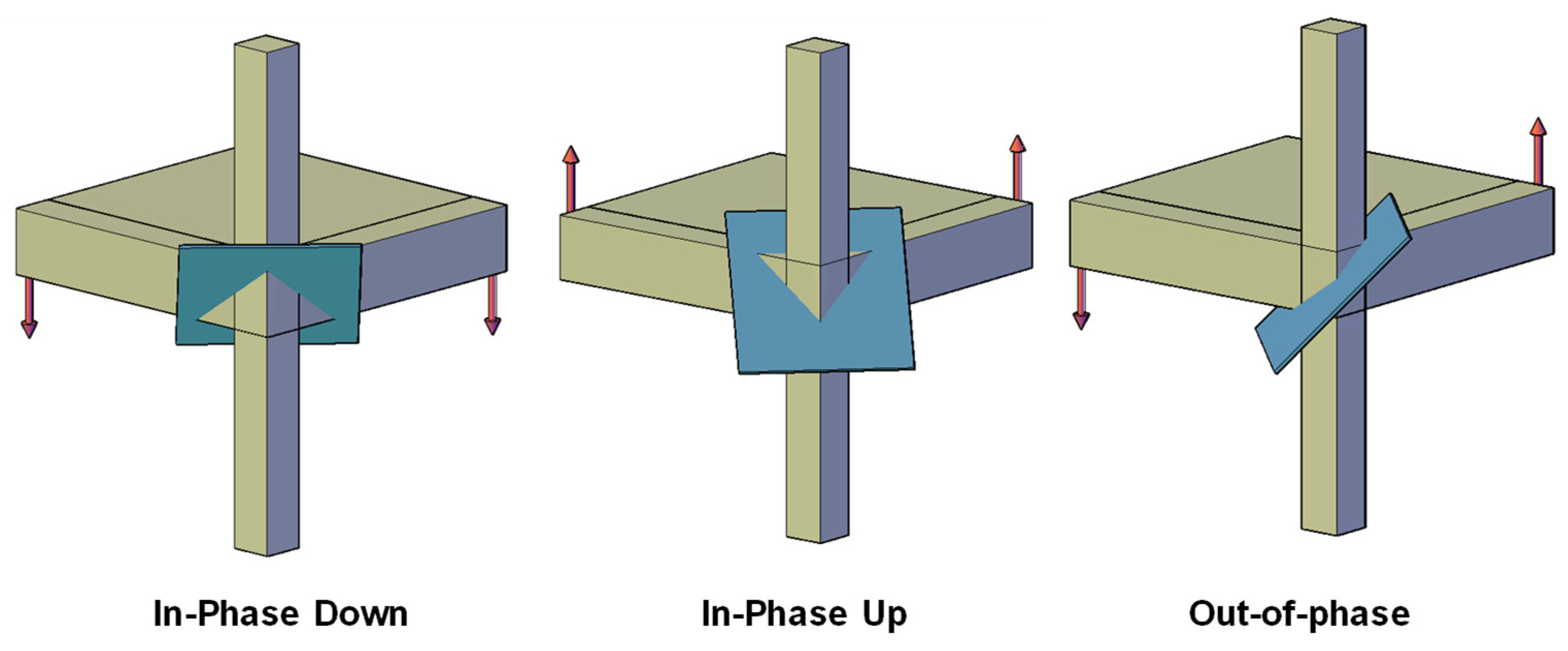
The 3D corner BCJ (Figure 3) is selected for study and discussions in this paper. The reason for this selection is that the configuration offers the maximum bidirectional asymmetry, and the response to in-phase and out-of-phase bidirectional loading is distinctly different. For each of the two horizontal directions, the lateral force (story shear) leads to a bending moment profile along the column axis, in which a change from maximum positive to maximum negative moment occurs over the relatively small length corresponding to the beam depth (See Figure 5). This introduces high magnitudes of joint shear stresses in both directions. Joint shear failure in BCJs is a critical failure mode that should never dominate and govern the joint subassembly [39]. Under the action of the forces resulting in the BCJ subassembly, a compression strut is formed in the joint region along the diagonal plane, as shown in Figure 5. This plane is also the one in which the main diagonal crack because of joint shear is generated. In the case of bidirectional loading, the orientation of this critical plane in which the joint strut is formed is a function of the relative magnitudes of the loading actions in the two directions. Figure 6 shows the orientation of this critical plane for different bidirectional loading cases. The beams and slab connected to the joint core provide confinement to possible strut formation and influence the capacity. In a 3D interior joint, since beam and slab are present at all sides of the joint core, each of the inclined critical planes under bidirectional loading is identical w.r.t the confinement offered by the beam and slab boundary. On the other hand, for the 3D corner joint, as shown in Figure 6, each case is distinctly different. Thus, it can be concluded here that the performance of a 3D corner BCJ is a function of the protocol of bidirectional loading.
Studies on BCJ subassemblies intend to express their performance in terms of loads, ductility, energy dissipation and damping, which can be compared with the established assessment criteria [27] for approval and, if required, translated on to a structural frame level for further evaluation and processing [40]. The performance or response of 3D corner BCJ is a function of the relative magnitudes of the loads acting in the two framing directions. Hence, it becomes essential to study the response of 3D corner BCJ under different loading protocols. The same is addressed in this paper by using validated FE modeling and analysis procedure as a tool. However, before proceeding any further, it is essential to first perceive the different available bidirectional loading protocols (Figure 3c and Figure 4) in terms of the demands they impose on the BCJ subassembly. The demand can be expressed in terms of relative loading (in the form of applied displacement) in each framing direction and in terms of cumulative ductility imposition [12] for a given set of cycles.
Consider one set of cycles, as shown in Figure 3c and Figure 4, for an inelastic displacement level equal to where is the nominal displacement of the BCJ subassembly corresponding to elastic limit and is the ductility corresponding to the imposed displacement level. In the unidirectional protocol (Figure 4a), the horizontal cycling load is applied in one of the framing directions (N–S axis) only. The displacement in the other framing direction is always zero. Thus, one set of cycles consists of two peaks (1 positive and one negative) at the inelastic displacement level. ACI-374.2-R13 [29] recommends a minimum of two such sets of cycles for capturing cycling damage at a given displacement level in a sufficient manner. However, as discussed earlier, the available research studies have used one, two or three sets of cycles in their experiments. The cumulative ductility imposed in one complete unidirectional cycle . In Table 1, the imposed displacement and cumulative ductility corresponding to one set of the cycle for different loading histories in Figure 3c and Figure 4 are summarized. The presented values correspond to one set of cycles at a given inelastic displacement level equal to . The maximum displacement imposed along the N–S and the E–W axes are provided in columns 2 and 3, respectively. When the imposed displacement is maximum along one of the axes, the relative magnitude of displacement in the other direction is shown in column 4 as the ratio of displacement N–S:E–W. The absolute magnitude of the maximum displacement applied simultaneously in both the direction expressed relative to the displacement level of cycling is provided in column 5. The cumulative ductility imposed on the subassembly in one set of the cycle is provided in column 6.
One set of bidirectional loading cycles typically consists of unidirectional cycles acting in both the horizontal framing direction. Depending on the relative magnitude and direction of the applied displacement in each of the two directions at any point of the loading history, different types of protocols, as shown in Figure 3c and Figure 4, are possible. Bidirectional loading of type (i) alternating, (ii) simultaneous and (iii) shape-of-8 have the identical maximum level of imposed displacement in each framing direction. The loading histories are, however, different. In the bidirectional alternating protocol [37,38] (Figure 4b), a cycle of loading in one framing direction is followed by a loading cycle in the other framing direction. Thus, in alternating bidirectional loading, one complete bidirectional loading cycle consists of four peaks at a given displacement level and corresponds to a cumulative ductility . That at any given time, the loading acts only in one framing direction is a characteristic feature of alternating bidirectional loading. In other words, there is no simultaneous imposition of the x and y horizontal displacements, as is seen in Figure 4b.
In case of simultaneous bidirectional loading Figure 4c,d, both the horizontal directions are loaded simultaneously, equal in magnitude, within the resultant displacement vector at 45° to the framing direction. In in-phase simultaneous loading, the positive peak in one direction occurs simultaneously with a positive peak in the other direction, whereas in out-of-phase simultaneous loading, the positive peak in one direction of loading occurs along with the negative peak in the other direction. In this loading type, one complete bidirectional cycle consists of four peaks at a given displacement level and correspond to a cumulative ductility . For an interior 3D BCJ with bidirectional symmetry, the in-phase and out-of-phase simultaneous loading are equivalent. However, for the 3D exterior or corner joint, the response of the joint for the two cases of simultaneous loading is expected to be different.
The shape-of-8 bidirectional protocol (Figure 4e) was used as a part of loading history for investigations on BCJs, performed during the US–NZ–Japan–China conferences and workshops [16,17,18,20]. One bidirectional cycle was either in-phase or out-of-phase, as shown in Figure 4c. One shape-of-8 bidirectional cycle (in-phase or out-of-phase) consists of four peaks at the displacement level and correspond to a cumulative ductility . Two such bidirectional cycles were applied at a given displacement level. The difference between the shape-of-8 and the simultaneous protocols is the angle of the resultant displacement at any given time of the loading history. While for simultaneous loading, the resultant displacement vector is always at 45° to the horizontal framing direction, this angle varies between 0° and 90° for shape-of-8 type loading. Thus, in the case of shape-of-8 bidirectional protocol, the peak displacement in one framing direction occurs simultaneously with the varying magnitudes of displacement between zero and peak in the other direction.
The cloverleaf-shaped loading history [35,36] (shown in Figure 4f) is essentially a combination of in-phase and out-of-phase shape-of-8 loading history expressed in the form of a continuous sinusoidal function. One set of the cloverleaf-shaped loading history is equivalent to two sets or cycles of other bidirectional histories discussed so far. This is reflected by the cumulative ductility of which results in this case. At the point of loading history, when the displacement in one of the framing directions is at maximum, the displacement in the other framing direction is 0.54 times the maximum value. Furthermore, the maximum simultaneous displacement applied (resultant displacement vector at 45°) corresponds to 94% of the maximum displacement level in each individual direction.
The bidirectional loading history proposed in ACI-374.2-R13 [29] is distinctly different from the other histories considered above. In this protocol, the E–W axis acts as a primary loading direction along which the maximum displacement imposed corresponds to the displacement level . The N–S axis acts as a secondary loading direction, and the maximum displacement imposed in this direction corresponds to half the cycling displacement level. The protocol is such that when the displacement in the primary direction is at its maximum, the displacement in the orthogonal direction is zero. The post-peak transition along the primary direction from the peak displacement to half of the peak displacement is accompanied by an increase of displacement up to 50% of the peak displacement in the lateral direction. Hence, the maximum displacement applied simultaneously in both the framing directions corresponds to half of the level of cycling displacement. The cumulative ductility imposed in one set of cycles is equal to . ACI-374.2-R13 [29] recommends applying two sets of loading cycles for each displacement level.
The available bidirectional loading protocols in the literature have been discussed w.r.t. the displacement and cumulative ductility that they impose. The next obvious step would be to decide which loading protocol is more appropriate or suitable to simulate the effects of seismic loading on joint behavior. A suitable or appropriate loading protocol should fulfill two essential requirements: (i) It should be representative of the seismic loading (ii) It should trigger all possible loading mechanisms in a way to arrive at possibly the lowest bound of the capacity. With the comparison of different loading protocols w.r.t. the demands imposed on BCJ subassembly; it is possible to discuss what kind of seismic loading each protocol represents. However, it is essential to also observe the response of BCJ subassembly under different loading scenarios for a complete discussion. To this end, a validated FE modeling and analysis procedure was used as a tool. The FE modeling procedure, as adopted in this work, is explained in the following section. The evaluated response of a 3D corner joint with slab using FE modeling is compared with the test results to validate the modeling approach. FE analysis is further used for obtaining the necessary response data for further discussions.
4. FE Modeling Approach and Validation
In the present work, FE analyses were used as a tool to investigate loading protocol as a parameter for 3D beam–column joints subjected to bidirectional loading. The commercially available software FEMAP was used for preprocessing and postprocessing. The software MASA [41] developed at IWB, University of Stuttgart, was used as the FE solver. The concrete was modeled using 8 node hexahedral elements with three translational degrees of freedom at each node. The microplane model with relaxed kinematic constraints [42] is used as constitutive law for concrete. The smeared-crack concept is used for the modeling of the cracking of the concrete, and the crack band method [43] was used to assure mesh objective results. The main reinforcement and stirrups are modeled using 2 node bar elements with 1 degree of freedom (axial) at each node. Tri-linear stress–strain curve characterizing the yielding and strain hardening behavior of the reinforcing steel was adopted as the constitutive law. The bond-slip behavior between the steel rebar and the concrete was simulated using 2-node zero-length bond springs [44]. A multilinear bond stress-slip law was assigned to these bond elements. The bond-slip relation for the reinforcement bars was calculated using the formulation provided by Lettow (2006) [44]. Similar approaches for modeling employed for modeling RC components (also including NSD BCJ behavior) have been reported in several studies [21,36,45,46,47,48,49,50].
The FE modeling approach described above is used to simulate experiments on 3D corner BCJ with slab reported in the literature [37,38]. A brief description of the benchmark experiment from the literature [37,38] used for the sake of validation is provided. The response from FE analysis is compared with the test results. The validated FE approach is used further for parametric analysis towards response studies on 3D corner BCJ under different loading scenarios.
Benchmark Experiment and Validation of FE Approach
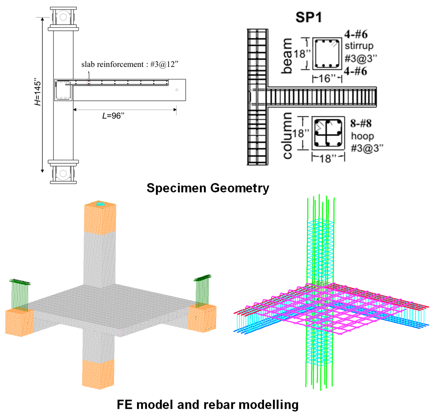
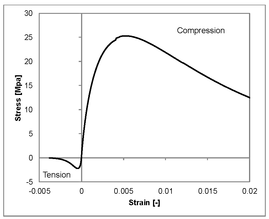
The test data on the response of 3D corner BCJ with slab (specimen ID SP1) reported by Park [37,38] were employed to validate the FE modeling approach in this paper. The specimen geometry and the FE model prepared are shown in Figure 7. The specimen represents a sub-assembly of the 3D corner joint (Figure 3) of an intermediate story of a non-seismically designed RC frame structure. The cross-sectional dimensions of beams framing in both directions were 16” × 18” (406.4 mm × 457.2 mm), and the column cross-section was 18” × 18” (457.2 mm × 457.2 mm). A 6” (152.4 mm) thick slab was cast monolithically with the beam and column. The beams were reinforced longitudinally with 4-#6 (19 mm) bars top and bottom and transversely with #3 (9.5 mm) closed stirrups placed at a spacing of 3” (76 mm). The column was reinforced with 8-#8 (25.4 mm) bars as longitudinal reinforcement and stirrups made using #3 (9.5 mm) bars placed at a spacing of 3” (76 mm). The slab reinforcement consisted of #3 (9.5 mm) bars distributed with a spacing of 12” (304.8 mm) in both directions, top and bottom. In the joint region, no stirrups were provided. The column ends were held in position through bidirectional hinges such that the spacing between the two hinges was 145” (3683 mm). The load was applied close to the free ends of the beams with the distance between the point of loading and column faces as 96” (2438.4 mm). Vertical loads simulating dead loads were applied to the column and the beams. For simulating seismic demand, the bidirectional alternating loading history (Figure 4b) with two sets of cycles at each displacement level was used for the test. The final failure of the specimen was a joint shear failure in both the framing directions. The complete FE model and the reinforcement cage embedded within it are shown in Figure 7. The loads (gravity and seismic) on the column and beam, as in the experiment, were applied in the FE model. Static (gravity) loads were applied as forces, and the bidirectional seismic loads on the beams were applied as per the defined history in terms of displacement in the FE model. In the FE analysis, only one cycle at each displacement level was applied since the computational time was too high given the problem size. The properties of concrete and steel as reported in the experiment were used to define the respective constitutive models in the FE analysis. The stress–strain curve for concrete obtained for the reported material properties is shown in Figure 8. For steel, yield strength of 542 MPa and ultimate strength of 721 MPa were used according to the test data for generating the trilinear stress–strain curve.
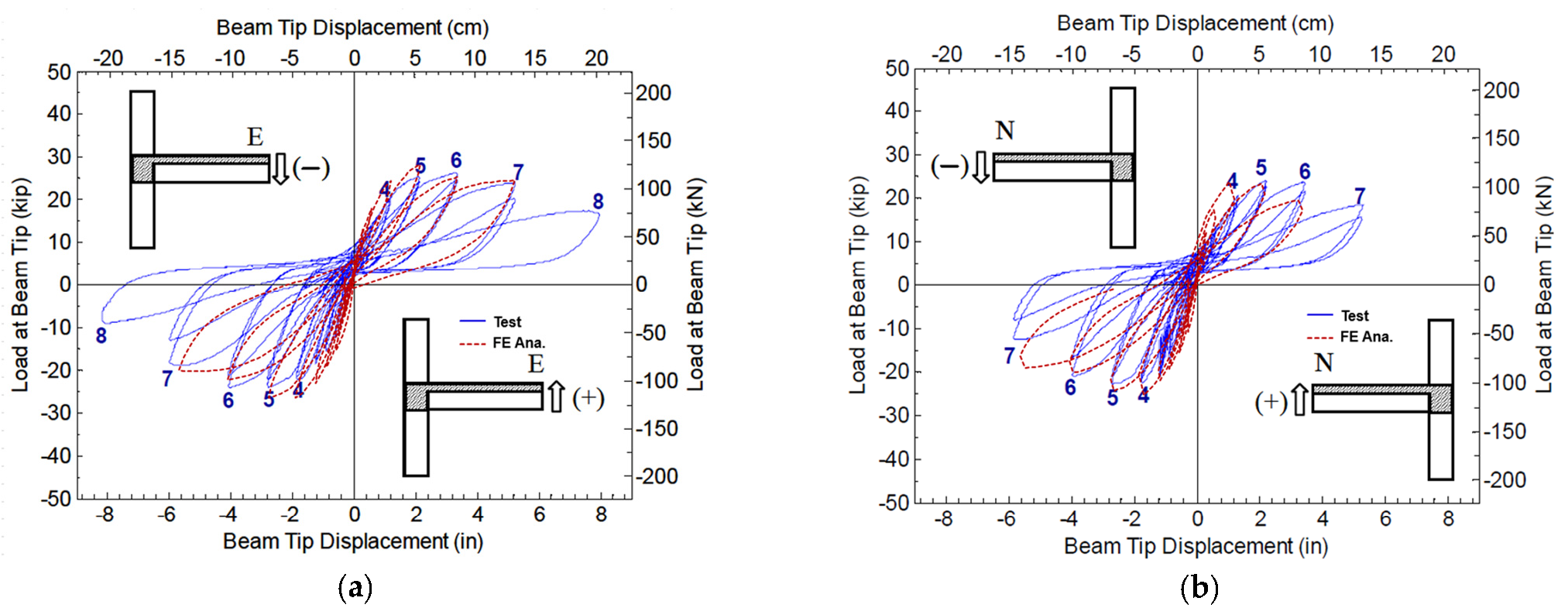
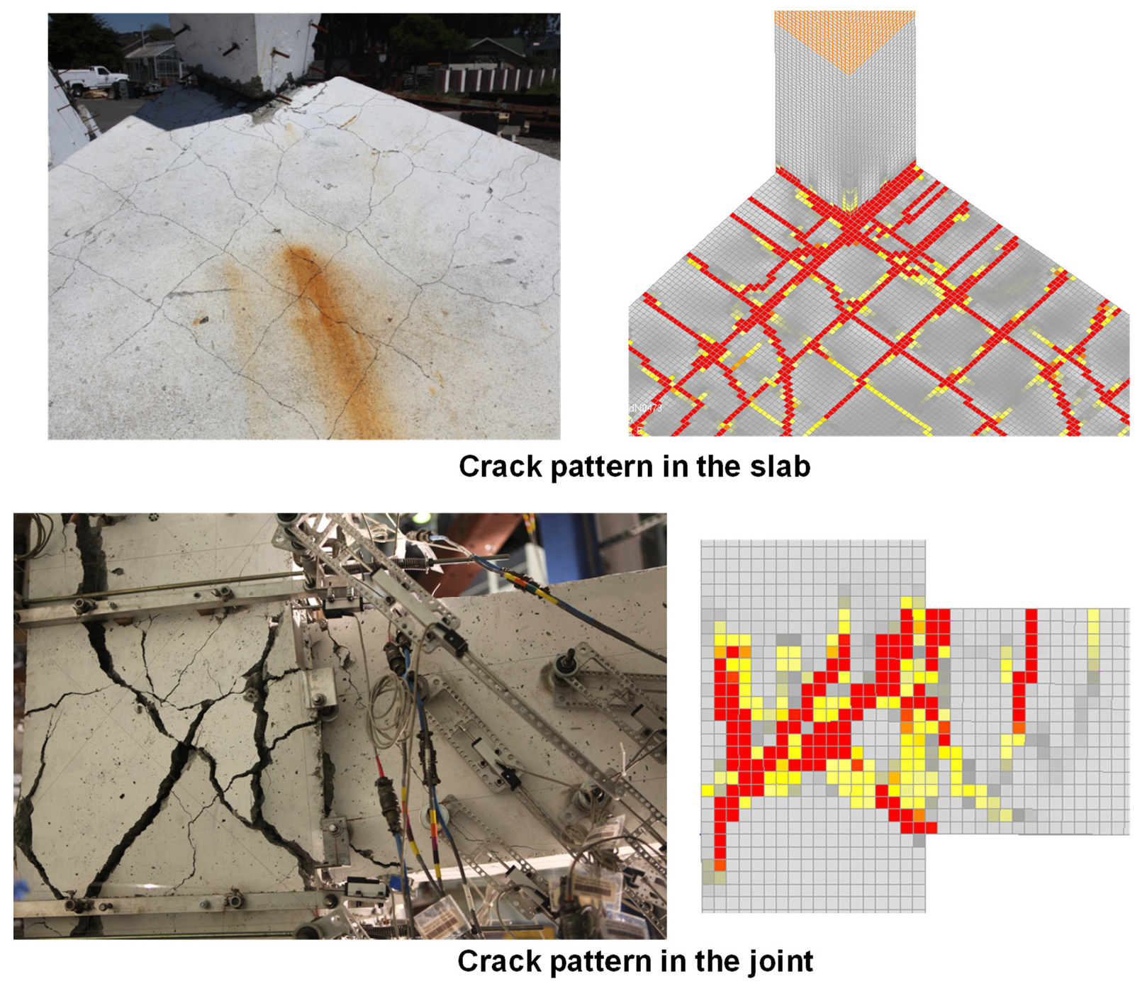
A comparison of load–displacement (hysteretic) behavior reported in the experiment and obtained from the analysis is shown in Figure 9. In Figure 9a, the load applied at the tip of the beam in the E–W direction is plotted against the beam displacement at that location. The FE results are superposed on to the test results for comparison. The corresponding hysteretic loops for the beam framing in the N–S direction are shown in Figure 9b. It can be seen that the FE results compare reasonably well with the test observations. A comparison of failure mode expressed in terms of the crack pattern from the test and the analysis is presented in Figure 10. To visualize the crack patterns in the FE analysis, the contour of principal tensile strains evaluated for elements are plotted. Following the crack band method [43], based on the average element size (25 mm used in the present model in the joint region), an element strain (principal tension) of 0.04 corresponds to the location of the crack of width 1 mm (shown in red). It is seen in Figure 10 that the overall crack pattern as obtained in the FE analysis is in reasonable agreement with the test observation.
Thus, it is seen that the FE modeling approach, as used above, can simulate the behavior of a non-seismically detailed 3D corner BCJ in a reasonably realistic manner. The same model is used further in parametric analyses to understand the influence of different loading scenarios on the response of a 3D corner BCJ with the slab.
5. Parametric FE Studies
As discussed in the previous section, the FE model of the 3D corner joint was used for performing parametric analysis under different loading scenarios. To save on computational time, only monotonic analyses were performed. It is generally well-accepted that the load–displacement response in the case of a monotonic loading corresponds to the envelope of the load–displacement response subjected to cyclic loading. To consider the influence of relative loading in each of the two framing directions (x and y) on the response of the 3D corner BCJ, the following loading cases were considered:
- Unidirectional downwards (X_D; Y_m): In this case, the beam in the x-direction (x-beam) is loaded downwards, and the free end of the beam in the y-direction (y-beam) is kept at its mean position corresponding to applying dead load.
- Unidirectional upwards (X_U; Y_m): The x beam is loaded upwards, and the y beam is maintained at its mean position
- In-phase simultaneous downwards (X_D; Y_D): Both the x and y beams are loaded simultaneously downwards, such that the magnitude and direction of the applied displacement are the same in both the beams at any point in time.
- In-phase simultaneous upwards (X_U; Y_U): Both the x and y beams are loaded simultaneously upwards, such that the magnitude and direction of the applied displacement are the same in both the beams at any point in time.
- Out-of-phase simultaneous (X_U; Y_D): the x-beam is loaded upwards, and the y beam is loaded downwards simultaneously in a way that the upward displacement of the x beam is equal in magnitude to the downward displacement of the y beam at any time.
- Simultaneous 100:50 upwards (X_U; Y_p5U): Both x and y beams are loaded upwards such that at any time, the displacement in the x beam is twice the displacement in the y beam.
- Simultaneous 100:50 downwards (X_D; Y_p5D): Both the x and y beams are loaded downwards such that at any time, the displacement in the x beam is twice the displacement in the y beam.
The unidirectional cases (i and ii) are taken to provide reference values and can be considered physically representing a case in which the earthquake excitation occurs only in the x-direction. The simultaneous in-phase and out of phase cases (iii–v) physically represent a case in which both the framing directions are equally excited during the earthquake. This requires the ground displacement vector to be at 45° to the framing directions. Such an occurrence has a rather low probability. The simultaneous 100:50 cases (vi and vii) represents the case in which earthquake excitation in one framing direction is accompanied by 50% of the excitation in the transverse direction. This is physically closer to the requirement of the present-day provisions, which require consideration of earthquake excitation in the ratio of 100:40:40 for considering the multidirectional effects [51]. The summary of the peak loads obtained from the analysis is given in Table 2.
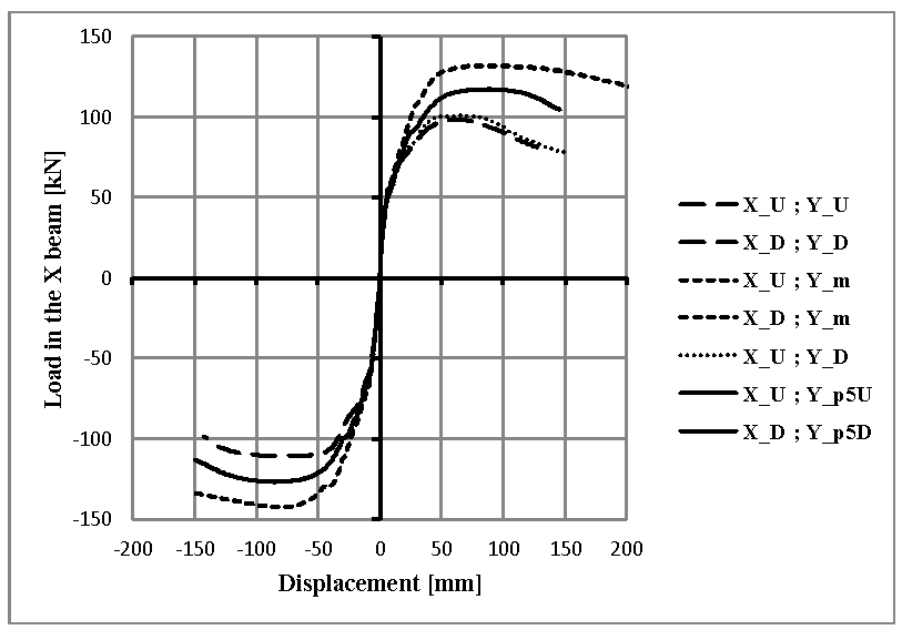
The load–displacement response obtained in each of the above cases is shown in Figure 11. The force applied to the x beam is plotted against the displacement at the point of load application for each of the cases. Downwards displacement and forces are negative, and upwards displacements and forces are positive. The highest capacities were observed for the unidirectional loading cases (i and ii as described above). The capacity for cases with downwards loading was higher than that in the case of upward loading. This is attributed to the fact that the slab contributes as a tension flange, thereby increasing the capacity in the case of loading in a downward direction.
For simultaneous loading cases (iii–v as described above), the detrimental effect of bidirectional loading on the joint capacity was observed to be the highest, resulting in the lowest bound response of the subassembly. Thus, considering the simultaneous application of the design earthquake loads in each of the horizontal directions provides the lowest bound estimates of capacity and imposes the highest possible seismic demand on the BCJ subassembly. However, as discussed earlier, this represents a special and rare case in which earthquake excitation happens at an angle of 45° to the framing directions. Nevertheless, since applying seismic loads in the two framing directions in a simultaneous manner provokes the highest possible demands and the lowest bound of subassembly response, loading histories with simultaneous application of the bidirectional loads (effectively along 45° to the framing direction) are recommended for assessment and design of structural elements of important structures intended to remain operational in the case of major earthquakes.
In general practice, 100% of the design earthquake loading in one framing direction is assumed to be accompanied by approximately 30% or 40% of the design earthquake loading in the other framing direction or by applying the SRSS rule for the directional combination [51]. To investigate the response of BCJ under this type of loading conservatively, the bidirectional 100:50 cases (vi and vii) were considered in the parametric analysis. The response of the BCJ subassembly was found to be intermediate relative to that in the case of unidirectional loading and simultaneous loading. Thus, having the relative magnitudes of loads in the two framing directions in the ratio of 100:50 accounts for the detrimental effect of bidirectional loads, but not as severe as in the case with a ratio of 100:100 of simultaneous loading. Considering the general approach for the directional combination of the applied loads followed in the design codes, a loading protocol accounting for simultaneous loading of two framing directions in the ratio of 100:50 can be considered suitable for the design of joints of general RC structures.
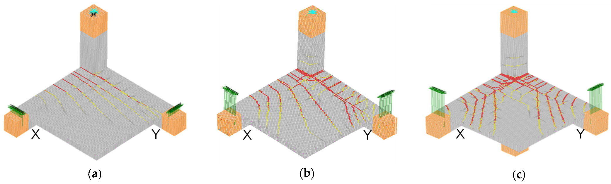
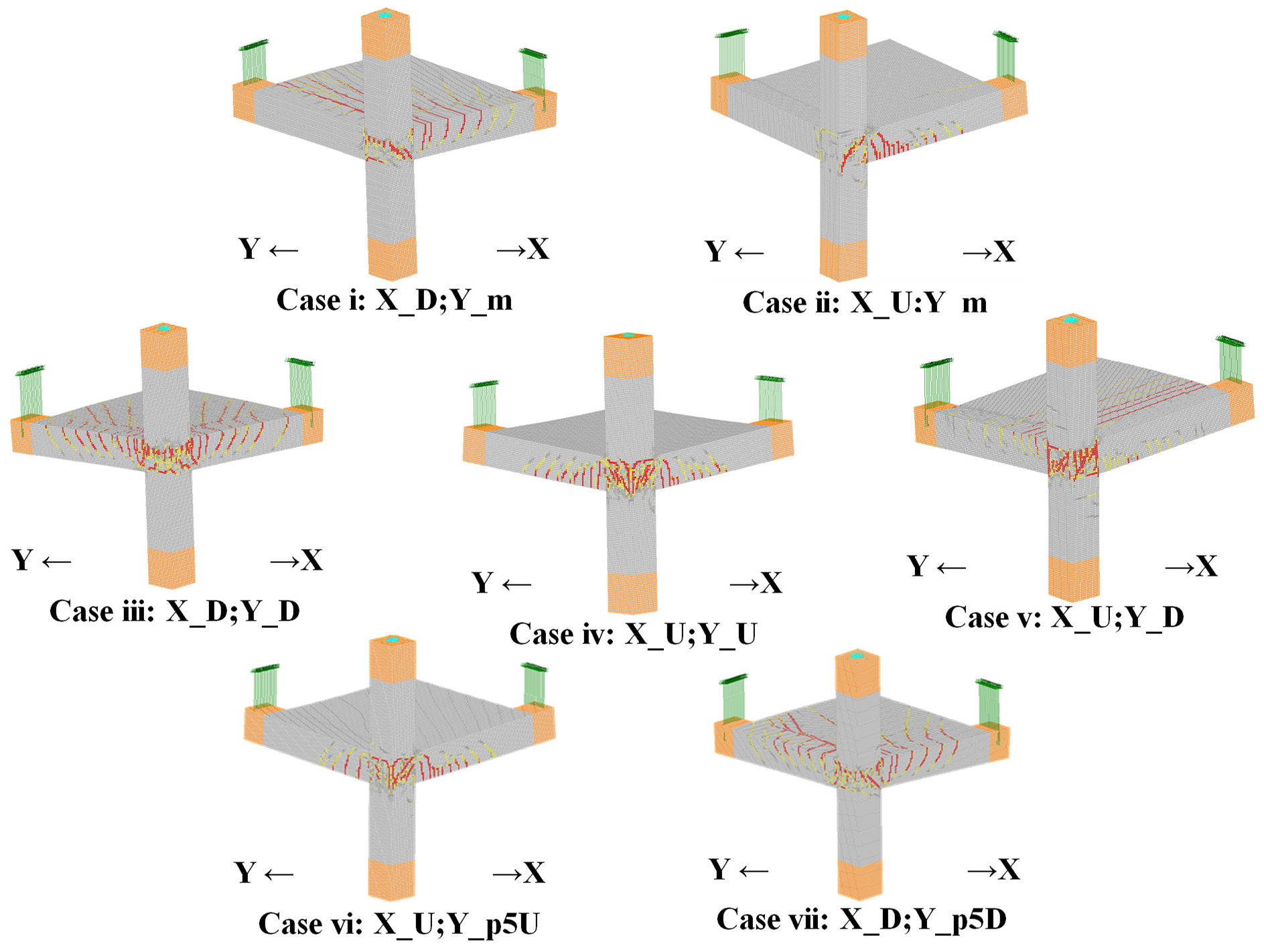
The crack pattern observed on the top surface of the slab in three loading cases (a) X_D; Y_m, (b) X_D; Y_p5D and (c) X_D; Y_D is presented in Figure 12. The relative magnitude of load in the y-direction w.r.t. that in the x-direction is manifested by a distinct change in the crack pattern on the slab top. The crack patterns observed for the joint region for all the parametric cases are presented in Figure 13. As discussed earlier, the visualization of cracks is based on principal strain contours in a manner that red represents a crack width of 1 mm. The observations from the parametric analyses can be summarized in the following points:
- Unidirectional loading or bidirectional alternating loading corresponds to a loading state in which only one framing direction is excited at any given point in time. This case corresponds to the minimum bidirectional interaction. Under this loading case, the slab (see Figure 12a) bears a pattern of cracks transverse to the x-axis. This is an indication of loading action predominantly in the x framing direction. The diagonal joint shear crack, in this case, is observed on the joint face parallel to the x-direction (see Figure 13, cases i and ii).
- Simultaneous loading in both the horizontal directions corresponds to a loading state with maximum bidirectional interaction. Under this loading case, the slab (see Figure 12c) bears a pattern of cracks running at 45° to the horizontal framing direction. This is an indication of bidirectional interaction, which occurs through the connecting slab. Diagonal joint shear cracking of equivalent intensity is observed on joint faces parallel to both x and y-directions (see Figure 13, cases iii–v).
- Simultaneous bidirectional loading in the proportion 100:50 corresponds to a medium-level of bidirectional interaction relative to the above two extremes. This state of loading is quite close to the 100:40 rule of bidirectional loading recommended in the load combination prescribed in the code provisions. The medium effect of bidirectional interaction is reflected in the crack pattern of the slab (see Figure 12b). The diagonal joint shear cracks are more intense on the face parallel to the x-direction than the y-direction (see Figure 13, cases vi and vii).
6. Bidirectional Loading Protocol for BCJ: Discussions
The diversity of loading protocols used for simulation of seismic loading of structural subassembly was discussed at the outset. The available response database under these diverse loading protocols has contributed to the possibility of more thoughtful and rational discussions about the suitability and appropriateness of a particular loading history. The different protocols for bidirectional loading as available in the present state-of-the-art literature were discussed, focusing on the displacement and ductility demands they impose on a structural subassembly. To investigate how different states of loading trigger different response mechanisms in a 3D corner BCJ, the validated FE analysis procedure was used as a tool. It was found that, while unidirectional or bidirectional alternating loading histories trigger the least bidirectional interaction, simultaneous loading histories with 1:1 proportion trigger the maximum bidirectional interaction and hence provide the most conservative estimates of the subassembly response. However, the state of loading corresponds to a rather special and rare case in which the seismic excitation occurs at 45° to the framing direction. Hence, simultaneous loading in the proportion of 100:50 was considered in the parametric analyses and provided an intermediate level of bidirectional interaction. Furthermore, the consideration of simultaneous loading in the proportion of 100:50 closely represents the current manner of considering bidirectional load combination of seismic action following 100–40 rule or SRSS rule. Discussions on the different protocols in Figure 2c and Figure 4 in the framework of the conclusions drawn from the parametric FE analyses are presented here.
The unidirectional (Figure 4a) and the bidirectional alternating (Figure 4b) loading histories represent a loading state in which the seismic excitation occurs along only one of the two framing directions. Under such loading, the bidirectional interaction was found to be the feeblest in the parametric analyses. Hence, to evaluate the bidirectional response of 3D subassemblies, which are supposed to be based on possible bidirectional interaction, these loading histories are not an ideal choice.
The simultaneous loading histories (in-phase: Figure 4c and out-of-phase: Figure 4d) essentially represent the special case in which the seismic excitation occurs at 45° to the framing direction and in a 1:1 proportion. The observations from FE analyses indicated that these loading states impose the maximum bidirectional interaction and are expected to trigger the most conservative response. For important structures, which are required to be operational even in the severest of the earthquakes, evaluating the response of component subassemblies under such loading histories, is recommended.
In the case of the shape-of-8 loading history (Figure 4e), there exists a point of time at which both the framing directions are loaded in the 1:1 proportion. However, the manner of loading is such that at any point in time, loading happens in one of the framing directions only. These histories can be looked upon as a modified version of the bidirectional alternating loading history for consideration of some bidirectional interaction. However, since simultaneous action in both the framing direction never occurs in these loading histories, the bidirectional interactions are not expected to be significant as in the case of simultaneous loading states (1:1 or 100:50).
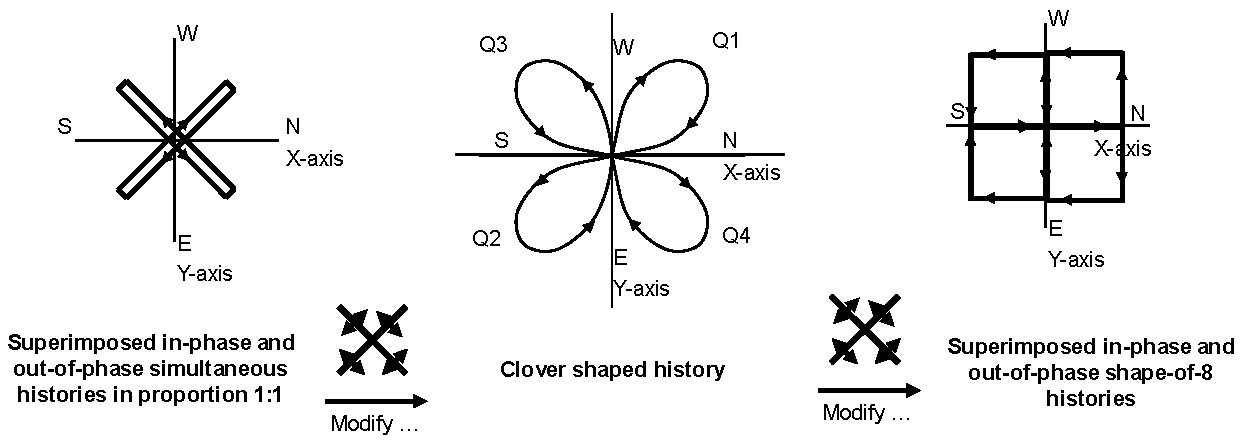
The clover-shaped history (Figure 4f) is a clever solution, which caters to a wide range of proportions of simultaneous bidirectional interactions, varying approximately between 1:0.3 to 1:3.7 at different points of times. It is rather difficult to comment on how the response of a 3D corner BCJ under the clover-shaped history would compare with that under bidirectional simultaneous loading history with equivalent imposed cumulative ductility. Further investigations in this direction are required. However, visualizing the clover-shaped history as a modification of superimposed simultaneous in-phase (Figure 4c) and out-of-phase (Figure 4d) loading histories in the way graphically represented in Figure 14, it shown that one could get to a clover-shaped history by bulging of the diagonals along which loading and unloading are done. Further bulging of the diagonal is seen to result in a loading history, which is a combination of in-phase and out-of-phase shape-of-8 loading histories (Figure 4f). It should be noted that all the three loading histories shown in Figure 14 represent imposed cumulative ductility of , which corresponds to effectively two bidirectional loading cycles at a given displacement level. In this perspective, it is expected that the response of a structural subassembly to a clover-shaped history may not be as critical as in the case of simultaneous bidirectional loading with proportion 1:1. At the same time, the clover-shaped history is expected to consider bidirectional interactions more severely compared to the shape-of-8 loading protocol. It is nevertheless essential to further investigate this topic for a clearer understanding.
The loading history, as recommended by ACI-374.2-R13 [29] (Figure 2c), consists of seismic excitation primarily in one of the framing directions (E–W). There exists a point of loading in the history at which the displacement in the lateral framing directions is in the proportion of 1:1 at 50% of the excitation level. This history also consists of phases in which loading in one direction occurs simultaneously with unloading in the lateral direction (lines at 45° in Figure 2c). However, simultaneous loading of both directions is not considered in this history. Furthermore, two cycles of this history impose lesser cumulative ductility () compared to that () in the case of 2 equivalent cycles of all other bidirectional histories shown in Figure 4. Thus, as seen in the perspective of imposed cumulative ductility, the history recommended by ACI-374.2-R13 [29] is less demanding relative to other bidirectional histories.
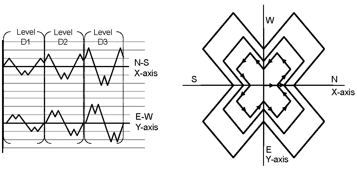
The bidirectional loading histories discussed so far in this paper have primarily been employed by jointers (those who investigate the local subassembly behavior) for evaluation of bidirectional loading interaction in the subassembly. In arriving at these loading histories, triggering the most critical subassembly response has been the governing factor. The representation of the seismic loading considered at the structural level (as worked out by the loaders) is somewhat missing in these histories. At a structural level, for consideration of bidirectional loading, the 100:40 rule is employed. Under this rule, 100% of seismic excitation in one framing direction occurs simultaneously, with 40% of the excitation in the other direction. As explained earlier, the requirement on a rational bidirectional loading history is such that it should trigger the most reasonable yet conservative subassembly response while representing the directional combination of seismic loads considered at the structural level. Since simultaneous excitation of the two framing directions has been observed to trigger the most conservative response, simultaneous loading/unloading of the two framing directions in the proportion of 100:40 represents a rational bidirectional loading protocol. A new bidirectional loading history shown in Figure 15 is proposed in line with these requirements. Three incrementally increasing levels of displacement are represented in a schematic manner. At a given level of displacement, the loading history is such that at any given point of time, the proportion of displacements in the two framing directions is in the range of 1:0 to 1:0.5 or 0:1 to 0.5:1. For a given displacement level, the maximum displacement simultaneously acting in the two framing directions is 75%. Simultaneous loading and unloading of two directions (represented by 45° lines to the axis towards or away from the center) as well as loading in one direction accompanied by unloading in the other (represented by circumferential 45° lines) are considered in this proposed history. The cumulative ductility imposed in one complete set at a given displacement level equal to (4 displacement peaks along each axis), which corresponds to two equivalent bidirectional cycles at the displacement level. The proposed history represents the relative loading of the two framing directions in the proportion of 100:50, which is close to 100:40 as recommended in seismic loading on the structural level. Thus, the proposed loading history represents the seismic loading at the structural level and at the same time considers all possible combinations of loading and unloading actions.
7. Conclusions
The objective of this paper was to investigate the influence of different kinds of loading protocols on the seismic behavior of 3D beam–column joints and to arrive at a loading protocol for reasonable consideration of bidirectional interaction in structural sub-assemblies. The major conclusions are as follows:
- In an extensive literature survey, available information on the response of RC structural sub-assemblies subjected to different loading histories is explored in this paper. The diversity of the available loading histories has provided for a more thoughtful and rational discussion related to their influence on the subassembly response;
- It is observed that in the framework of the imposed displacement and ductility and the response of structural subassembly under different loading scenario, it is possible to rationally compare the various available bidirectional loading protocols;
- FE analyses are used as a tool to study the response of the 3D corner BCJ subassembly under different loading scenario, which facilitated the discussions related to comparison of different available loading protocols;
- The parametric studies highlighted that the available protocols were focused primarily on triggering the most critical response in the subassembly. The representation of seismic loading at the structural level was somewhat missing;
- A proposal for bidirectional loading of BCJ subassemblies is presented, which represents the seismic loading on the structural level reasonably and at the same time conservatively considers the seismic behavior of the subassembly.
This paper intends not to decide which loading history is correct or not correct but rather to provide for more thoughtful consideration of each loading history. The authors hope that the information provided in this paper will help researchers in selecting suitable seismic loading protocols for their investigations.
Author Contributions
Conceptualization, V.M. and A.S.; methodology, V.M. and A.S.; finite element investigation, V.M.; writing—original draft preparation, V.M.; writing—review and editing, V.M. and A.S.; visualization, V.M. All authors have read and agreed to the published version of the manuscript.
Funding
This research received no external funding.
Conflicts of Interest
The authors declare no conflict of interest.
References
- Higashi, Y.; Ohkubo, M.; Ohtsuka, M. Influences of loading excursions on restoring force characteristics and failure modes of reinforced concrete columns. In Proceedings of the 6th World Conference of Earthquake Engineering, New Delhi, India, 10–14 January 1977. [Google Scholar]
- Jirsa, J.O. Behavior of elements and subassemblages-RC Frames. In Workshop on Earthquake Resistant Reinforced Concrete Building Construction; University of California: Berkeley, CA, USA, 1977. [Google Scholar]
- Park, R.; Hopkins, D.C. Unites States/New Zealand/Japan/China collaborative research project on the seismic design of beam-column-slab joints. Bull. N. Z. Natl. Soc. Earthq. Eng. 1989, 22, 122–127. [Google Scholar]
- Hanson, N.W.; Connor, H.W. Seismic Resistance of Reinforced Concrete Beam-Column Joints. J. Struct. Div. 1967, 93, 533–560. [Google Scholar] [CrossRef]
- Durrani, A.J.; Wight, J.K. Experimental and Analytical Study of Internal Beam to Column Connections Subjected to Reversed Cyclic Loading; Report No UMEE 82R3; The University of Michigan: Ann Arbor, MI, USA, 1982. [Google Scholar]
- Ehsani, M.R.; Wight, J.K. Behavior of External Reinforced Concrete Beam Column Connections Subjected to Earthquake Type Loading; University of Michigan: Ann Arbor, MI, USA, 1982. [Google Scholar]
- Hamil, S.J. Reinforced Concrete Beam-Column Connection Behaviour. Ph.D. Thesis, School of Engineering, University of Durham, Durham, UK, 2000. [Google Scholar]
- Beres, A.; White, R.; Gergely, P. Seismic Behavior of Reinforced Concrete Frame Structures with Nonductile Details; National Center for Earthquake Engineering Research: New York, NY, USA, 1992. [Google Scholar]
- Pantelides, C.P.; Hansen, J.; Nadauld, J.; Reaveley, L.D. Assessment of Reinforced Concrete Building Exterior Joints with Substandard Details; PEER Report; Pacific Earthquake Engineering Research Center: Berkeley, CA, USA, 2002. [Google Scholar]
- Sharma, A.; Reddy, G.; Vaze, K.; Ghosh, A.; Kushwaha, H. Experimental Investigations and Evaluation of Strength and Deflections of Reinforced Concrete Beam-Column Joints Using Nonlinear Static Analysis; Bhabha Atomic Research Centre: Mumbai, India, 2009. [Google Scholar]
- Choi, H.-K.; Choi, Y.-C.; Choi, C.-S. Development and testing of precast concrete beam-to-column connections. Eng. Struct. 2013, 56, 1820–1835. [Google Scholar] [CrossRef]
- Paulay, T.; Park, R. Joints in Reinforced Concrete Frames Designed Earthquake Resistance. In U.S. N.Z.-Japan Seminar Report; Bulletin of the New Zealand Society for Earthquake: Wellington, New Zealand, 1984. [Google Scholar]
- Kurose, Y. Recent Studies on Reinforced Concrete Beam-Column Joints in JAPAN; Report No.87-8; Phil M. Ferguson Structural Engineering Laboratory, The University of Texas at Austin: Austin, TX, USA, 1987. [Google Scholar]
- McKay, G.R. The observed effects of cyclic loading of an unreinforced concrete internal beam-column joint. In Proceedings of the 3rd US-N Z-Japan Seminar, Christchurch, New Zealand, 10–12 August 1987. [Google Scholar]
- Cheung, P.C.; Paulay, T.; Park, R. A Reinforced Concrete Beam-Column Joint of a Prototype One-Way Frame with Floor Slab Designed for Earthquake Resistance; Research Report; Department of Civil Engineering, University of Canterbury: Christchurch, New Zealand, 1987. [Google Scholar]
- Kurose, Y.; Jirsa, J.O. Proceedings of the Seminar on Reinforced Concrete High-Rise Buildings in Japan With Special Concern on Aseismic Design of Beam-Column Joints; Report No. 87-05; Phil M. Ferguson Structural Engineering Laboratory, The University of Texas at Austin: Austin, TX, USA, 1987. [Google Scholar]
- Kurose, Y.; Guimaraes, G.N.; Lui, Z.; Kreger, M.E.; Jirsa, J.O. Study of Reinforced Concrete Beam Column Joints under Uniaxial and Biaxial Loading; Report No.88-2; Phil M. Ferguson Structural Engineering Laboratory, The University of Texas at Austin: Austin, TX, USA, 1988. [Google Scholar]
- Guimaraes, G.N. Reinforced Concrete Frame Connections Constructed Using High Strength Materials. Ph.D. Thesis, University of Texas at Austin, Austin, TX, USA, 1988. [Google Scholar]
- French, C.W.; Boroojerdi, A. Contribution of R/C Floor Slabs in Resisting Lateral Loads. J. Struct. Eng. 1989, 115, 1–18. [Google Scholar] [CrossRef]
- Cheung, P.C.; Paulay, T.; Park, R. Interior and Exterior Reinforced Concrete Beam-Column Joints of a Prototype Two-Way Frame with Floor Slab Designed for Earthquake Resistance; Research Report; Department of Civil Engineering, University of Canterbury: Christchurch, New Zealand, 1989. [Google Scholar]
- Genesio, G. Seismic Assessment of RC Exterior Beam-Column Joints Retrofitted with Haunches Using Post-Installed Anchors. Ph.D. Thesis, Institut für Werkstoffe im Bauwesen, Universität Stuttgart, Stuttgart, Germany, 2012. [Google Scholar]
- Li, B.; Tran, C.T.N.; Pan, T.-C. Experimental and Numerical Investigations on the Seismic Behavior of Lightly Reinforced Concrete Beam-Column Joints. J. Struct. Eng. 2009, 135, 1007–1018. [Google Scholar] [CrossRef]
- Shin, M.; LaFave, J.M. Seismic performance of reinforced concrete eccentric beam-column connections with floor slabs. ACI Struct. J. 2004, 101, 403–412. [Google Scholar]
- Goto, Y.; Joh, O. Shear resistance of RC interior eccentric beam-column joints. In Proceedings of the 13th World Conference on Earthquake Engineering, Vancouver, BC, Canada, 1–6 August 2004. [Google Scholar]
- Shin, M.; LaFave, J. Reinforced concrete edge beam—column—slab connections subjected to earthquake loading. Mag. Concr. Res. 2004, 56, 273–291. [Google Scholar] [CrossRef]
- Aycardi, L.E.; Mander, J.B.; Reinhorn, A.M. Seismic Resistance of Reinforced Concrete Frame Structures Designed Only for Gravity Loads-Part II: Experimental Performance of Subassemblages; Technical Report No. NCEER-92-0028; National Center for Earthquake Engineering Research: Buffalo, NY, USA, 1992. [Google Scholar]
- ACI-374.1-05. Acceptance Criteria for Moment Frames Based on Structural Testing and Commentary (ACI 374.1-05); American Concrete Institute: Farmington Hills, MI, USA, 2005. [Google Scholar]
- ACI-318-19. Building Code Requirements for Structural Concrete (ACI 318-19) and Commentary (ACI 318R-19); American Concrete Institute: Farmington Hills, MI, USA, 2019. [Google Scholar]
- ACI-374.2-R-13. Guide for Testing Reinforced Concrete Structural Elements under Slowly Applied Simulated Seismic Loads; Reported by ACI committee 374; American Concrete Institute: Farmington Hills, MI, USA, 2013. [Google Scholar]
- FEMA-461. Interim Testing Protocols for Determining the Seismic Performance Characteristics of Structural and Nonstructural Components; Federal Emergency Management Agency: Washington, DC, USA, 2007. [Google Scholar]
- Burguieres, S.T.; Jirsa, J.O.; Longwell, J.E. The behaviour of beam column joints under bidirectional load reversals. In AICAP-CEB Symposium on Structural Concrete under Seismic Actions; CEB Symposium Rome; Comite Euro-International du Beton: Paris, France, 1979. [Google Scholar]
- Longwell, J.E. A Comparative Study of Biaxially Loaded Reinforced Concrete Beam-Column Joints. Master’s Thesis, The University of Texas at Austin, Austin, TX, USA, 1980. [Google Scholar]
- Burguieres, S.T.; Longwell, J.E.; Jirsa, J.O. Shear and Bond Deterioration in Beam Column Joints under Bidirectional Load Reversals. 1980. [Google Scholar]
- Leon, R.; Jirsa, J.O. Bidirectional Loading of R.C. Beam-Column Joints. Earthq. Spectra 1986, 2, 537–564. [Google Scholar] [CrossRef]
- Kam, W.; Quintana Gallo, P.; Akguzel, U.; Pampanin, S. Influence of Slab on the Seismic Response of Sub-Standard detailed Exterior Reinforced Concrete Beam Column Joints; University of Canterbury, Civil and Natural Resources Engineering: Christchurch, New Zealand, 2010. [Google Scholar]
- Akguzel, U. Seismic Performance of FRP Retrofitted Exterior Beam-Column Joints under Varying Axial and Bidirectional Load-Ing. Ph.D. Thesis, Department of Civil and Natural Resources Engineering, University of Canterbury, Christchurch, New Zealand, 2011. [Google Scholar]
- Park, S.; Mosalam, K.M. Experimental and Analytical Studies on Reinforced Concrete Buildings with Seismically Vulnerable Beam-Column Joints; Pacific Earthquake Engineering Research Center, College of Engineering, University of California, Berkeley: Berkeley, CA, USA, 2012. [Google Scholar]
- Park, S. Experimental and Analytical Studies on Old Reinforced Concrete Buildings with Seismically Vulnerable Beam-Column Joints. Ph.D. Thesis, University of California, Berkeley, Berkeley, CA, USA, 2010. [Google Scholar]
- Park, R.; Paulay, T. Reinforced Concrete Structures; Wiley: Hoboken, NJ, USA, 1975. [Google Scholar]
- Sharma, A. Seismic Behavior and Retrofitting of RC Frame Structures with Emphasis on Beam-Column Joints: Experiments and Numerical Modeling. Ph.D. Thesis, Institut für Werkstoffe im Bauwesen, Universität Stuttgart, Stuttgart, Germany, 2013. [Google Scholar]
- Ozbolt, J. Masa 3: Finite Element Program for 3D Nonlinear Analysis of Concrete and Reinforced Concrete Structures; University of Stuttgart: Stuttgart, Germany, 2010. [Google Scholar]
- Ožbolt, J.; Li, Y.; Kožar, I. Microplane model for concrete with relaxed kinematic constraint. Int. J. Solids Struct. 2001, 38, 2683–2711. [Google Scholar] [CrossRef]
- Bažant, Z.P.; Oh, B.H. Crack band theory for fracture of concrete. Mater. Struct. 1983, 16, 155–177. [Google Scholar] [CrossRef] [Green Version]
- Lettow, S. Bond Element for Nonlinear Finite Element Analysis-Application to Lap Splices. Ph.D. Thesis, Institut für Werkstoffe im Bauwesen, Universität Stuttgart, Stuttgart, Germany, 2006. [Google Scholar]
- Bruckner, M.J. Application of Headed Reinforcement in Frame-Corners, Beam Column Joints and Column-Foundation-Connections. Ph.D. Thesis, Institut für Werkstoffe im Bauwesen, Universität Stuttgart, Stuttgart, Germany, 2007. (In German). [Google Scholar]
- Sharma, A.; Genesio, G.; Reddy, G.; Eligehausen, R. Nonlinear dynamic analysis using microplane model for concrete and bond slip model for prediction of behavior of nonseismically detailed RCC beam-column joints. J. Struct. Eng. 2009, 36, 250–257. [Google Scholar]
- Herzog, M.B. Contribution on the Harmonization of Design in Reinforced Concrete Construction and Fastening Technology. Ph.D. Thesis, Institut für Werkstoffe im Bauwesen, Universität Stuttgart, Stuttgart, Germany, 2015. (in German). [Google Scholar]
- Mahadik, V.; Sharma, A.; Hofmann, J. Re-evaluation of existing tests on RC connections using post-installed reinforcing bars. Eng. Struct. 2020, 209, 109970. [Google Scholar] [CrossRef]
- Mahrenholtz, C. Seismic Bond Model for Concrete Reinforcement and the Application to Column-to-Foundation Connections. Ph.D. Thesis, Institut für Werkstoffe im Bauwesen, Universität Stuttgart, Stuttgart, Germany, 2012. [Google Scholar]
- Chellapandian, M.; Prakash, S.S.; Mahadik, V.; Sharma, A. Experimental and Numerical Studies on Effectiveness of Hybrid FRP Strengthening on Behavior of RC Columns under High Eccentric Compression. J. Bridg. Eng. 2019, 24, 04019048. [Google Scholar] [CrossRef]
- Sesigur, H.; Celik, O.C.; Cili, F. Review and evaluation of combination rules for structures under bi-directional earthquake excitations. In Proceedings of the 13th World Conference on Earthquake Engineering, Vancouver, BC, Canada, 1–6 August 2004. [Google Scholar]
Figure 1.
Loading protocol used by Hanson and Connor [4].
Figure 1.
Loading protocol used by Hanson and Connor [4].

Figure 2.
Recommended loading protocols for seismic evaluation in guidelines: (a) ACI-374.1-05 [27] loading sequence, (b) ACI-374.2-R13 [29] recommendation, (c) bidirectional loading sequence as per ACI-374.2-R13 [29].

Figure 3.
Beam–column joint configurations possible in the middle story of a 3D RC frame.

Figure 4.
Possible protocols (schematic) for bidirectional loading of BCJs: (a) unidirectional loading, (b) bidirectional alternating, (c) bidirectional simultaneous (XY in-phase), (d) bidirectional simultaneous (XY out of-phase) (e) bidirectional shape-of-8 (f) bidirectional cloverleaf shaped.
Figure 4.
Possible protocols (schematic) for bidirectional loading of BCJs: (a) unidirectional loading, (b) bidirectional alternating, (c) bidirectional simultaneous (XY in-phase), (d) bidirectional simultaneous (XY out of-phase) (e) bidirectional shape-of-8 (f) bidirectional cloverleaf shaped.

Figure 5.
Load transfer mechanism in 2D beam–column joint sub-assembly.

Figure 6.
Orientation of the diagonal failure plane for different bidirectional loading cases.


Figure 8.
Stress–strain curve for concrete used for FE analysis.

Figure 9.
Comparison of load–displacement curves obtained from FE analysis with test observation (a) E–W direction, (b) N–S direction.
Figure 9.
Comparison of load–displacement curves obtained from FE analysis with test observation (a) E–W direction, (b) N–S direction.

Figure 10.
Comparison of crack patterns evaluated in FE analysis with the test observations.

Figure 11.
Load displacement results were obtained from parametric FE analyses.

Figure 12.
Crack pattern on the slab for different loading scenario (a) X_D; Y_m, (b) X_D; Y_p5D, (c) X_D; Y_D.
Figure 12.
Crack pattern on the slab for different loading scenario (a) X_D; Y_m, (b) X_D; Y_p5D, (c) X_D; Y_D.

Figure 13.
Crack pattern at the joint in all the parametric cases.

Figure 14.
Graphical visualization of clover-shaped history.

Figure 15.
Proposal for a rational bidirectional loading protocol.


Table 1.
Imposed displacement and cumulative ductility in one cycling set at a given displacement level.
Table 1.
Imposed displacement and cumulative ductility in one cycling set at a given displacement level.
| Loading Type | Displacement Imposed | Cumulative Ductility | |||
|---|---|---|---|---|---|
| N–S axis | E–W axis | N–S:E–W | Rel. Max. N–S = E–W | ||
| Unidirectional | 0 | 1:0 | 0 | ||
| Bidirectional alternating | 1:0/0:1 | 0 | |||
| Bidirectional simultaneous in-phase | 1:1 | 1 | |||
| Bidirectional simultaneous out-of-phase | 1:−1 | 1 | |||
| Bidirectional shape of 8 in-phase | 1:1 | 1 | |||
| Bidirectional shape of 8 out-of-phase | 1:−1 | 1 | |||
| Bidirectional clover-shaped | 1:±0.58 | 0.94 | |||
| Bidirectional ACI-374.2-R13 [29] | 1:0 | 0.5 | |||
Table 2.
Summary of results obtained for different cases considered in the parametric analysis.
| Sl. No | Nomenclature | Rel. Px | Rel. Py | Direction | Ultimate Load x Beam (kN) |
|---|---|---|---|---|---|
| (i) | X_D; Y_m | −1 | 0 | x-DOWN | 142.5 |
| (ii) | X_U; Y_m | 1 | 0 | x-UP | 131.8 |
| (iii) | X_D; Y_D | −1 | −1 | x and y DOWN | 110.7 |
| (iv) | X_U; Y_U | 1 | 1 | x and y UP | 98.5 |
| (v) | X_U; Y_D | 1 | −1 | x-UP and y-DOWN | 100.9 |
| (vi) | X_U; Y_p5U | 1 | 0.5 | x and y UP | 117.5 |
| (vii) | X_D; Y_p5D | −1 | −0.5 | x and y DOWN | 126.7 |
Publisher’s Note: MDPI stays neutral with regard to jurisdictional claims in published maps and institutional affiliations. |
© 2021 by the authors. Licensee MDPI, Basel, Switzerland. This article is an open access article distributed under the terms and conditions of the Creative Commons Attribution (CC BY) license (https://creativecommons.org/licenses/by/4.0/).
Share and Cite
MDPI and ACS Style
Mahadik, V.; Sharma, A. Bidirectional Loading History for Seismic Testing of 3D Frame Joints. CivilEng 2021, 2, 349-369. https://0-doi-org.brum.beds.ac.uk/10.3390/civileng2020019
AMA Style
Mahadik V, Sharma A. Bidirectional Loading History for Seismic Testing of 3D Frame Joints. CivilEng. 2021; 2(2):349-369. https://0-doi-org.brum.beds.ac.uk/10.3390/civileng2020019
Chicago/Turabian StyleMahadik, Vinay, and Akanshu Sharma. 2021. "Bidirectional Loading History for Seismic Testing of 3D Frame Joints" CivilEng 2, no. 2: 349-369. https://0-doi-org.brum.beds.ac.uk/10.3390/civileng2020019