
Anchor Plates Bonded on Reinforced Concrete: A Preliminary Experimental Investigation


Department of Civil and Environmental Engineering, Politecnico di Milano, P.zza Leonardo da Vinci, 32, 20133 Milan, Italy
*
Author to whom correspondence should be addressed.
CivilEng 2021, 2(2), 385-395; https://0-doi-org.brum.beds.ac.uk/10.3390/civileng2020021
Submission received: 26 February 2021
/
Revised: 23 April 2021
/
Accepted: 15 May 2021
/
Published: 19 May 2021
(This article belongs to the Special Issue Connections in Concrete)
Abstract
:During the last decades, different technologies to anchor steel elements in concrete were proposed. The present work presents the results of a preliminary investigation of a new connection characterized by single steel plates that are directly bonded on concrete surfaces. The anchor response was experimentally investigated under both tension and shear actions. Specific conditions influencing the behavior of the bonded assembly were discussed, with particular reference to the presence of cracks and crack cycling in concrete.
1. Introduction
Nowadays, thinking about energy production is a synonym of thinking about how to produce more energy with less input. The solution to this complex equation is the life extension of the existing facilities as per nuclear ones. Hence, the nuclear industry has been looking for non-intrusive and medium-duty fasteners to enable the maintenance of existing assets while saving time and reducing operational costs.
Under such a perspective, a solution consists in adopting surface-bonded connection; plates or additional reinforcement can be bonded by an adhesive to hardened concrete. In general, bonding steel plates to reinforced concrete element was investigated as supplementary bending [1] or shear [2] reinforcement, also focusing on the influence of glued plates on stiffness, cracking, and ultimate capacity of strengthened members [3].
However, to the authors’ knowledge, no public result is currently available regarding bonded plates used to transfer tensile or shear actions from an attached element to a reinforced concrete element.
In this frame of work, COLD PAD and Électricité de France (EDF) co-developed and patented a non-intrusive composite and fastener bonded “on” concrete rather “in” concrete, called C-BLOCKTM. This innovative fastener should be used for permanent applications.
This paper presents the results of a first exploratory test campaign performed by COLD PAD and EDF jointly with Politecnico di Milano, discussing the potentiality of such a fastening technique.
2. Materials and Methods
2.1. Test Specimens
Three different specimens with the same plate geometry (Figure 1) but different interface geometries (Figure 2) were considered:
- Type A: steel fastener with no intermediate deformation layer (IDL);
- Type B: steel fastener with a simple IDL;
- Type C: steel fastener with a cellular IDL.
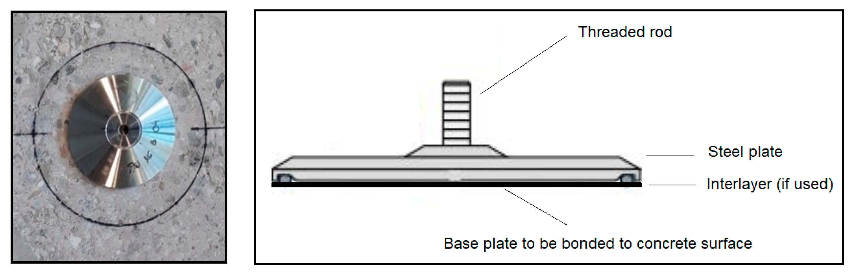
Figure 1.
Example of C-BlockTM bonded on concrete.

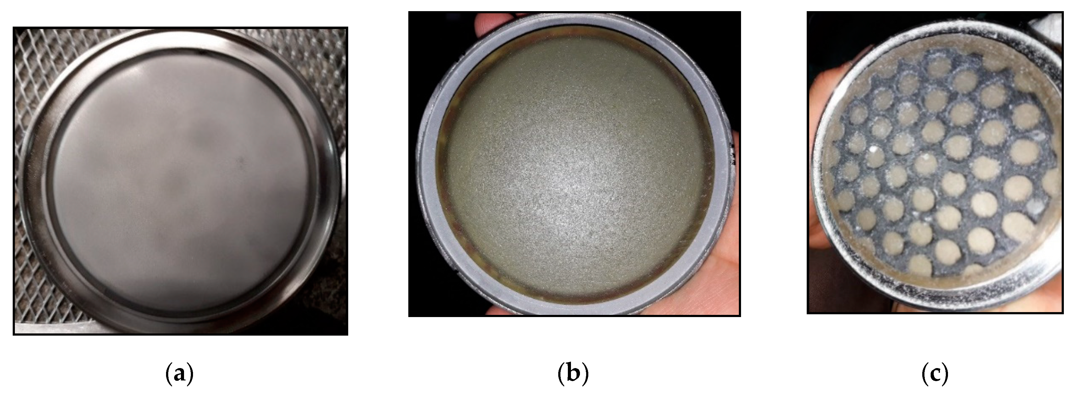
Figure 2.
Bottom side of the steel platess: (a) type A with no intermediate deformation layer (IDL); (b) type B with a simple IDL; (c) type C with a cellular IDL.
Figure 2.
Bottom side of the steel platess: (a) type A with no intermediate deformation layer (IDL); (b) type B with a simple IDL; (c) type C with a cellular IDL.

The three types of fasteners had an overall circular footprint of 120 mm in external diameter. Their thicknesses were 20 mm for type A fastener and 23 mm for types B and C fasteners. A threaded rod M12 with a height of 10 mm protruded from each plate. It should be noted that two different materials for steel parts were considered during this campaign (see Table 1). Specimens made of stainless steel or high-strength steel (HSS) were hereinafter identified by lowercase or uppercase letters, respectively.
The bottom sides of the steel plates reported in Figure 2 were bonded on concrete with an epoxy resin currently available on the market (HIT-RE 500 V3) and using a special tool developed by COLD PAD (based in Paris, France) and named C-HAWK (Figure 3). The function of such a kit was to heat the anchor and the concrete surface to accelerate the curing process. As preliminary activities, on the casting side of the concrete specimen, the surface was sanded with a grinding wheel and cleaned by compressed air to remove fragments of the concrete before applying the bonding agent.
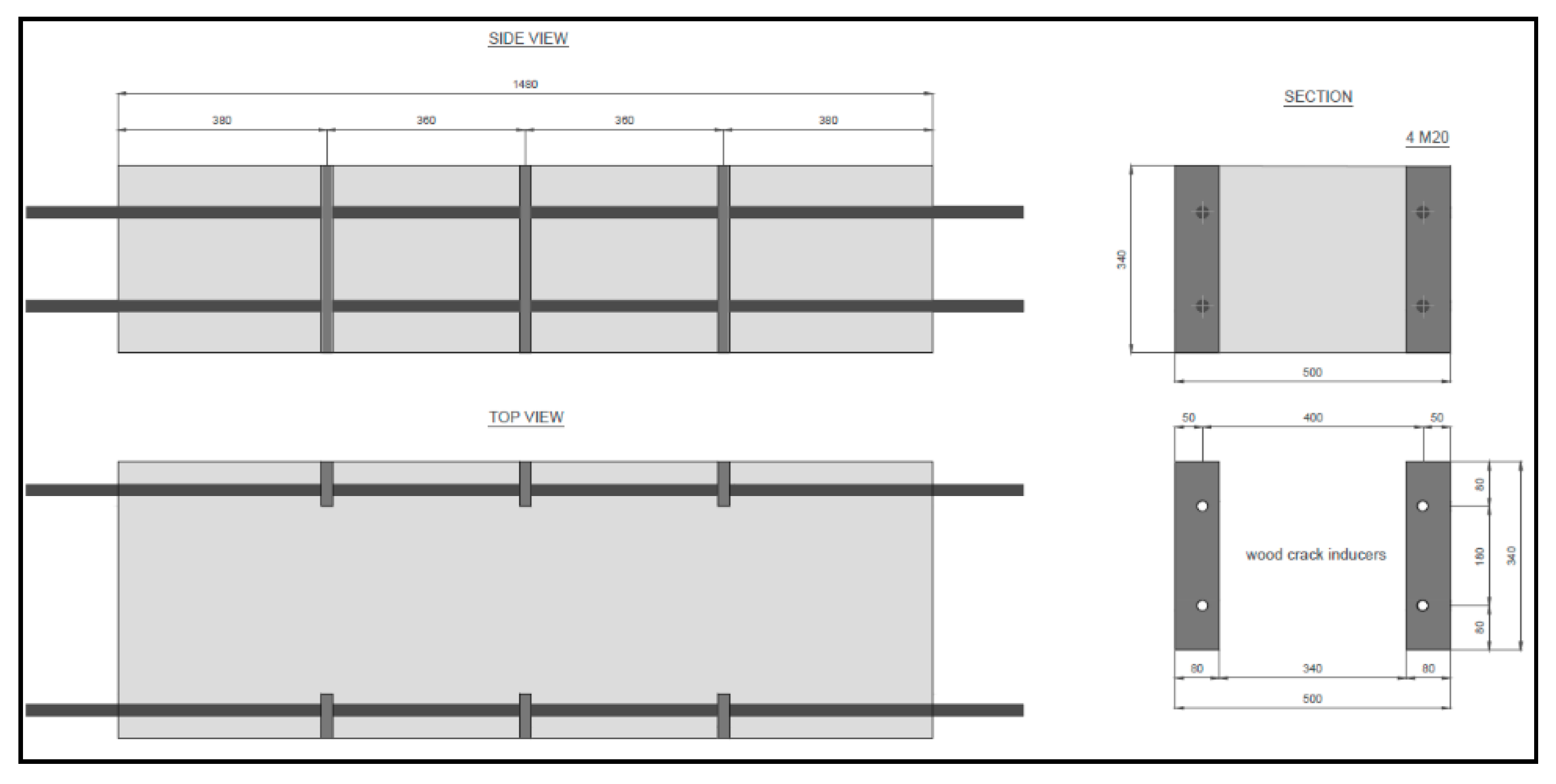
Concrete slabs dimensions were 1440 mm × 500 mm × 330 mm. Four longitudinal M20 bars were used as reinforcement for tests in cracked and non-cracked concrete (Figure 4). Threaded rods were in class 8.8 according to EN ISO 898-1 [4]. The longitudinal sections of the specimens are reported in Figure 4.
The geometrical dimensions of the concrete specimen, the spacing and edge distances of the bars, the spacing of the crack inducers, the steel grade, and the amount of reinforcement were selected in order to ensure a maximum crack opening equal to 1.0 mm while avoiding the splitting of the specimens.
The concrete mix was designed for (Eurocode 2 [5]) C20/25 class by adopting round aggregate and CEM II 52.5. The mix components are reported in Table 2. After casting, the specimens were stored at room temperature by avoiding direct sunlight exposure and by keeping the cast surface wet.
The mechanical characteristics of the concrete were tested according to EN 12390-3 [6] on cubes (side: 150 mm). For each slab, at least three tests were carried out. The average value of the compressive strength for the tested batch at the time of testing was equal to 33.5 MPa.
2.2. Test Program and Research Significance
The test program is reported in Table 3, where:
- −
- –
- N and V indicate tensile and shear actions, respectively;
- –
- Types a/b/c were related to 316 L stainless steel;
- –
- Types A/B/C were related to HSS.

Table 3.
Test program.
| Test Code | Description | Crack Width Δw (mm) | Load Direction | Type a | Type b | Type c | Type A | Type B | Type C |
|---|---|---|---|---|---|---|---|---|---|
| A1 | Reference tension tests in uncracked concrete | 0.0 | N | 1 | - | 1 | - | 1 | - |
| A5 | Reference shear test in uncracked concrete | 0.0 | V | 1 | 1 | 1 | - | - | - |
| C2.1a | Reference tension tests in cracked concrete | 0.8 | N | 2 | 1 | - | - | 1 | 2 |
| C2.2 | Reference shear test in cracked concrete | 0.8 | V | - | - | - | 1 | 1 | 1 |
| C2.5 | Functioning with tension load under varying crack width | 0.1 ÷ 0.8 | N | - | - | 1 | 2 | 2 | 1 |
The test program was not drafted for the scope of determining capacities of the investigated cases for which the numbers of test repetitions were very low, but in the framework of a preliminary investigation for the scope of addressing the following questions:
- Is the proposed technique effective in transferring loads to the concrete member?
- Is there an influence of the interlayer on such a mechanism?
- Is the system sensitive to cracks?
Results will consequently be presented and discussed from this perspective, noticing how 6 tests were carried out in uncracked concrete, 9 tests were performed in cracked concrete with static crack, and 6 tests were conducted in cracked concrete under crack-cycling conditions. In total, 7 tests were carried out for each of the three investigated interlayer conditions.
2.3. Test Apparati and Procedures
For testing in both cracked and non-cracked concrete, the external force was applied to an anchor by adopting different apparati in case of shear and tension loading.
For testing in cracked concrete, the crack opening was induced after having installed and having reached the full hardening of the bonding agent, which was strictly product-dependent.
Such procedures differ from the one typically adopted to test anchors bonded-in concrete. In fact, when the anchor is installed in the concrete, it may act as crack inducers when the concrete member is loaded. Consequently, testing procedures [7,8] requires that crack opening precedes anchor installation. In the current cases, differently, no hole was carried out in concrete which may lead to stress concentrations and to the conservative assumption that a crack passes through the anchor axis. No other deviation was adopted with respect to EAD 330499 [7] and TR049 [8], taken as references for the boundary conditions and the loading protocols.
As for loading rates, anchor loading was carried out by increasing the stroke displacement at 0.048 mm/s, and crack cycling was carried out at 0.2 Hz.
Some specific details regarding the test apparati are provided hereinafter.
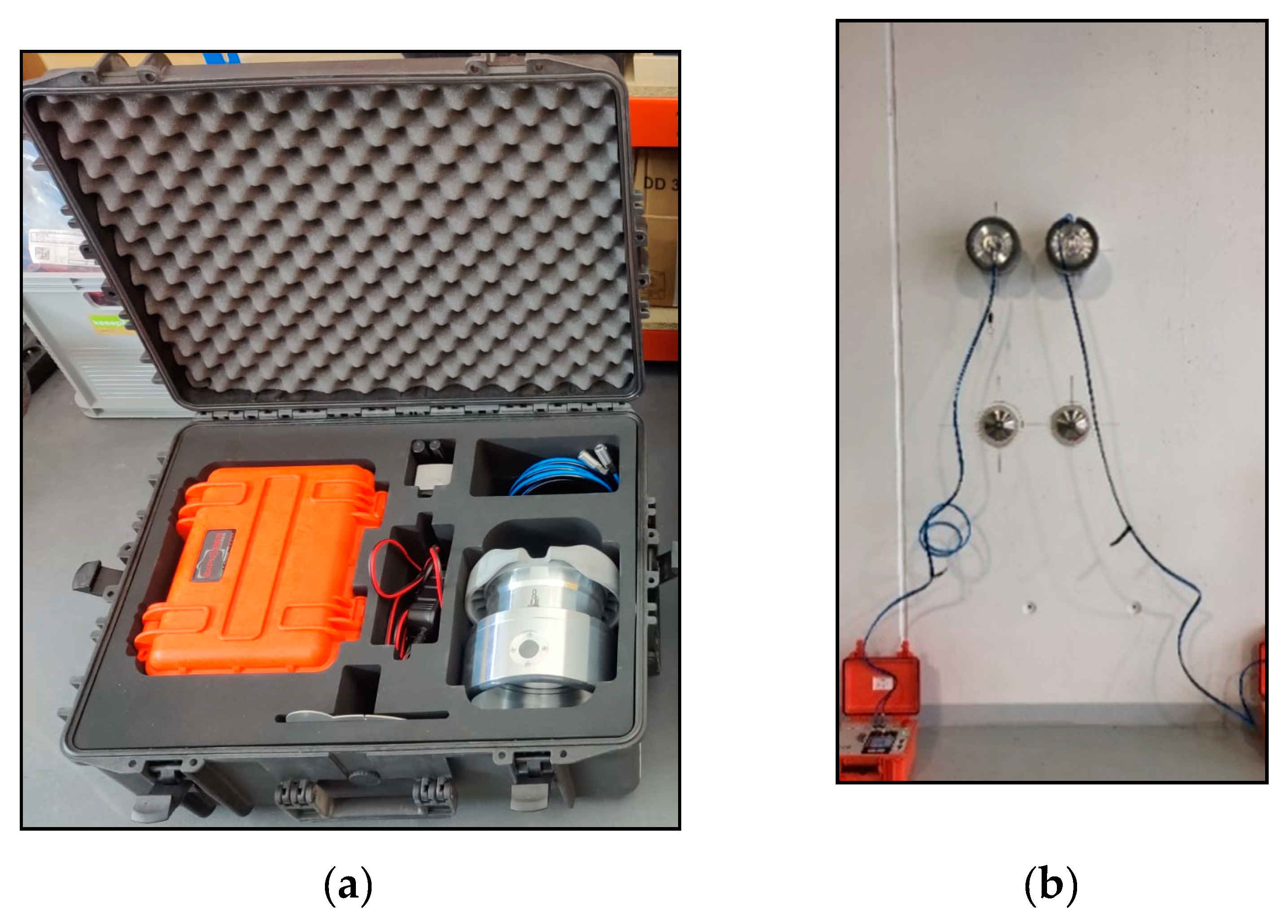
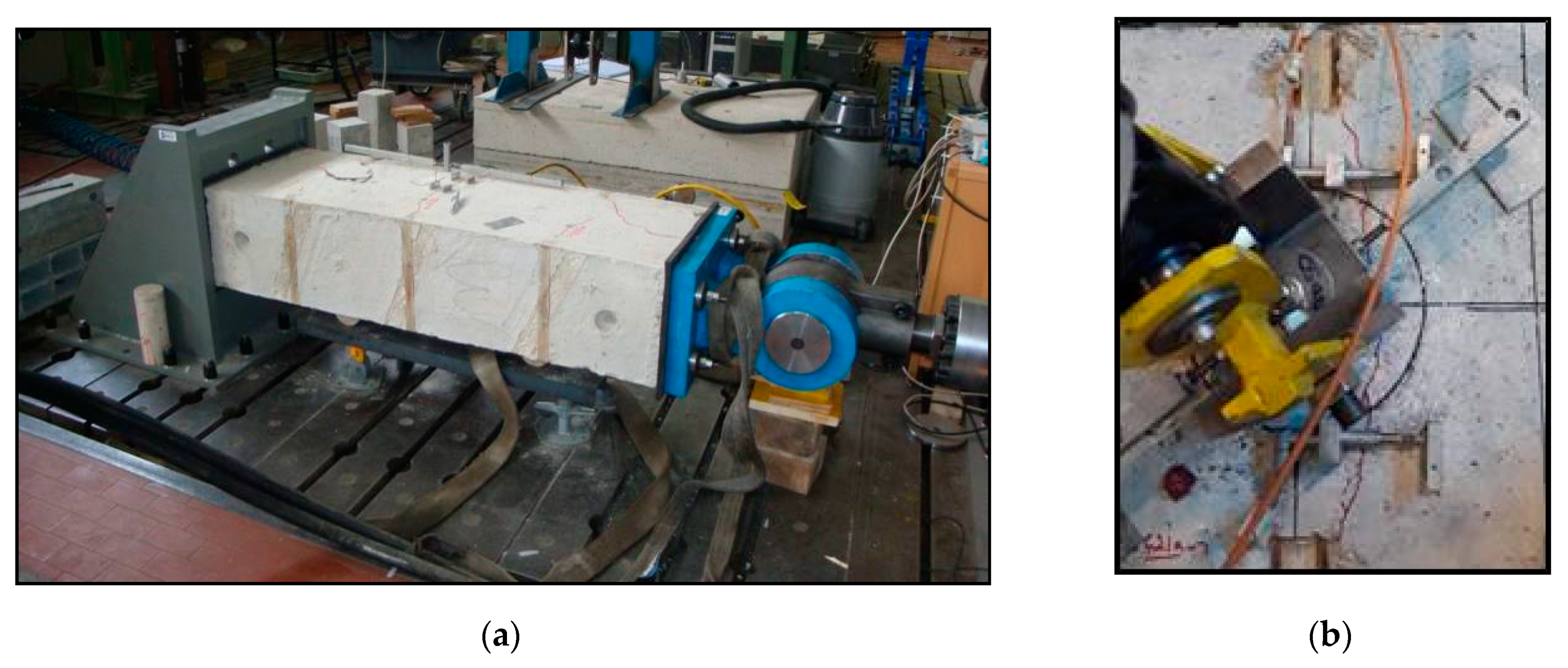
A picture of the test apparatus to create crack opening is reported in Figure 5a. Cracks were open by applying a tensile force (up to 800 kN) to the protruding steel rods. In case of the crack cycling test, the apparatus was able to apply a strength equal to 20% of the compressive strength of the concrete slab (up to 1000 kN).
LVDTs (range: 0–10 mm) were used to monitor the crack opening on both sides of the anchor during testing (Figure 5b).
In case of testing in uncracked concrete, the same apparati reported in Figure 5 were used, with the only difference consisting in locating the anchor plate between two neighboring crack planes.
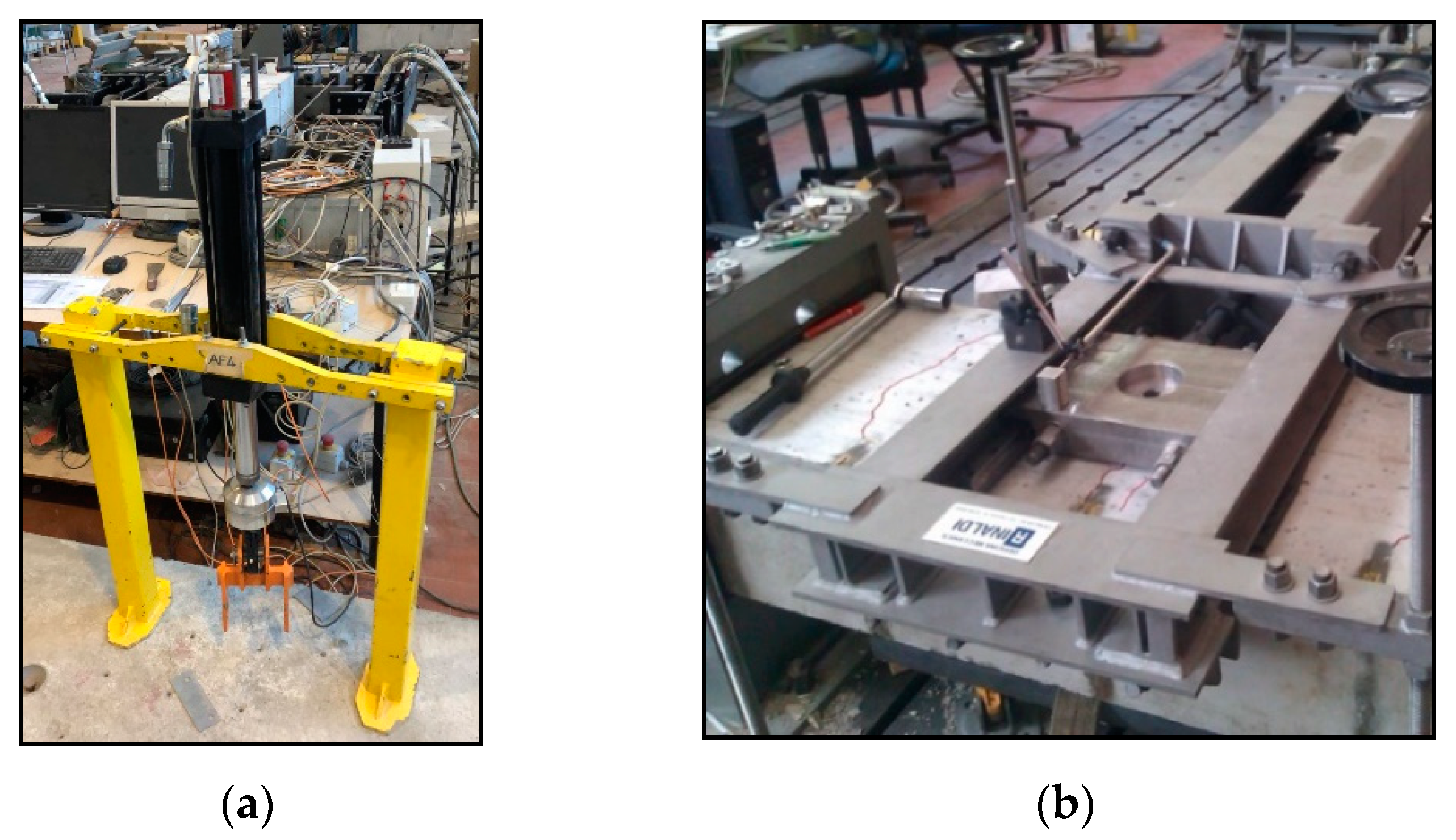
Regarding anchor loading, class I load cells with a 25 kN capacity for tension tests (Figure 6a) and a 200 kN capacity for shear tests (Figure 6b) were interposed between the jack and a steel device specifically designed to connect the steel bar protruding from the anchor plate with the same load cell. Two displacement transducers (with a 100 mm measuring range and a 0.001 mm accuracy) were positioned to measure the fastener slip. Data were automatically acquired at a 2 Hz frequency.
In shear, given the geometry of the test apparatus, the external force was applied through a stiff transfer plate with an eccentricity of 31 mm with respect to the concrete surface. Such a plate was able to slide laterally on the reaction frame (Figure 6b), which in turn was connected through tie-down rods to the strong floor. Generally, such a configuration is able to prevent the uplift of the fixture.
3. Test Results
The code for tensile tests is composed as follows:
where
X indicates test series and includes:
- A1 is the reference tension test in non-cracked concrete;
- A5 is the reference shear test in non-cracked concrete;
- C2.1a is the reference tension test in cracked concrete;
- C2.2 is the reference shear test in cracked concrete;
- C2.5 is the crack cycling under a tension load;
T indicates the type of anchor, i.e., a, b, c, A, B, and C;
N is a progressive number for each specific combination.
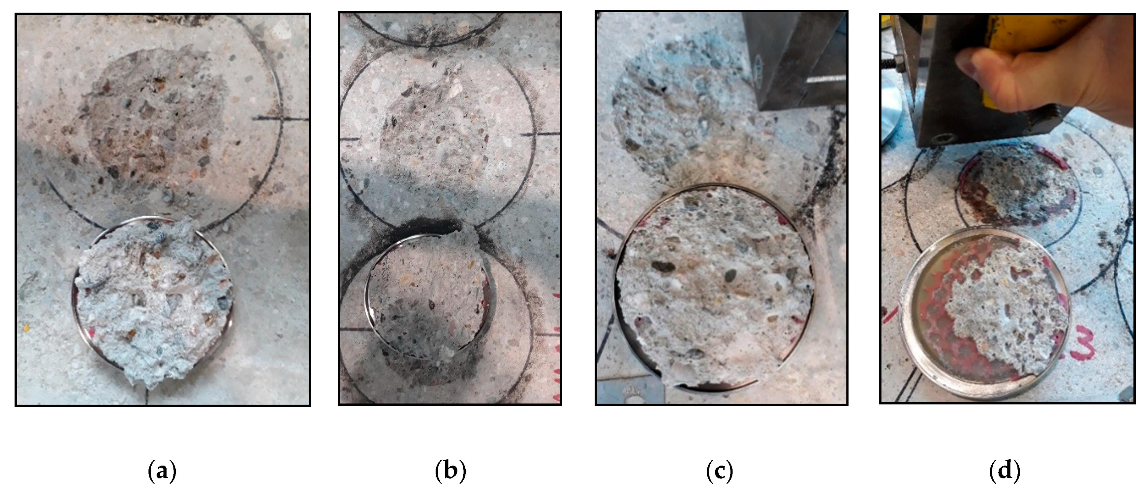
In both tensile and shear tests, a brittle delamination in the upper concrete layer was detected, which in some cases could be associated to the partial debonding of the plate (Figure 7).
The failure surfaces showed that a thin layer of concrete remained bonded to the anchor on the entire bonding surface, with the exception of a cellular interlayer where debonding from concrete was observed.
- the test code;
- the steel plate type;
- the crack width (if any);
- the peak tensile Nu or shear Vu load;
- the mean value of displacement at the peak tensile δ (Nu) or shear δ (Vu) load.
Table 4.
Test results of tensile loading.
| Test Code | Steel Type | Crack Width Δw (mm) | Peak Load Nu (kN) | Displacement δ (Nu) (mm) |
|---|---|---|---|---|
| A1_a_1 | 316L | 0.0 | 22.9 | 0.37 |
| A1_B_2 | HSS | 0.0 | 19.8 | 0.48 |
| A1_c_3 | 316L | 0.0 | 9.7 | 0.25 |
| C2.1a_B_4 | HSS | 0.8 | 14.6 | 0.33 |
| C2.1a_C_5 | HSS | 0.8 | 10.9 | 0.36 |
| C2.1a_a_6 | 316L | 0.8 | 15.3 | 0.41 |
| C2.1a_b_16 | 316L | 0.8 | 12.1 | 0.27 |
| C2.1a_C_17 | HSS | 0.8 | 5.4 | 0.19 |
| C2.1a_a_18 | 316L | 0.8 | 14.1 | 0.37 |
| C2.5_B_13 | HSS | 0.1 ÷ 0.8 | 2.3 | 0.20 |
| C2.5_A_14 | HSS | 0.1 ÷ 0.8 | 18.4 | 0.43 |
| C2.5_c_15 | 316L | 0.1 ÷ 0.8 | 10.5 | 0.26 |
Table 5.
Test results of shear loading.
| Test Code | Steel Type | Crack Width Δw (mm) | Peak Load Vu (kN) | Displacement δ (Vu) |
|---|---|---|---|---|
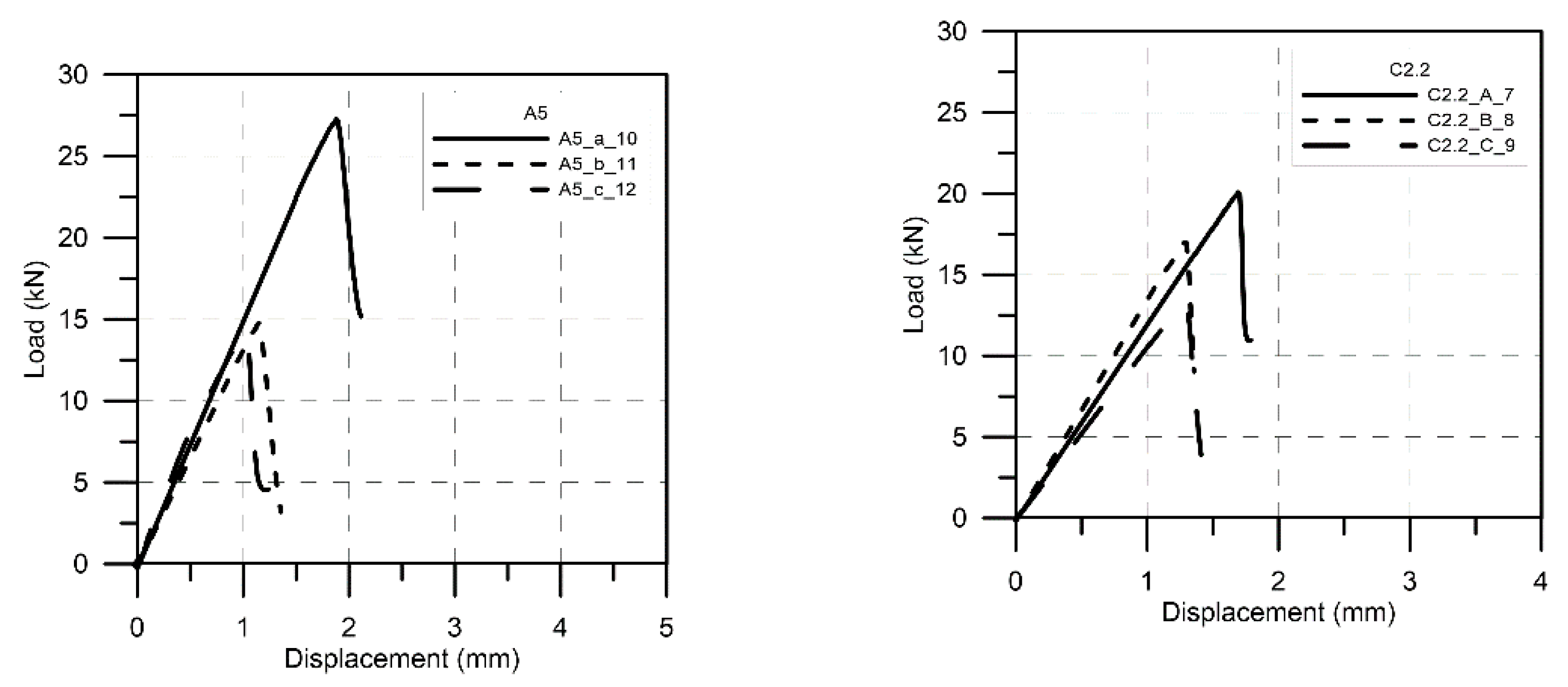
| A5_a_10 | 316L | 0.0 | 27.2 | 1.88 |
| A5_b_11 | 316L | 0.0 | 14.8 | 1.15 |
| A5_c_12 | 316L | 0.0 | 14.4 | 1.02 |
| C2.2_A_7 | HSS | 0.8 | 20.1 | 1.70 |
| C2.2_B_8 | HSS | 0.8 | 17.0 | 1.30 |
| C2.2_C_9 | HSS | 0.8 | 13.4 | 1.27 |
As for crack cycling tests (C2.5), type C was not able to conclude the crack cycling portion. Hence, no result was reported in such a case. In the other cases, the cumulated displacements at the end of crack cycling part were lower than 0.5 mm.
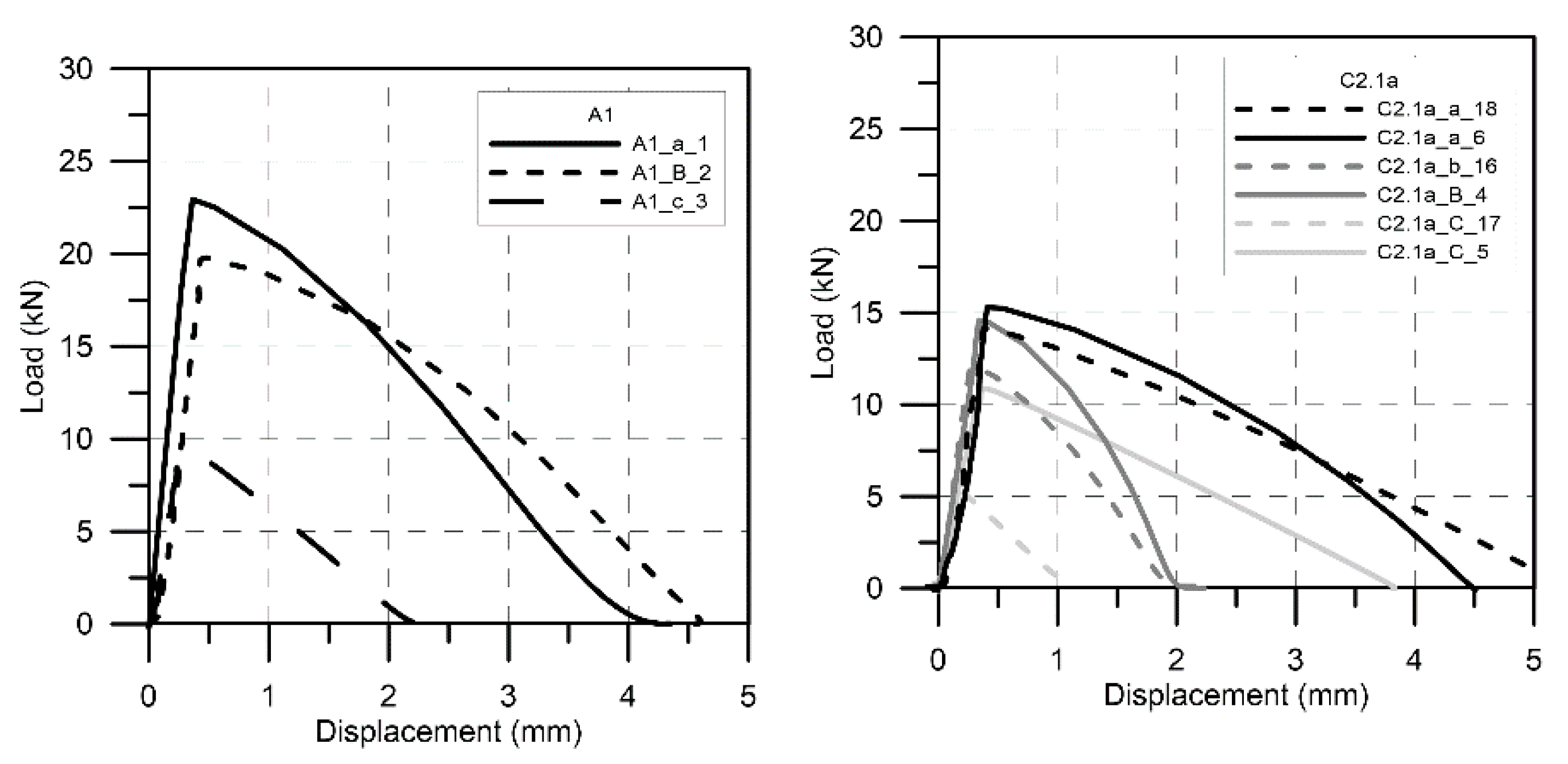
Figure 8 reports some significant load–displacement curves under tension loading.
In Figure 9, some significant load–displacement curves under shear loading are reported.
4. Discussion
Test results in terms of the mean capacity for each combination of crack width and anchor type are summarized in Table 6.
By comparing some significant load–displacement curves for the different test procedures (Figure 10), it is possible to observe that the stiffness of the load–displacement shear curves was lower with respect to tensile tests, suggesting that the connection stiffness was strictly related to the type of the applied load. Additionally, no significant difference was appreciated as for stainless or HSS. Given the attained load levels and on the basis of a visual observation of the specimens after failure, the risk of significant inelastic deformations due to the adoption of lower strength steel can be excluded.
Aiming to address the questions originally raised, a comparison of results in cracked and uncracked concrete showed how that the presence of a crack under the plate surface negatively affected the ultimate capacity of the fastener, as it could be expected. In fact, although not all test series in cracked and non-cracked concrete had the same number of tests, it is possible to observe that the presence of a crack pattern under the anchor plate affected the capacity of the fastener, with a reduction higher than 25% of the ultimate capacity compared to uncracked conditions. Additionally, crack cycling represented a severe condition for the anchor, noticing in type B fastener a huge reduction with respect to the monotonic loading cases, while type C fastener failed before the end of the cyclic portion of the tests, probably due to the weakness of the bonding agent in contact with a non-uniform surface as the cellular side of the IDL. On the other hand, without an IDL, crack cycling seemed to have a reduced impact compared to the reference cracking condition.
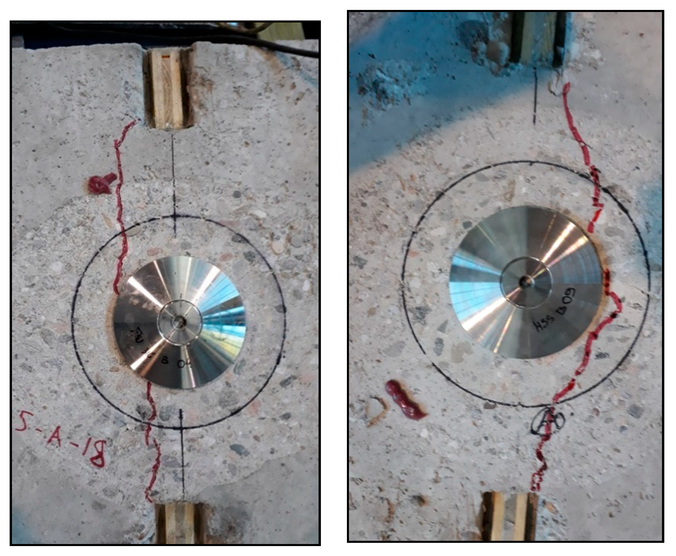
Finally, it is noted that fasteners seemed to have a bypassing effect for the surface crack (Figure 11), creating a preferential path for the crack propagation around the fasteners which deviated from the fasteners centroid. Surely, the impact of the randomness of such a process in determining the most appropriate conditions in terms of crack positions for this class of fasteners needs to be addressed in the future.
As for tension tests in uncracked concrete, it is shown that, for any material, the ultimate capacity in case of type A or a (no interlayer) was higher than for other types, especially in case of type C or c; this is probably due to the reduced contact area in type c associated with the cellular configuration of the interlayer. A similar behavior can be observed in uncracked shear tests, leading to the conclusion that the presence of an IDL seems to induce a lack of adhesion with a decay in tension capacity compared to for the case without an IDL.
5. Conclusions
A test campaign for a preliminary evaluation of the behavior of an anchor plate bonded on concrete was carried out.
Fasteners with the same geometry but in different materials (HSS or stainless steel), with or without an IDL and in both cracked and uncracked concrete were tested. It can be concluded as following:
- The proposed technology was found as generally effective in both tensile and shear load transfer to the concrete member;
- The use of HSS or stainless steel had negligible impact on the anchor behavior for the specific geometry of the plate;
- In the absence of an IDL, the performance of the fastener in both tension and shear tests were affected significantly by the presence of crack (compared to under the reference uncracked condition) and less by crack cycling (with respect to the reference cracked condition);
- The presence of an IDL seemed to induce a lack of adhesion at the concrete interface with a strong decay in tension capacity or even unsatisfactory performances, especially in crack cycling.
Finally, it is also noted that the presence of the fastener bonded “on concrete” seems to have a potential by-passing effect for the cracks, contrary to what happens for fasteners bonded “in concrete”, which act as crack inducers. Such results are encouraging in view of a further development of the system, with a deeper investigation of the role of an IDL, subjected to further optimizations.
Author Contributions
Conceptualization and methodology, A.N.C. and G.M.; investigation, data curation, writing—original draft preparation, A.N.C.; resources, writing—review and editing, supervision, project administration, funding acquisition, G.M. All authors have read and agreed to the published version of the manuscript.
Funding
This research was funded by Électricité de France (EDF) with the contribution of Cold Pad.
Data Availability Statement
Data available within the article.
Acknowledgments
In Technicians of the “Fastening” sector of Laboratory of testing Materials, Structures and Constructions of Politecnico di Milano are warmly acknowledged for their contribution to the arrangement of the test setup and the execution of the tests.
Conflicts of Interest
The authors declare no conflict of interest.
References
- Macdonald, M.D.; Calder, A.J.J. Bonded steel plating for strengthening concrete structures. Int. J. Adhes. Adhes. 1982, 2, 119–127. [Google Scholar] [CrossRef]
- Talysten, B. Strengthening of concrete prisms using the plate-bonding technique. Int. J. Fract. 1996, 82, 253–266. [Google Scholar] [CrossRef]
- Jones, R.; Swamy, R.N.; Ang, T.H. Under- and over-reinforced concrete beams with glued steel plates. Int. J. Cem. Compos. Lightweight Concr. 1982, 4, 19–32. [Google Scholar] [CrossRef]
- International Organization for Standardization. Mechanical Properties of Fasteners Made of Carbon Steel and Alloy Steel—Part 1: Bolts, Screws and Studs with Specified Property Classes—Coarse Thread and Fine Pitch Thread; ISO 898-1:2013; International Organization for Standardization: Geneve, Switzerland, 2013. [Google Scholar]
- Code, P. Eurocode 2: Design of Concrete Structures: Part 1-1: General Rules and Rules for Buildings; I.S. EN 1992-1-1:2005; British Standard Institution: London, UK, 2005. [Google Scholar]
- The British Standards Institution. Testing Hardened Concrete—Compressive Strength of Test Specimens; BS EN 12390-3:2019; The British Standards Institution: London, UK, 2019. [Google Scholar]
- European Organisation for Technical Assessment (EOTA). Bonded Fasteners for Use in Concrete; EAD 330499-00-0601; European Organisation for Technical Assessment: Brussels, Belgium, 2017. [Google Scholar]
- European Organisation for Technical Assessment (EOTA). EOTA TR 049: Post-Installed Fasteners in Concrete under Seismic Action; European Organisation for Technical Assessment: Brussels, Belgium, 2016. [Google Scholar]
Figure 3.
(a) Tooling for the installation of C-BLOCK fastener; (b) on-going installation cycle.

Figure 4.
Transverse and longitudinal sections for concrete specimens.

Figure 5.
Test apparatus for test in cracked concrete: (a) general view; and (b) details at the anchor location.
Figure 5.
Test apparatus for test in cracked concrete: (a) general view; and (b) details at the anchor location.

Figure 6.
(a) Apparatus for tension; (b) apparatus for shear.

Figure 7.
Failures of type a plate in uncracked shear (a), type b plate in the uncracked tension test (b), (c) type a plate in uncracked tension, and type c plate in uncracked tension (d).
Figure 7.
Failures of type a plate in uncracked shear (a), type b plate in the uncracked tension test (b), (c) type a plate in uncracked tension, and type c plate in uncracked tension (d).

Figure 8.
Tensile load vs. displacement curves.

Figure 9.
Shear load vs. displacement curves.

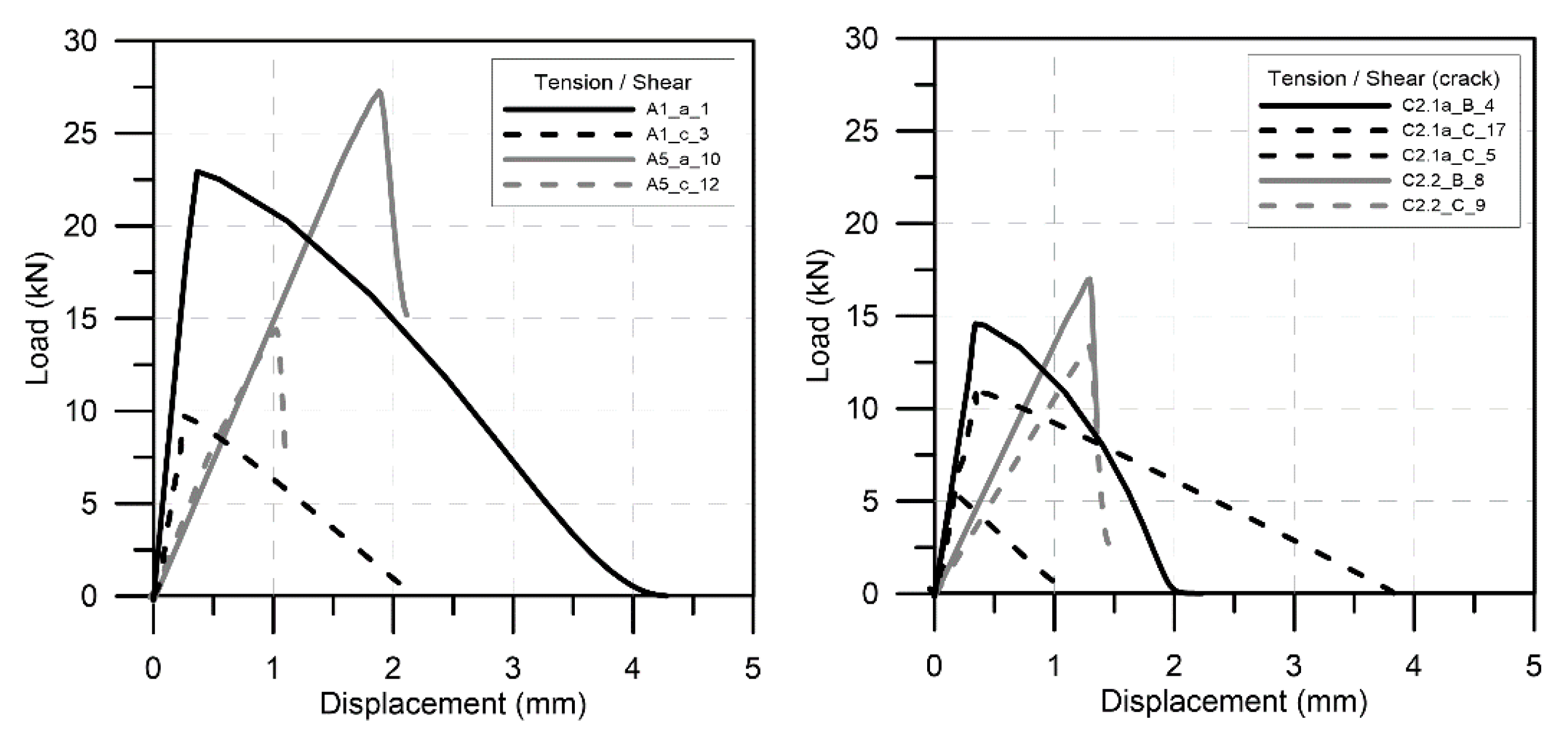
Figure 10.
Comparison between tension and shear tests.

Figure 11.
Examples of the preferential path of the crack around the fasteners.

Table 1.
Elastic limits of steel types (fasteners).
| Steel Part Material | Quantity of the Tested Fasteners | Elastic Limit (MPa) |
|---|---|---|
| 316L | 10 | 235 |
| HSS | 11 | 860 |
Table 2.
Mixed components.
| Mix Design | C20/25 |
|---|---|
| Cement CEM I 52,5 R (kg/m3) | 250 |
| Aggregate (kg/m3) Fine (0–4) Fine (0–8) Coarse (8–15) Coarse (15–25) | 300 (16%) 700 (37%) 270 (14%) 600 (32%) |
| Total aggregate (kg/m3) | 1870 |
| Superplasticizer (% on cement mass) | 0 |
| Water (l/m3) | 185 |
| Water/cement | 0.74 |
Table 6.
Test results in terms of the mean capacity for each combination of crack width and anchor type.
Table 6.
Test results in terms of the mean capacity for each combination of crack width and anchor type.
| Tension (kN) | ||||||
| crack (mm) | Type a | Type b | Type c | Type A | Type B | Type C |
| 0.0 | 22.9 | - | 9.7 | - | 19.8 | - |
| 0.8 | 14.7 | 12.1 | - | - | 14.6 | 8.1 |
| 0.1÷0.8 | - | - | 10.5 | 18.4 | 2.3 | failed |
| Shear (kN) | ||||||
| crack (mm) | Type a | Type b | Type c | Type A | Type B | Type C |
| 0.0 | 27.2 | 14.8 | 14.4 | - | - | - |
| 0.8 | - | - | - | 20.1 | 17.0 | 13.4 |
Publisher’s Note: MDPI stays neutral with regard to jurisdictional claims in published maps and institutional affiliations. |
© 2021 by the authors. Licensee MDPI, Basel, Switzerland. This article is an open access article distributed under the terms and conditions of the Creative Commons Attribution (CC BY) license (https://creativecommons.org/licenses/by/4.0/).
Share and Cite
MDPI and ACS Style
Consiglio, A.N.; Muciaccia, G. Anchor Plates Bonded on Reinforced Concrete: A Preliminary Experimental Investigation. CivilEng 2021, 2, 385-395. https://0-doi-org.brum.beds.ac.uk/10.3390/civileng2020021
AMA Style
Consiglio AN, Muciaccia G. Anchor Plates Bonded on Reinforced Concrete: A Preliminary Experimental Investigation. CivilEng. 2021; 2(2):385-395. https://0-doi-org.brum.beds.ac.uk/10.3390/civileng2020021
Chicago/Turabian StyleConsiglio, Andrea Nino, and Giovanni Muciaccia. 2021. "Anchor Plates Bonded on Reinforced Concrete: A Preliminary Experimental Investigation" CivilEng 2, no. 2: 385-395. https://0-doi-org.brum.beds.ac.uk/10.3390/civileng2020021