
Review of Testing and Qualification of Post-Installed Anchors under Seismic Actions for Structural Applications


Institute of Construction Materials, University of Stuttgart, 70569 Stuttgart, Germany
*
Author to whom correspondence should be addressed.
CivilEng 2021, 2(2), 406-420; https://0-doi-org.brum.beds.ac.uk/10.3390/civileng2020023
Submission received: 19 April 2021
/
Revised: 18 May 2021
/
Accepted: 21 May 2021
/
Published: 24 May 2021
(This article belongs to the Special Issue Connections in Concrete)
Abstract
:During earthquakes, buildings are subjected to loads well beyond their usual demands, resulting in high stresses in the structural components and additional inertial forces coming from the non-structural elements. When post-installed anchors are used to form the connection between non-structural or structural members and the primary reinforced concrete structure, these anchors are also subjected to high seismic demands. To determine whether a post-installed anchor is suitable for such applications, it is assessed for its performance under seismic demands. In this review paper, the current European approach for testing and qualification of post-installed anchors under seismic actions is reviewed and discussed in the context of structural applications where anchors are used to form the connection between structural members that participate in the load-transfer mechanism against seismic loads. The first part of this paper provides a description of the testing procedures and the criteria against which the anchor performance is assessed. The procedures and assessment criteria are discussed regarding the suitability in the case of the above-described structural applications. In the second part, the qualification of anchors under seismic actions is discussed in the light of an upcoming performance-based design approach for anchors. In such an approach, information on the displacement and hysteretic behavior of an anchor in a broader range of the load–displacement curve is of vital importance. Therefore, additional testing approaches might be required in order to supplement the information on anchor performance provided in the current testing procedures. One such testing approach for pulsating tension load is reported.
1. Introduction
Knowing how a structure or an individual structural element behaves during an earthquake is critical when determining the performance of new buildings or selecting an adequate strengthening solution for an existing building. To this end, seismic tests are performed at the structural level or at the sub-assembly level to assess the behavior under seismic actions. Various methods are used in practice to test structures and structural elements, such as shake table tests where structures are subject to simulated earthquake motions [1], or simpler methods such as quasi-static tests [2,3]. Here, pre-defined forces or deformations are applied to the structures or sub-assemblies. Furthermore, new methods on how to conduct seismic tests are investigated, such as the use of a vibrodyne, which is an electro-mechanical excitation machine generating vibrations with known frequency and amplitude [4].
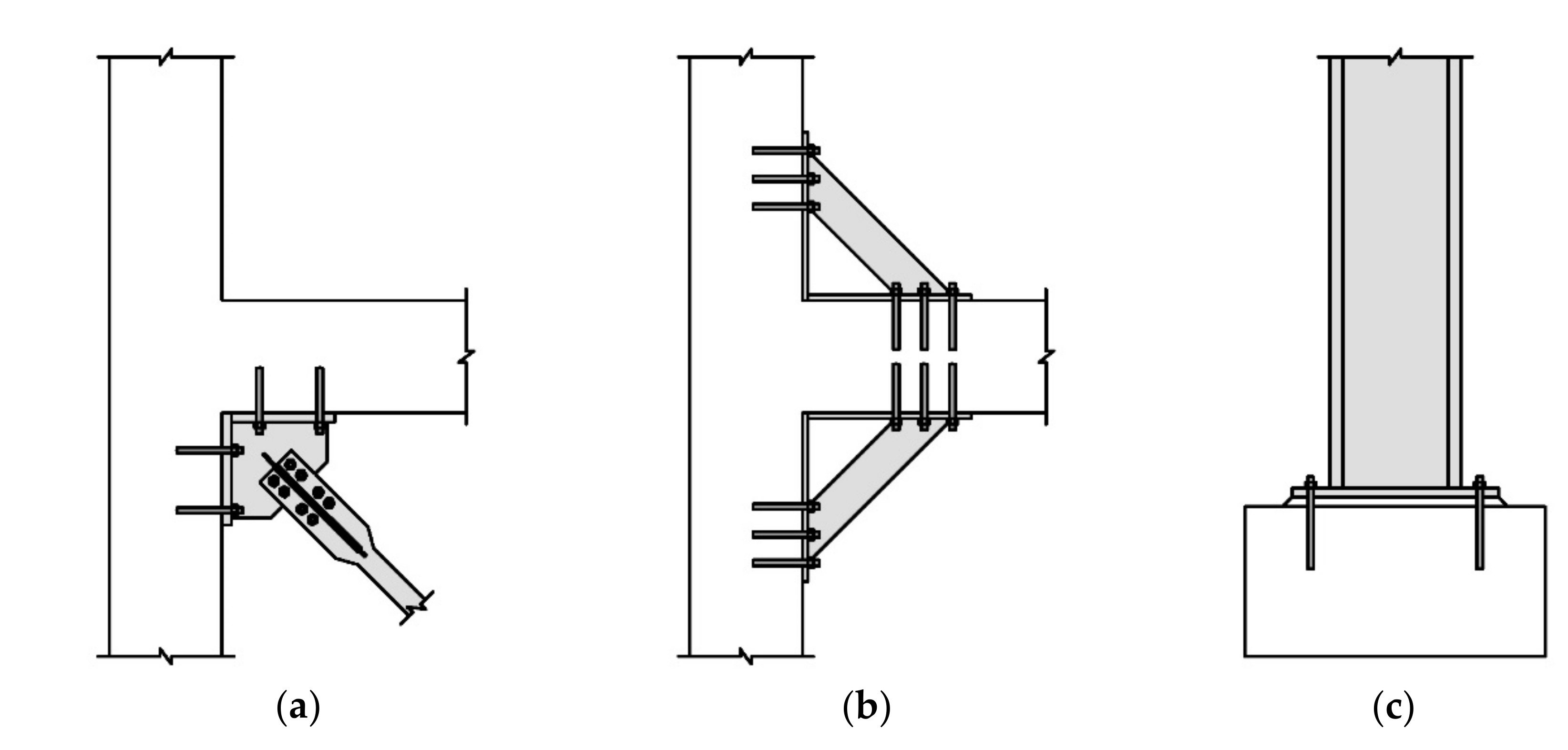
When connecting structural elements, the connection itself is often decisive. Nowadays, post-installed anchors are used in many areas to connect additional elements to an existing structure. Often, the new elements are aimed at strengthening the existing structure, as is the case with strengthening of masonry structures using steel frames [5] or frames made of Pultruded Fiber-Reinforced Polymer profiles [6]. Thereby, the effectiveness of the strengthening solution can be increased by adequate connection of the new elements to the existing structure as shown in [5]. Moreover, post-installed anchors are frequently used to attach additional structural elements to reinforced concrete (RC) structures. Typical examples of structural connections are the attachment of steel beams or columns, steel bracings, or steel haunches as illustrated in Figure 1. In the case of earthquakes, these connections have to withstand high demands such as cyclic tension and shear loading. Furthermore, as shown in [7], anchors tend to attract cracks since they act as a notch, leading to high stress concentrations. Due to the cyclic deformation of the primary structure, these cracks open and close while the anchors are simultaneously subjected to cyclic loading.
When connecting structural strengthening elements to RC structures, the performance of the connections and hence the performance of the anchors are crucial to the safety of the structure and the effectiveness of the attached element. The extent to which the anchor behavior influences the overall performance becomes evident in experimental studies where post-installed anchors were used to attach strengthening solutions against earthquake hazards, such as steel bracings [8] or steel haunches [9]. In these experiments, the displacement behavior of the anchor was identified as decisive for the success of the strengthening solution. As shown in [10], a geometric imperfection in the gusset plate used to connect the steel bracing to the RC frame can lead to local buckling of the end portion of the steel bracing and thus to a reduction in the effectiveness of the strengthening solution. Such geometric imperfections can be caused by unrecoverable anchor displacements as shown in [8]. In [9], it was found that, depending on the type of anchor, the overall behavior of the strengthened members varied significantly. This is due to the fact that the performance of an anchor and its load-displacement behavior differ substantially depending on what type of post-installed anchor is used. In view of the high demands and the importance of favorable anchor behavior under seismic actions, it is clear that determining the suitability of an anchor for such applications is the basis for a safe and practical design.
In Europe, post-installed anchors are assessed for their performance under seismic actions according to EOTA TR 049 [11]. Within the guideline, a distinction is made between two performance categories, namely C1 and C2, to which specific tests and testing procedures apply. The two categories are defined in the European standard EN 1992-4 [12] and are related to the level of seismicity in terms of ground acceleration and the building performance class, which are described in EN 1998-1 [13]. In addition, the German national annex DIN EN 1992-4/NA [14] further relates the performance categories to the expected damage in the base material characterized by means of the calculated crack width. Hence, the damage level of the building is also taken into consideration when choosing the appropriate performance level. In general, category C1 is used primarily for anchors used to connect non-structural elements to the structure [15], whereas category C2 is generally used for anchorages used to connect both structural and non-structural elements to the existing structure. This includes, among other things, structural connections for seismic strengthening. Consequently, C2 is deemed more stringent, featuring more demanding test procedures and more rigorous requirements for qualification.
The objective of this paper is to first give an overview of the current testing procedures and qualification requirements for post-installed anchors under seismic actions relevant to structural applications that are currently used in Europe. The current approach is discussed in the light of structural strengthening applications against earthquakes and the concept of performance-based design, which is becoming increasingly popular in the earthquake engineering community both in the design of new structures and the retrofit of already-existing structures.
2. Testing Procedures
2.1. Overview
Due to the focus of the paper on structural applications, the review is done only for the testing procedure according to the C2 category. Category C2 includes static reference tests for tension and shear load in cracked concrete (C2.1 and C2.2, respectively), tests under pulsating tension load (C2.3), tests under alternating shear load (C2.4), and crack cycling tests with constant tension load (C2.5). The crack cycling tests are generally deemed the most demanding tests and are often pivotal to the qualification of the anchors as shown in [16]. A summary of the required tests for category C2 is given in Table 1. The loads Nmax and Vmax, presented in Table 1, are the maximum loads during the cycling phase in the respective test series. The maximum load values are determined from the mean ultimate loads Nu,m,C2.1 and Vu,m,C2.2 obtained from the static reference tests in tension and shear, respectively. In the case of the crack cycling tests, two load levels are defined, Nw1 and Nw2. As can be seen, the maximum considered crack width in category C2 is Δw = 0.8 mm. Thereby, Δw refers to the crack opening in addition to the hairline crack after the anchor has been installed but before the test has started. The determination of an upper limit for the crack width is based on the specifications in EOTA TR 049 [11], limiting the use of post-installed anchors to areas outside of plastic hinge zones. Considering this specification, the maximum crack width in a RC bending member can be related to the onset of yielding of the reinforcement. Analytical studies conducted by [17,18] determined the crack width at steel yield strain for various RC cross sections using empirical equations given in standards and the literature. In these studies, various parameters such as steel ratio, number of longitudinal bars and bar diameter, neutral axis depth, and concrete cover were considered. It was found that 0.8 mm reasonably well represents the crack width for which post-installed anchors, designed according to EN 1992-1 [19], need to be tested for in the case of seismic demands.
2.2. Tests for Category C2
Cyclic tests for category C2 were developed with the consideration that both the anchor performance at the suitability level and at the serviceability level can be assessed in one test series [20]. Thereby, suitability refers to the ability of an anchor to function well under rather extreme conditions, such as the maximum considered crack width Δw = 0.8 mm and cycling loading up to the characteristic strength of the anchor. ‘Serviceability’ refers to the displacement behavior of an anchor under moderate conditions such as medium crack widths and loading up to the design strength of the anchor. In the following subsections, the tests according to category C2 are discussed.
2.2.1. Static Reference Tests—Test Series C2.1 and C2.2
In category C2, static reference tests in tension and shear are conducted prior to the cyclic test series. The reference tests are conducted in cracked concrete with a crack width of Δw = 0.8 mm. The tests are performed in order to obtain the parameters that are required to define the loading histories for the test series C2.3, C2.4, and C2.5, that are the mean ultimate loads Nu,m,C2.1 and Vu,m,C2.2.
2.2.2. Test Series C2.3—Pulsating Tension Load
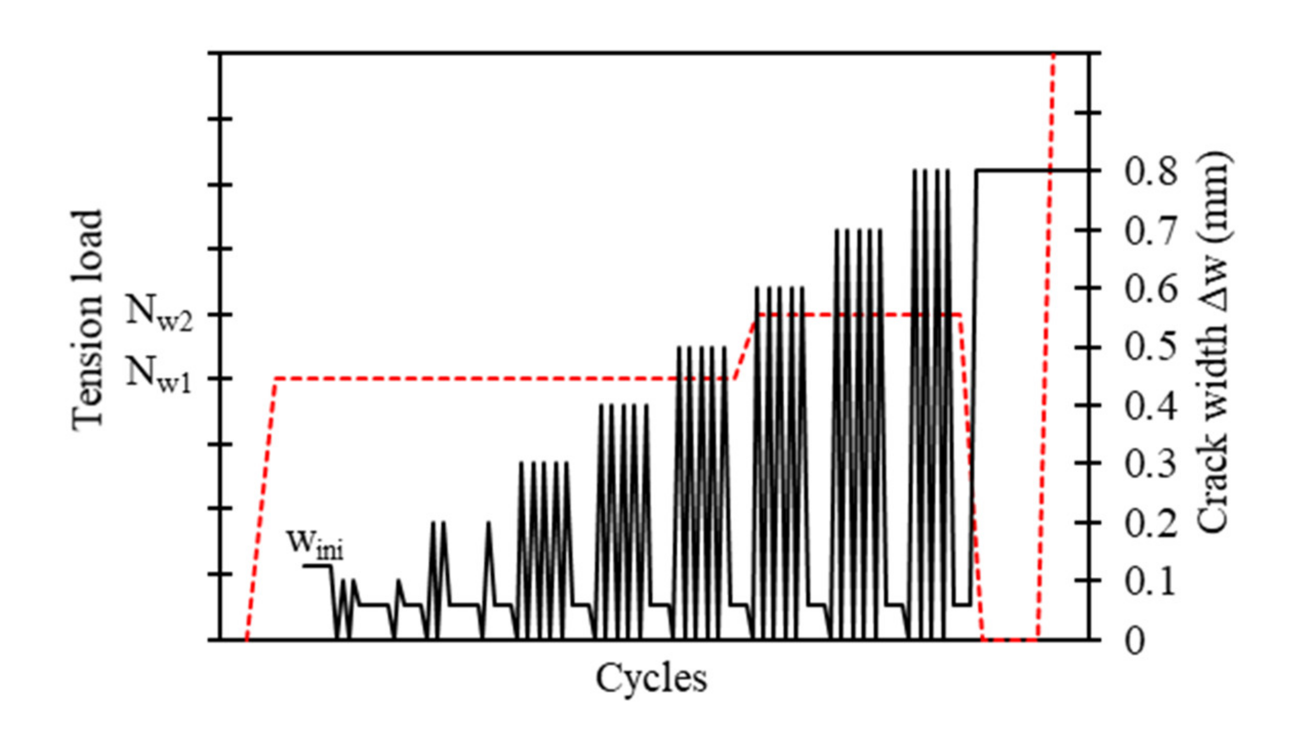
The testing procedure for pulsating tension load can be divided into two parts. The first part of the protocol is the cycling phase where the anchors are axially loaded in tension following the loading history shown in Figure 2. The cycling frequency of the sinusoidal tension loads should not exceed 0.5 Hz. As can be seen, the load is stepwise increased in steps of 0.1 Nmax, starting at 0.2 Nmax and increasing up to the maximum load Nmax, which is defined as 75% of the mean ultimate load obtained from the reference tension tests C2.1. After completion of the loading history, the anchors are unloaded and then statically loaded in tension until failure. This residual pullout test is the second part of the protocol intended to determine the residual tension capacity of the anchors.
In the cyclic loading phase, the load is stepwise increased, which has, in comparison with loading histories with stepwise decreasing load as featured in category C1 according to EOTA TR 049 [11] or testing procedures according to the American qualification guidelines ACI 355.2 [21] and ACI 355.4 [22], the major advantage that the information on anchor stiffness can be obtained in the complete cyclic loading range [23]. As mentioned above, the procedure is intended to provide information on the anchor performance at the suitability level and at the serviceability level. In the cyclic loading history for C2.3, this is considered by two aspects. The first aspect reflects the applied loads. The maximum applied load during load cycling, Nmax, is considered as the maximum characteristic load for the suitability level. The characteristic value is calculated as the 5% fractile from the mean ultimate load obtained from the reference tension tests C2.1, assuming a coefficient of variation of 15%. At the serviceability level, the characteristic values are reduced to the design level using partial safety factors for the load and material, leading to roughly 50% of the characteristic value, 0.5 Nmax [20]. The second aspect reflects the condition of the base material. The test procedure starts at a crack width of Δw = 0.5 mm, which represents the crack width at the serviceability level. The value corresponds to the maximum considered crack width in category C1 according to EOTA TR 049 [11] and the American qualification guidelines ACI 355.2 [21] and ACI 355.4 [22]. After completion of the load cycles at 0.5 Nmax, the test is paused, and the crack width is increased to Δw = 0.8 mm, which reflects the suitability level. It should be noted that the complete procedure might also be performed with a Δw = 0.8 mm crack width.
In total, the cyclic loading history comprises 75 cycles, of which 25 are performed in the first load step, 15 in the second load step, and five in each subsequent load step. The number of cycles at each load level was determined on basis of a numerical study on RC buildings with a wide range of dynamic characteristics. These buildings were subjected to various scaled ground motions in order to determine their seismic response. Single-degree-of-freedom (SDOF) systems with various frequencies, representing non-structural mechanical and electrical elements, were then subjected to the floor-level time histories. The obtained time history responses from the buildings and SDOF systems, together with the curvature histories at beam ends, were used to develop the cycle counts per load level for the cyclic loading protocols for tension and shear load and the crack cycling protocol [20].
2.2.3. Test Series C2.4—Alternating Shear Load
Similar to the protocol for pulsating tension load, the protocol for alternating shear load can be divided into two parts: a cycling phase and a residual capacity test. In the cycling phase, the anchors are subjected to sinusoidal shear load as shown in Figure 3 with a maximum cycling frequency of 0.5 Hz. In contrast to the C2.3 protocol, the testing procedure for alternating shear load starts at a crack width of Δw = 0.8 mm and the complete test is performed at this crack width level. This approach has the beneficial effect of simplifying the testing procedure and is based on results from shear tests on anchors that have shown that the crack width had only a minor influence on the anchor behavior [15,24]. The maximum load during load cycling is Vmax as given in Table 1. Vmax is considered as the maximum characteristic load for the suitability level and is derived as the 5% fractile from the mean ultimate load obtained from the reference shear tests C2.2, assuming a coefficient of variation of 10%. As with the C2.3 tests, the load is stepwise increasing, starting at a load level of 0.2 Vmax and increasing the load in each step by 0.1 Vmax until the maximum load is reached. Thereby, similar to the loading history in C2.3, 25 cycles are performed in the first load step, 15 cycles in the second load step, and five cycles in each subsequent load step. After the cyclic loading phase has been completed according to the loading history, the anchor is unloaded and then statically loaded in shear until failure to determine the residual capacity. The load on the anchor is applied parallel to the crack.
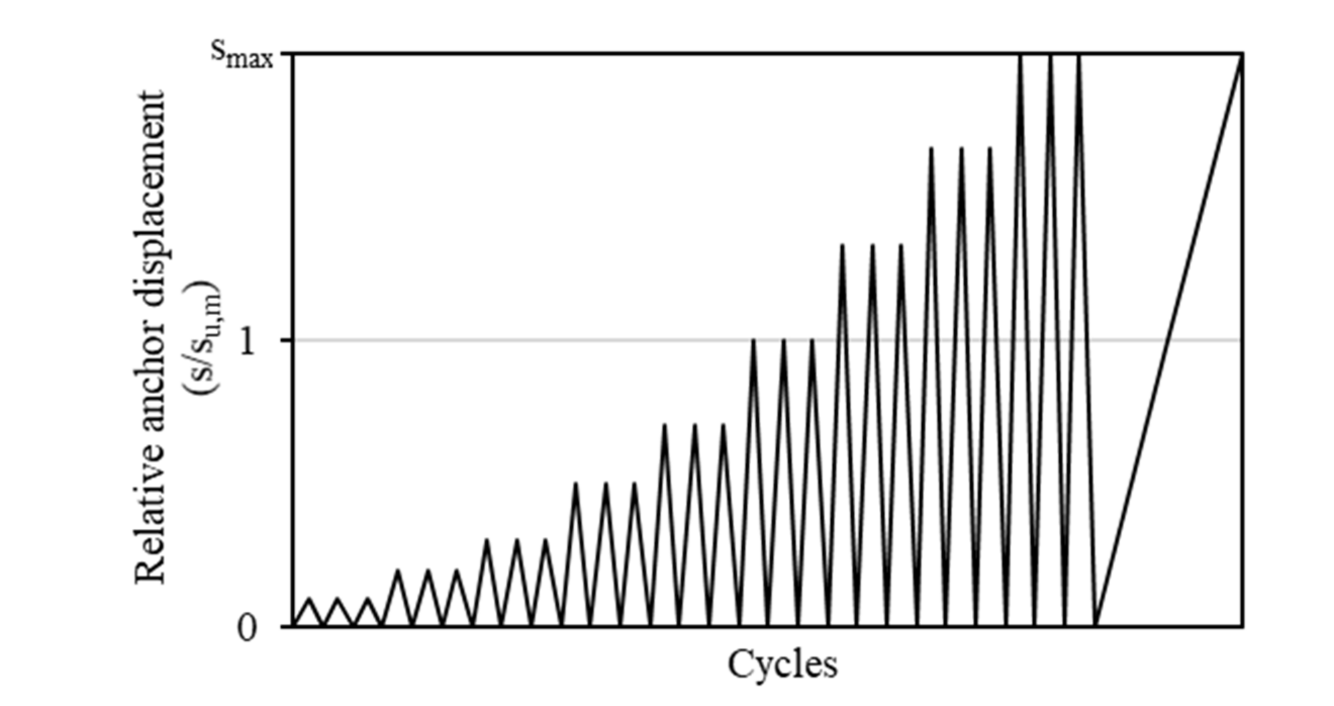
2.2.4. Test Series C2.5—Constant Tension Load and Varying Crack Width
Test series C2.5 is an additional test for seismic anchor qualification in comparison to other methods for seismic testing of anchors such as the category C1 tests and it is frequently found to be decisive for assessing the anchor behavior under tension as shown in [16]. The cyclic loading protocol features stepwise increasing crack widths starting from a crack width of Δw = 0.1 mm. In each step, the crack is opened further by 0.1 mm to the crack width of Δw = 0.8 mm. Consistent with test series C2.3, the maximum considered crack width at the serviceability level is Δw = 0.5 mm and at the suitability level the maximum considered crack width is Δw = 0.8 mm. The applied constant tension load at the suitability level, Nw2, is determined by dividing the characteristic load, Nmax, by the material safety factor. At the serviceability level, the constant tension load, Nw1, is taken as 80% of Nw2.
In real applications, the load would be cycling along with the opening and closing of the crack. Depending on the application itself, the load and crack cycling can either be out-of-phase or in-phase or have a particular phase difference or even be random in nature. Probabilistic studies [25] showed that, for most cases, for non-structural applications, when the crack width would reach its maximum value, the tension load would be lower than 80% of its peak value. Experimental studies conducted by [26] indicate that crack cycling at constant tension load yields the most conservative results in comparison with out-of-phase or in-phase anchor tests. Nevertheless, tests in which the load and cracks are cycled simultaneously are elaborate and therefore do not fulfill the requirement of qualification tests to be reasonably easy to carry out. Thus, this potentially beneficial effect of phasing is reflected in the reduction of Nw2 to 80% for the serviceability level in EOTA TR 049 [11].
On the other hand, another experimental study [27] showed that the displacement behavior of anchors under different load and crack cycling protocols depends on various parameters. They argued that the assumption of a constant tension load applied on the anchor during crack cycling tests may or may not be conservative depending on the anchor type, the crack width, and/or the embedment depth. However, the residual load capacity after the crack cycling is not influenced by any load-crack-cycling protocol.
The test procedure first requires the hairline crack to be opened by applying tension on the reinforcing bars of the test specimen. Thereafter, a centric compression force, Cini, is applied on the concrete specimen to ensure similar starting conditions when using concrete specimens with one crack plane and concrete specimens with multiple crack planes. The compression force Cini is calculated as:
where Ag is the cross sectional area of the concrete specimen and fc,C2.5 is the mean concrete cube compressive strength at the time of testing. However, experimental results by [28] indicate that for a test specimen with multiple crack planes (as is commonly used in the tests), applying Cini is unlikely to result in equivalent test conditions for each test. It was shown that while controlling the crack width during cycling, the limit of Δw = 0.8 mm was indeed complied with, but the absolute range of the crack width was considerably higher. Furthermore, Cini seems to have no significant effect on the anchor behavior as experiments on specimens with only one crack plane indicate [28].
Cini = 0.01 ∙ fc,C2.5 ∙ Ag,
The test procedure continues with the installation of the anchor in the hairline crack. In the case of bonded anchors or bonded expansion anchors, the compression force Cini should be removed during installation and curing and then afterwards reapplied. The test starts by applying the tension load Nw1 (see Table 1) on the anchor. With the constant tension load, the crack cycling is started following the procedure shown in Figure 4 with the first crack movement being in the direction of the crack’s closure. For closing the crack, a compression force, Ctest, is centrically applied on the concrete specimen, which is calculated with the following equation:
Ctest = 0.1 ∙ fc,C2.5 ∙ Ag.
It was shown in [29] that the application of Ctest for closing the crack has a considerable negative effect on anchor displacements. Due to crushing of the base material around the load transfer point, the anchor displacement increases. In [28], it was shown that the compression force Ctest is generally higher than the actual force, which is required to reach zero crack width, resulting in additional compression of the concrete specimen. However, experimental results indicate that compression loads beyond those required to completely close the crack have no additional negative effect on the anchor displacement behavior [29]. In general, closing the crack by applying compression forces on the concrete specimen reflects the structural behavior of a building during an earthquake, where the base material of anchors such as RC beams and columns are alternately loaded in tension and compression. Therefore, closing the crack by applying Ctest is deemed to be a reasonable approach.
After completion of the crack cycles at a crack width of Δw = 0.5 mm, the test is paused, and the constant tension load is increased to Nw2 (see Table 1). After completion of the crack cycling procedure, the anchor is loaded in tension until failure in order to obtain the residual capacity. The crack cycling frequency should not exceed 0.5 Hz. In total, 59 crack cycles are performed with 20 cycles at a 0.1 mm crack width, 10 cycles at a 0.2 mm crack width, five cycles each at a 0.3–0.7 mm crack width, and four cycles in the last step at a 0.8 mm crack width.
2.3. Discussion
It has been shown that the procedures for the cyclic tests in category C2 basically consist of two phases. A first phase in which a cyclic demand is applied, and the anchor is tested for its cyclic behavior, and a subsequent second phase where the anchor is loaded until failure in order to determine the residual capacity. The load-cycling tests are performed in force-control with stepwise increasing load levels during the cycling phase whereby the maximum applied load during cycling is the maximum considered characteristic load determined from the static reference tests in cracked concrete.
In cases where anchors are used to form the connection between a non-structural element and the primary structure, the force-controlled procedures are deemed suitable for simulating the real demands on anchors. Thus, the information obtained from these force-controlled procedures can be considered sufficient to ensure reliable anchor behavior during an earthquake. One reason for this is that the forces acting on the anchors during an earthquake can be reasonably well estimated in terms of inertial forces. These forces result from the oscillation of the connected elements due to the cyclic deformations of the overall structure. As the seismic demands acting on such a connection are sufficiently well-known during the design process, it can be assumed that, in this case, cycling up to the characteristic strength covers the relevant part of the hysteretic behavior of an anchor. Secondly, the number of load and crack cycles was determined in such a way that they correspond to the expected frequency of load reversals in non-structural applications and therefore realistically represent the number of cycles for which the load must be resisted by the anchorage. Besides the specified cyclic demand, the residual capacity test in the second phase of the procedures is of particular importance. The requirement that the strength of an anchor after a seismic demand is still sufficiently high ensures that the fastened elements are prevented from falling down and allows for the safe reoccupation of the building after an earthquake, if need be.
When it comes to connecting structural elements that are part of the load-transfer mechanism against seismic actions, it becomes considerably more difficult to estimate the demands that will actually be imposed on the anchors. Two aspects in particular should be considered. The first aspect considers current design approaches against seismic actions. When a new structure is designed against seismic actions or an existing structure is strengthened in order to improve its behavior against seismic loads, current standards such as EN 1998-1 [13] are generally taking into account the beneficial effect of ductile behavior and energy dissipation of certain structural members by reducing the seismic demand on the structure. Thereby, the ductility is estimated based on the used materials and the structural system. However, if the structure is not able to achieve the assumed ductility, and hence the capacity to dissipate energy is not as high as assumed, it is apparent that the forces that have to be taken up by the structural system are higher than the forces for which the structure was actually designed. In turn, the forces acting on the anchors that form the connection between structural elements will become significantly higher. The second aspect concerns the case when the structure is undergoing deformations in the non-linear range. In this case, certain members of the structure will form plastic hinges resulting in increasing displacement demands on the remaining structural members and connections. In addition to the increased displacement demands, it should be noted that although in current standards such as EN 1998-1 [13] the structure is expected to be in the non-linear range, the resulting force redistribution due to the formation of plastic hinges is generally ignored. This again might result in significantly higher forces on the anchors than expected during the design process. In this context, the non-linear behavior of anchors, including the hysteretic behavior in the non-linear range, becomes more relevant for designing this kind of connection. Force-controlled testing procedures might be insufficient to provide the required information for such a design and a displacement/performance-based approach might offer a better approach for qualification of anchors used for structural applications under seismic actions.
3. Assessment of the Experimental Results
The assessment criteria specified in EOTA TR 049 [11] define the requirements post-installed anchors must meet to be approved for seismic applications in category C2. Thereby, the anchor performance is assessed in terms of its ability to provide sufficient capacity after a specified seismic load and the deformations of the anchor at the serviceability level. Based on the assessment criteria, reduction factors, α and β, are determined, which are used to calculate the characteristic seismic resistance of the anchor. Thus, if certain requirements cannot be met by an anchor, its characteristic resistance is reduced accordingly. In addition, certain requirements determine whether an anchor is at all suitable for use in seismic applications for category C2. Correspondingly, not meeting these requirements results in an anchor not being qualified for the category C2. A detailed description of the assessment procedure is provided in EOTA TR 049 [11].
3.1. The α Reduction Factor
The α reduction factors in the static reference test series C2.1 and C2.2, αC2.1 and αC2.2, are determined solely based on the mean ultimate capacity. Therefore, the guideline stipulates a specific limit value for the ultimate capacity, which is based on the mean tension capacity from the tests for maximum crack width and large hole diameter in cracked concrete C20/25 according to EAD 330232 [30], tests for sensitivity to increased crack width in concrete C20/25 according to EAD 330499 [31], and tests for characteristic resistance to steel failure under shear load according to EAD 330232 [30]. In the case of the cyclic test series C2.3, C2.4, and C2.5, in each test series three criteria are assessed for each of which a particular α reduction factor is determined. The final α reduction factors for the respective test series, αC2.3, αC2.4, and αC2.5, are ultimately determined from these three. The first criterion stipulates the completion of the cyclic loading history. If an anchor fails to complete the cyclic loading history, the test series has to be repeated with a reduced load value. Provided that the anchor completes the seismic loading history with the reduced load, the reduction factor α1 is calculated as the ratio between the reduced load and the initially considered maximum load for the cycling phase. The second requirement introduces a displacement limit after completion of the last cycle of the serviceability level. At this point, the mean value of the anchor displacement is limited to a value of 7 mm. If the anchor fails the requirement, the tests are conducted with a reduced load value until the requirement is met. The corresponding reduction factor, α2, is calculated as the ratio between the reduced load and the initially considered maximum load for the cycling phase. The third criterion considers the mean ultimate load obtained in the residual capacity tests. In the case of the cyclic tension test series (C2.3 and C2.5), the mean ultimate load shall be at least 90% of the mean ultimate load obtained from the static reference test series C2.1 and in the case of the cyclic shear test series C2.4, the mean ultimate load shall be at least 95% of the mean ultimate shear load obtained in the reference test series C2.2. If the mean ultimate load in the residual capacity test is below the stipulated target load value, the corresponding reduction factor, α3, for the respective test series is calculated as the ratio between the actually obtained mean ultimate load and the target load value.
Based on the reduction factors for the test series, eventually one final α reduction factor is calculated for tension and shear, respectively.
3.2. The β Reduction Factor
In category C2, a second reduction factor, β, is introduced to determine the characteristic seismic resistance. This β reduction factor considers the scatter of ultimate loads in the residual capacity tests in the cyclic test series and the scatter of ultimate loads in the static reference test series. The scatter is defined in terms of the coefficient of variation (CV). In the case of the tension tests, the CV is limited to 20% and in the case of shear tests it is limited to 15%. If in a test series the CV is larger than 30%, the anchor is generally considered unsuitable for use in category C2. Based on the reduction factors for the test series, eventually one final β reduction factor is calculated for tension and shear, respectively.
3.3. General Criteria for Suitability of an Anchor and Provided Information on Displacements
Besides the assessment criteria discussed so far, category C2 includes certain assessment criteria that will, in case the anchor is unable to meet the requirement, result in the anchor not being approved for this seismic category. These criteria are intended to ensure that an anchor exhibits stable load-displacement behavior. In the test series for tension loading (C2.1, C2.3, and C2.5), up to a load of 70% of the ultimate load, a load plateau with a corresponding slip greater than 10% of the displacement at ultimate load and a drop in load of more than 5% of the ultimate load is not acceptable. Furthermore, the scatter of displacements is assessed at 50% of the mean ultimate load in the residual capacity tests. Thereby, only the displacement of the residual capacity tests is considered while the anchor displacement during cycling is neglected. The scatter is defined by the corresponding coefficient of variation and shall not exceed 40%. In the case of the test series for shear loading (C2.2 and C2.4), the failure modes pull-out and pull-through are not allowed. However, the tests might be repeated with larger embedment depths to avoid these failure modes.
The assessment criteria are used to determine whether an anchor is suitable for use in category C2, and they form the basis on which the characteristic resistance of an anchor is calculated. In addition, the guideline prescribes a verification of the maximum mean value for displacements at the end of the serviceability level and at the end of the suitability level in the cycling phase for tension and shear tests, respectively. If an anchor is suitable for use in category C2, these maximum mean displacement values are reported in the corresponding assessment document.
3.4. Discussion
The assessment of anchor performance in C2 is based on EN 1998-1 [13] requirements to provide anchor displacement at the serviceability level and the residual capacity and corresponding displacement at the suitability level. Thereby, most of the assessment criteria are related to the residual capacity tests, while the performance of the anchors in the cycling phase is only assessed by a displacement limitation at the serviceability level and the requirement to complete the cyclic loading history. However, regarding connections between structural elements that are part of the load-transfer mechanism against seismic actions, the cyclic performance of the anchors that are used to form such a connection is more relevant than their residual performance. Furthermore, the hysteretic and displacement behavior of an anchor is highly relevant to the anchorages used in structural applications under seismic actions, as argued above. Therefore, the discussion will focus on the displacement information that is assessed in category C2 and on which basis the characteristic resistance is calculated. The first displacement criterion is the displacement limit, which is assessed at the serviceability level in the cycling phase. In general, a displacement limit is useful since typically rigid connections are assumed in the design. In this context, EN 1992-4 [12] notes that in a number of cases a displacement limit in the range of 3 mm is considered in the design of connections under seismic actions in order to guarantee the assumed support conditions. However, the basis of this limit is unclear. On the other hand, the displacement limit of 7 mm seems to be too large, especially for seismic strengthening applications as large anchor displacements might hamper the force transfer mechanism between the structure and the strengthening element. Besides, experiments on various types of post-installed anchors loaded according to the protocol C2.3 for pulsating tension load have shown that all tested anchors, regardless of whether they were qualified for category C2 or not, were able to fulfill this requirement and showed displacements well below 7 mm [32]. It should be noted that in most cases even the displacement at ultimate load was below 7 mm (including the displacements in the cycling phase). Against this background, the meaningfulness of the 7 mm displacement limit is at least questionable. The second displacement criterion considers the scatter of displacements in the ascending branch of the residual capacity test. This criterion is based on ETAG 001, Part 1 [33] where the scatter of displacements, quantified by the CV, at 50% of the mean ultimate load is assessed. Here, the maximum allowed CV for suitability is 40% and for serviceability it is 25%. The idea of limiting the scatter of the load–displacement curve is to prevent a significant reduction in the failure load of anchor groups due to uneven loading. However, neglecting the displacements that occurred during the cycling phase seems inappropriate since most types of anchors show significant residual displacements after unloading even in the pre-peak range of the load–displacement curve [32]. This is, for example, the situation in design cases where the anchors take up the tension load and the compression forces are directly transferred to the concrete surface by the fixture. When an anchor group is completely unloaded during a seismic event, or even loaded in compression as is generally the case, uneven reloading rather depends on the residual displacements of the individual anchors and their reloading stiffness at various displacement levels. Thereby, the residual displacements might also lead to misalignments of the fixture, which can have a significant influence on the behavior of the connected structural elements [8]. In this context, an assessment of the residual displacements at various loading or displacement stages during the cycling phase seems a more reasonable approach.
4. Upcoming Performance-Based Design Approach
For the design of new buildings in earthquake-prone regions or the design of strengthening solutions against earthquake hazards, the concept of performance-based design provides an approach that directly accounts for the behavior of structures subjected to earthquake loading. In this concept, the performance of a structure is defined in terms of deformation of the structure (generally in terms of the story–drift ratio) and the level of damage, specified by the amount of cracking in the concrete members, permanent drifts, and yielding of the structural members. Essential for a successful application of this concept are numerical models that reflect the non-linear structural behavior of a building and its members as precisely as practically possible. This includes the modeling of the connections of new elements to the existing structure in structural strengthening applications such as the attachment of steel bracings or steel haunches.
In [34], the need for a performance-based design concept for post-installed anchors is highlighted. It is argued that the current force-based design methods reach their limit when it comes to structural connections since only the load-bearing capacity of the anchors is considered. In this context, it was found that the individual displacement behavior of the anchors is essential for the success of a strengthening solution. This may also apply to the design case where the anchors are protected by over-strength as the displacement behavior of different types of post-installed anchors can vary significantly even in the pre-peak range. This is, for example, the case for undercut anchors and expansion anchors, which will show significantly larger displacements until reaching the ultimate load compared with bonded anchors or concrete screws. Possible methods for how this concept can be implemented in the design of anchors and anchor groups are discussed in [35]. Essential features that should be considered include the redistribution of anchor forces among the anchors in a group, the stiffness of the baseplate, and differences in the load-displacement and hysteretic behavior of various types of post-installed anchors. In order to simulate the anchor behavior accordingly, qualification tests are required that provide this information, especially information on the actual displacement and hysteretic behavior of an anchor. However, the information that can be obtained from current assessment and testing procedures is strongly governed by a force-based design philosophy. Hence, displacements are only of minor importance and are mainly considered in terms of displacement checks as discussed above. In this context, an alternative approach for the testing of anchor performance under pulsating tension loads was introduced in [32], which will be briefly described in the following subsection.
4.1. New Approach for a Displacement-Controlled Procedure to Determine the Anchor Behavior under Pulsating Tension Load
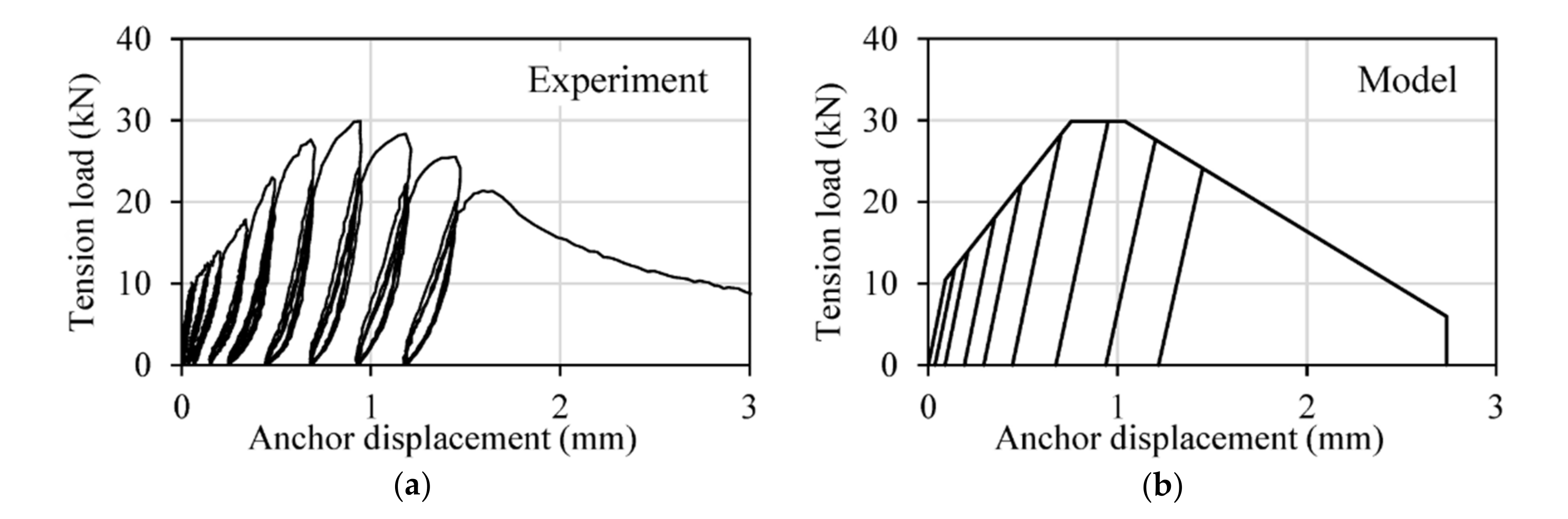
The proposed displacement-controlled procedure [32] is less focused on the residual capacity of an anchor after a seismic event but more on the actual hysteretic and displacement behavior in almost the complete range of the load–displacement curve. Similar to the test series C2.3 according to EOTA TR 049 [11], the input parameters that define the loading history are derived from static reference tests in cracked concrete. The first required displacement value is the mean displacement, su,m, corresponding to the ultimate loads obtained in the reference tests. The second value is smax, which is defined based on the post-peak behavior of the anchor. For post-installed anchors that show a rather brittle behavior, smax is determined as twice the displacement value corresponding to the ultimate load, 2 su. In the case of post-installed anchors that are able to develop ductility, indicated by a more pronounced post-peak behavior, smax is determined as the mean displacement corresponding to the point when 80% of the ultimate load is reached in the post-peak range of the load–displacement curve, s80%Nu:
Note that the displacement value smax is rather similar to the displacement limit used for seismic qualification of post-installed rebar following EAD 331522 [36].
Figure 5 shows the loading history. As can be seen, the protocol is displacement-controlled and comprises nine stepwise increasing displacement levels and a residual pullout test after completion of the cyclic loading history. In the first six levels, the displacement is stepwise increased with the displacement su,m being applied in the sixth level. The first six levels correspond to 10%, 20%, 30%, 50%, 70%, and 100% of su,m. Subsequently follow another three displacement levels that are intended to cover the post-peak range of the load–displacement curve. These three levels are equally spaced between su,m and smax. The exact displacement values for level seven and level eight can be calculated as:
The displacement corresponding to the final level is smax. Following the cyclic loading history, a residual static pullout test is performed. However, it should be noted that the purpose of this residual pullout test is not to determine the residual tension capacity of the anchor but to bring it to failure and to obtain the complete load–displacement curve. In contrast to the procedure for pulsating tension load according to the C2.3 protocol, where the minimum number of load cycles is five, the anchor displacement is cycled three times at each level. Details of the test procedure are given in [32].
4.2. Use in Performance-Based Design for Anchors
Displacement-controlled procedures, such as the one discussed above, provide a way to obtain additional information that is required for an accurate description of the cyclic anchor behavior. In Figure 6a, a typical result for a single bonded anchor (M16, hef = 80 mm, C20/25, Δw = 0.8 mm) subjected to the displacement-controlled protocol is shown. The information obtained from this protocol, such as the unloading and reloading stiffness and the residual displacements, can be used to model the hysteretic anchor behavior as indicated in Figure 6b. In such a model, the envelope of the load–displacement curve is idealized using a pentalinear format [9,37,38] and the hysteretic behavior is based on the Pivot Hysteresis Model [39].
5. Summary and Closing Remarks
The development of the testing procedures in category C2 was initially focused on post-installed anchors used to attach non-structural elements to the primary structure. In this regard, the information that can be obtained from these procedures is suitable for a safe design in non-structural applications under severe seismic actions. Additionally, when post-installed anchors are used in certain structural applications, such as the connection of secondary structural elements that are not part of the load-transfer mechanism against seismic loads, the testing procedures cover a sufficient part of the load–displacement curve to obtain the required information for a safe design. On the other hand, when post-installed anchors are used to form the connection between primary structural elements, that is, the elements that are part of the load-transfer mechanism against seismic loads, the demands are significantly higher. Examples for such applications are the attachment of steel bracings [8] or haunch elements [1]. In these kinds of applications, it may not be possible to guarantee that the anchors will remain within the linear elastic range. Here, the information on the hysteretic and displacement behavior of the anchor in the pre-peak range of the load–displacement curve alone may not be sufficient to judge the adequacy of the anchor performance reliably. Additional tests, such as the described displacement-controlled test for pulsating tension load, can then be performed to obtain information on the hysteretic behavior at ultimate load and even in the post-peak range.
Likewise, certain design criteria for seismic connections in EN 1992-4 [12] recommend the formation of a plastic hinge in the fixture. In such a design case, it is essential to consider additional aspects such as the redistribution of forces to the individual anchors of a group. This requires a non-linear design approach that directly accounts for the behavior of the fixture and the displacement and hysteretic behavior of individual types of anchors. The appropriate information can be obtained from additional qualification tests that focus more on the non-linear behavior of the anchor during a seismic event than on their residual capacity. Testing guidelines for concrete structural members such as ACI 374.2R-13 [3], which recommend displacement-controlled testing procedures to obtain the information on the non-linear seismic behavior of the structural members, could serve as an example and help to develop those new approaches.
The maximum considered crack width in the current qualification tests is Δw = 0.8 mm, which is based on the specifications in EOTA TR 049 [11], limiting the use of post-installed anchors to areas outside of plastic hinge zones. In the case of non-structural applications or secondary structural applications where the location of the connection can be chosen accordingly, the 0.8 mm limit for crack width is deemed adequate for safe design. However, in certain seismic strengthening solutions, the concept of the strengthening requires relocation of the plastic hinge rather close to the location of the anchors, for example in the case of steel haunches [1]. This solution aims at preventing a brittle failure in beam-column joints by shifting the failure to the beams where the behavior is significantly more ductile. In such a connection, the anchors will be located relatively close to the expected plastic hinge in the beams and crack widths larger than 0.8 mm might be expected. A qualification test, for example, where the anchor is not tested until reaching a certain crack width, as is the case for the C2.5 tests, but where the anchor is subjected to stepwise increasing crack widths until failure, may provide additional information to the already existing testing procedures and help guarantee a safe design.
In this context, the pass or fail criteria in the current guideline may not be sufficient to determine the anchor performance in certain applications. With regard to performance-based design and non-linear modeling of connections, it is vital to have additional information on the stiffness degradation, residual displacements, and strength degradation in subsequent cycles of a displacement level in a broader range of the load–displacement curve.
Author Contributions
Conceptualization, E.J.S. and A.S.; methodology, E.J.S.; validation, E.J.S. and A.S.; investigation, E.J.S.; writing—original draft preparation, E.J.S.; writing—review and editing, A.S.; visualization, E.J.S.; supervision, A.S.; project administration, E.J.S.; funding acquisition, A.S. All authors have read and agreed to the published version of the manuscript.
Funding
This research received no external funding.
Acknowledgments
The authors wish to thank fischerwerke GmbH & Co. KG for their support. All opinions, conclusions, and recommendations expressed in this paper are those of the authors and do not necessarily reflect those of the sponsoring organization.
Conflicts of Interest
The authors declare no conflict of interest.
References
- Sharma, A.; Reddy, G.R.; Eligehausen, R.; Genesio, G.; Pampanin, S. Seismic response of RC frames with haunch retrofit solution. ACI Struct. J. 2014, 111, 673–684. [Google Scholar] [CrossRef]
- Mahadik, V.; Sharma, A. Bidirectional Loading History for Seismic Testing of 3D Frame Joints. Civil Eng. 2021, 2, 349–369. [Google Scholar]
- ACI 374.2R-13. Guide for Testing Reinforced Concrete Structural Elements under Slowly Applied Simulated Seismic Loads; American Concrete Institute: Farmington Hills, MI, USA, 2013. [Google Scholar]
- Fabbrocino, F.; Farina, I.; Modano, M. Loading noise effects on the system identification of composite structures by dynamic tests with vibrodyne. Compos. Part B-Eng. 2017, 115, 376–383. [Google Scholar] [CrossRef]
- Papalou, A. Strengthening of masonry structures using steel frames. Int. J. Eng. Technol. 2013, 2, 50–56. [Google Scholar] [CrossRef] [Green Version]
- Casalegno, C.; Russo, S.; Sciarretta, F. Numerical Analysis of a Masonry Panel Reinforced with Pultruded FRP Frames. Mech. Compos. Mater. 2018, 54, 207–220. [Google Scholar] [CrossRef]
- Eligehausen, R.; Mallee, R.; Silva, J.F. Anchorage in Concrete Construction, 1st ed.; Ernst & Sohn: Berlin, Germany, 2006. [Google Scholar]
- Mahrenholtz, C.; Lin, P.C.; Wu, A.C.; Tsai, K.C.; Hwang, S.J.; Lin, R.Y.; Bhayusukma, M.Y. Retrofit of reinforced concrete frames with buckling-restrained braces. Earthq. Eng. Struct. Dyn. 2015, 44, 59–78. [Google Scholar] [CrossRef]
- Sharma, A. Seismic Behavior and Retrofitting of RC Frame Structures with Emphasis on Beam-Column Joints–Experiments and Numerical Modeling. Ph.D. Thesis, University of Stuttgart, Stuttgart, Germany, 2013. [Google Scholar]
- Mazzolani, F.M.; Della Corte, G.; D’Aniello, M. Experimental analysis of steel dissipative bracing systems for seismic upgrading. J. Civ. Eng. Manag. 2009, 15, 7–19. [Google Scholar] [CrossRef] [Green Version]
- EOTA TR 049. Technical Report 049:2016-08 Post-Installed Fasteners in Concrete under Seismic Action; European Organisation for Technical Assessment: Brussels, Belgium, 2016. [Google Scholar]
- EN 1992-4. Eurocode 2: Design of Concrete Structures–Part. 4: Design of Fastenings for Use in Concrete, English version EN 1992-4:2018 (E); European Committee for Standardization: Brussels, Belgium, 2018. [Google Scholar]
- EN 1998-1. Eurocode 8: Design of Structures for Earthquake Resistance–Part. 1: General Rules, Seismic Actions and Rules for Buildings; Version EN 1998-1:2004 + AC; European Committee for Standardization: Brussels, Belgium, 2009. [Google Scholar]
- DIN EN 1992-4/NA. National Annex–Nationally Determined Parameters–Eurocode 2: Design of Concrete Structures–Part. 4: Design of Fastenings for Use in Concrete, German version DIN EN 1992-4/NA: 2019-04; European Committee for Standardization: Brussels, Belgium, 2019. [Google Scholar]
- Lee, S.; Jung, W. Evaluation of Structural Performance of Post-Installed Anchors Embedded in Cracked Concrete in Power Plant Facilities. Appl. Sci. 2021, 11, 3488. [Google Scholar] [CrossRef]
- Muciaccia, G.; Marchisella, A. A review of existing provisions for seismic qualification and design of post-installed fasteners. In Proceedings of the 3rd International Symposium on Connections between Steel and Concrete, Stuttgart, Germany, 27–29 September 2017; Sharma, A., Hofmann, J., Eds.; IWB: Stuttgart, Germany, 2017. [Google Scholar]
- Hoehler, M.S. Behavior and Testing of Fastenings to Concrete for use in Seismic Applications. Ph.D. Thesis, University of Stuttgart, Stuttgart, Germany, 2006. [Google Scholar]
- Nuti, C.; Santini, S. Fastening technique in seismic areas: A critical review. In In Tailor Made Concrete Structures. In Proceedings of the International fib Symposium 2008, Amsterdam, The Netherlands, 19–21 May 2008; Walraven, J.C., Stoelhorst, D., Eds.; Taylor & Francis Group: London, UK, 2008; pp. 899–905. [Google Scholar]
- EN 1992-1. Eurocode 2: Design of Concrete Structures–Part. 1: General Rules and Rules for Buildings; EN 1992-1-1; European Committee for Standardization: Brussels, Belgium, 2004. [Google Scholar]
- Mahrenholtz, P.; Wood, R.L.; Eligehausen, R.; Hutchinson, T.C.; Hoehler, M.S. Development and validation of European guidelines for seismic qualification of post-installed anchors. Eng. Struct. 2017, 148, 497–508. [Google Scholar] [CrossRef]
- ACI 355.2. Qualification of Post-Installed Mechanical Anchors in Concrete (355.2-07) and Commentary; American Concrete Institute: Farmington Hills, MI, USA, 2007. [Google Scholar]
- ACI 355.4. Acceptance Criteria for Qualification of Post-Installed Adhesive Anchors in Concrete (ACI 355.4-11) and Commentary; American Concrete Institute: Farmington Hills, MI, USA, 2007. [Google Scholar]
- Silva, J.F. Test methods for seismic qualification of post-installed anchors. In Connections between Steel and Concrete; In Proceedings of the International Symposium of Steel and Concrete, Stuttgart, Germany, 10–12 September 2001; RILEM Publications: Cachan, France, 2001; pp. 551–563. [Google Scholar]
- Mahrenholtz, P.; Eligehausen, R.; Hutchinson, T.C.; Hoehler, M.S. Behavior of Post-Installed Anchors Tested by Stepwise Increasing Cyclic Load Protocols. ACI Struct. J. 2016, 113, 997–1008. [Google Scholar] [CrossRef] [PubMed] [Green Version]
- Sharma, A.; Mahrenholtz, C.; Eligehausen, R.; Reddy, G.R.; Vaze, K.K.; Ghosh, A.K.; Kushwaha, H.S. Evaluation of Load on Anchor for Concrete Structures Corresponding to Maximum Crack Width–A Probabilistic Approach. Int. J. Earth Sci. Eng. 2010, 3, 798–811. [Google Scholar]
- Mahrenholtz, P.; Eligehausen, R. Anchor Displacement Behavior during Simultaneous Load and Crack Cycling. ACI Struct. J. 2016, 113, 645–652. [Google Scholar] [CrossRef]
- Sharma, A.; Mahadik, V.; Hofmann, J. Influence of Tension Loading Protocol on Crack Cycling Tests on Undercut Anchors. ACI Struct. J. 2016, 113, 779–790. [Google Scholar] [CrossRef]
- Zeman, O.; Guggenberger, T.; Bergmeister, K.; Zimmermann, T. Versuchstechnische Bestimmung der Eignung von Befestigungssystemen unter seismischer Beanspruchung. Beton Stahlbetonbau 2015, 110, 281–292. [Google Scholar] [CrossRef]
- Hoehler, M.S.; Eligehausen, R. Behavior and Testing of Anchors in Simulated Seismic Cracks. ACI Struct. J. 2008, 105, 348–357. [Google Scholar]
- EAD 330232. EAD 330232-00-0601 Mechanical Fasteners for Use in Concrete; European Organisation for Technical Assessment: Brussels, Belgium, 2016. [Google Scholar]
- EAD 330499. EAD 330499-00-0601 Bonded Fasteners for Use in Concrete; European Organisation for Technical Assessment: Brussels, Belgium, 2017. [Google Scholar]
- Stehle, E.J.; Sharma, A. A new displacement-based approach for pulsating tension load tests of post-installed anchors for the use in structural applications under seismic actions. Eng. Struct. 2020, 211, 110431. [Google Scholar] [CrossRef]
- ETAG 001, Part 1. Guideline for European Technical Approval of Metal Anchors for Use in Concrete, Part. 1; European Organization of Technical Approvals (EOTA): Brussels, Belgium, 1997. [Google Scholar]
- Sharma, A. Urgent need for a performance-based approach for seismic assessment and design of fastenings used in structural applications. Adv. Civil. Eng. Technol. 2019, 3. [Google Scholar] [CrossRef]
- Sharma, A. Performance based approach for anchorage in concrete construction. In Proceedings of the 3rd International Symposium on Connections between Steel and Concrete, Stuttgart, Germany, 27–29 September 2017; Sharma, A., Hofmann, J., Eds.; IWB: Stuttgart, Germany, 2017. [Google Scholar]
- EAD 331522. EAD 331522-00-0601 Post-Installed Rebar with Mortar under Seismic Action; European Organisation for Technical Assessment: Brussels, Belgium, 2018. [Google Scholar]
- Bokor, B.; Sharma, A.; Hofmann, J. Spring modelling approach for evaluation and design of tension loaded anchor groups in case of concrete cone failure. Eng. Struct. 2019, 197, 109414. [Google Scholar] [CrossRef]
- Hofmann, J.; Mahadik, V.; Sharma, A. Modelling Structure-Anchor-Component Interaction for Nuclear Safety Related Structures Under Seismic Loads–Part 2: Development of Numerical Model. In Proceedings of the 23rd International Conference on Structural Mechanics in Reactor Technology, Manchester, UK, 10–14 August 2015; Curran Associates, Inc.: Red Hook, NY, USA, 2017. [Google Scholar]
- Dowell, R.K.; Seible, F.; Wilson, E.L. Pivot Hysteresis Model for Reinforced Concrete Members. ACI Struct. J. 1998, 95, 607–617. [Google Scholar]
Figure 1.
Connections between structural steel elements and RC structures: (a) steel bracing to RC frame; (b) steel haunches to RC frame; (c) steel column to foundation.
Figure 1.
Connections between structural steel elements and RC structures: (a) steel bracing to RC frame; (b) steel haunches to RC frame; (c) steel column to foundation.

Figure 2.
Schematic test procedure for pulsating tension load tests in test series C2.3. Redrawn on the basis of EOTA TR 049 [11].
Figure 2.
Schematic test procedure for pulsating tension load tests in test series C2.3. Redrawn on the basis of EOTA TR 049 [11].

Figure 3.
Schematic test procedure for alternating shear load tests in test series C2.4. Redrawn on the basis of EOTA TR 049 [11].
Figure 3.
Schematic test procedure for alternating shear load tests in test series C2.4. Redrawn on the basis of EOTA TR 049 [11].

Figure 4.
Schematic test procedure for crack cycling tests in test series C2.5. Redrawn on the basis of EOTA TR 049 [11].
Figure 4.
Schematic test procedure for crack cycling tests in test series C2.5. Redrawn on the basis of EOTA TR 049 [11].

Figure 5.
Schematic test procedure for the displacement-controlled protocol. Redrawn on the basis of [32].
Figure 5.
Schematic test procedure for the displacement-controlled protocol. Redrawn on the basis of [32].

Figure 6.
Load–displacement curves of: (a) a single bonded anchor (M16, hef = 80 mm, C20/25, Δw = 0.8 mm) subjected to the displacement-controlled loading protocol for pulsating tension load; (b) idealization of the cyclic behavior of a single anchor.
Figure 6.
Load–displacement curves of: (a) a single bonded anchor (M16, hef = 80 mm, C20/25, Δw = 0.8 mm) subjected to the displacement-controlled loading protocol for pulsating tension load; (b) idealization of the cyclic behavior of a single anchor.


Table 1.
Summary of required tests for category C2.
| Test Series | Test Type | Load | Crack width Δw (mm) | Total Number of Cycles |
|---|---|---|---|---|
| C2.1 | Reference tension tests | Until failure | 0.8 | – |
| C2.2 | Reference shear tests | Until failure | 0.8 | – |
| C2.3 | Pulsating tension load | Nmax = 0.75 Nu,m,C2.1 | 0.5 (N/Nmax ≤ 0.5) 0.8 (N/Nmax > 0.5) | 75 |
| C2.4 | Alternating shear load | Vmax = 0.85 Vu,m,C2.2 | 0.8 | 75 |
| C2.5 | Crack cycling | Nw1 = 0.4 Nu,m,C2.1 Nw2 = 0.5 Nu,m,C2.1 | 0.0–0.8 | 59 |
Publisher’s Note: MDPI stays neutral with regard to jurisdictional claims in published maps and institutional affiliations. |
© 2021 by the authors. Licensee MDPI, Basel, Switzerland. This article is an open access article distributed under the terms and conditions of the Creative Commons Attribution (CC BY) license (https://creativecommons.org/licenses/by/4.0/).
Share and Cite
MDPI and ACS Style
Stehle, E.J.; Sharma, A. Review of Testing and Qualification of Post-Installed Anchors under Seismic Actions for Structural Applications. CivilEng 2021, 2, 406-420. https://0-doi-org.brum.beds.ac.uk/10.3390/civileng2020023
AMA Style
Stehle EJ, Sharma A. Review of Testing and Qualification of Post-Installed Anchors under Seismic Actions for Structural Applications. CivilEng. 2021; 2(2):406-420. https://0-doi-org.brum.beds.ac.uk/10.3390/civileng2020023
Chicago/Turabian StyleStehle, Erik Johannes, and Akanshu Sharma. 2021. "Review of Testing and Qualification of Post-Installed Anchors under Seismic Actions for Structural Applications" CivilEng 2, no. 2: 406-420. https://0-doi-org.brum.beds.ac.uk/10.3390/civileng2020023