
Discrete Rigid Block Analysis to Assess Settlement Induced Damage in Unreinforced Masonry Façades


1
Durham School of Architectural Engineering and Construction, University of Nebraska-Lincoln, Omaha, NE 68182, USA
2
The Department of Civil and Environmental Engineering, Carleton University, Ottawa, ON K1S 5B6, Canada
3
School of Building Construction, Georgia Institute of Technology, Atlanta, GA 30332, USA
*
Author to whom correspondence should be addressed.
CivilEng 2021, 2(3), 541-555; https://0-doi-org.brum.beds.ac.uk/10.3390/civileng2030030
Submission received: 4 June 2021
/
Revised: 3 July 2021
/
Accepted: 7 July 2021
/
Published: 9 July 2021
(This article belongs to the Special Issue Damage Detection, Quantification and Modelling in Masonry Structures)
Abstract
:In this study, a system of discontinuous rigid blocks is employed to simulate the possible damage mechanisms in unreinforced masonry (URM) façades and load-bearing frame systems subjected to settlement using the discrete element method (DEM). First, the employed modeling strategy is validated utilizing the available experimental results presented in the literature. Once there is a good agreement between the computational models and experimental findings, a sensitivity analysis is performed to quantify the influence of the input parameters defined in the DEM-based numerical model. Finally, the proposed modeling strategy is further utilized to assess the damage pattern that may develop in a URM façade due to uniform and non-uniform settlement profiles. The results of this study clearly show that the discrete rigid block analysis (D-RBA) provides robust numerical solutions that can be employed to visualize and assess the possible damage patterns and related collapse mechanisms of URM masonry systems as an alternative modeling strategy to standard continuum-based solutions.
1. Introduction
Unreinforced masonry (URM) construction constitutes the vast majority of the world’s building stock, including historical structures worldwide. Although mechanical and thermal characteristics of masonry provide desirable construction features, it has a relatively weak tensile strength at mortar joints. This salient feature of masonry may yield local and global structural problems in masonry buildings, such as cracking, joint dislocation, and sliding failure in the load-bearing component of masonry structures (e.g., walls, arches, domes, etc.) throughout their service life. Additionally, extreme natural events (e.g., earthquakes and tornados), high-temperature fluctuations, and severe changes in boundary conditions (e.g., soil settlements and landslides) may trigger tension failure at the mortar joints and result in a partial or total collapse of masonry structures.
In this paper, settlement-induced damage progression (SIDP) in URM facades is studied using the discrete element method (DEM). This study demonstrates the possible crack patterns and failure modes of unreinforced masonry structures subjected to various forms of settlement.
The accuracy of the DEM models is ensured by comparing them to prior experimental results, resulting in an ability to test a large variety of scenarios. This, in turn, allows studying, in detail, the contribution of multiple variables (e.g., joint tensile strength and joint frictional resistance). As a result, the paper provides a better understanding of the cracking behavior and damage progression in masonry structures due to soil settlement.
Since the early 1980s, both experimental and computational works have been presented in the literature regarding settlement-induced failures in masonry structures. Boscardin et al. [1] used analytic models and field data to develop a procedure that helps evaluate the tolerance of a brick-bearing wall for settlement caused by tunneling. A homogeneous isotropic material behavior was assumed, and the brick-bearing wall was modeled as a linear-elastic deep beam. The ground deflections were imposed on the structure, and the critical tensile strain concept was used to evaluate the damage. The results showed that the tolerance to differential settlement decreases when a structure is subjected to increasing lateral strain, indicating buildings sited next to excavation are less tolerant than similar structures settling under their self-weight because of the lateral strain caused by responses from excavation. Burland and Wroth [2] discussed the damage in load-bearing brickwork walls due to settlement. Relative deflections were estimated based on the concept of critical tensile strain. Son et al. [3] performed damage assessment of brick-bearing, brick-infilled, and open-frame structures subjected to excavation-induced ground settlements. A two-dimensional (2D) discrete element method was utilized to simulate cracking in masonry units, and the emphasis was given to four-story structures on a shallow foundation. It was aimed to evaluate the elastic and non-linear response of the different structural types with different soil conditions (i.e., soft and stiff) considering progressive ground settlement. The results indicated that deriving conclusions by only looking at the elastic behavior of the structure can be misleading; thus, crack-induced damage progression and the soil-structure interaction phenomena should also be taken into account to obtain a better understanding of the relationship between structure and soil settlement. Recently, Camós et al. [4] analyzed the structural response of one-story masonry buildings affected by ground movements from L9 Metro tunnel construction in Barcelona. Two computational modeling strategies were utilized: the equivalent beam method and nonlinear finite element analysis (FEA). It was found that the largest plastic strain development occurs near the corners of doors and windows, where a high-stress concentration is expected. Furthermore, real tunnel-induced cracks obtained from the in situ damage survey were closely captured by evaluating the maximum crack openings determined by nonlinear FEA, demonstrated as diagonal and vertical cracks in windows and doors. Giardina et al. [5] performed a laboratory test carried out on a scaled masonry façade subjected to tunneling-induced settlements, where particular attention was given to the soil-structure interaction phenomena. The experiment reproduced a circular tunnel excavation in soft soil under a masonry structure. A pre-defined settlement profile was applied to a scaled building model by continuously monitoring the deflection and crack progression in the structure. The experiment showed that soil-structure interaction plays an important role in overall structural response because the stress redistribution within the façade depends on the relative stiffness between the façade and soil interface. In another recent research, interpreted crack patterns of masonry buildings subjected to landslide-induced settlements is analyzed using the load path method (LPM) by Palmisano [6]. The LPM searches for the load path that contains the lowest value of total strain energy instead of the exact path. Using macro-models obtained by the LPM, the structural behavior of the masonry walls subjected to landslides was evaluated.
In contrast to the existing literature summarized above, this study examines the cracking phenomenon in masonry walls via a discontinuum-based modeling approach where masonry units are represented as discrete (or distinct) rigid blocks, and mortar joints are replicated as zero-thickness interfaces. The described DEM-based analysis of masonry constructions has been used to assess various structures as discussed in a seminal article by Lemos [7].
First, the proposed modeling strategy is validated based on the small and large-scale experimental results, and then it is applied to assess a typical existing URM facade in downtown Omaha, Nebraska (United States). Once a validated model is established, a series of sensitivity analyses on the joint tensile strength and friction angle is performed. A brief background of DEM, validation of the computational approach, parametric analyses, and an application on real URM façade are presented in the following sections, respectively. Finally, the results are discussed, and necessary inferences are made regarding the damage progression and input material properties influencing the displacement response of masonry walls subjected to various forms of support settlement.
2. Computational Modeling Approach: Discrete Rigid Block Analysis (D-RBA)
Masonry is a highly non-linear, orthotropic, and heterogeneous material that makes it difficult to analyze accurately via simple methods. Moreover, frequently, the cracks are localized at the mortar joints, following a distinct crack propagation path. As a result of this, morphological features of masonry construction have an important role in the structural behavior and capacity of URM walls and other types of structural systems [8,9,10]. Although continuum-based solutions (e.g., standard FEA) provide valuable information about the capacity and smeared damage representation, more sophisticated algorithms or interface elements embedded into the FE model are required to obtain localized failures in FEA, as discussed in other studies [11,12,13]. Here, we propose an alternative approach, called discrete rigid block analysis (D-RBA), to simulate masonry façades based on the DEM. It should be noted that since the lack of tensile strength governs the examined collapse mechanism, no compression failure is implemented at the joints or within the blocks, as proven to be a valuable approach in previous studies [14,15,16].
The employed computational method is first developed by Cundall [17] to simulate jointed rock masses. In the last several decades, DEM has been used to analyze various masonry structures with different levels of complexity, considering deformable and rigid blocks in the material and structural level [18,19,20,21,22]. The main motivation of DEM is to simulate the interaction between regular or irregular-shaped blocks that go under large deformations using automatic contact detection algorithms to capture sliding, joint opening, and total contact loss. The numerical procedure of D-RBA relies on integrating translational and rotational equations of motions of rigid block center of mass. Note that a 3D rigid block has six degrees of freedom, three translational and three rotational. Simply, new velocities, evaluated at the end-points of the time step, are computed explicitly using the central difference method as given in Equations (1) and (2). The time step (∆t) is divided into mid-intervals and denoted as and . The quasi-static solutions are obtained by applying artificial damping to prevent any unnecessary noise in the solutions.
where , , ω, and are the displacement, force, angular velocity, and moment vectors. Moreover, , , and represent gravitational acceleration vector, the approximate moment of inertia, and the mass-propositional damping constant.
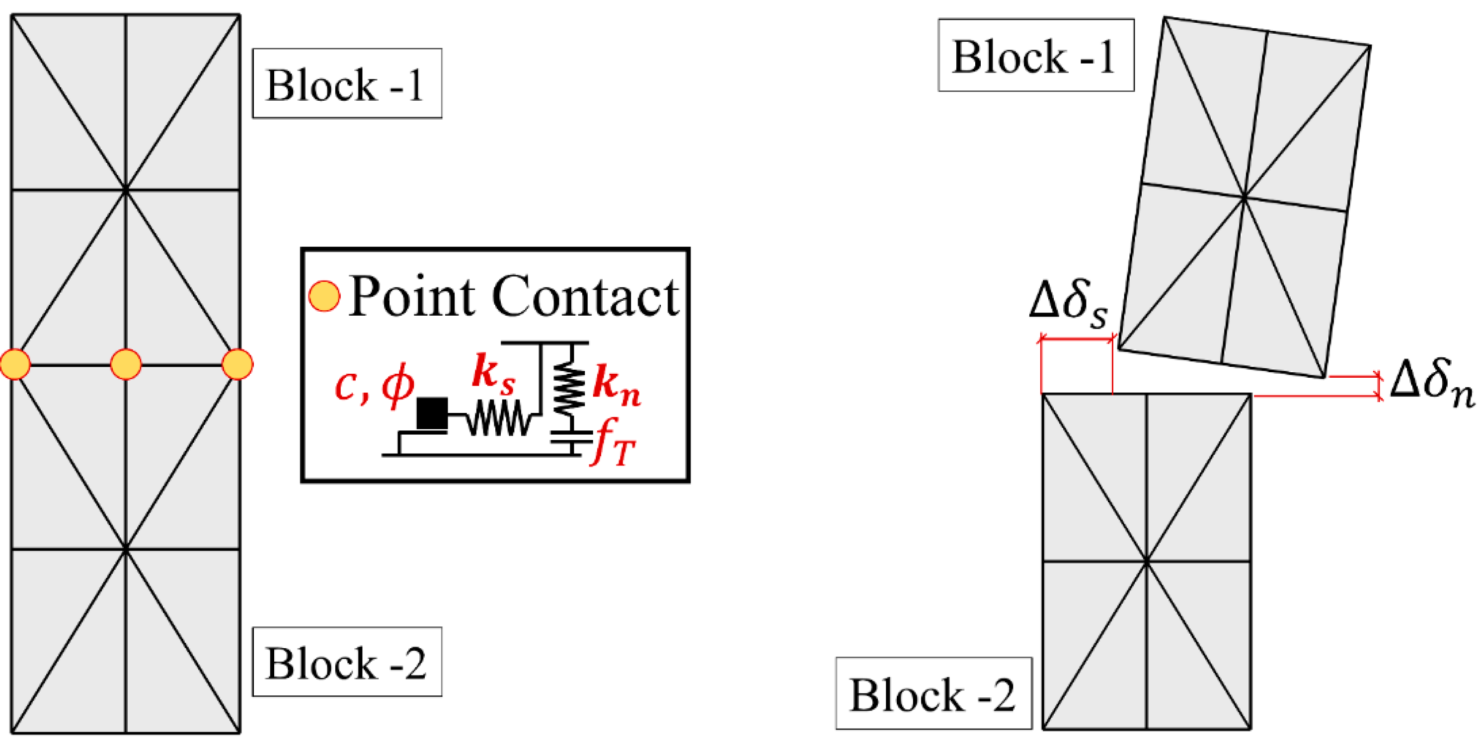
Once the new velocities are obtained, the block positions are updated based on the calculated translational and rotation increments (). Accordingly, relative point-contact displacements are determined among the adjacent blocks, where each point-contact orthogonal springs are defined, illustrated in Figure 1. In the normal direction, tensile strength is limited via pre-defined value (), whereas linearly elastic behavior is assumed in compression, as mentioned earlier. Coulomb slip-joint model is used in the shear direction, which requires contact friction angle and cohesion, denoted as and , respectively (Figure 1), to calculate the shear strength depending on the vertical stress ( at the joint (i.e., ). It is worth noting that the assigned normal () and shear () spring stiffnesses control elastic response at the joints, as well as the amount of overlapping between blocks (in compression). Note that the contact stress increments are computed utilizing the relative displacements between blocks (i.e., ,, see Figure 1) [23]. Then, the new contact stresses are obtained () and updated according to the considered contact constitutive model.
Finally, the contact stresses are multiplied with the assigned contact area to compute the forces employed in the equations of motions. Since the executed explicit computational procedure is conditionally stable, should be equal to or smaller than the critical time step () to keep the numerical stability during calculations. Here, the time step is determined as , considering a similar analogy to a simple degree of freedom system, suggested in [24]. Throughout this research, a commercial three-dimension discrete element code (3DEC-7.0), developed by ITASCA, is used [25]. In the next section, validation of the applied discontinuum-based modeling approach is presented.
3. Validation Studies
Two experimental studies, presented by Portioli and Cascini [26] and Giardina et al. [5], are utilized to validate our modeling strategy. A simple URM pier and spandrel system was tested in the former test, while in the latter, a scaled URM façade was built and exposed to non-uniform support settlement.
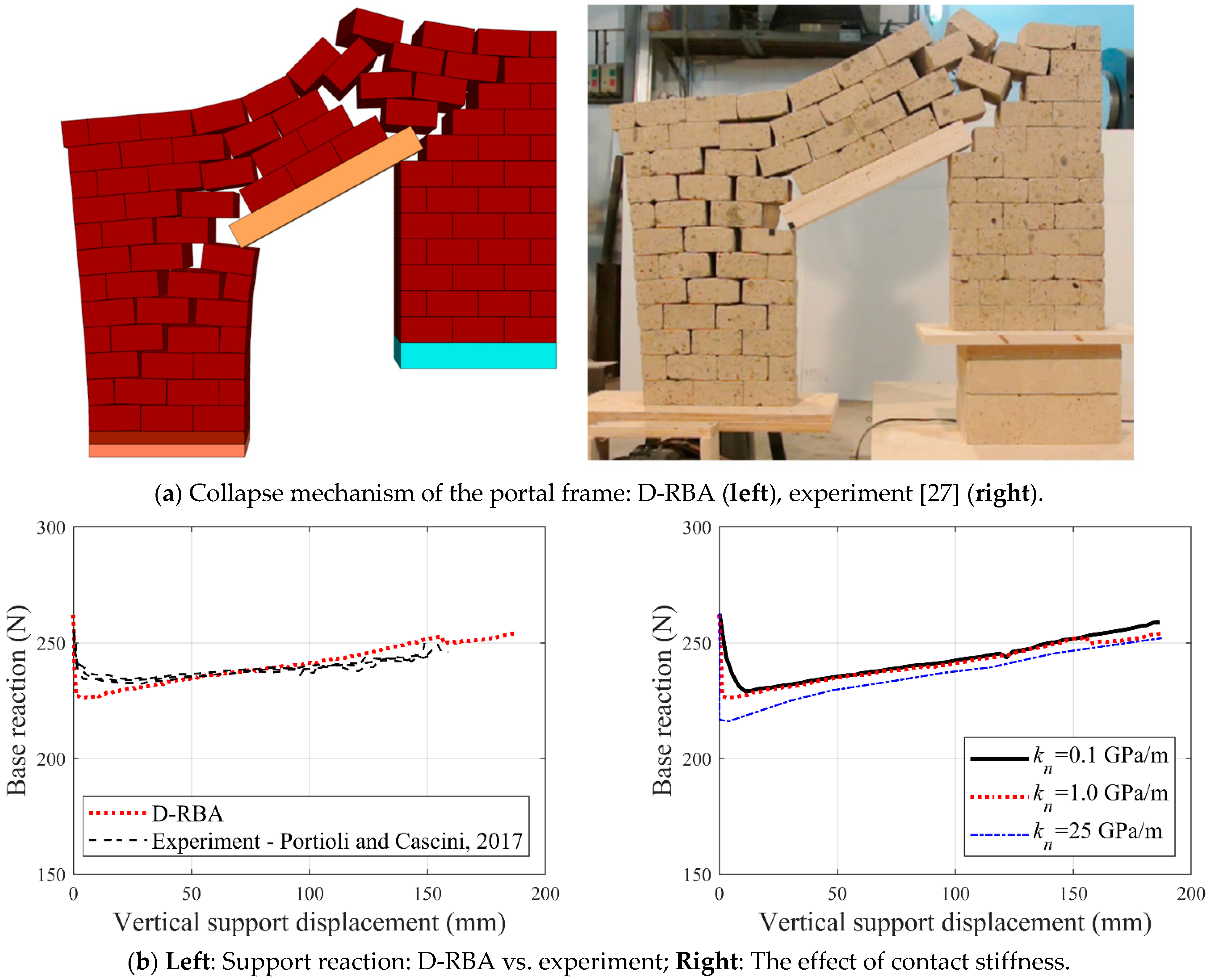
Validation Study—1: The small-scale dry-joint masonry portal frame, made up of tuff stones, was built and tested using vertically moving support by Portioli and Cascini [25]. It aimed to better understand the ultimate displacement and collapse mechanism of stone masonry portal frames exposed to support settlement. In the reference study, different boundary conditions (i.e., fixed and roller) were considered during the experimental campaign; however, only one of them (in which the moving support is fixed in the lateral direction) is employed in this study for validation purposes. The modeled portal frame comprises 12-courses in height and nine bricks in length with a three brick-length opening (brick dimension: 100 mm × 100 mm × 50 mm). Note that vertical displacement was imposed to the left masonry pier, where the supporting plate was restricted along the lateral direction, and supported reactions were monitored during the experiment. For further details regarding the test setup, the readers are referred to the reference study [26].
The applicable material properties (i.e., density and contact surface friction angle) are directly taken from the cited study, while the contact stiffness () is predicted as 1 GPa/m, and the normal to shear stiffness ratio is taken as 0.4. As shown in Figure 2, the applied discontinuum-based rigid block approach provides good predictions in terms of collapse mechanism (Figure 2a) and force-reaction, recorded at the base of the settled masonry pier (see Figure 2b-left). Additionally, a sensitivity analysis is performed by considering similar discontinuum-models in the literature (e.g., [27,28]) to better observe the influence of contact stiffness. The results show parallel base reactions together with no considerable structural behavior difference. A smoother base reaction vs. vertical displacement curve is obtained for a lower stiffness ( GPa/m), whereas relatively sudden reaction change (in other words, more brittle macro behavior) is observed for a higher stiffness ( GPa/m), given in Figure 2b-right.
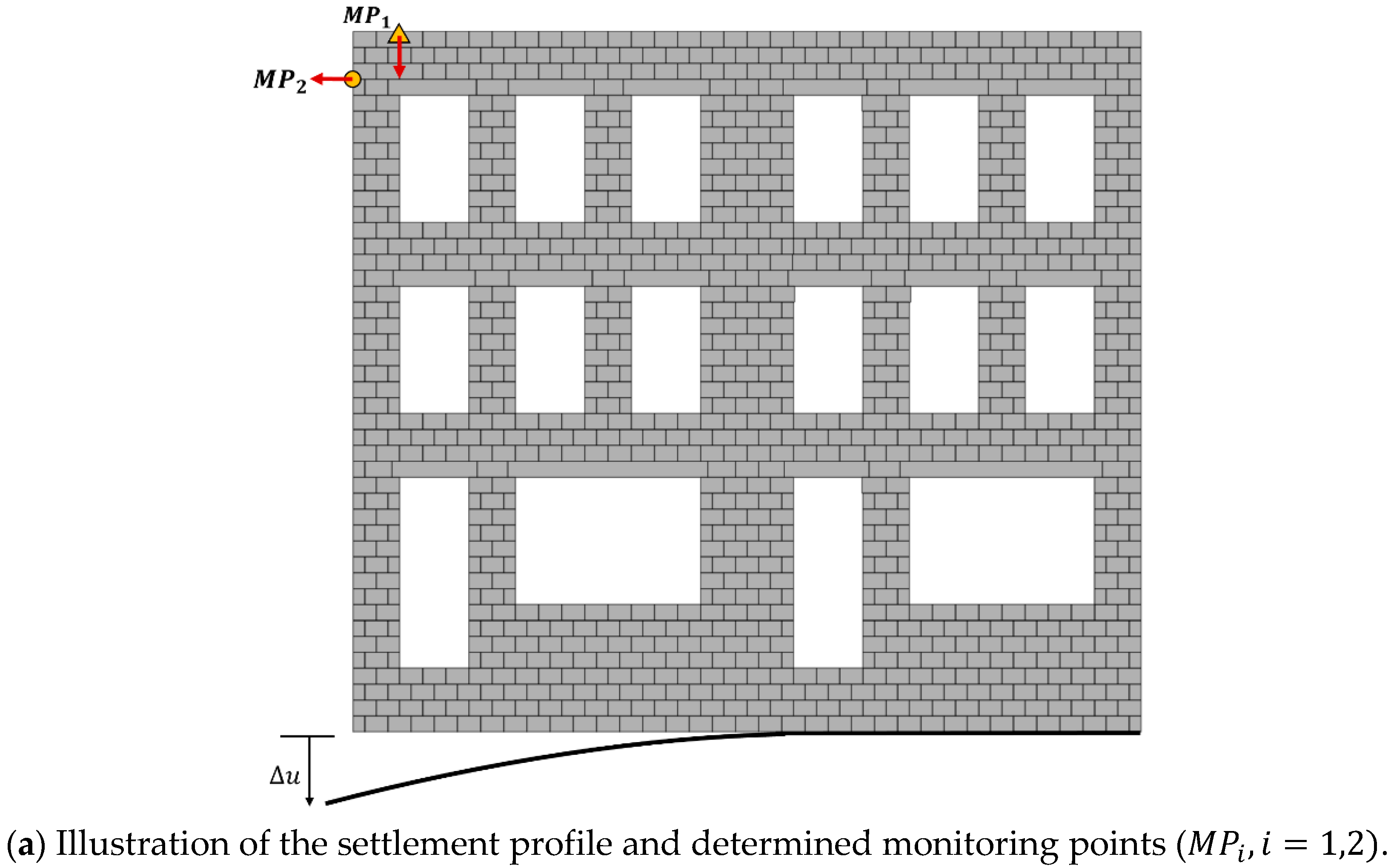
Validation Study—2: Once the D-RBA is validated on a small-scale pier-spandrel system, a more complex structural configuration is analyzed (Figure 3a). A recent experimental work presented by Giardina et al. [5] is utilized to validate our computational approach where the tunneling-induced settlement effects on masonry façades were investigated. The experiment was set up to replicate the event, where a circular tunnel being excavated in soft soil under a masonry structure on a wooden pile foundation. The structure was located in the hogging zone of the tunnel-induced settlement profile (downward concavity). Note that a 1/10th scaled masonry façade was constructed with 1010 scaled solid bricks (dimensions of 25 mm × 40 mm × 50 mm) and 2 mm thick layers of low strength lime mortar. The base of the scaled masonry façade was connected to a flexible steel profile to be able to control the settlement beneath the structure. The interface stiffness was taken into account by simulating soil-structure interaction by inserting rubber between the masonry façade and the steel profile. Several monitoring points on the façade were monitored during the experiment to trace the lateral and vertical deformations, as illustrated in Figure 3.
First, dead loads (self-weight + floor loads) were applied (readers referred to reference study for further details). Then, the steel profile was adjusted in 23 steps of 0.5 mm, reaching a final displacement of 11.5 mm on the scaled model. The settlement profile is represented by the gaussian error function presented by Peck [29] given in Equation (3).
where is the maximum settlement measured above the tunnel axis, is the horizontal distance from the tunnel axis and denotes the horizontal distance between the vertical tunnel axis and the point of inflection.
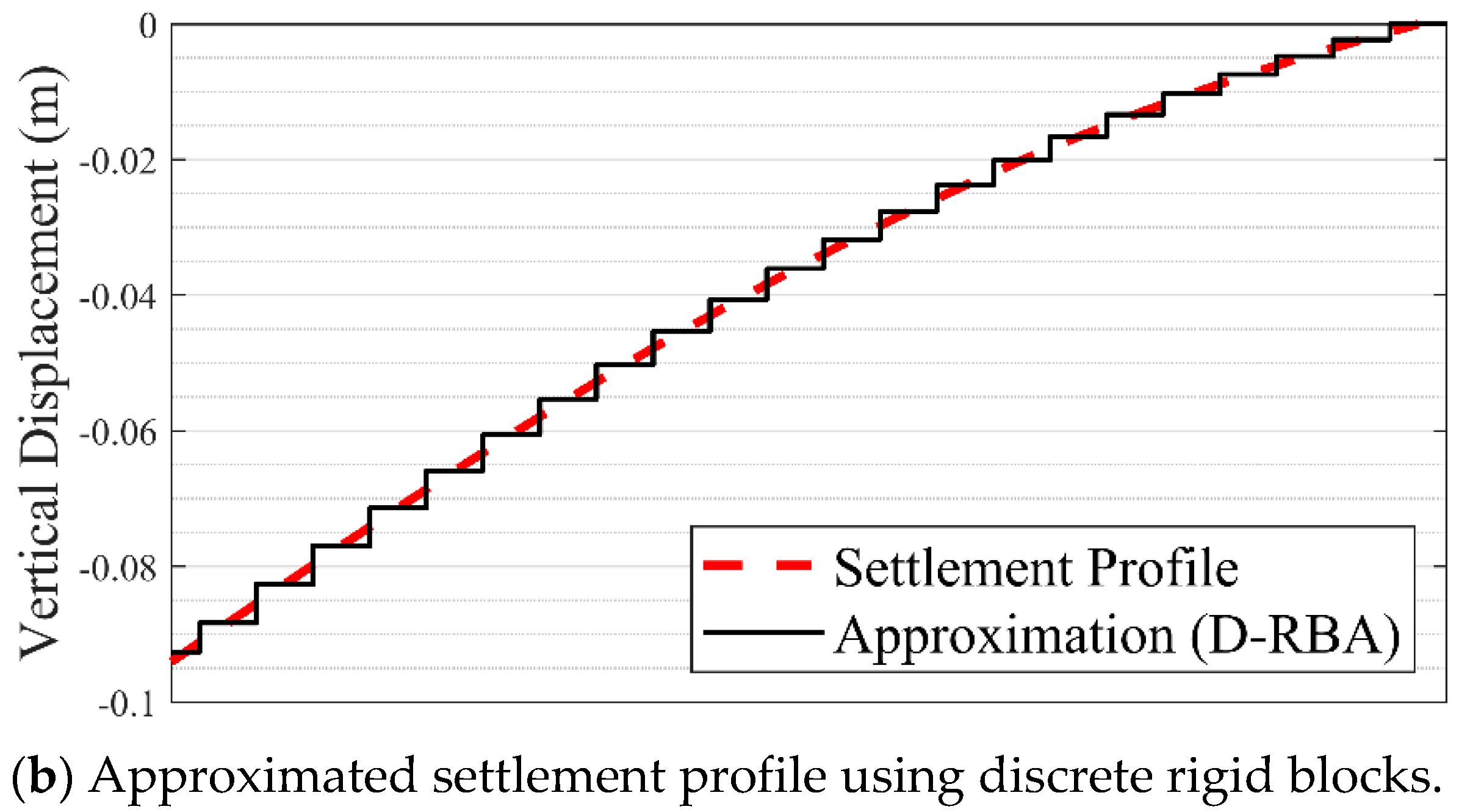
Here, is taken as 8 m, determined by Giardina et al. [5]. The same loading procedure (i.e., dead load + support settlement) is followed through the discrete rigid block analysis. It is worth noting that in the discontinuum-based model, the continuous settlement profile is replaced with a series of discrete vertical displacements, which are defined for each support block as demonstrated in Figure 3b. Once the support settlement profile is determined, the vertical velocity is prescribed to the corresponding support blocks with a very low displacement rate to obtain quasi-static solutions from the motion equations, as explained in the previous section. The contact properties are determined in line with the reference study, where joint tensile strength, cohesion, and friction angle are defined as 0.1 × 10⁶ Pa, 0.15 × 10⁶ Pa, and 35 degrees, respectively, whereas the contact stiffness is assumed 11 GPa/m, determined via sensitivity analysis as performed in the previous validation study with the same normal to shear stiffness ratio.
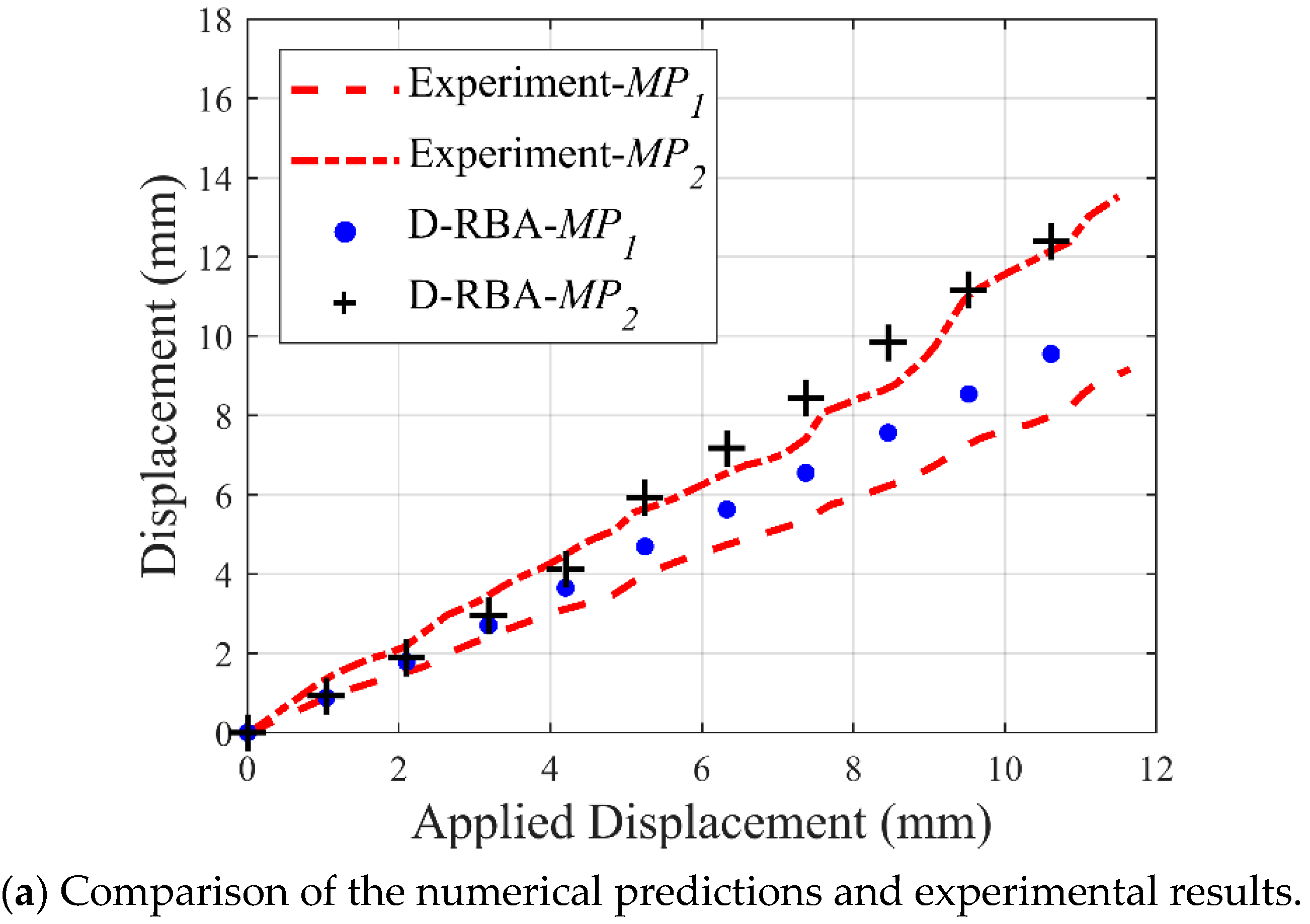
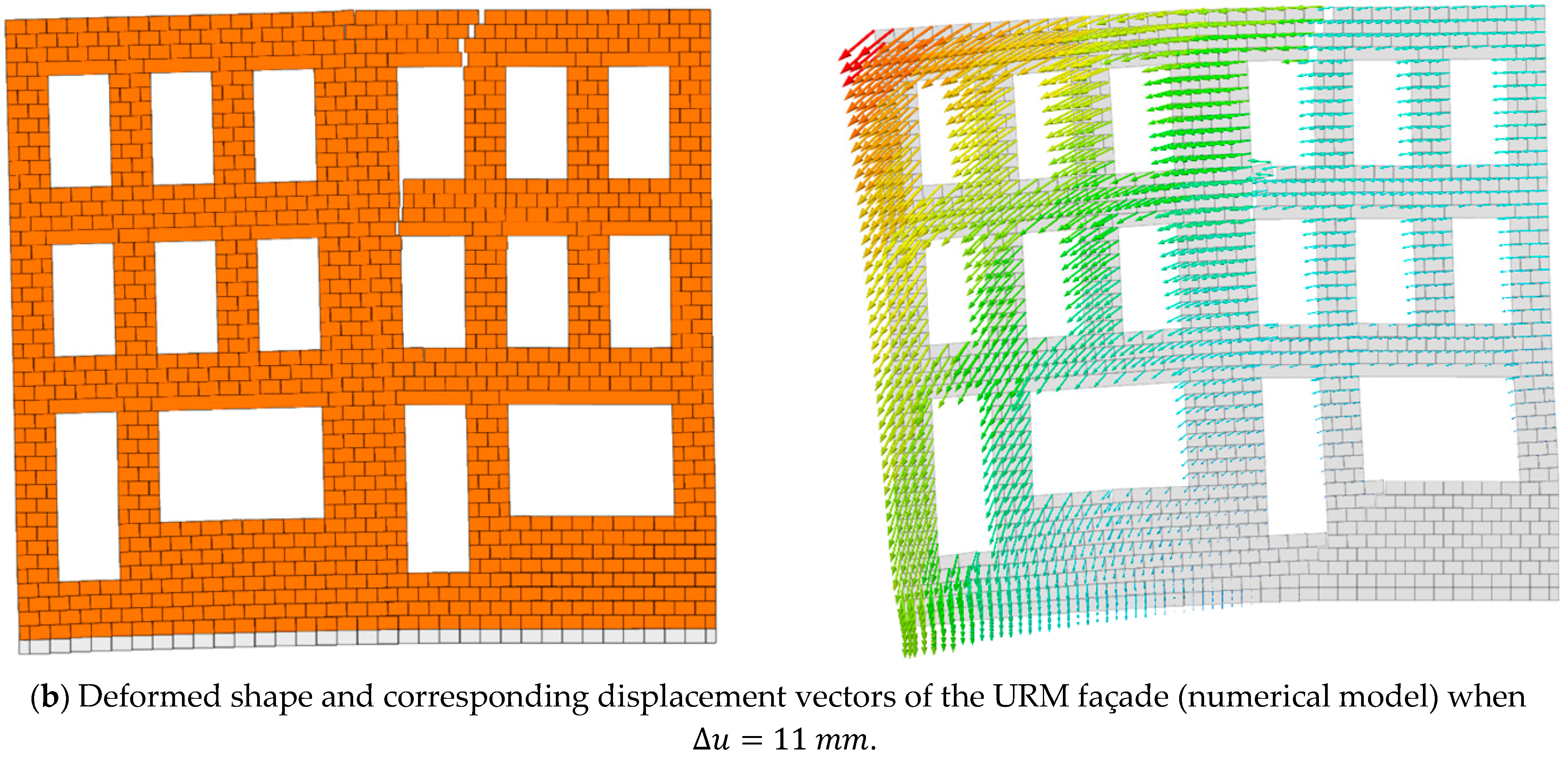
The discrete rigid block models show similar trends compared to the experimental results given in Figure 4. The outcomes of this validation study show a strong similarity between the horizontal and vertical displacement histories, recorded from monitoring points ( and ), see Figure 4a. Moreover, observed crack pattern and global structural mechanism obtained from D-RBA exhibit parallel behavior compared to experimental findings presented in the reference study [5].
4. Parametric Analysis
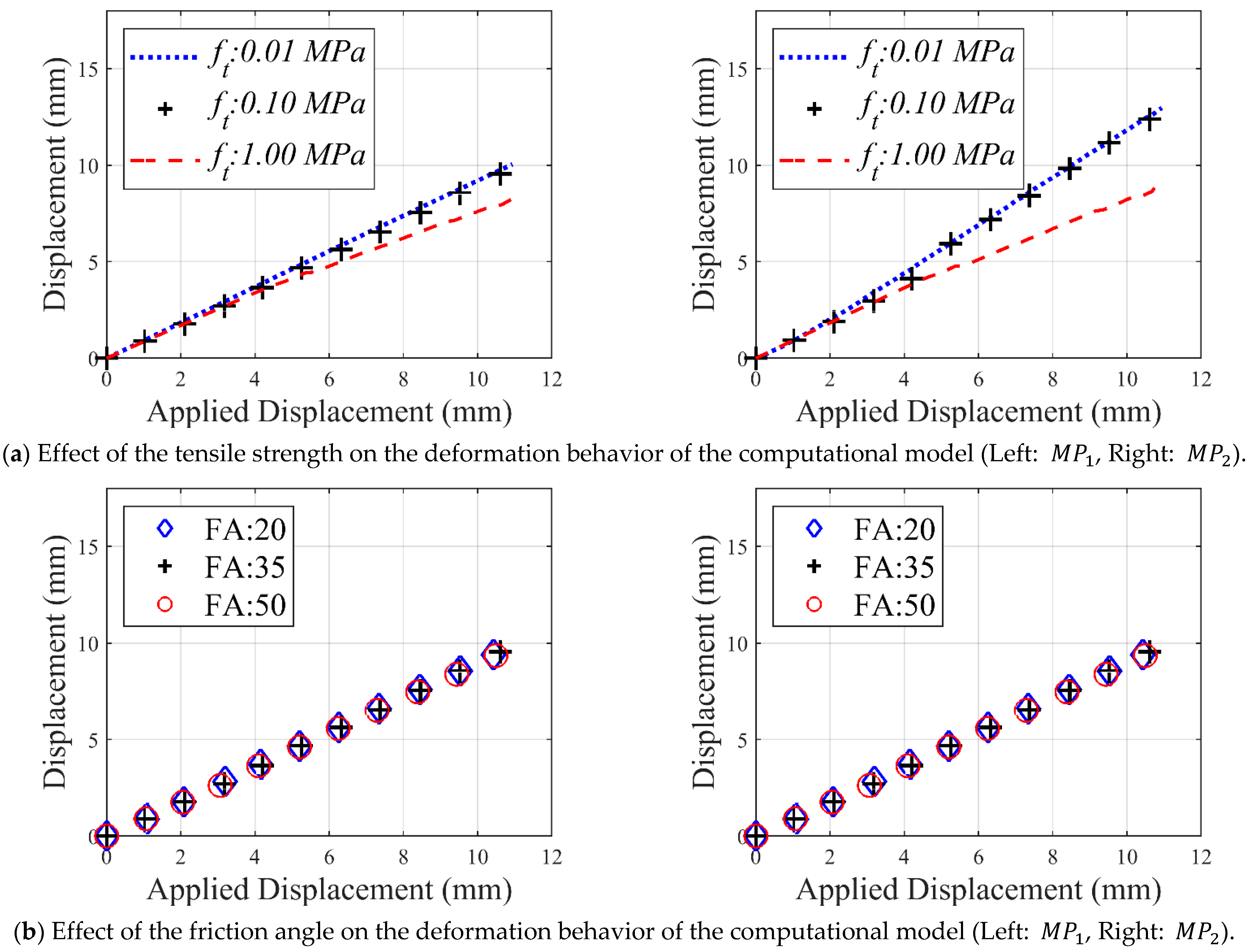
In this section, a sensitivity analysis is performed to better understand the effect of two essential input parameters: joint tensile strength () and the friction angle (), used in the D-RBA. It is important to note that the ratio of cohesion to tensile strength kept constant as 1.5 during the parametric analysis, in line with the other studies [30,31].
Results show that tensile and frictional resistance affect the displacement at different magnitudes, as depicted in Figure 5. The change in friction angle from 20 degrees to 50 degrees only causes a 6% decrease in horizontal deflection, while changing tension from 0.01 MPa to 1 MPa causes a 29% percent decrease. Overall, it is important to note that horizontal deflection connected to change in tension is around 6% less than horizontal deflection connected to a change in frictional angle. Vertical displacement only decreased by 1% when changing the friction angle from 20 degrees to 50 degrees and 7% when changing tension from 0.01 MPa to 1 MPa. Hence, the sensitivity analysis results suggest that the joint tensile strength has a much larger influence on the results because the forces acting upon the mortar joints trigger a rapid tensile failure and yield different force-distribution paths at the joints. This finding also means that tensile failure becomes dominant over shear failure (sliding), which further underlines the importance of contact parameters on the structural response. Therefore, reliable data regarding the joint strength and quality are necessary as inputs for the computational models to obtain accurate predictions of structural behavior.
5. Applications of the D-RBA: Crack Patterns in URM Façade
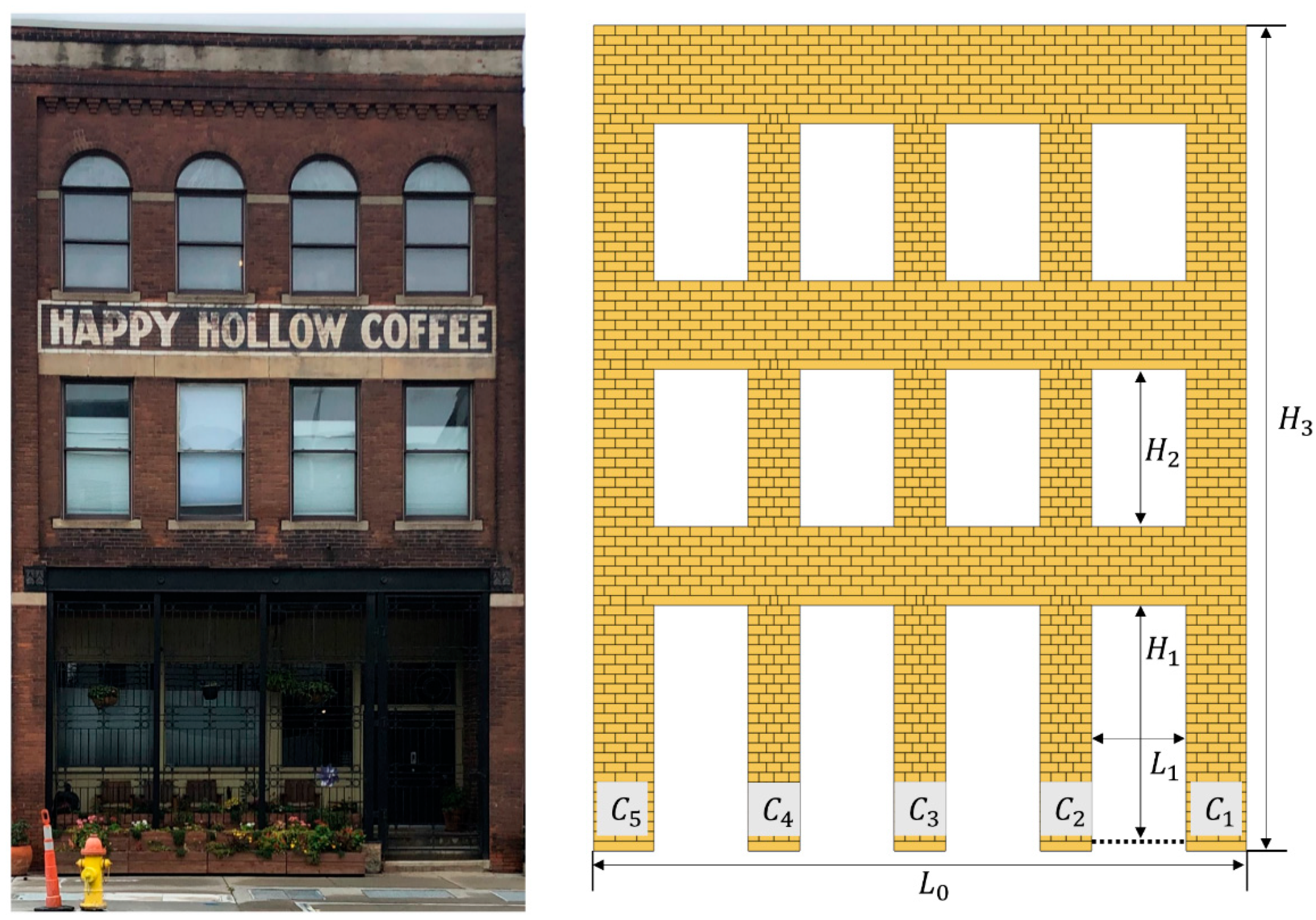
In this section, the validated modeling strategy is applied to observe the possible crack patterns that can develop in a URM Façade with low-bond joint tensile strength. First, a hypothetical clay brick masonry façade is generated, inspired by a typical 19–20th century historic residential building located in the downtown area of Omaha, Nebraska, United States (Figure 6). The geometrical features are approximately measured based on the structural survey, where inner and outer column widths are determined as 0.65 and 0.75 m, respectively. The openings are regular, and the structure is symmetric along the vertical axis (further details regarding the geometrical properties can be found in Figure 6). Moreover, the material and contact properties, given in Table 1, are determined based on the related previous studies [15,16,32,33]. Note that only the self-weight of the structure is taken into account since the motivation of this research is to assess the failure mechanism due to support settlement, which is not affected by applied floor loads [34].
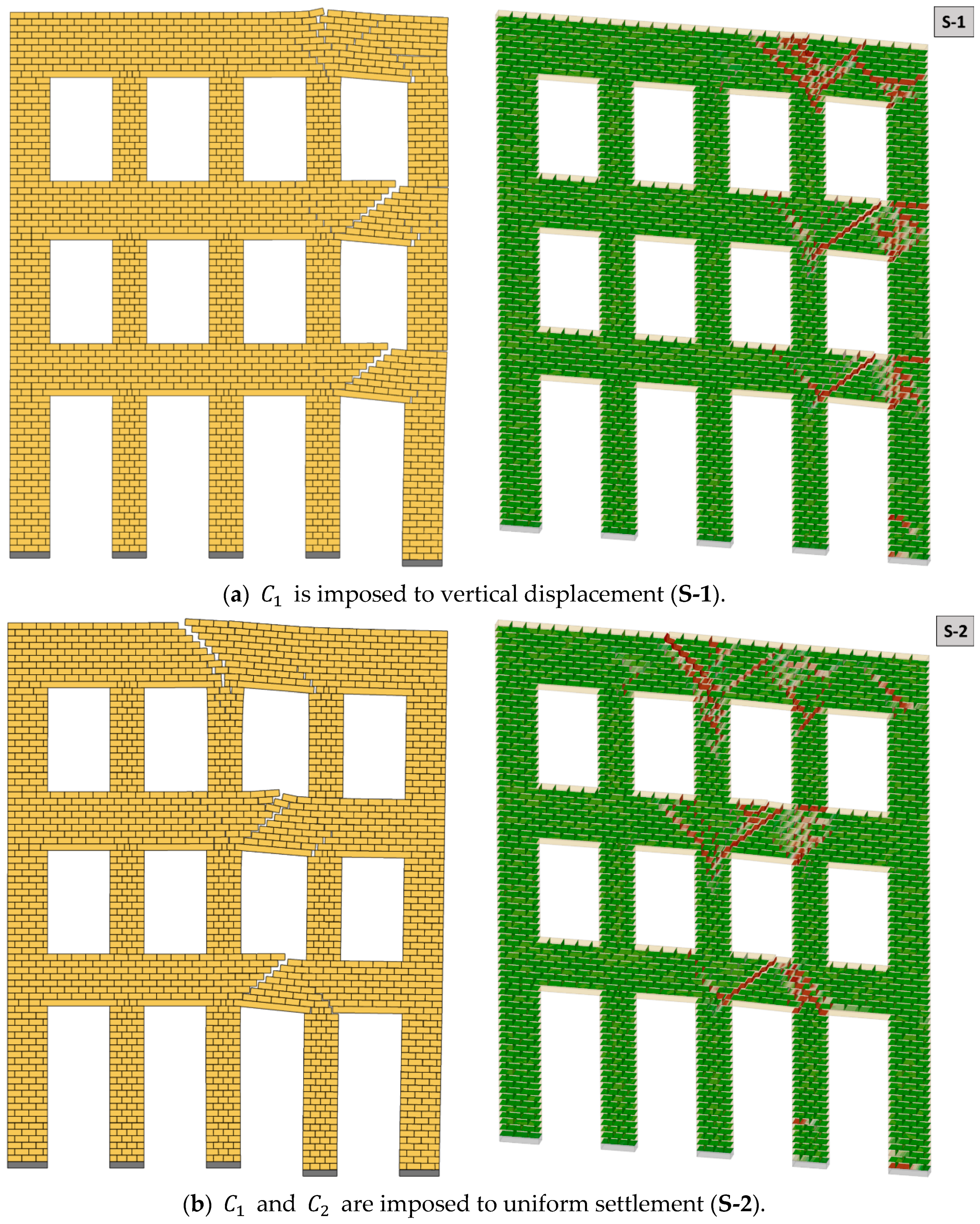
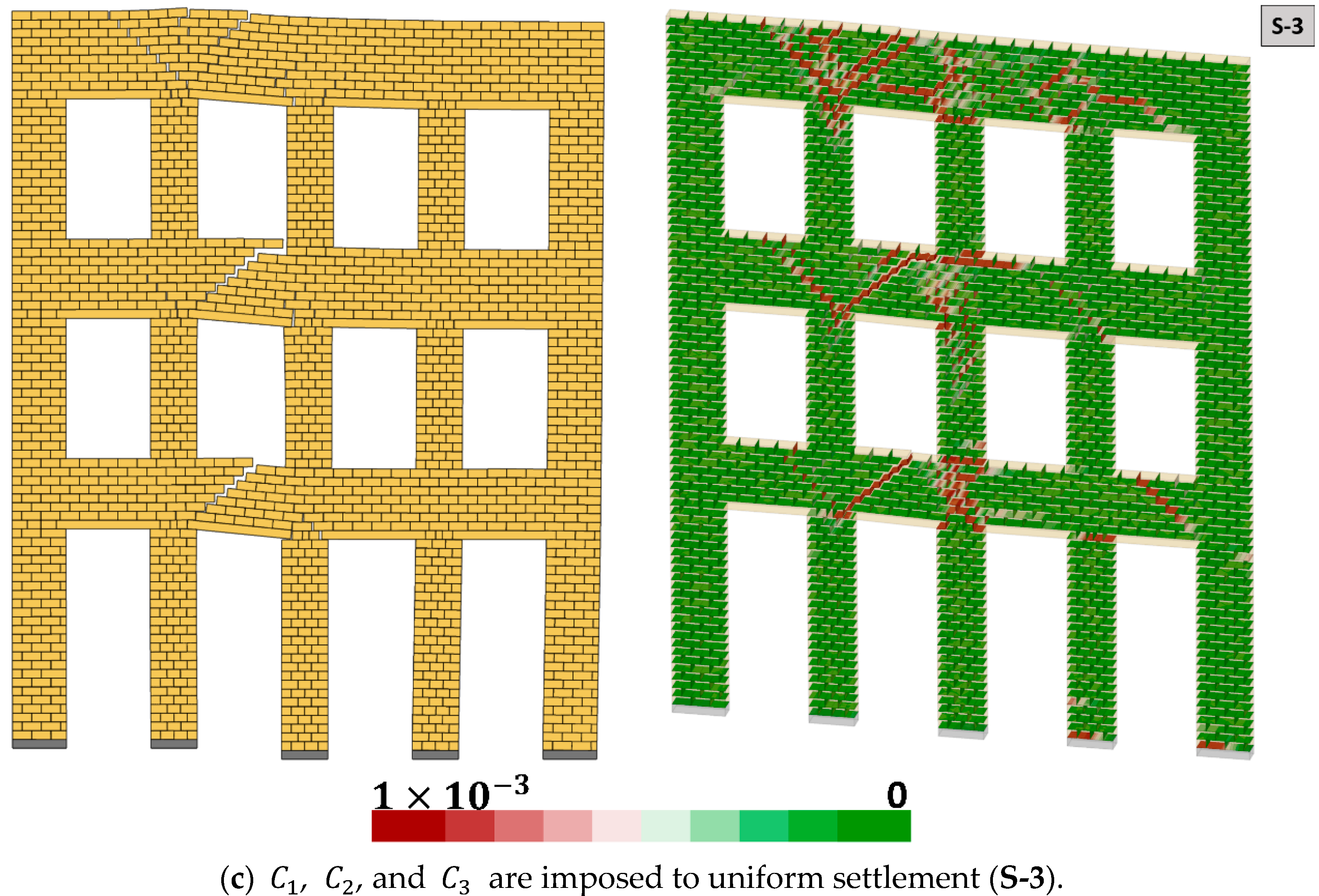
In total, six settlement-induced damage scenarios (from S-1 to S-6) are considered to better understand the corresponding damage pattern in the examined URM masonry façade. Specifically, the first three settlement profiles are defined as uniform vertical displacement, whereas, in the remaining scenarios non-uniform displacement field, along the length of the structure is considered. The maximum vertical displacement () is determined as 0.05 m, which gives the ultimate deflection ratio () of 0.00625, passing the very severe damage threshold according to the accepted damage criteria in the literature, which is discussed in detail by Serhal et al. [35]. The displacements are gradually applied by 0.005-m increments, and after each increment, it is ensured that the structure can stand under imposed settlement profile. As mentioned in the previous section, very low displacement rates (e.g., 1×10⁻³ m/s) are assigned to support blocks to avoid unnecessary structural vibrations and oscillation in the numerical solutions. Furthermore, from the computational cost point of view, each settlement analysis requires 2 h, using a computer system Intel® CoreTM i7 CPU @ 2.7 GHz processor and 16 GB memory RAM.
The results of the D-RBA reveal that the uniform settlement profiles yield distinct localized diagonal cracks developing at the spandrels, starting from the early stages of the deflection. When the ultimate displacement is reached, the lateral deformation becomes evident, and an overturning behavior is noticed at the outer column, which can be seen in Figure 7a–c. Hence, even if we have a uniform vertical settlement, in case of slender columns (as in the analyzed URM façade), an overturning mechanism may be observed that can turn into a kinematic mechanism. In the case of non-uniform settlement scenarios (Figure 8a–c), almost doubled horizontal deflection with a lateral drift ratio (ξ) of 0.5–0.6% () is obtained compared to uniform settlement for a given maximum vertical deflection. The results demonstrate a relatively different crack pattern compared to former analyses (S-1:S-3, see Figure 7a–c), and a less critical joint opening profile is noticed when the non-uniform support settlement is defined for columns, including , , , and , as shown in Figure 8c (S-6). This suggests that the internal force distribution among the column and spandrel system is shared more evenly compared to other uniform and non-uniform settlement scenarios (S-1:S-5), causing fewer joint openings in the URM façade.
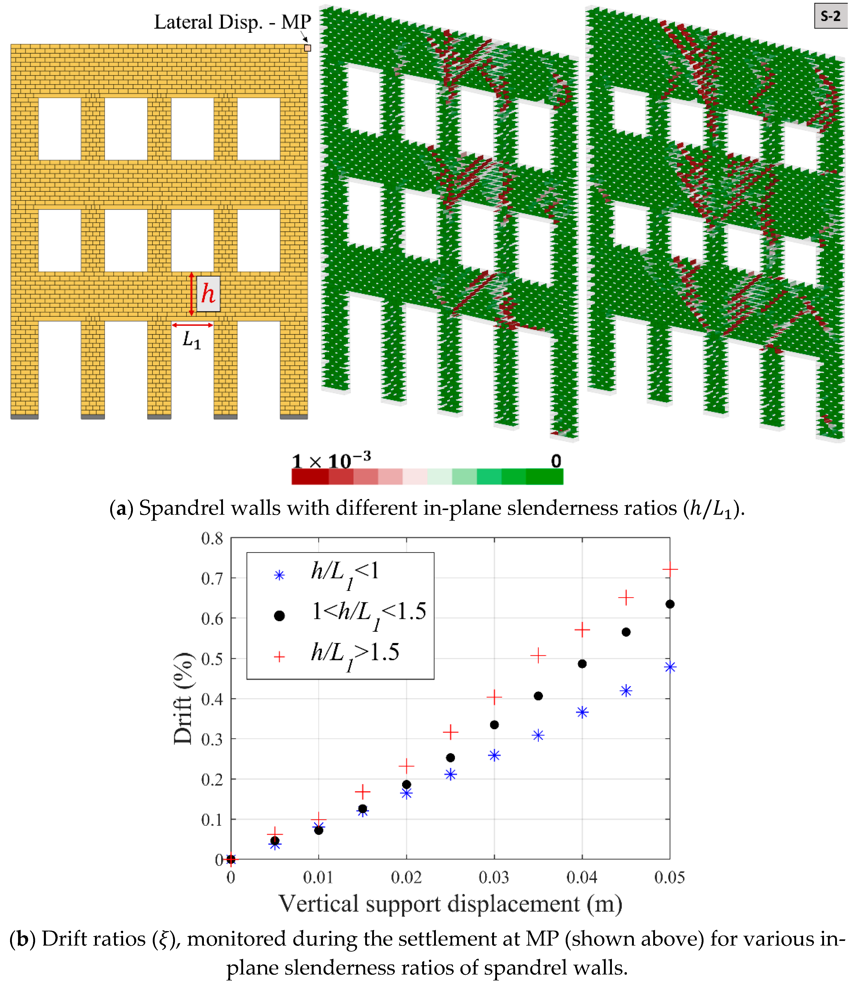
Additionally, the effect of the in-plane slenderness ratio of the spandrel wall (, see Figure 9a) is investigated to better understand its role on the cracking pattern and corresponding drift ratios. The experimental findings and computational models highlight that in-plane behavior of masonry walls subjected to lateral loading is a complex phenomenon and can be influenced by several factors, namely geometrical features (slenderness), material properties, boundary conditions, vertical loads, and morphology (or workmanship), as discussed in given references among many others [36,37,38,39,40]. However, compared to lateral loading, the settlement-induced failure mechanisms, and their relation to the macro-behavior of the URM Façades are less studied in the literature.
In this section, three slenderness ratio limits (i.e., < 1.0; 1.0 < < 1.5; > 1.5) are considered, and the second settlement scenario (S-2) is analyzed. Note that in the previous analyses, the slenderness ratio of spandrel walls (shown in Figure 7 and Figure 8) is less than 1.0 ( ≈ 0.75). Although similar cracking patterns are observed in spandrel walls with different slenderness ratios, the considerable difference is noted in terms of drift ratios, calculated based on the lateral displacement of the monitoring point (MP, demonstrated in Figure 9a). The results indicate higher drift ratios when the slenderness ratio is larger than 1.5, as shown in Figure 9b.
6. Conclusions
This research presents a validated three-dimensional discontinuum-based modeling approach, called discrete rigid block analysis (D-RBA), to predict the structural behavior of unreinforced masonry facades subjected to various scenarios of soil settlement. Note that the proposed workflow can also be adopted in two-dimensional DEM-based rigid block analysis.
The applied modeling strategy is validated based on two experimental findings, where dry and mortar joint URM masonry systems are analyzed. In both cases, good agreement is found between the computational models and experimental results in terms of structural behavior and deformation histories. Furthermore, according to the sensitivity analyses performed using the validated numerical model, the joint tensile strength is found to be the most influential input parameter, significantly influencing the deformation behavior. Finally, the modeling approach is applied to the geometric representation of a historical URM building façade. Uniform and non-uniform settlement profiles are imposed on the support blocks, and corresponding cracking mechanisms are investigated. In all settlement-induced damage patterns, severely localized spandrel cracks are noticed when the ultimate deflection ratio is reached, which may threaten structural integrity. Furthermore, the influence of spandrel walls with different in-plane slenderness ratios are explored, and the lowest drift ratios are found when less than unity for the analyzed URM façade.
Hence, it is shown that the proposed D-RBA can be a robust solution that can be utilized in the damage assessment of URM façades suffering from settlement-induced cracks. In the future study, different façade openings and stiffness ratios regarding the soil-structure interaction will be considered, which will contribute to the current knowledge base on settlement-induced damage failures for unreinforced load-bearing masonry systems.
Author Contributions
Writing—original draft preparation, methodology, R.E.; software, validation, N.T.; software, conceptualization, methodology, writing—review and editing B.P. and resources, writing—review and editing, E.E. All authors have read and agreed to the published version of the manuscript.
Funding
The financial support of the Undergraduate Creative Activities and Research Experience (UCARE) Program provided by the University of Nebraska-Lincoln is acknowledged.
Data Availability Statement
Not applicable.
Conflicts of Interest
The authors declare no conflict of interest.
References
- Boscardin, M.D.; Cording, E.J. Building response to excavation-induced settlement. J. Geotech. Eng. 1989, 115, 1–21. [Google Scholar] [CrossRef]
- Burland, J.B.; Wroth, C.P. Settlement of Buildings and Associated Damage; Pentech Press: London, UK, 1975; pp. 611–654. [Google Scholar]
- Son, M.; Cording, E.J. Responses of buildings with different structural types to excavation-induced ground settlements. J. Geotech. Geoenvir. Eng. 2011, 137, 323–333. [Google Scholar] [CrossRef]
- Camós, C.; Molins, C.; Arnau, O. Case study of damage on masonry buildings produced by tunneling induced settlements. Int. J. Archit. Herit. 2014, 8, 602–625. [Google Scholar] [CrossRef] [Green Version]
- Giardina, G.; Marini, A.; Hendriks, M.A.N.; Rots, J.G.; Rizzardini, F. Experimental analysis of a masonry façade subject to tunnelling-induced settlement. Eng. Struct. 2012, 45, 421–434. [Google Scholar] [CrossRef]
- Palmisano, F. Rapid diagnosis of crack patterns of masonry buildings subjected to landslide-induced settlements by using the load path method. Int. J. Archit. Herit. 2016, 10, 438–456. [Google Scholar] [CrossRef]
- Lemos, J.V. Discrete element modeling of masonry structures. Int. J. Archit. Herit. 2007, 1, 190–213. [Google Scholar] [CrossRef]
- Pulatsu, B.; Bretas, E.M.; Lourenço, P.B. Discrete element modeling of masonry structures: Validation and application. Earthquakes Struct. 2016, 11, 563–582. [Google Scholar] [CrossRef]
- Pulatsu, B.; Gencer, F.; Erdogmus, E. Study of the effect of construction techniques on the seismic capacity of ancient dry-joint masonry towers through DEM. Eur. J. Environ. Civ. Eng. 2020, 0, 1–18. [Google Scholar] [CrossRef]
- Pulatsu, B.; Sarhosis, V.; Bretas, E.M.; Nikitas, N.; Lourenço, P.B. Non-linear static behaviour of ancient free-standing stone columns. Proc. Inst. Civ. Eng. Struct. Build. 2017, 170, 406–418. [Google Scholar] [CrossRef]
- Saloustros, S.; Cervera, M.; Pelà, L. Tracking multi-directional intersecting cracks in numerical modelling of masonry shear walls under cyclic loading. Meccanica 2018, 53, 1757–1776. [Google Scholar] [CrossRef] [Green Version]
- Saloustros, S.; Cervera, M.; Pelà, L. Challenges, Tools and Applications of Tracking Algorithms in the Numerical Modelling of Cracks in Concrete and Masonry Structures. Arch. Comput. Methods Eng. 2019, 26, 961–1005. [Google Scholar] [CrossRef] [Green Version]
- Lourenço, P.B.; Rots, J.G. Multisurface interface model for analysis of masonry structures. J. Eng. Mech. 1997, 123, 660–668. [Google Scholar] [CrossRef]
- Gonen, S.; Pulatsu, B.; Erdogmus, E.; Karaesmen, E.; Karaesmen, E. Quasi-Static Nonlinear Seismic Assessment of a Fourth Century A.D. Roman Aqueduct in Istanbul, Turkey. Heritage 2021, 4, 401–421. [Google Scholar] [CrossRef]
- Pulatsu, B.; Erdogmus, E.; Lourenço, P.B.; Lemos, J.V.; Tuncay, K. Simulation of the in-plane structural behavior of unreinforced masonry walls and buildings using DEM. Structures 2020, 27, 2274–2287. [Google Scholar] [CrossRef]
- Gonen, S.; Pulatsu, B.; Soyoz, S.; Erdogmus, E. Stochastic discontinuum analysis of unreinforced masonry walls: Lateral capacity and performance assessments. Eng. Struct. 2021, 238, 112175. [Google Scholar] [CrossRef]
- Cundall, P.A. The Measurement and Analysis of Accelerations in Rock Slopes; University of London (Imperial College of Science and Technology): London, UK, 1971. [Google Scholar]
- Erdogmus, E.; Pulatsu, B.; Gaggioli, A.; Hoff, M. Reverse Engineering a Fully Collapsed Ancient Roman Temple through Geoarchaeology and DEM. Int. J. Archit. Herit. 2020. [Google Scholar] [CrossRef]
- Ravi Prakash, P.; Pulatsu, B.; Lourenço, P.B.; Azenha, M.; Pereira, J.M. A meso-scale discrete element method framework to simulate thermo-mechanical failure of concrete subjected to elevated temperatures. Eng. Fract. Mech. 2020, 239, 107269. [Google Scholar] [CrossRef]
- Pulatsu, B.; Gonen, S.; Erdogmus, E.; Lourenço, P.B.; Lemos, J.V.; Hazzard, J. Tensile Fracture Mechanism of Masonry Wallettes Parallel to Bed Joints: A Stochastic Discontinuum Analysis. Modelling 2020, 1, 78–93. [Google Scholar] [CrossRef]
- Malomo, D.; DeJong, M.J.; Penna, A. Distinct element modelling of the in-plane cyclic response of URM walls subjected to shear-compression. Earthq. Eng. Struct. Dyn. 2019, 48, 1322–1344. [Google Scholar] [CrossRef]
- Napolitano, R.K.; Glisic, B. Methodology for diagnosing crack patterns in masonry structures using photogrammetry and distinct element modeling. Eng. Struct. 2019, 181, 519–528. [Google Scholar] [CrossRef]
- Lemos, J.V. The basis for masonry analysis with UDEC and 3DEC. In Computational Modeling of Masonry Structures Using the Discrete Element Methods; Sarhosis, V., Bagi, K., Lemos, J.V., Milani, G., Eds.; IGI Global: Hershey, PA, USA, 2016; pp. 61–89. [Google Scholar] [CrossRef]
- ITASCA. 3DEC—Universal Discrete Element Code Manual. Theory and Background; Itasca Consulting Group Inc.: Minneapolis, MN, USA, 2004. [Google Scholar]
- 3DEC 3 Dimensional Distint Element Code User’s Guide; Itasca Consulting Group Inc.: Minneapolis, MN, USA, 2003.
- Portioli, F.; Cascini, L. Large displacement analysis of dry-jointed masonry structures subjected to settlements using rigid block modelling. Eng. Struct. 2017, 148, 485–496. [Google Scholar] [CrossRef]
- Godio, M.; Stefanou, I.; Sab, K. Effects of the dilatancy of joints and of the size of the building blocks on the mechanical behavior of masonry structures. Meccanica 2018, 53, 1629–1643. [Google Scholar] [CrossRef]
- Erdogmus, E.; Pulatsu, B.; Can, B.; Ozkan, K. Analysis of the Last Standing Arch of the Roman Aqueduct at Blaundos. In Proceedings of the 13th North American Masonry Conference; Dillion, P.B., Fonseca, F.S., Eds.; The Masonry Society: Salt Lake City, UT, USA, 2019; pp. 483–493. [Google Scholar]
- Peck, R.B. Deep excavations and tunneling in soft ground. In Proceedings of the 7th International Conference Soil Mechanics and Foundation Engineering; University Nacional Autonoma de Mexico: Mexico City, Mexico, 1969; pp. 225–290. [Google Scholar]
- Pulatsu, B.; Erdogmus, E.; Lourenço, P.B.; Quey, R. Simulation of uniaxial tensile behavior of quasi-brittle materials using softening contact models in DEM. Int. J. Fract. 2019, 217, 105–125. [Google Scholar] [CrossRef]
- Lourenço, P.B.; Rots, J.G.; Van Der Pluijm, R. Understanding the tensile behavior of masonry parallel to bed joints: A numerical approach. Mason. Int. 1999, 12, 96–103. [Google Scholar]
- Lemos, J.V.; Campos Costa, A.; Bretas, E.M. Assessment of the seismic capacity of stone masonry walls with block models. In Computational Methods in Earthquake Engineering Computational Methods in Applied Sciences; Papadrakakis, M., Lagaros, N.D., Fragiadakis, M., Eds.; Springer: Berlin/Heidelberg, Germany, 2011; Volume 2, p. 584. ISBN 9789400700529. [Google Scholar]
- Lemos, J.V.; Campos Costa, A. Simulation of Shake Table Tests on Out-of-Plane Masonry Buildings. Part (V): Discrete Element Approach. Int. J. Archit. Herit. 2017, 11, 117–124. [Google Scholar] [CrossRef]
- Landolfo, R.; Gagliardo, R.; Cascini, L.; Portioli, F.; Malena, M.; Tomaselli, G.; de Felice, G. Rigid block and finite element analysis of settlement-induced failure mechanisms in historic masonry walls. Frat. Integrita Strutt. 2020, 14, 517–533. [Google Scholar] [CrossRef] [Green Version]
- Serhal, J.; Deck, O.; Al Heib, M.; Chehade, F.H.; Youssef Abdel Massih, D. Damage of masonry structures relative to their properties: Development of ground movement fragility curves. Eng. Struct. 2016, 113, 206–219. [Google Scholar] [CrossRef] [Green Version]
- Pulatsu, B.; Gonen, S.; Erdogmus, E.; Lourenço, P.B.; Lemos, J.V.; Prakash, P.R. In-plane structural performance of dry-joint stone masonry walls: A spatial and non-spatial stochastic discontinuum analysis. Eng. Struct. 2021, 242, 112620. [Google Scholar] [CrossRef]
- Celano, T.; Umberto Argiento, L.; Ceroni, F.; Casapulla, C. Literature review of the in-plane behavior of masonry walls: Theoretical vs. experimental results. Materials 2021, 14, 3063. [Google Scholar] [CrossRef]
- Betti, M.; Galano, L.; Petracchi, M.; Vignoli, A. Diagonal Cracking Shear Strength of Unreinforced Masonry Panels: A Correction Proposal of the b Shape Factor. Bull. Earthq. Eng. 2015, 13, 3151–3186. [Google Scholar] [CrossRef]
- Calderini, C.; Cattari, S.; Lagomarsino, S. In-Plane Strength of Unreinforced Masonry Piers. Earthq. Eng. Struct. Dyn. 2009, 38, 243–267. [Google Scholar] [CrossRef]
- Lourenço, P.B.; Oliveira, D.V.; Roca, P.; Orduña, A. Dry Joint Stone Masonry Walls Subjected to In-Plane Combined Loading. J. Struct. Eng. 2005, 131, 1665–1673. [Google Scholar] [CrossRef] [Green Version]
Figure 1.
Point-contact representation and defined orthogonal spring (in 2D).

Figure 2.
The results of the validation study—1: D-RBA vs. experiment [26] and contact stiffness sensitivity analysis.
Figure 2.
The results of the validation study—1: D-RBA vs. experiment [26] and contact stiffness sensitivity analysis.

Figure 3.
Representation of proposed discrete element model and applied for support settlement.


Figure 4.
Predicted structural behavior and related displacement histories of D-RBA compared to reference study.
Figure 4.
Predicted structural behavior and related displacement histories of D-RBA compared to reference study.


Figure 5.
Sensitivity analyses considering the tensile strength and the friction angle.

Figure 6.
Historical building (left) and computational model (right); Dimensions: : 2.85, : 1.9, : 10,: 8, : 1.15—Dimensions are in meters, and columns are denoted as .
Figure 6.
Historical building (left) and computational model (right); Dimensions: : 2.85, : 1.9, : 10,: 8, : 1.15—Dimensions are in meters, and columns are denoted as .

Figure 7.
Uniform support settlement D-RBA: Crack pattern (left) and joint opening (right, in meters) when = 0.05 m.
Figure 7.
Uniform support settlement D-RBA: Crack pattern (left) and joint opening (right, in meters) when = 0.05 m.


Figure 8.
Non-uniform support settlement D-RBA: Crack pattern (left) and joint opening (right, in meters) when = 0.05 m.
Figure 8.
Non-uniform support settlement D-RBA: Crack pattern (left) and joint opening (right, in meters) when = 0.05 m.


Figure 9.
Damage response of URM Façade with different slenderness ratios of spandrel walls: Crack pattern ( = 0.05 m) and drift ratios.
Figure 9.
Damage response of URM Façade with different slenderness ratios of spandrel walls: Crack pattern ( = 0.05 m) and drift ratios.


Table 1.
Material and contact properties.
| 2000 | 10 × 109 | 4 × 10⁹ | 0.1 × 10⁶ | 35 |
Publisher’s Note: MDPI stays neutral with regard to jurisdictional claims in published maps and institutional affiliations. |
© 2021 by the authors. Licensee MDPI, Basel, Switzerland. This article is an open access article distributed under the terms and conditions of the Creative Commons Attribution (CC BY) license (https://creativecommons.org/licenses/by/4.0/).
Share and Cite
MDPI and ACS Style
Ehresman, R.; Taylor, N.; Pulatsu, B.; Erdogmus, E. Discrete Rigid Block Analysis to Assess Settlement Induced Damage in Unreinforced Masonry Façades. CivilEng 2021, 2, 541-555. https://0-doi-org.brum.beds.ac.uk/10.3390/civileng2030030
AMA Style
Ehresman R, Taylor N, Pulatsu B, Erdogmus E. Discrete Rigid Block Analysis to Assess Settlement Induced Damage in Unreinforced Masonry Façades. CivilEng. 2021; 2(3):541-555. https://0-doi-org.brum.beds.ac.uk/10.3390/civileng2030030
Chicago/Turabian StyleEhresman, Ryan, Nathan Taylor, Bora Pulatsu, and Ece Erdogmus. 2021. "Discrete Rigid Block Analysis to Assess Settlement Induced Damage in Unreinforced Masonry Façades" CivilEng 2, no. 3: 541-555. https://0-doi-org.brum.beds.ac.uk/10.3390/civileng2030030