
Fiber Reinforced Polymer as Wood Roof-to-Wall Connections to Withstand Hurricane Wind Loads

Department of Civil and Environmental Engineering, The University of Toledo, Toledo, OH 43606, USA
*
Author to whom correspondence should be addressed.
CivilEng 2021, 2(3), 652-669; https://0-doi-org.brum.beds.ac.uk/10.3390/civileng2030036
Submission received: 8 July 2021
/
Revised: 5 August 2021
/
Accepted: 6 August 2021
/
Published: 8 August 2021
(This article belongs to the Special Issue Early Career Stars in Civil Engineering)
Abstract
:Light wood roof-to-wall connections are vulnerable when subjected to high-speed winds. In lieu of traditional metal connections, the present finite element analysis (FEA) study focuses on the use of epoxy and easy-to-apply, noncorrosive FRP ties to connect the roof and the walls in wood frames. The FEA models of the wood roof-to-wall GFRP connection were validated with an experimental study in the literature. Subsequently parametric study was performed on the validated FEA models. Parameters considered were the addition of anchorages to secure the GFRP ties for FEA models of shear and uplift tests, and various FRP types. Wood roof-to-wall connection uplift model was subjected to monotonic cyclic loading to simulate the effect of wind load. In addition, carbon and basalt FRP ties were also examined under monotonic cyclic loading. To evaluate the efficiency of GFRP ties with and without anchorages, the shear and uplift design loads specified in ASCE 7-16 were calculated. Finally, a formula was proposed to approximate the shear strength of GFRP connection in comparison with double shear bolted metal plate connections. The FEA models and experimental results were in good agreement. The finite element results revealed that anchorage increased the uplift load capacity by 15% but the increase in shear capacity was insignificant. Comparing glass, carbon, and basalt FRP ties, BFRP was superior in deformation capacity and CFRP provided more stiffness on uplift test simulation. GFRP ties were found to be approximately nine times stronger in shear and two times stronger in uplift resistance than hurricane clips. Finally, the proposed formula could predict the shear strength of GFRP tie connection which in turns contributes to the design and future research.
1. Introduction
Most structures affected by high-speed winds and hurricanes are light wood framed residential structures. The damage caused by these extreme events may be due to many factors, such as deficient design, construction error, wall-diaphragm connection type, among others [1]. Wall-diaphragm connection can affect overall performance of any framed structure but there has been very limited test on their performance and efficiency [2].
Designing connections between members when it comes to wooden structures must be carefully done for continuous transfer of forces through the load path [3]. Widely used traditional types of connection, like nails, bolts, and hurricane clips, have disadvantages of weakening the wood due to penetration, water seepage through the holes, rusting, and deterioration in a short period of time. Traditional connectors like nails and bolts may be adequate for gravity load but are not necessarily capable of withstanding lateral and uplift loads. Nevertheless, many studies are still focused on conventional nails, metal plates, and clips with nails [4,5]. Riley [5] tested two types of roof-to-wall connections: toe-nails and hurricane metal clips. Hurricane clips were found to have more residual strength and uplift capacity than toe-nailed connections. Morrison [4] also rules out the use of conventional connections, like toe-nails, as they performed poorly during peak wind gusts. None of the toe-nailed connections could satisfy the 100 mph wind load criteria of the code [6]. To fully understand the behavior of wood frame buildings under strong winds and hurricanes, both component and full-scale tests are necessary [7].
According to investigation by the National Association of Home Builders (NAHB) [8] on the roof-to-wall connections in residential construction, there are several inconsistencies in the methodologies used for the engineering analysis of hardware-type connections that can lead to development of inaccurate and inadequate connection designs.
Comparative study [9] on conventional intrusive and glued or non-intrusive connections suggested that the performance of glued connections was superior to that of metal and toe-nailed connections. Fiber reinforced polymer (FRP) composites, such as carbon, glass, aramid, and basalt, are good replacements for steel material due to their non-corrosive nature while providing high tensile strength and strain [10]. Several studies have focused on the use of FRPs to strengthen the structural performance of concrete columns, beams, shear walls, and other structural members [11,12,13,14,15,16].
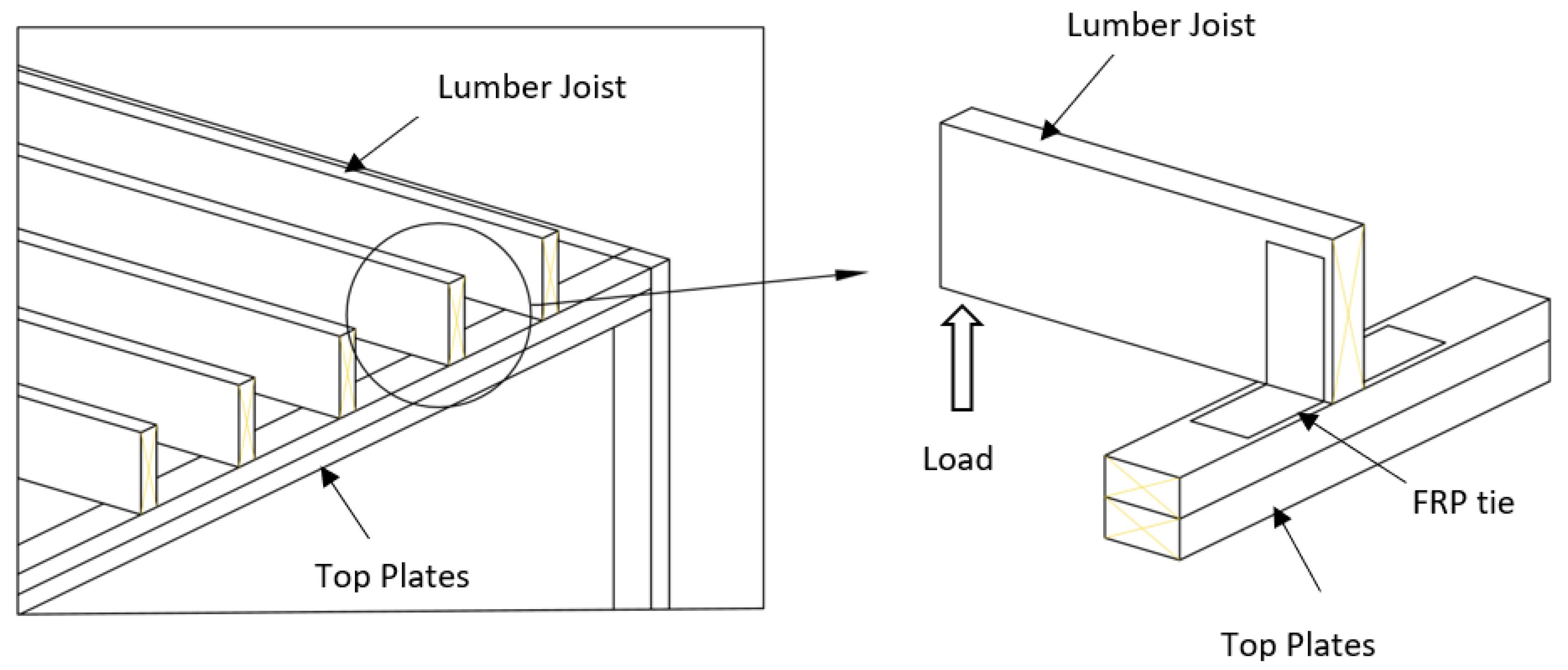
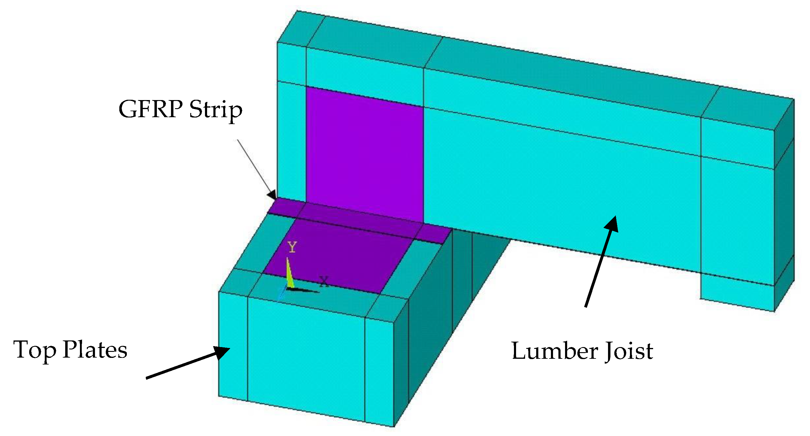
However, there are few studies on use of FRP on wood [17,18,19] and even fewer studies on the interface between FRP and wood [20,21]. Limited studies have been performed on the use of FRP in improving the performance of connections in light-weight wood framed structures subjected to wind load. An experimental study [22] was conducted on fiber-reinforced polymer as a roof-to-wall connection. FRP as roof-to-wall connections were tested at component level by performing shear and uplift tests simulating the load exerted by high-speed winds and hurricanes. The experimental results revealed that the load capacity of the FRP tie exceeded the load capacity of hurricane clips. On the other hand, Azzi et al. [23] experimentally studied the behavior of roof-to-wall connections strengthened with FRP under simulated hurricane conditions. It was found that FRP sheets were more effective than metal connectors in terms of strength. However, the lateral load resistance of FRP sheets and their metal counterparts were equivalent. The present study focuses on use of FRP as a roof-to-wall connection in wood frames shown in Figure 1.
2. Objectives
In lieu of traditional metal connections, the present numerical study focuses on the use of epoxy and easy-to-apply, noncorrosive FRP ties to connect the roof and the walls in wood frames. The FEA models of the wood roof-to-wall FRP connections were developed and validated using an experimental study in the literature [22] which was performed on component level shear and uplift tests representing high-speed wind loads effect on roof-to wall-connection. Subsequently parametric study was performed on the validated FEA models. Parameters considered were the addition of anchorages to secure the GFRP ties for FEA models of shear and uplift tests, and various FRP types. Wood roof-to-wall connection uplift model was subjected to monotonic cyclic loading to simulate the effect of wind load. In addition, carbon and basalt FRP ties were also examined under monotonic cyclic loading. To evaluate the efficiency of GFRP ties with and without anchorages, the shear and uplift design loads specified in ASCE 7-16 [24] were calculated. Finally, a formula was proposed to calculate the shear strength of GFRP connection in comparison with double shear bolted metal plate connections to aid design and future research.
3. Experimental Program Adopted for Validation of FEA Model
In a wooden framed structure, the roof-to-wall connection is one of the most critical components affected by the wind load. To perform experiments on roof-to-wall connections subjected to actual high-speed wind load is challenging. However, component level testing is a simpler alternative to determine the shear and uplift strength capacities and the efficiency of a connection. The following section summarizes the experimental program [22] adopted in this paper to validate the accuracy of the finite element analysis models of the GFRP wood connection.
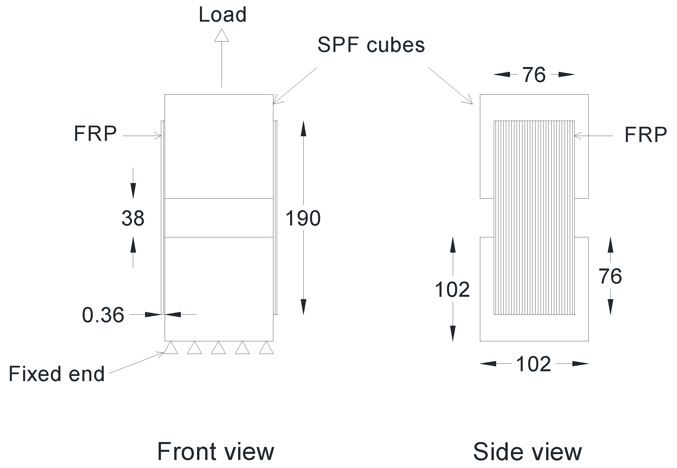
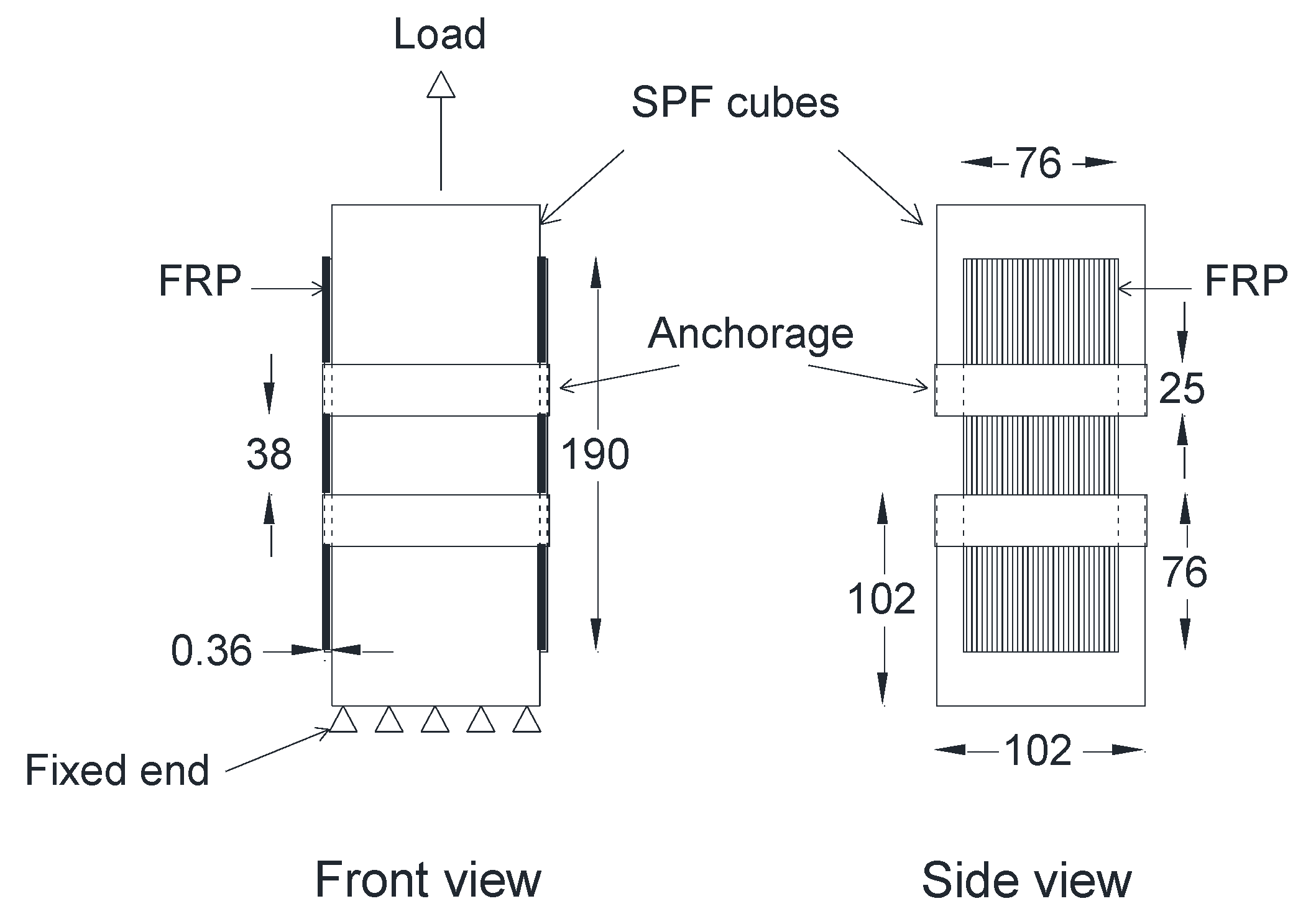
The first step in the experiment was to determine the shear bond strength at the wood–FRP interface by conducting a double lap shear test, as shown in Figure 2. Two cubes (102 × 102 × 102 mm3) of spruce–pine–fir (SPF) with a gap of 38 mm in between were connected by E-glass FRP strips applied to both sides using epoxy. One of the blocks was fixed while load was applied on the other block, as shown in Figure 2. The GFRP strip had a thickness of 0.36 mm, tensile strength, and tensile modulus of 612 MPa and 26.12 GPa, respectively. Epoxy adhesive had a tensile strength of 55 MPa and tensile modulus of 41.40 GPa.
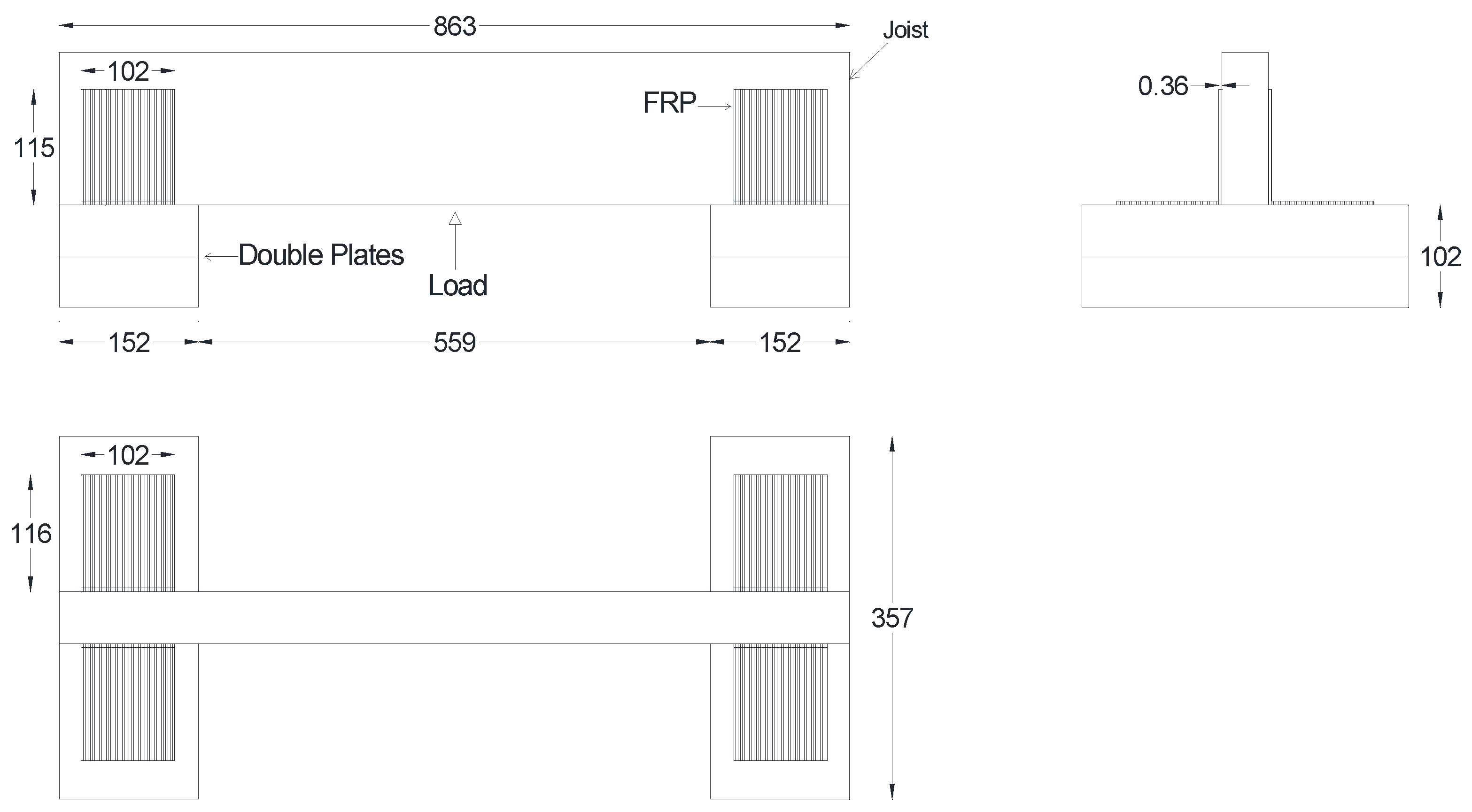
In the second step, tests on roof-to-wall connection under uplift loads were conducted to replicate the forces that a roof-to-wall connection must withstand when negative pressure is generated inside a structure during a hurricane. As this mechanism is difficult to replicate in a lab, the setup was turned upside down and the load was applied downwards to represent the uplift force. The setup consisted of lumbar joists and two base plates stacked on top of one another, as shown in Figure 3. The double plates were first placed with clear spacing of 559 mm, then the joist was placed at the center of the top plate. Thereafter, the GFRP ties were applied to connect the joist and the top plate replacing the traditional wood connection.
4. Finite Element Analysis Approach
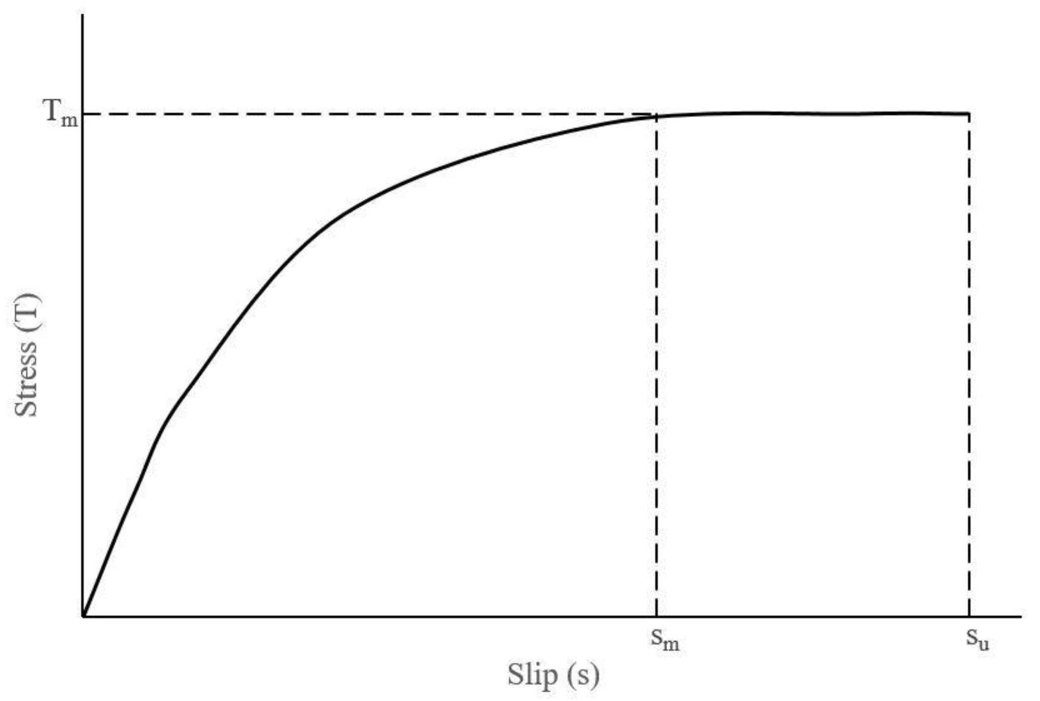
The modeling of wood material is based on linear elastic theory in three dimensions having orthotropic properties in the longitudinal, tangential, and radial directions [17,25]. To depict the behavior of timber, SOLID185 element was used. This element supports large deflection and strain and has eight nodes with three degrees of freedom at each node [26]. SOLID65 which is an eight-node solid element with a capability of capturing elastic brittle failure as well as allowing the possibility of failure in three orthogonal directions was used to model GFRP [27]. Both solid elements share the same number of degrees of freedom at each node and can simulate linear and nonlinear behaviors. Interface was simulated by contact pair TARGE170 and CONTA174 elements [28]. The zero thickness contact pair which is based on Coulomb’s friction principle and bond shear-slip model simulates the debonding and delamination of GFRP and wood interface [29]. CONTA174 (flexible material) and TARGE170 (substrate) are representing GFRP and wood, respectively. Although, some studies have assumed perfect bond between the wood and the FRP [25], in the present study both debonding and delamination were considered for more realistic modeling. Delamination occurs when the ultimate strain exceeds the plastic strain of epoxy [30]. The bond-slip data were taken from a pull-out test [20]. In Equations (1) and (2), T(s) is local bond stress, Tm is bond stress at the peak point and is equal to 5.41 MPa, s is the local slip, and sm is the value of slip at peak stress which is equal to 0.289 mm. The α parameter is 0.44. The schematic representation of the bond-slip is shown in Figure 4.
Furthermore, the value of ultimate slip (su) is formulated by using ANSYS software during cohesive zone modeling using peak slip (sm) and α parameter [28].
5. Results
In this section validation of the FEA models employed for the roof-to-wall connection is presented. Subsequently, the validated models were used to conduct parametric study entailing uniaxial cyclic load, different types of FRP materials as ties, and anchorages. Finally, the results and design considerations are discussed.
5.1. Comparison of Experiment and Finite Element Analysis Models Results
The control models of the shear (TCLS) and uplift (TCLU) tests were compared with the experimental results of their counterparts and are discussed below.
5.1.1. Component Level Double Shear Test
FEA control model of TCLS generated in the present study for validation with the double shear test performed by Canbek [22] is shown in Figure 5.
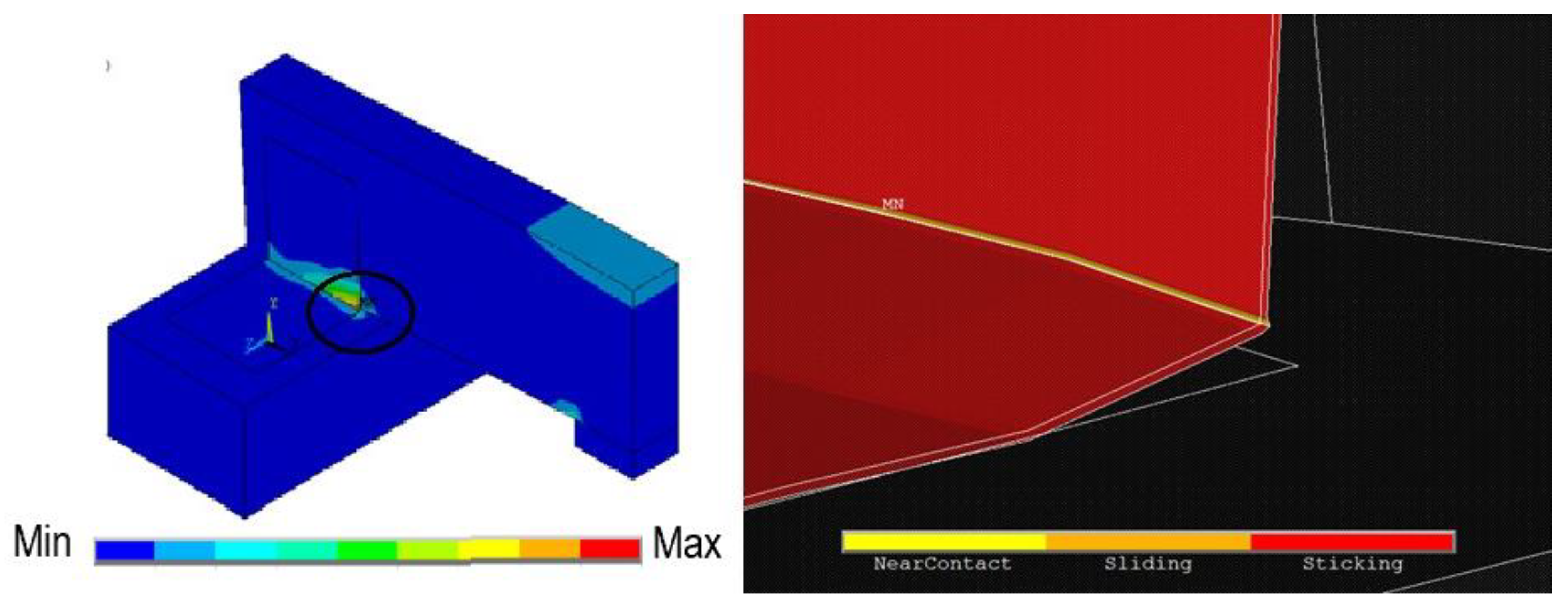
Generally, in shear tests, failure would be either debonding or rupture of the fiber. The FEA model of the double shear test failed by mode II, which was the debonding (Table 1). Slippage of the GFRP sheets occurred at the interfaces between the two wood blocks, as shown in Figure 5; similar results were observed in another experiment [31]. The failure load of finite element model was 20,868 N, as compared to experimental value of 21,540 N showing good agreement with a discrepancy of 3.12%.
5.1.2. Roof-to-Wall Connection under Uplift Test
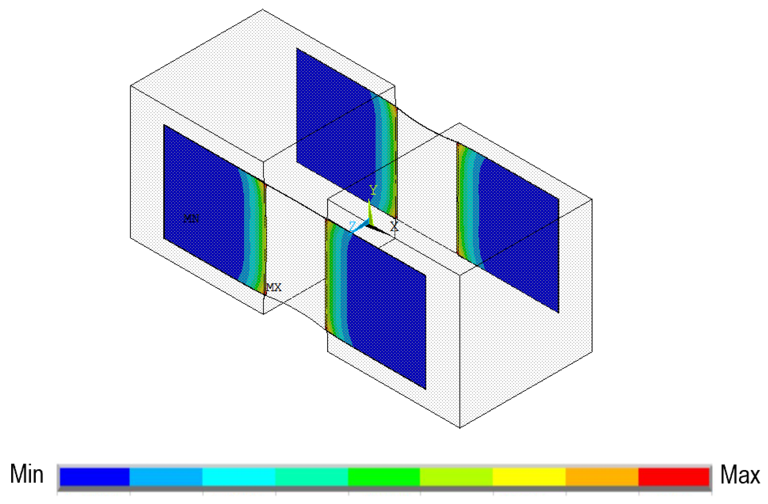
For TCLU, the L-shaped GFRP sheets were attached on both sides of lumber joists and the top plates (Figure 1). Uplift load resulted in pushing the timber lumbar joist away from the plates causing the delamination of the FRP strips from the wooden top plates. The occurrence of the failure was at the interface of the plates and the lumbar beams due to high amount of stress concentration in the corners (Figure 6). The failure of roof-to-wall connection in simulations was consistent with the experiment [22] which was Mode I: delamination failure. Similar observation was made in another study on the failure mechanism of adhesives used with FRP [32].
5.2. Parametric Study
Once the accuracy of the finite element analysis models was verified with the uplift and shear tests by Canbek [22]; the validated finite element models were used for further parametric study (Table 2).
5.2.1. Behavior of Control Model under Cyclic Uniaxial Tensile Load
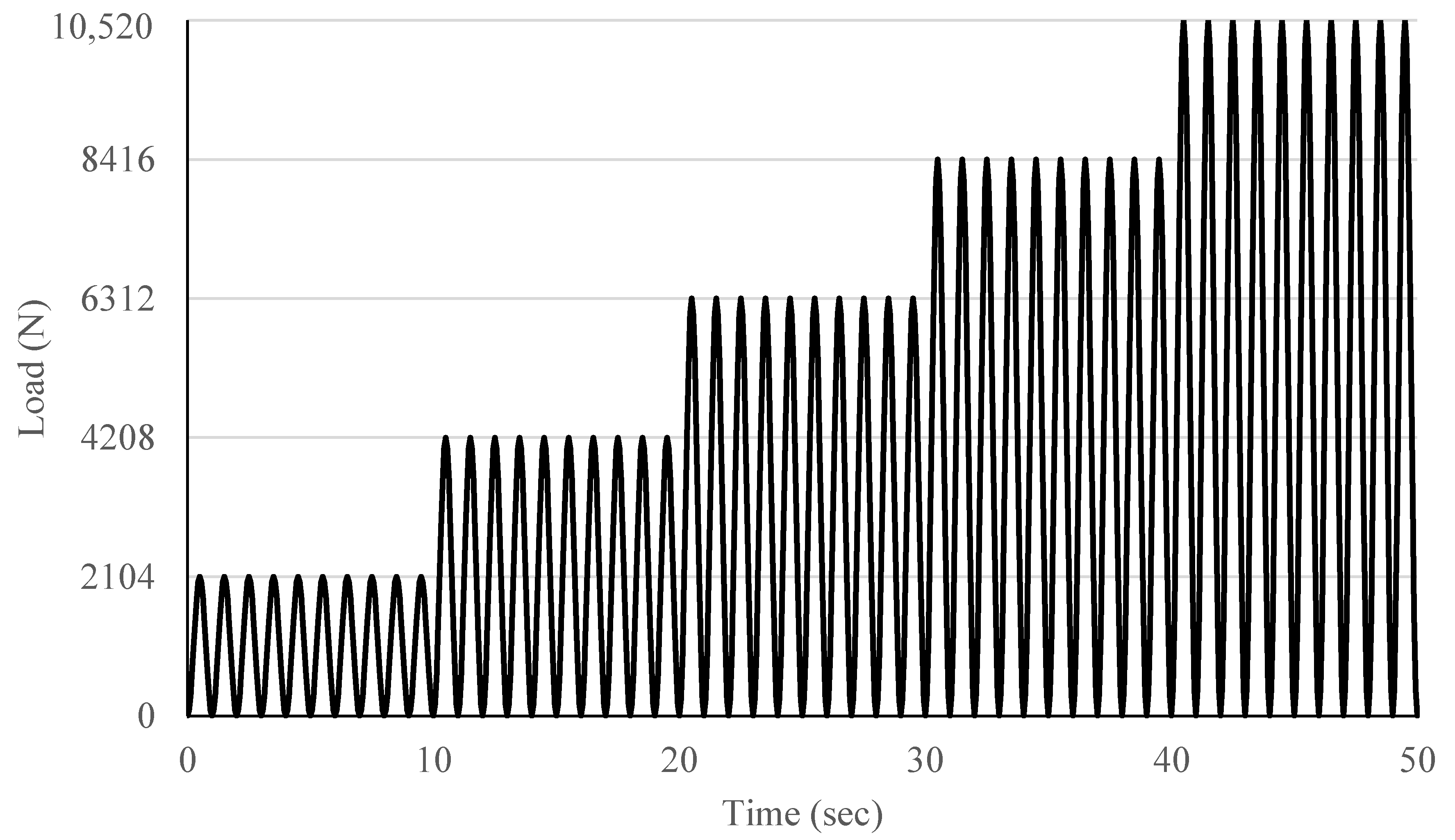
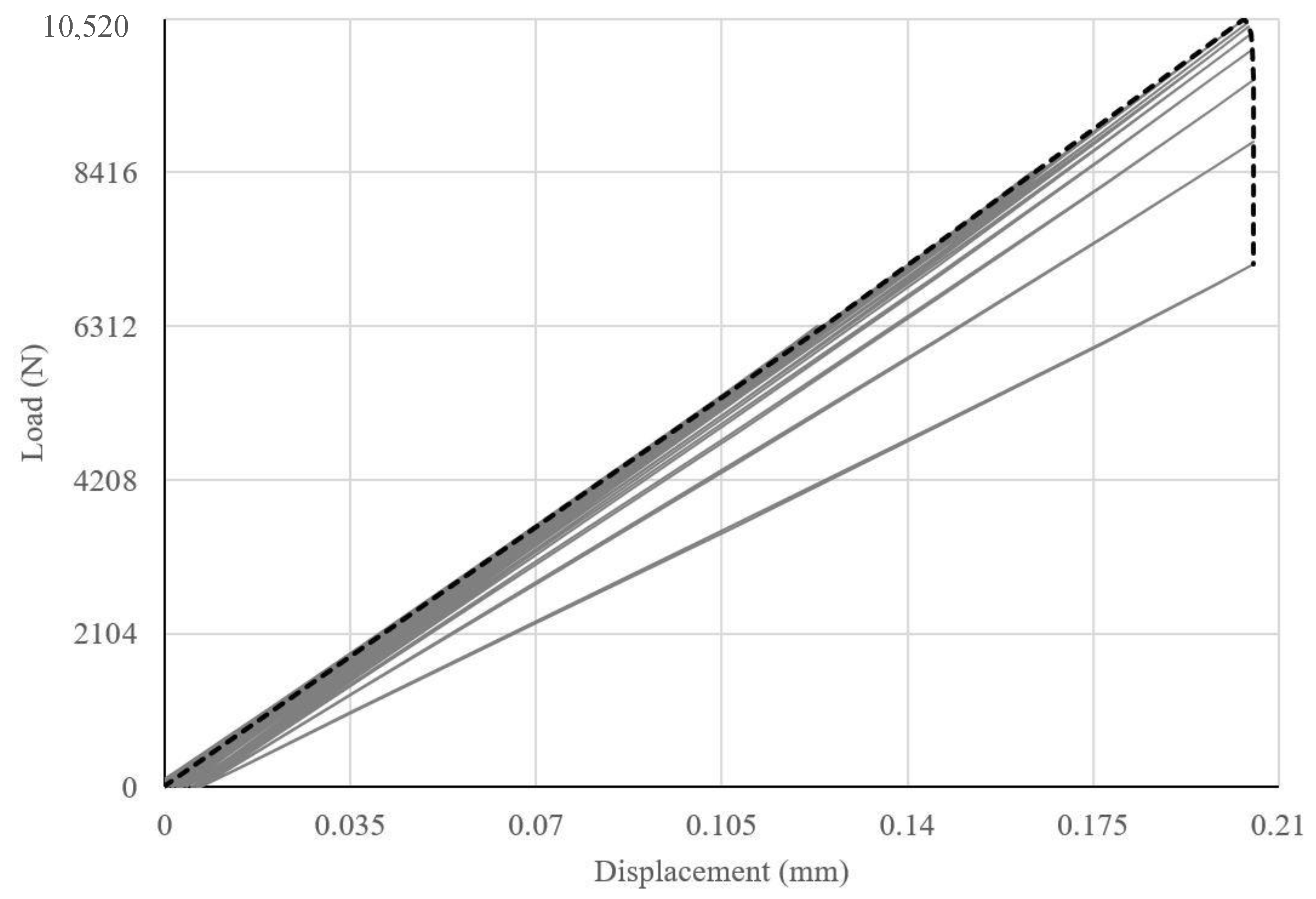
The finite element model of roof-to-wall connection under uplift load, TCLU, was subjected to cyclic loading. For the shear test model (TCLS), cyclic load was not considered as in a standard test, the application of cyclic load would be impractical. Figure 7 shows the applied uniaxial cyclic load. Similarly, a cyclic load [33] was applied to the validated FEA TCLU roof–to–wall connection model in the vertical direction. A fraction of failure load obtained from TCLU model subjected to static load was applied for few cycles and then gradually increased for the same number of cycles until it reached the failure load.
Critical nodes on GFRP tie with maximum displacement were selected in order to plot load versus displacement curve. The observed compression on the FRP ties was trivial.
The FEA model of TCLU-CYC has a typical cyclic load applied on the wooden joist in the direction shown in Figure 1. The magnitude of the load is calculated in Equation (3).
The TCLU model of roof-to-wall connection subjected to static load failed at 10,520 N. For the cyclic load, the assumption was made that the TCLU-CYC would fail on or before the maximum load failure of 10,520 N. Thus, the amplitudes were selected to be fractions of 10,520 N. The load was applied for 10 cycles with each amplitude equivalent to 20%, 40%, 60%, 80%, and 100% of 10,520 N as shown in Figure 7. When failure was not achieved after applying 100%, the amplitude was increased for another 10 cycles until failure.
In TCLU-CYC, failure was observed when the analysis stopped converging around 100% of the load. The load versus displacement of that section is shown in Figure 8. A study by Ceroni [34] to examine the shear strength of RC beam strengthened by FRP under cyclic load also reported similar results. From the slope of the load versus displacement curve, the stiffness of the FRP ties was found to be approximately 37.85 KN/mm. The energy-absorption capacity of the GFRP ties was assessed through the calculation of modulus of resilience which is equivalent to the area under the curve and was approximately 526.48 MPa.
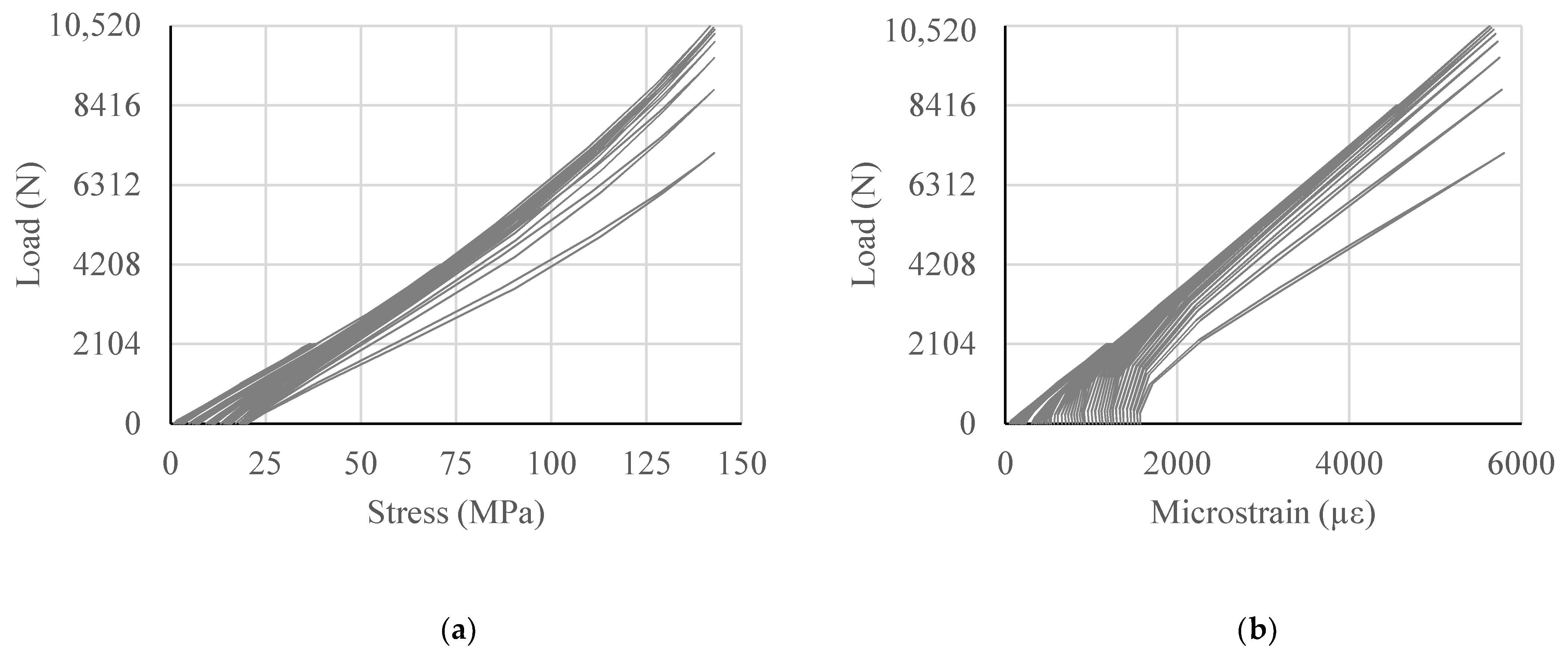
Figure 9a shows the load versus stress curve of GFRP tie under the cyclic load. The TCLU-CYC model depicts the effectiveness of the GFRP tie, since the deformation for each cycle during loading and unloading did not change drastically. It was observed that stress level upon loading and unloading was not the same for the same load. This is due to residual stress in the fiber. Likewise, Figure 9b illustrates the load versus strain curve of GFRP tie in the model TCLU-CYC. Since GFRP has linear elastic property, load versus stress or load versus strain are similar in nature.
5.2.2. Effect of Various FRP Types on Roof-to-Wall Connection under Uniaxial Cyclic Load
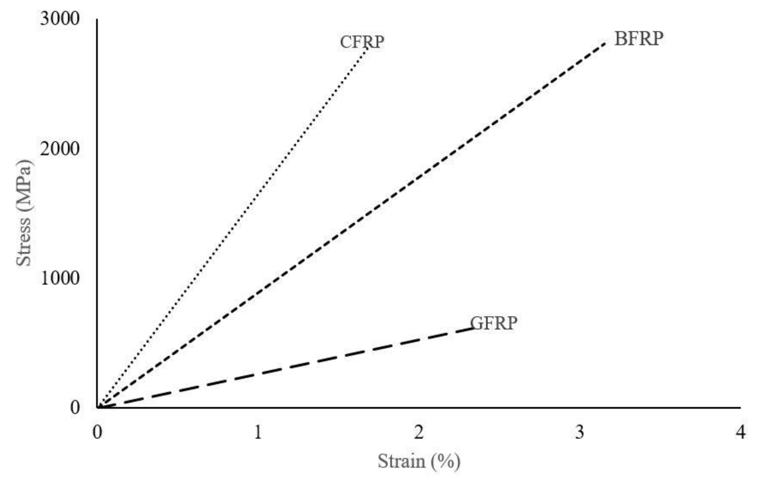
Beside GFRP, performance of other types of FRP ties such as carbon fiber reinforced polymer (CFRP); and basalt fiber reinforced polymer (BFRP) when subjected to monotonic cyclic load (Figure 7) were also investigated. Mechanical properties of various FRP types are shown in Table 3.
For comparison, the stress versus strain curves of the fibers presented in Table 3 are also shown in Figure 10.
The properties of the GFRP SikaWrap® Hex-100 G and CFRP Sika CarboDur S512 used in the FEA models were obtained from the manufacturer product data sheet [35]. GFRP has higher tolerance for elongation than CFRP; however, CFRP has the capability of higher resistance to load. The third fiber used in the present study was BFRP with comparable strength and higher rupture strain compared to the CFRP. The properties of basalt fiber reinforced polymer (BFRP) were obtained from [36].
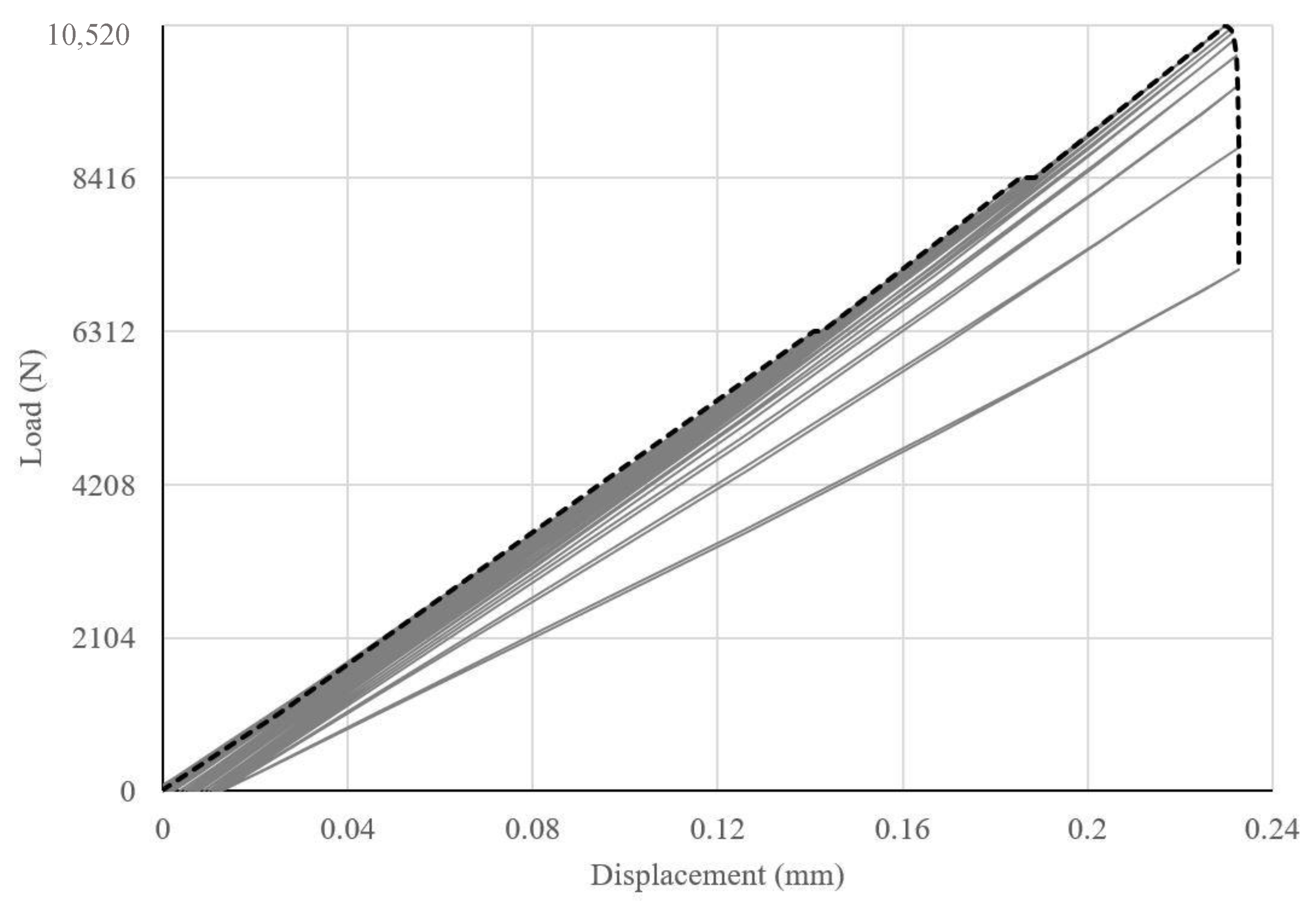
Figure 11 shows load versus displacement curve for CFRP ties with the stiffness and the modulus of resilience equal to 51.32 KN/mm and 359.85 MPa, respectively.
Similarly, the stiffness and modulus of resilience of BFRP tie in the system was found to be 45.20 KN/mm and 424.85 MPa, respectively (Figure 12).
BFRP and CFRP ties showed similar tensile strength. However, CFRP provided more stiffness to the system. In the design, if more energy absorption is desired, GFRP would be a better choice, however, BFRP could provide higher deformation capability.
5.2.3. Effect of Anchorage on the GFRP Ties in Double Shear Test Model
Various FRP anchorages include anchor spikes, transverse wrapping, FRP strips, plate anchors, bolted angles, and longitudinal chase [37]. Most studies on anchorages focused on FRP strengthened concrete members [38,39]. To the best of authors’ knowledge, no study has been performed on applying anchorage for FRP ties as wood connections.
In TCLS-A, anchorages were provided to the double shear model of roof-to-wall connection of TCLS. Figure 13 shows GFRP anchorages with a width of 25 mm wrapped around the wood blocks to anchor the GFRP ties. Due to the anchorage, the failure mode changed from the debonding observed in TCLS model to the rupture of GFRP tie in TCLS-A model. However, there was no increase in the shear capacity in TCLS-A as compared to TCLS (Table 4).
In TCLS model, the system was able to carry the load until the slip occurred followed by debonding; but, in TCLS-A, anchorages were able to stop the slippage, resulting in all the loads being transferred to the GFRP ties directly. These changes in the stress distribution are also shown in Figure 14. Consequently, the load-carrying capacity of the system did not increase but the failure mode changed from debonding to rupture of the GFRP ties.
5.2.4. Effect of Anchorage on the GFRP Ties under Uplift Force
Next, the effect of anchorage is discussed on the roof-to-wall connection under uplift load. Although, FRP wrapping provides clamping effect, FRP strip is another kind of anchorage used for structural member strengthening, which can be glued over the pre-installed fibers in the perpendicular orientation. FRP strips have been used to provide anchorage in FRP strengthened reinforced concrete beams under cyclic load [34]. In the present study, the GFRP strips were added to TCLU model at the intersection of top plates and joist to generate an anchored model of roof-to-wall connection, TCLU-A, under uplift load as shown in Figure 15.
As mentioned before, the TCLU model failed by delamination of GFRP ties from the top plate. Anchorages in the form of GFRP strips were provided on both sides of the lumber joist by applying 25 mm wide GFRP strips on top of FRP sheets at the interface with high stress concentration. The failure now shifted to debonding failure of GFRP ties from the lumber joist. Strengthening TCLU using anchorage resulted in increase of load carrying capacity from 9855.52 N to 11,387.68 N which is an increase of 15.55% as presented in Table 5.
5.3. Design Considerations
In this section, two methods are used to analyze the design of the GFRP tie. In the first method, the effectiveness of GFRP ties was evaluated by comparing shear and uplift strengths to that of ASCE 7-16 [24] requirement and to that of traditional steel hurricane clips obtained from an existing experimental study performed by Canbek [7]. In the second method, the regression analysis was performed and an equation to calculate the shear strength of the GFRP tie as a roof-to-wall connection was developed.
5.3.1. Comparison of Shear and Uplift Forces to ASCE Standards and Traditional Hurricane Clips
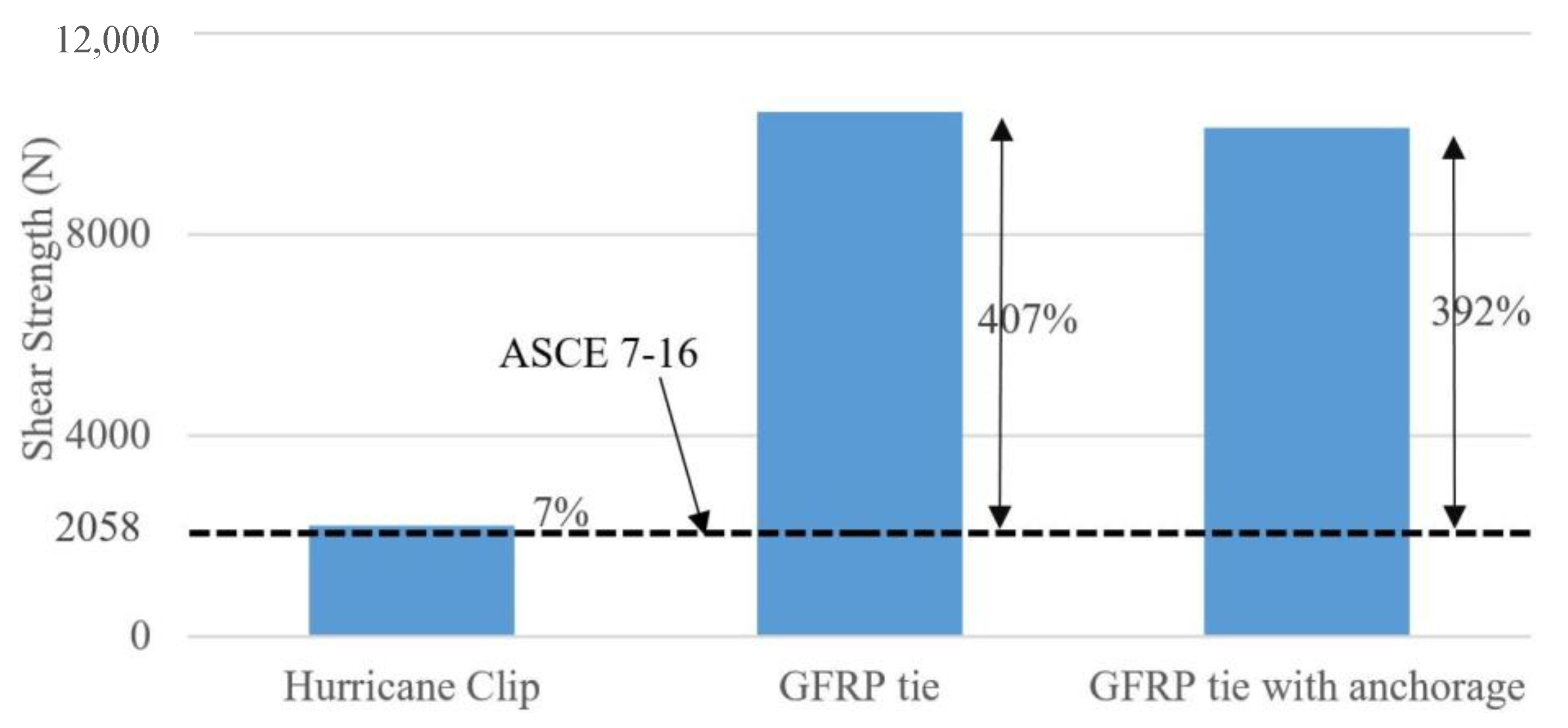
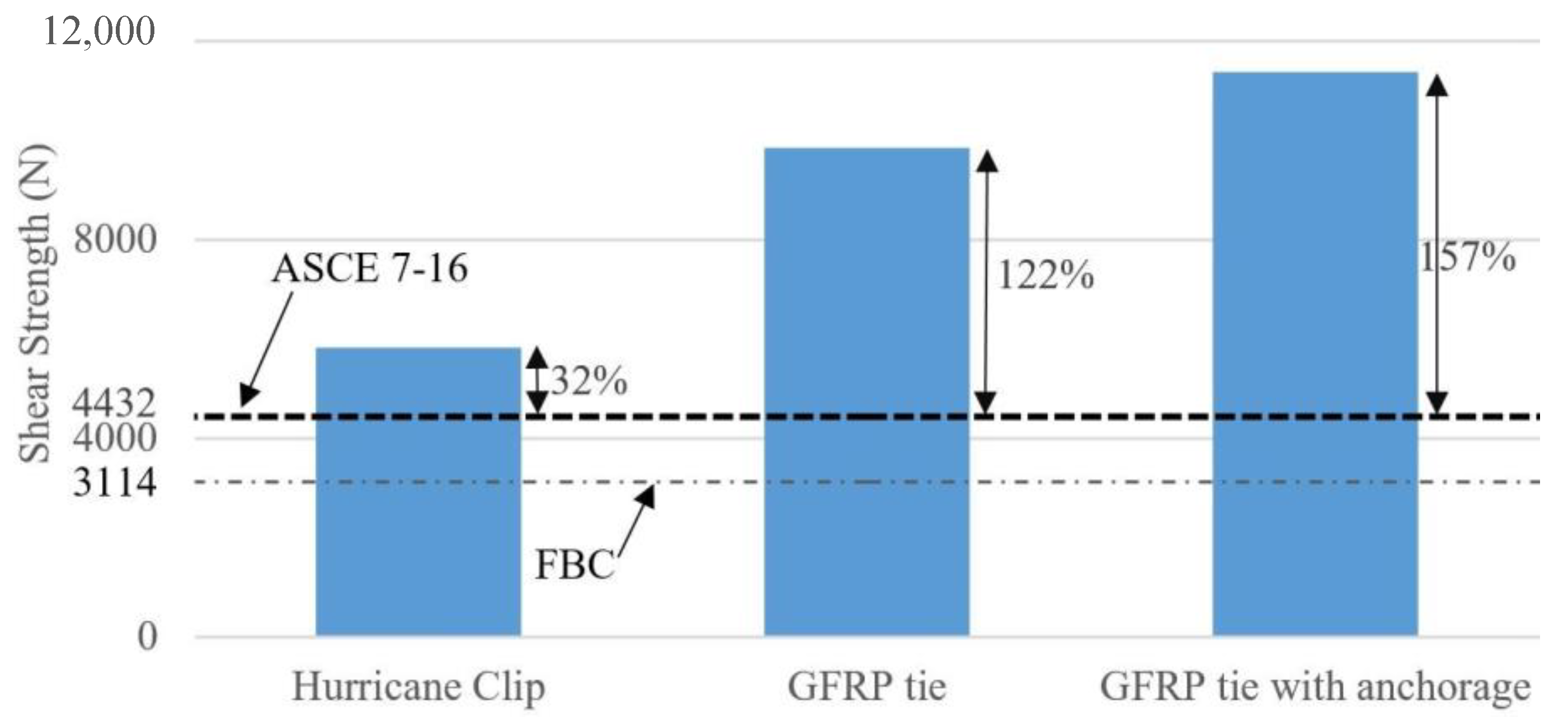
Current roof-to-wall connections, such as toe nails, hurricane straps, and hurricane clips, have not proved to be very efficient under combined loading of shear and uplift forces [40]. One way to overcome this problem is by using GFRP tie as a roof-to-wall connection. According to Florida Building Commission (International Code Council [41]), Section 2321.7(2), wood-to-wood straps must be able to resist a minimum of 3114 N of uplift load. Additionally, according to ASCE Standard 7-16, the connection should be able to withstand the shear and uplift loads calculated by the Main Wind Force Resisting System (MWFRS) method.
The most critical scenarios were selected from ASCE 7-16 [24]. In one scenario, a 700-year wind of 315 kmph and three-second gust was assumed to hit a building with a mean roof height of 10 m in an open terrain with scattered obstruction (Exposure C). A typical 11 m long roof span with 0.6 m overhang and slope of 20 degrees was selected since this roof slope experiences the worst uplift force. A minimum of 48.8 kg/m2, including self-weight, was applied to the roof to resist the uplift force. According to ASCE 7-16, the calculated shear and uplift force values were 2058 N and 4432 N, respectively.
Furthermore, the shear and uplift load capacities of traditional and mostly used steel hurricane clips were obtained from the experimental study by Canbek [7]. The average uplift and in-plane shear strengths were 5832 N and 2202 N, respectively. The shear and uplift loads of steel hurricane clips and GFRP ties are compared to the calculated values from ASCE 7-16 as shown in Table 6.
As demonstrated in Figure 16, while hurricane clip can provide sufficient shear strength for a typical residential house subjected to wind speed of 315 kmph (195 mph), it would not be able to withstand higher wind speeds. In contrast, the GFRP tie could withstand five times higher shear force than the hurricane clips. Likewise, in terms of uplift force (Figure 17), the GFRP tie outperformed hurricane clips by a factor of 1.75.
5.3.2. Analytical Model
In this section, an analytical model is presented for the calculation of shear strength of the GFRP tie with different bonded areas.
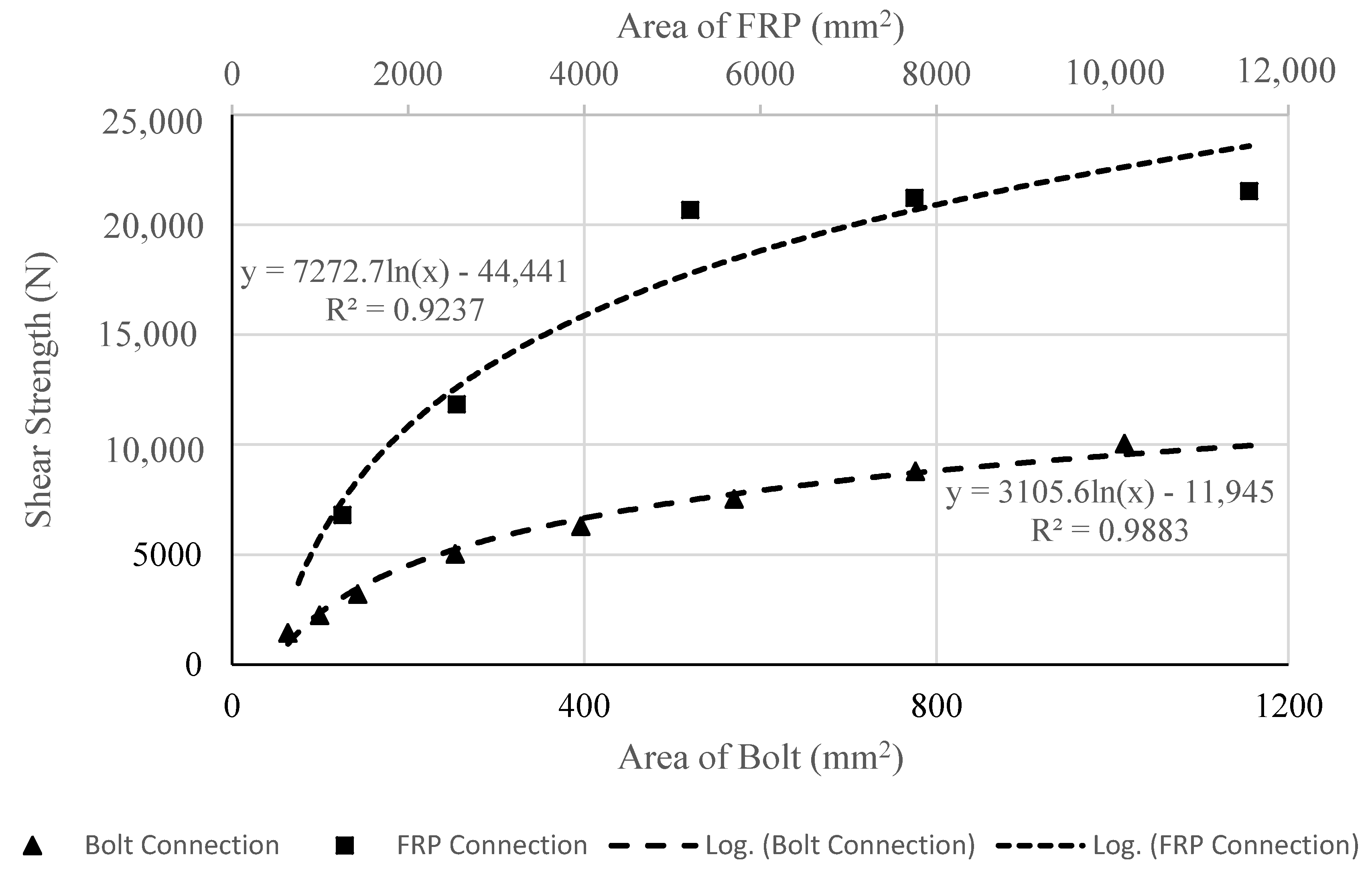
An analytical model is proposed based on shear strength results versus various bonded GFRP areas (A through E) from the direct shear test performed by Canbek [22]. Table 7 shows shear strength of the various GFRP bonded areas, including TCLS validated finite element analysis model (A’) in the present study.
Figure 18 represents comparison of regression models for GFRP tie and bolted connection since they are both double lap shear tests.
For the GFRP tie, a logarithmic trendline was the best fit curve for the data of bonded GFRP area versus shear strength (Table 7) shown in Figure 18. This regression analysis yielded the following Equation (4).
where, ZFRP is the shear strength of connection in Newton (N). AFRP is the area of the fiber reinforced polymer sheets bonded to the wood in millimeter squared (mm2). The analytical model presented in Equation (4) fits the data of bonded GFRP area versus shear strength with an R2 value of 0.9237 indicating a reliable fit since it is close to unity.
ZFRP = 7272.70 ln (AFRP) − 44,441
The shear strength of bolted connections with various bolt diameters was calculated according to NDS for Wood Construction [42].
The schematic for the bolt connection is shown in Figure 19, where ts is the thickness of metal plate (side member), tm is the thickness of the wood (main member), and D is the diameter of the bolt.
Side metal plate had a thickness of 16 gauge (1.26 mm). Shear strength of double-shear bolt in wood-to-metal connection was calculated for various diameters of the bolt ranging from 6.25 mm (1/4 in) to 25 mm (1 in). The plot of bolts with various areas and their corresponding shear strengths are also shown in Figure 18.
Likewise, a regression analysis was performed for the bolted connection with a value of R2 equal to 0.9883 indicating its accuracy. As a result, the following equation is proposed.
In Equation (5), Zbolt is the shear strength of bolted connection in Newton (N). Abolt is the area of bolt in millimeter squared (mm2).
Comparing the curves of shear strength versus area of GFRP tie and bolted connections (Figure 18), Equation (6) is proposed which is applicable when AFRP/Abolt is equal to 10.
where,
Equation (7) was derived by trial and error. To validate the accuracy of the proposed Equations (6) and (7) further, 16 gauge (1.26 mm thickness) metal side members were replaced with 14 gauge (1.63 mm thickness) side members. The 14 gauge (1.63 mm thickness) metal side members generated a factor of 1.944 and 1.927 from regression analysis and Equation (7), respectively, as shown in Table 8. This proves that the shear strength (ZFRP) of a specific GFRP bonded area can directly be calculated from Equations (6) and (7) without performing any experiment or regression analysis.
6. Summary and Conclusions
In the present paper, the finite element analysis and experimental results of an existing study on wood roof-to-wall GFRP tie connections were compared to validate the accuracy of FEA models subjected to static shear and uplift loads representing the effect of hurricane. Typical connections such as hurricane clips and steel bolts were replaced with GFRP ties to investigate their performance when subjected to hurricane loads. The roof-to-wall connection with various types of FRP ties (GFRP, CFRP, and BFRP) were also subjected to monotonic cyclic load for the uplift. Subsequently, anchorages were provided to secure the GFRP ties at the roof-to-wall connection interfaces. A regression analysis was performed for GFRP ties and bolted connection using design guidelines from NDS for wood construction. A formula for shear strength of GFRP tie was proposed after comparison of regression analyses of GFRP tie and the bolted connection. The following conclusion are drawn from this study.
- The results of TCLS and TCLU finite element control models of GFRP roof-to-wall connections and experimental study were in good agreement with less than 3% discrepancy and similar failure modes were observed under static loading condition.
- From load versus displacement data of the roof-to-wall connection under cyclic uplift load (TCLU-CYC FE model) for various FRP types, stiffness and modulus of resilience of the system were calculated. BFRP and CFRP ties showed similar tensile strength. However, CFRP provided more stiffness to the system. In the design, if more energy absorption is desired, GFRP would be a better choice. However, BFRP could provide higher deformation capability.
- Although, the provided anchorages in the double shear model (TCLS-A) changed the model of failure from debonding to the rupture of the GFRP ties, the shear load capacity did not change.
- However, the anchorages provided in the uplift model (TCLU-A) exhibited substantial increase of 15.6% in its load carrying capacity. The mode of failure changed from peeling to debonding.
- The shear and uplift design strengths for the connection was calculated using ASCE design provisions and compared with the hurricane clips and GFRP ties. Shear strength of GFRP ties was 9.5 times the strength of hurricane clip; and GFRP ties withstood 1.7 times more uplift force than a typical hurricane clip. Thus, GFRP ties are much safer connections than typical hurricane clips.
- From the regression models of the GFRP tie and the bolted wood-to-metal connection, the relation between the bonded area of GFRP tie to the area of the bolt in bolted connection was established. Subsequently, shear strength of the GFRP tie connection, with an area equal to 10 times the bolt area, is equivalent to π/ts times the shear strength of the bolted connection calculated using NDS for wood construction.
Author Contributions
Conceptualization, A.P.; methodology, A.P.; software, A.D.; validation, A.D.; formal analysis, A.D.; investigation, A.D.; writing—original draft preparation, A.D.; review, A.P. and A.D.; supervision, A.P. All authors have read and agreed to the published version of the manuscript.
Funding
This research received no external funding.
Data Availability Statement
Not applicable.
Acknowledgments
The authors thank Bibek Regmi Bagale, MS Civil Engineering, University of Toledo, for his assistance with finite element modeling methodology.
Conflicts of Interest
The authors declare no conflict of interest.
References
- Ellingwood, B.R.; Rosowsky, D.V.; Li, Y.; Kim, J.H. Fragility assessment of light-frame wood construction subjected to wind and earthquake hazards. J. Struct. Eng. 2004, 130, 1921–1930. [Google Scholar] [CrossRef]
- Lin, T.J.; LaFave, J.M. Experimental structural behavior of wall-diaphragm connections for older masonry buildings. Constr. Build. Mater. 2012, 26, 180–189. [Google Scholar] [CrossRef]
- Van De Lindt, J.W.; Graettinger, A.; Gupta, R.; Skaggs, T.; Pryor, S.; Fridley, K.J. Performance of wood-frame structures during hurricane Katrina. J. Perform. Constr. Facil. 2007, 21, 108–116. [Google Scholar] [CrossRef]
- Morrison, M.J.; Henderson, D.J.; Kopp, G.A. The response of a wood-frame, gable roof to fluctuating wind loads. Eng. Struct. 2012, 41, 498–509. [Google Scholar] [CrossRef]
- Riley, M.A.; Sadek, F. Experimental Testing of Roof to Wall Connections in Wood Frame Houses; National Institute of Standards and Technology: Gaithersburg, MD, USA, 2003.
- Cheng, J. Testing and analysis of the toe-nailed connection in the residential roof-to-wall system. For. Prod. J. 2004, 54, 58–65. [Google Scholar]
- Canbek, C. Development of a Hurricane-Resistant Roof-To-Wall Connection Using High-Performance Fiber Composites; Florida International University: Miami, FL, USA, 2009. [Google Scholar]
- National Association of Home Builders (NAHB). Roof Framing Connections in Conventional Residential Construction; Rep No. H-21172CA; National Association of Home Builders (NAHB): Washington, DC, USA, 2002; pp. 1–48. [Google Scholar]
- Reed, T.D.; Rosowsky, D.V.; Schiff, S.D. Uplift capacity of light-frame rafter to top plate connections. J. Archit. Eng. 1997, 3, 156–163. [Google Scholar] [CrossRef]
- Ku, H.; Wang, H.; Pattarachaiyakoop, N.; Trada, M. A review on the tensile properties of natural fiber reinforced polymer composites. Compos. Part B: Eng. 2011, 10, 213–222. [Google Scholar] [CrossRef] [Green Version]
- ACI (American Concrete Institute). Guide for the Design and Construction of Structural Concrete Reinforced with FRP Bars; ACI 440.1R-06; ACI: Farmington Hills, MI, USA, 2006. [Google Scholar]
- Korany, Y.; Drysdale, R. Rehabilitation of masonry walls using unobtrusive FRP techniques for enhanced out-of-plane seismic resistance. J. Compos. Constr. 2006, 10, 213–222. [Google Scholar] [CrossRef]
- Nanni, A. North american design guidelines for concrete reinforcement and strengthening using FRP: Principles, applications and unresolved issues. Constr. Build. Mater. 2003, 17, 439–446. [Google Scholar] [CrossRef]
- Parvin, A.; Altay, S.; Yalcin, C.; Kaya, O. CFRP rehabilitation of concrete frame joints with inadequate shear and anchorage details. J. Compos. Constr. 2010, 14, 72–82. [Google Scholar] [CrossRef]
- Parvin, A.; Jamwal, A.S. Performance of externally FRP reinforced columns for changes in angle and thickness of the wrap and concrete strength. Compos. Struct. 2006, 73, 451–457. [Google Scholar] [CrossRef]
- Parvin, A.; Shah, T.S. Fiber reinforced polymer strengthening of structures by near-surface mounting method. Polymers 2016, 8, 298. [Google Scholar] [CrossRef] [Green Version]
- Kim, Y.J.; Hossain, M.; Harries, K.A. CFRP strengthening of timber beams recovered from a 32 year old quonset: Element and system level tests. Eng. Struct. 2013, 57, 213–221. [Google Scholar] [CrossRef]
- Wang, B.; Bachtiar, E.V.; Yan, L.; Kasal, B.; Fiore, V. Strengthened wood beams: An experimental study. Polymers 2019, 11, 9–12. [Google Scholar] [CrossRef]
- Yang, J.-Q.; Smith, T.; Wu, Y.-F.; Feng, P. Strengthening single-bolt timber joints with externally bonded CFRP composites. In Structures; Elsevier: Amsterdam, The Netherlands, 2020; Volume 28, pp. 2671–2685. [Google Scholar]
- De Lorenzis, L.; Scialpi, V.; La Tegola, A. Analytical and experimental study on bonded-in FRP bars in glulam timber. Compos. Part B Eng. 2004, 36, 279–289. [Google Scholar] [CrossRef]
- Jia, J.; Davalos, J.F. An artificial neural network for the fatigue study of bonded FRP—Wood interfaces. Compos. Struct. 2006, 74, 106–114. [Google Scholar] [CrossRef]
- Canbek, C.; Mirmiran, A.; Chowdhury, A.G.; Suksawang, N. Development of fiber-reinforced polymer roof-to-wall connection. J. Compos. Constr. 2011, 15, 644–652. [Google Scholar] [CrossRef]
- Azzi, Z.; Elawady, A.; Chowdhury, A.G. Determining the Efficacy of a Retrofit Technique for Residential Buildings Using Holistic Testing. In Structures Congress 2020, St. Louis, MO, USA, 5–8 April, 2020; American Society of Civil Engineers: Reston, VA, USA, 2020. [Google Scholar]
- ASCE. Minimum Design Loads for Buildings and Other Structures; American Society of Civil Engineers Inc.: Chicago, IL, USA, 2016. [Google Scholar]
- Kim, Y.J.; Harries, K.A. Modeling of timber beams strengthened with various CFRP composites. Eng. Struct. 2010, 32, 3225–3234. [Google Scholar] [CrossRef]
- Fonseca, E.M.M.; Coelho, D.C.S.; Barreira, L.M.S. Structural safety in wooden beams under thermal and mechanical loading conditions. Int. J. Saf. Secur. Eng. 2012, 2, 242–255. [Google Scholar] [CrossRef] [Green Version]
- Bagale, B.R.; Parvin, A. Fiber-Reinforced Polymer Strengthening of Steel Beams under Static and Fatigue Loading Practice Periodical on Structural Design and Construction. Pract. Period. Struct. Des. Constr. 2021, 26, 04020046. [Google Scholar] [CrossRef]
- ANSYS® Academic Research Mechanical Release 18; Help System; ANSYS, Inc.: Canonsburg, PA, USA, 2018; Available online: http://www.ansys.com/. (accessed on 27 September 2018).
- Molina, M.; Cruz, J.J.; Oller, S.; Barbat, A.H.; Gil, L. Behaviour of the interface between concrete and FRP using serial/parallel mixing theory. Ingeniería e Investigación 2013, 31, 26–39. [Google Scholar]
- Narmashiri, K.; Jumaat, M.Z. Reinforced steel I-beams: A comparison between 2D and 3D simulation. Simul. Model. Pract. Theory 2011, 19, 564–585. [Google Scholar] [CrossRef]
- Biscaia, H.C.; Chastre, C.; Borba, I.S. Experimental evaluation of bonding between CFRP laminates and different structural materials. J. Compos. Constr. 2016, 20, 04015070. [Google Scholar] [CrossRef]
- Fiedler, B.; Hojo, M.; Ochiai, S.; Schulte, K.; Ando, M. (2001) Failure behavior of an epoxy matrix under different kinds of static loading. Compos. Sci. Technol. 2001, 61, 1615–1624. [Google Scholar] [CrossRef]
- Parvin, A.; Wang, W. Concrete columns confined by fiber composite wraps under combined axial and cyclic lateral loads. Compos. Struct. 2002, 58, 539–549. [Google Scholar] [CrossRef]
- Ceroni, F. Experimental performances of RC beams strengthened with FRP materials. Constr. Build. Mater. 2010, 24, 1547–1559. [Google Scholar] [CrossRef]
- Sika Corporation Sika CarboDur Carbon Fiber Laminate for Structural Strengthening. 2011. Available online: www.sikausa.com (accessed on 11 January 2019).
- Singha, K. A short review on basalt fiber. Int. J. Text. Sci. 2012, 1, 19–28. [Google Scholar] [CrossRef]
- Grelle, S.V.; Sneed, L.H. Review of anchorage systems for externally bonded FRP laminates. Int. J. Concr. Struct. Mater. 2013, 7, 17–33. [Google Scholar] [CrossRef] [Green Version]
- Aiello, M.A.; Ombres, L. Moment redistribution in continuous fiber-reinforced polymer-strengthened reinforced concrete beams. ACI Struct. J. 2011, 108. [Google Scholar] [CrossRef]
- Kalfat, R.; Al-Mahaidi, R.; Smith, S.T. Anchorage devices used to improve the performance of reinforced concrete beams retrofitted with FRP composites: State-of-the-art review. J. Compos. Constr. 2013, 17, 14–33. [Google Scholar] [CrossRef]
- Chowdhury, A.G.; Mirmiran, A.; Canino, I. Development of Effective Roof-To Wall Connection for Low-Rise Buildings to Withstand Hurricane Wind Loads–Phase 1: Literature Review and Concept Development; Florida International University: Miami, FL, USA, 2007. [Google Scholar]
- Florida Building Code (FBC). Building, Wood; Florida Building Code: Tallahassee, FL, USA, 2007. [Google Scholar]
- National Forest Products Association. National Design Specification for Wood Construction: Recommended Practice for Structural Design; National Forest Products Association: Quincy, MA, USA, 2018. [Google Scholar]
Figure 1.
Schematic of wood roof-to-wall connection.

Figure 2.
Setup for double lap shear test (all dimensions are in mm).

Figure 3.
Setup of roof-to-wall connection for uplift test (all dimensions are in mm).

Figure 4.
Schematic representation of bond-slip model.

Figure 5.
Debonding between FRP and wood (TCLS).

Figure 6.
Delamination of FRP from wood.

Figure 7.
Cyclic load sequence for uplift test.

Figure 8.
Load versus displacement curve of GFRP tie.

Figure 9.
GFRP tie curves (a) Load versus stress; and (b) Load versus strain.


Figure 11.
Load versus displacement curve of CFRP tie.

Figure 12.
Load versus displacement curve of BFRP tie.

Figure 13.
Anchored Double Shear Model (TCLS-A).

Figure 14.
Stress distribution (a) without anchorage; and (b) with anchorage.

Figure 15.
Anchored uplift model (TCLU-A).

Figure 16.
Improvement in shear capacity.

Figure 17.
Improvement in uplift capacity.

Figure 18.
Comparison of regression models for FRP tie and bolted wood–to–metal connections.

Figure 19.
Wood-to-metal bolted connection in double shear.


Table 1.
Comparison between experimental and FE model data.
| Test | Failure Load (N) | Discrepancy (%) | Mode of Failure | |
|---|---|---|---|---|
| Experiment | FEA Model | |||
| Shear | 21,540 | 20,867.55 | 3.12 | Debonding |
| Uplift | 9606.67 | 9855.52 | 2.59 | Delamination |
Table 2.
Parameters under study.
| Model ID | Description | Objective |
|---|---|---|
| TCLU-CYC | FEA model of uplift test component under uniaxial cyclic load | To simulate wind load more realistically |
| TCLU-CYC-G, C, B | FEA model of uplift test component with glass, carbon, and basalt ties under uniaxial cyclic load | To observe the effect of FRP material types as ties |
| TCLS-A | FEA model of shear test component with anchorage | To observe the effect of anchorage in increasing shear load capacity |
| TCLU-A | FEA model of uplift test component with anchorage | To observe the effect of anchorage in increasing uplift load capacity |
Table 3.
Mechanical properties of different FRPs.
| FRP Type | Elastic Modulus (GPa) | Tensile Strength (MPa) | Ultimate Strain (%) | Poisson’s Ratio |
|---|---|---|---|---|
| GFRP [22] | 26.12 | 612 | 2.34 | 0.3 |
| CFRP [22] | 165 | 2800 | 1.69 | 0.3 |
| BFRP [32] | 89 | 2804 | 3.15 | 0.3 |
Table 4.
Comparison of direct shear test models with and without anchorage.
| Model ID | Load (N) | Mode of Failure | Discrepancy |
|---|---|---|---|
| TCLS | 20,867.55 | Debonding | 3.25% |
| TCLS-A | 20,231.20 | Rupture of fiber |
Table 5.
Comparison of uplift test models with and without anchorage.
| Model ID | Load (N) | Mode of Failure | Discrepancy |
|---|---|---|---|
| TCLU | 9855.52 | Delamination | 15.55% |
| TCLU-A | 11,387.68 | Debonding |
Table 6.
Comparison of shear and uplift loads for different connections.
| Load Type | Strength Required (N) | Strength Capacity (N) | |||
|---|---|---|---|---|---|
| FBC | ASCE 7-16 | Hurricane clips | GFRP ties (FEA validated models) | GFRP ties with anchorage | |
| Shear | - | 2058 | 2202 | 10,434 | 10,116 |
| Uplift | 3114 | 4432 | 5832 | 9856 | 11,388 |
Table 7.
Shear strength various GFRP bonded areas.
| Model ID | Area (mm2) | Shear Strength (N) |
|---|---|---|
| A’ (Validated FE model) | 5776 | 20,868 |
| A | 5776 | 21,540 |
| B | 3876 | 21,230 |
| C | 2601 | 20,680 |
| D | 1275 | 11,850 |
| E | 625 | 6800 |
Table 8.
Comparison of ∅ from proposed formula with ∅ derived from regression analysis.
| Metal Plate | Thickness, ts (mm) | Equation (7) | Regression | Discrepancy |
|---|---|---|---|---|
| 14 gauge | 1.63 | 1.927 | 1.944 | 0.83% |
| 16 gauge | 1.26 | 2.435 | 2.377 | 2.38% |
Publisher’s Note: MDPI stays neutral with regard to jurisdictional claims in published maps and institutional affiliations. |
© 2021 by the authors. Licensee MDPI, Basel, Switzerland. This article is an open access article distributed under the terms and conditions of the Creative Commons Attribution (CC BY) license (https://creativecommons.org/licenses/by/4.0/).
Share and Cite
MDPI and ACS Style
Dhakal, A.; Parvin, A. Fiber Reinforced Polymer as Wood Roof-to-Wall Connections to Withstand Hurricane Wind Loads. CivilEng 2021, 2, 652-669. https://0-doi-org.brum.beds.ac.uk/10.3390/civileng2030036
AMA Style
Dhakal A, Parvin A. Fiber Reinforced Polymer as Wood Roof-to-Wall Connections to Withstand Hurricane Wind Loads. CivilEng. 2021; 2(3):652-669. https://0-doi-org.brum.beds.ac.uk/10.3390/civileng2030036
Chicago/Turabian StyleDhakal, Aman, and Azadeh Parvin. 2021. "Fiber Reinforced Polymer as Wood Roof-to-Wall Connections to Withstand Hurricane Wind Loads" CivilEng 2, no. 3: 652-669. https://0-doi-org.brum.beds.ac.uk/10.3390/civileng2030036