
Strengthening of Reinforced Concrete Structures with Carbon Reinforced Concrete—Possibilities and Challenges

 ,
,
Abstract
:1. Introduction
2. Strengthening with Carbon Reinforced Concrete and Applicable Regulations
2.1. Carbon Reinforced Concrete as a Strengthening Method in a Nutshell
2.2. Applicable Regulations in Germany
2.3. General Technical Approval for the Strengthening with Carbon Reinforced Concrete
2.3.1. General Overview
- CARBOCON GMBH;
- cbing—Curbach Bösche Ingenieurpartner;
- CHT Germany GmbH;
- Hitexbau GmbH;
- Johne & Groß GmbH;
- PAGEL Spezial-Beton GmbH & Co. KG;
- Solidian GmbH;
- Teijin Carbon Europe GmbH;
- TUDATEX GmbH;
- Wilhelm Kneitz Solution in Textile GmbH;
- Zschimmer & Schwarz Chemie GmbH.
2.3.2. Materials
2.3.3. Scope of the CARBOrefit® Approval
3. Practical Applications
3.1. General Overview
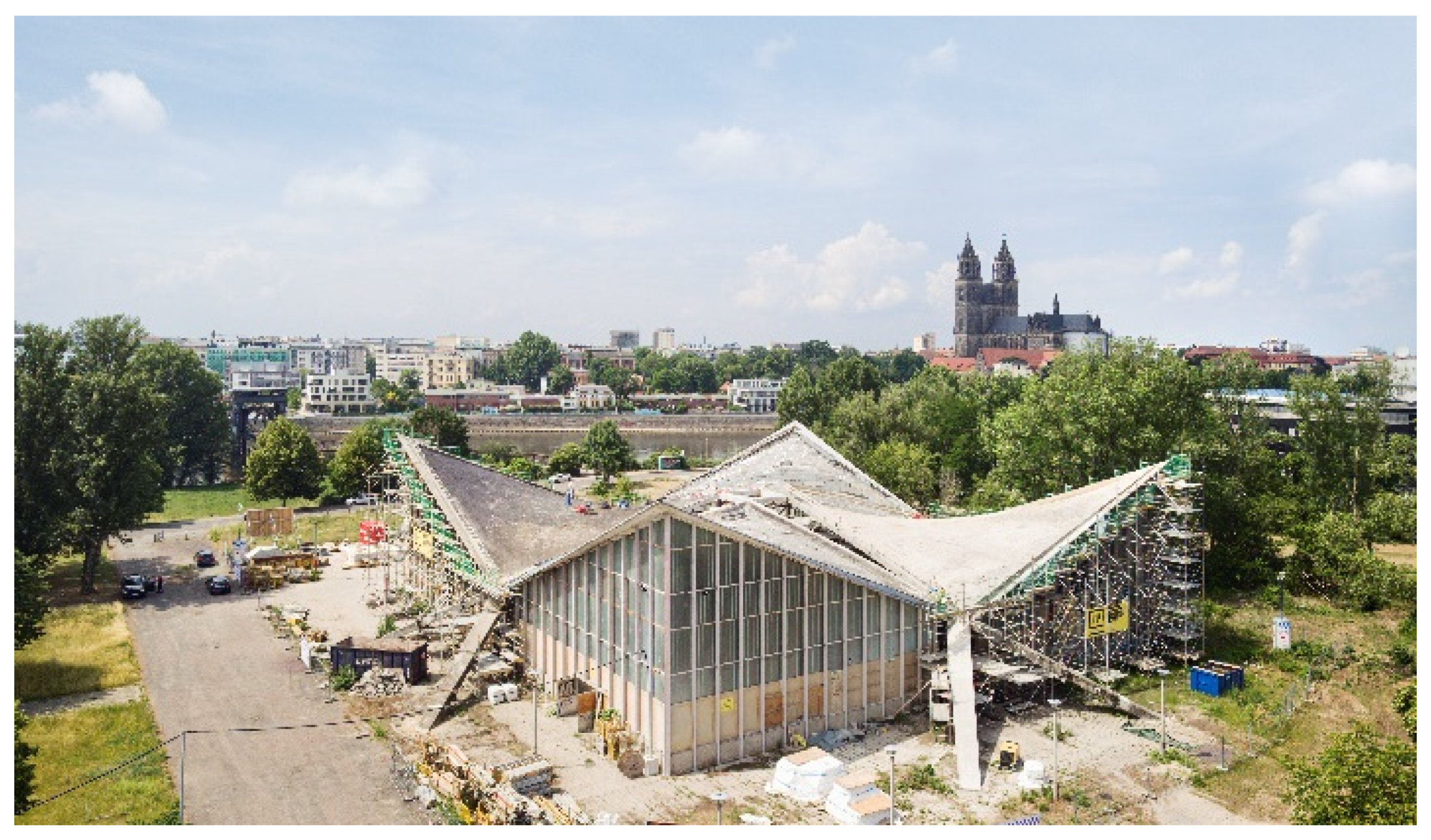
3.2. Strengthening of the Hypar Shell in Magdeburg
3.3. Strengthening of the Beyer Bau in Dresden
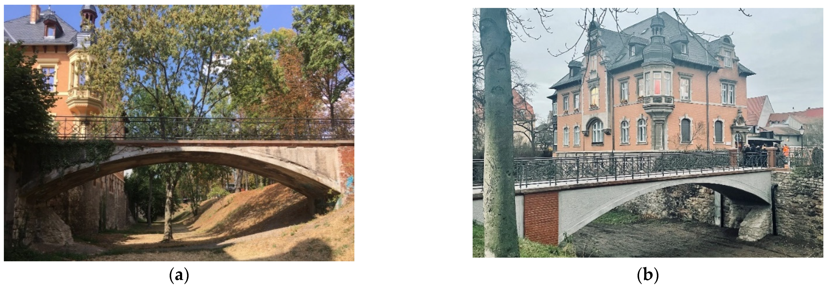
3.4. Strengthening of a Pedestrian Brigde in Naumburg
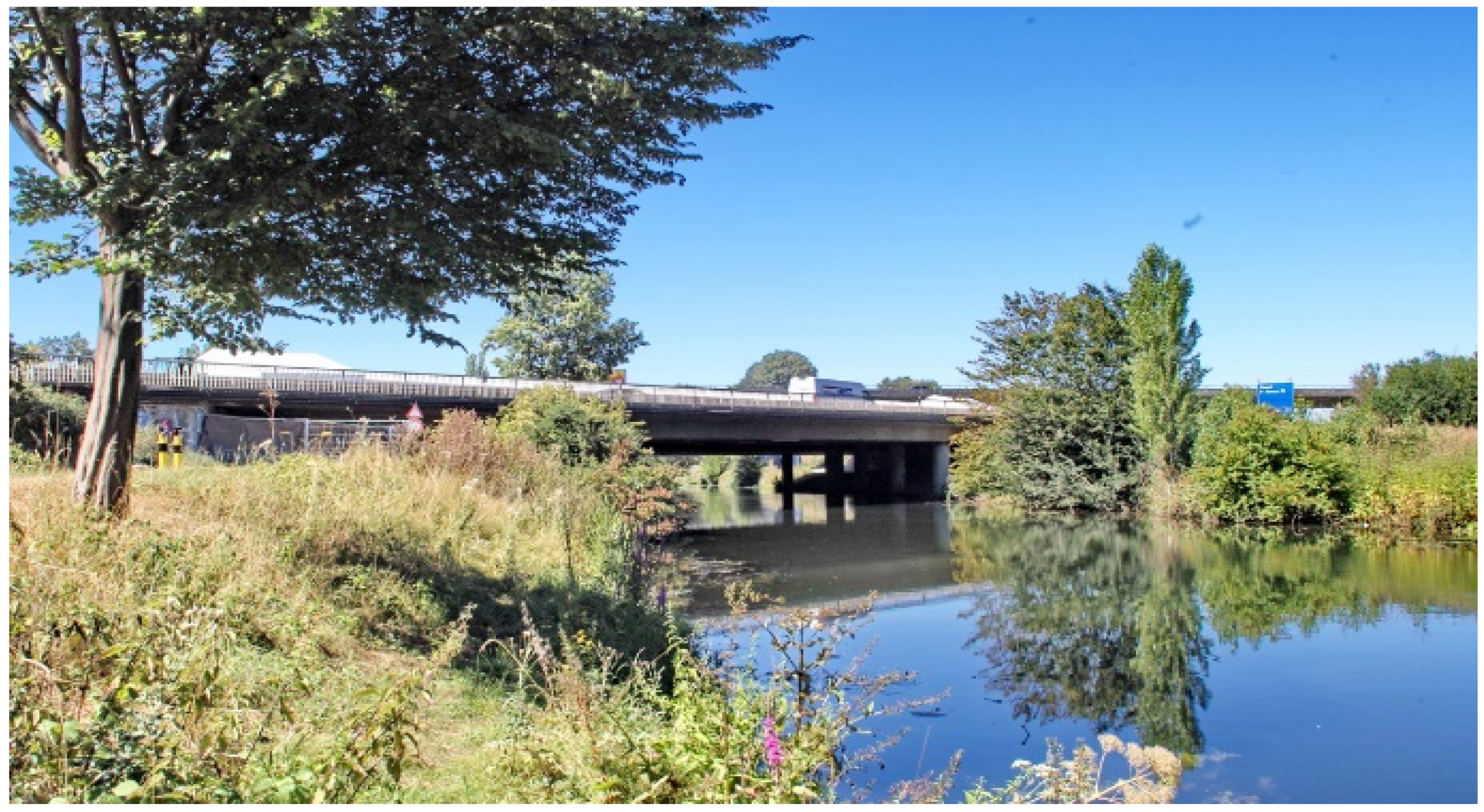
3.5. Strengthening of the First Motorway Bridge in Germany
4. Current Challenges in Research
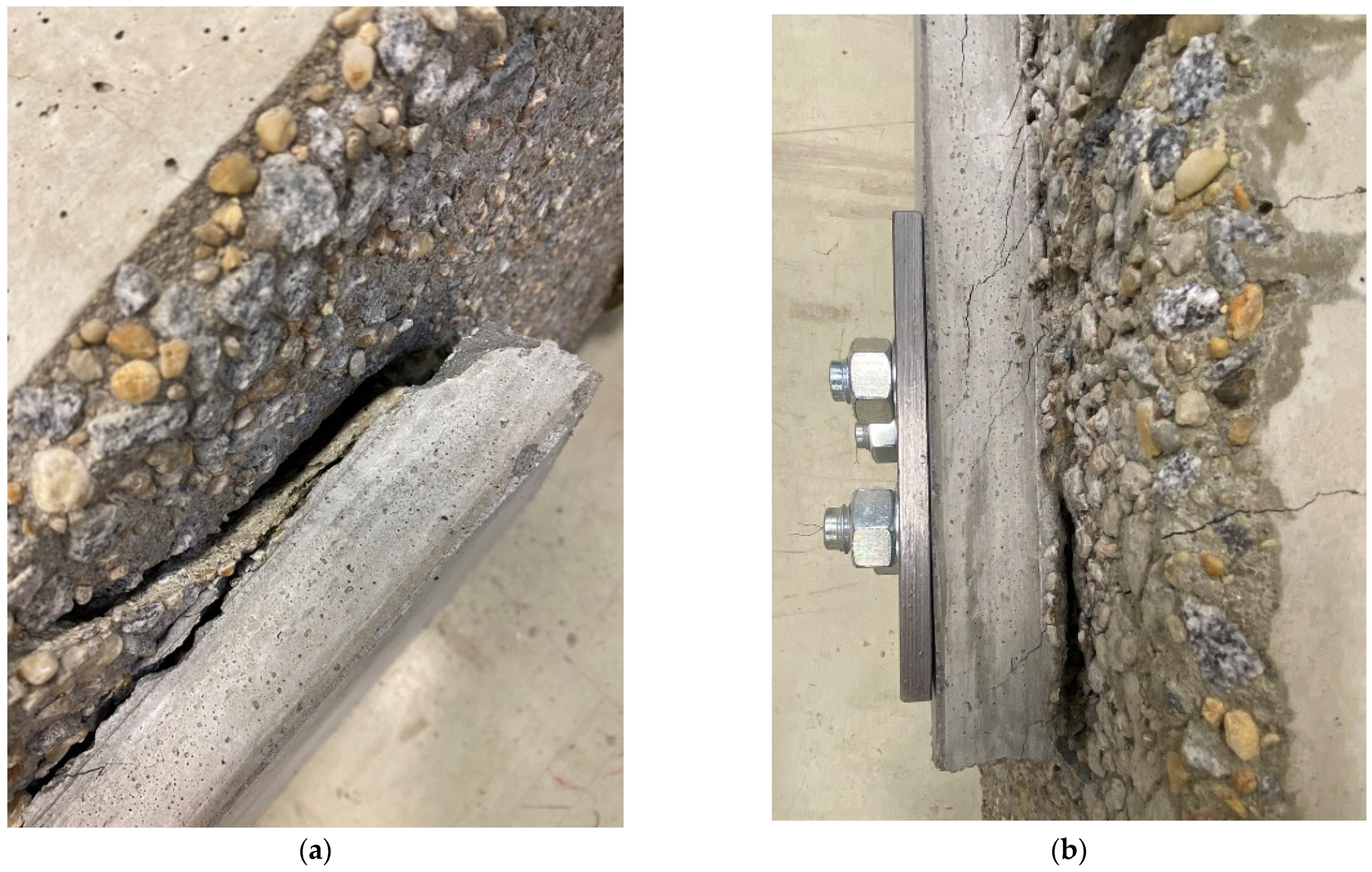
4.1. Strengthening with Carbon Reinforced Concrete—Challenges
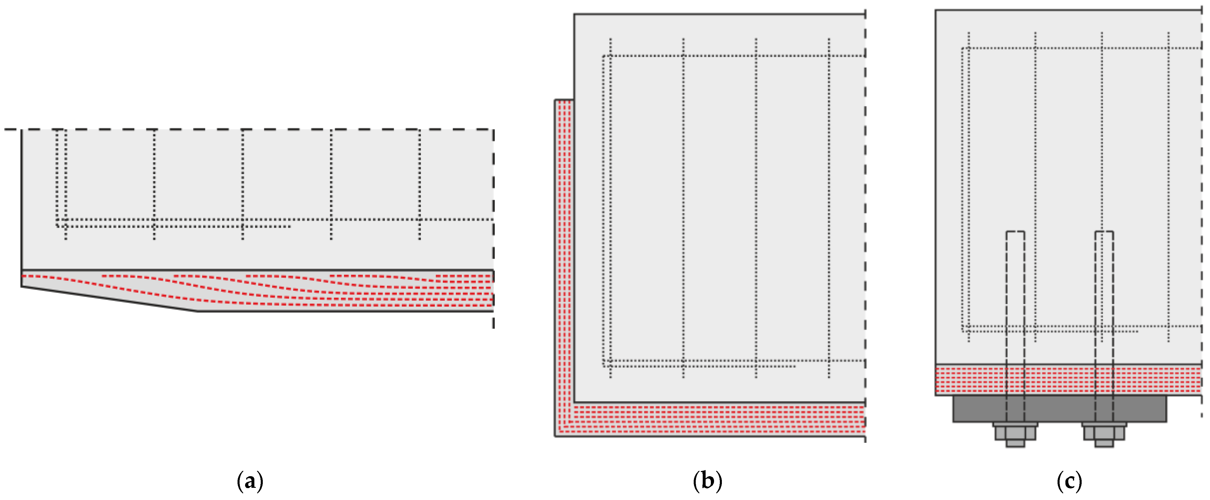
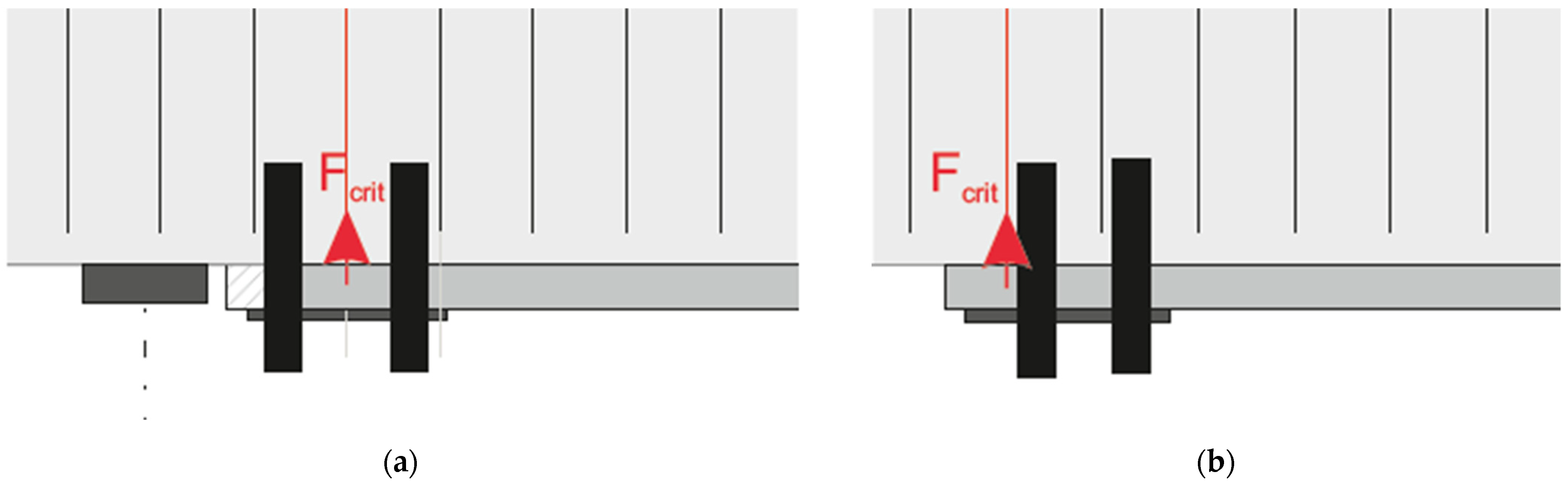
4.2. Possible Solutions to Avoid Concrete Cover Separation
5. Experimental Investigations
5.1. Materials and Methods
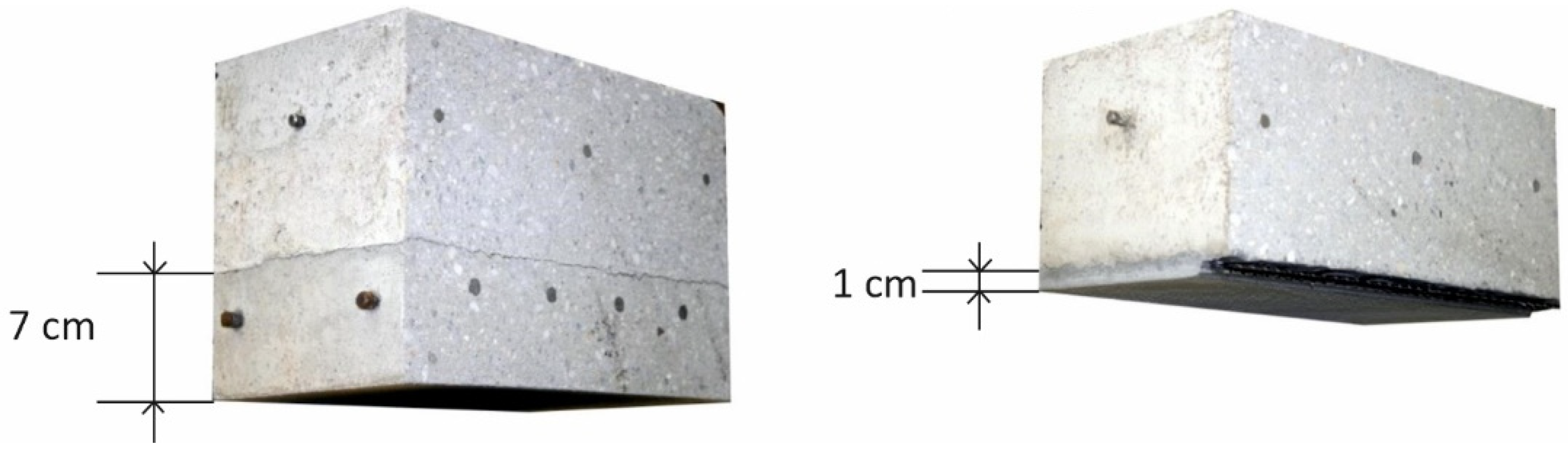
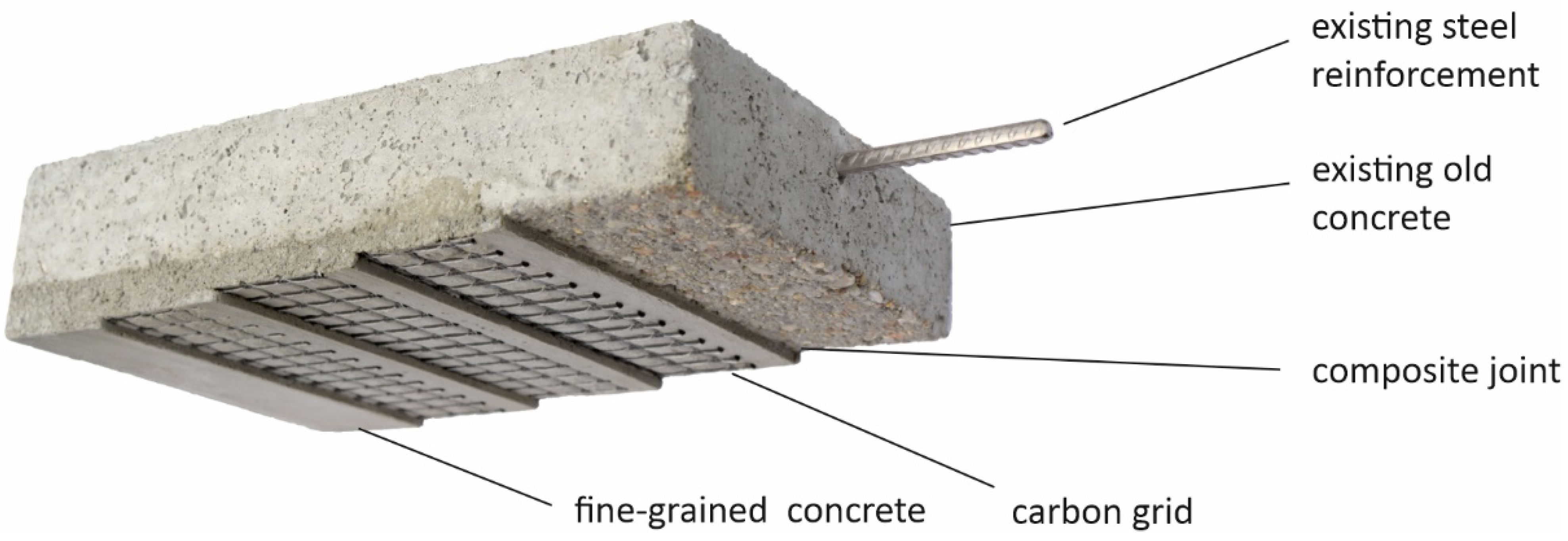
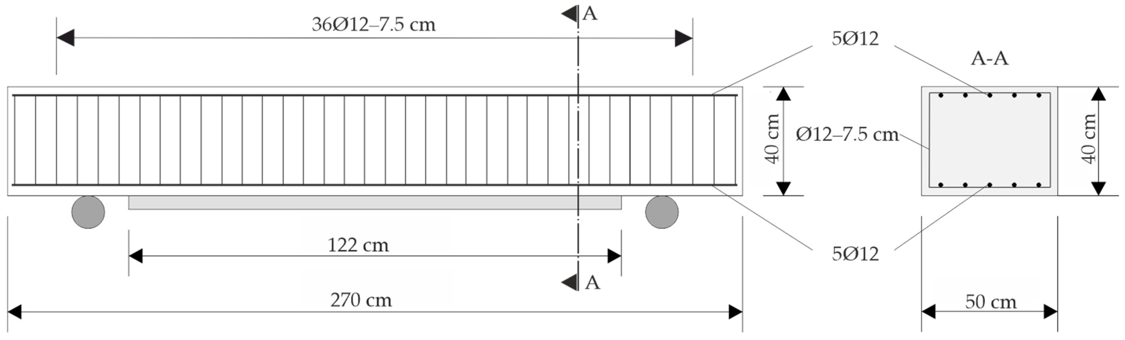
5.1.1. Specimen—Geometry and Material
5.1.2. Manufacturing of the Specimen
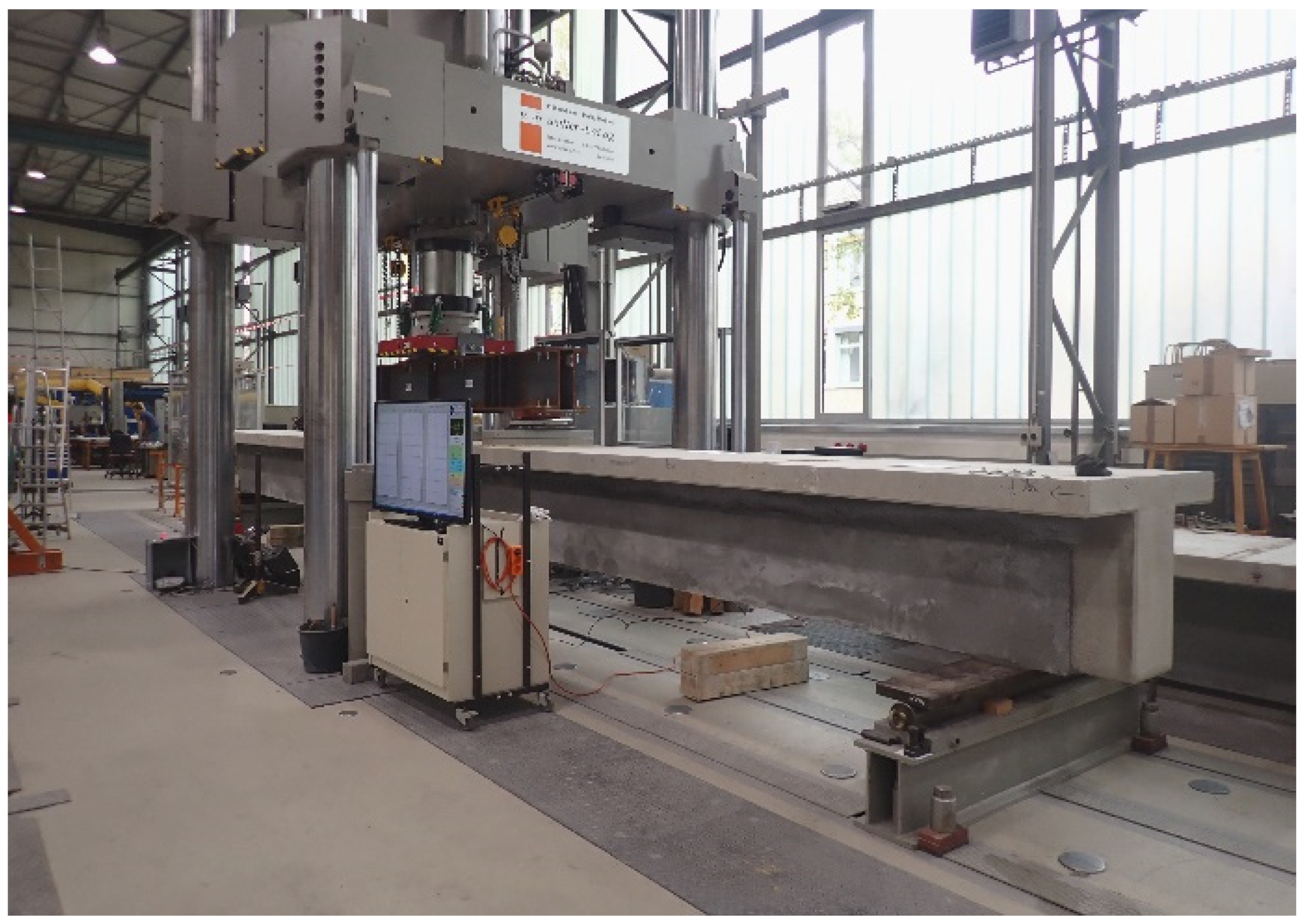
5.1.3. Test Setup and Measuring Technology
- vertical support displacement;
- central deflection;
- strain at the top of the beam in the area of load introduction;
- applied load.
- strain at the bottom center of the strengthening layer;
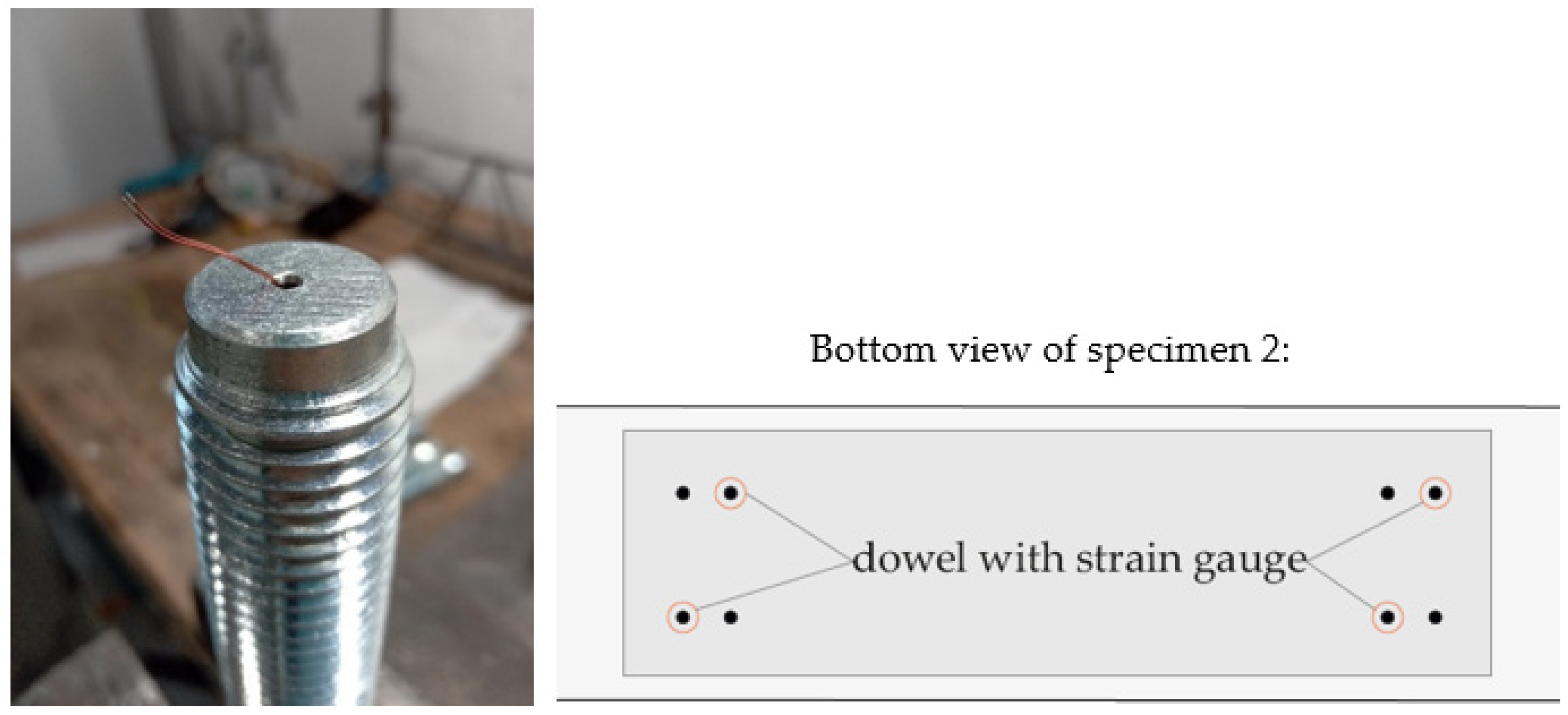
- strain inside two of the four dowels on each side, as shown in Figure 18.
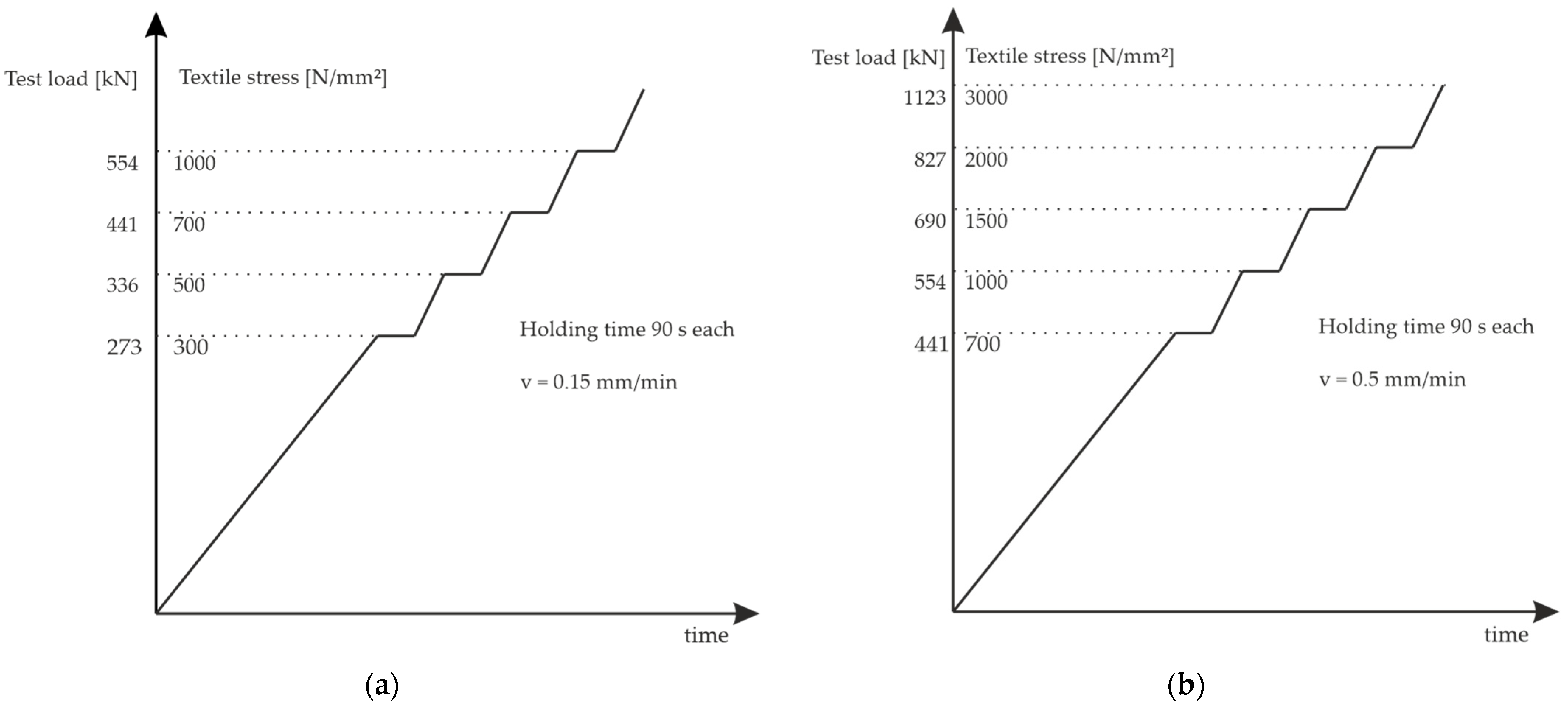
5.1.4. Load Regime and Experimental Program
5.2. Results
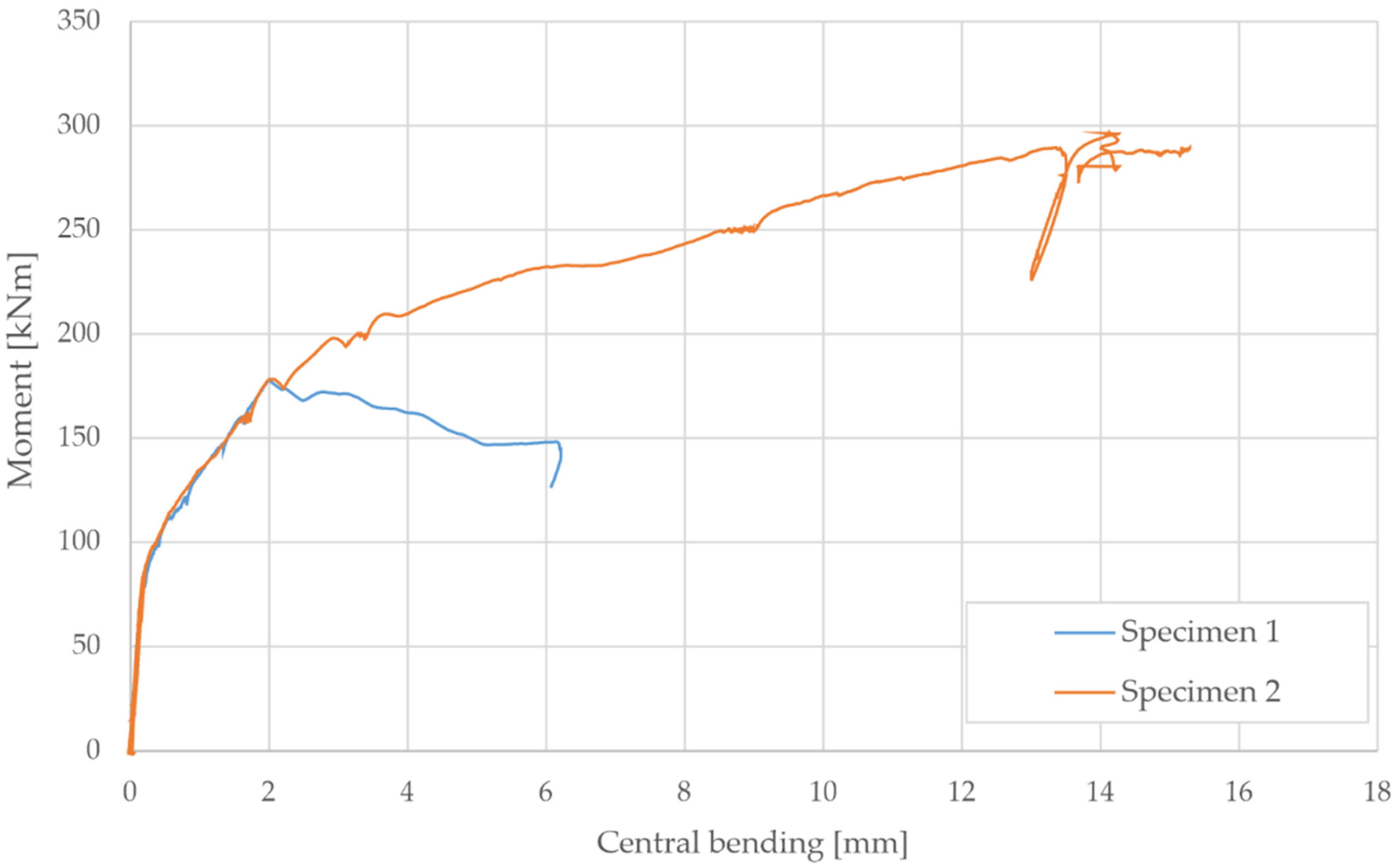
5.2.1. Results of the Bending Tests
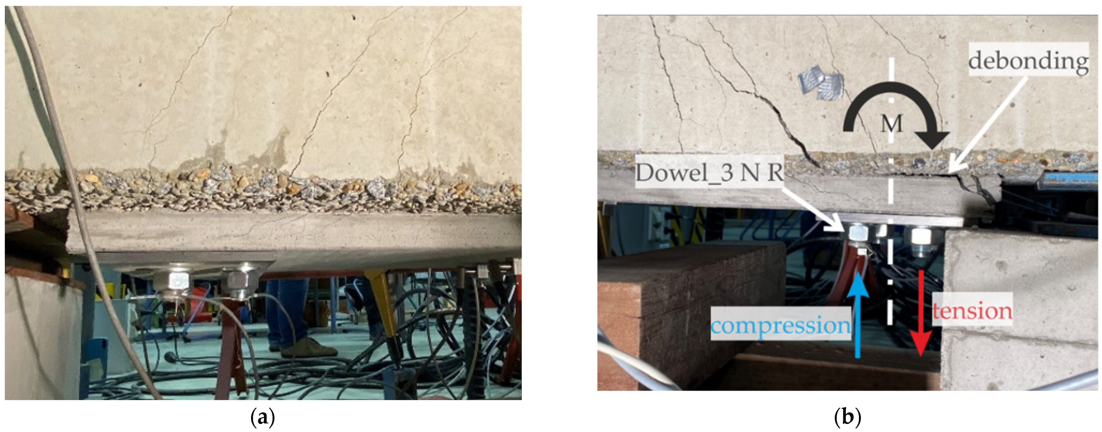
5.2.2. Dowel Loads
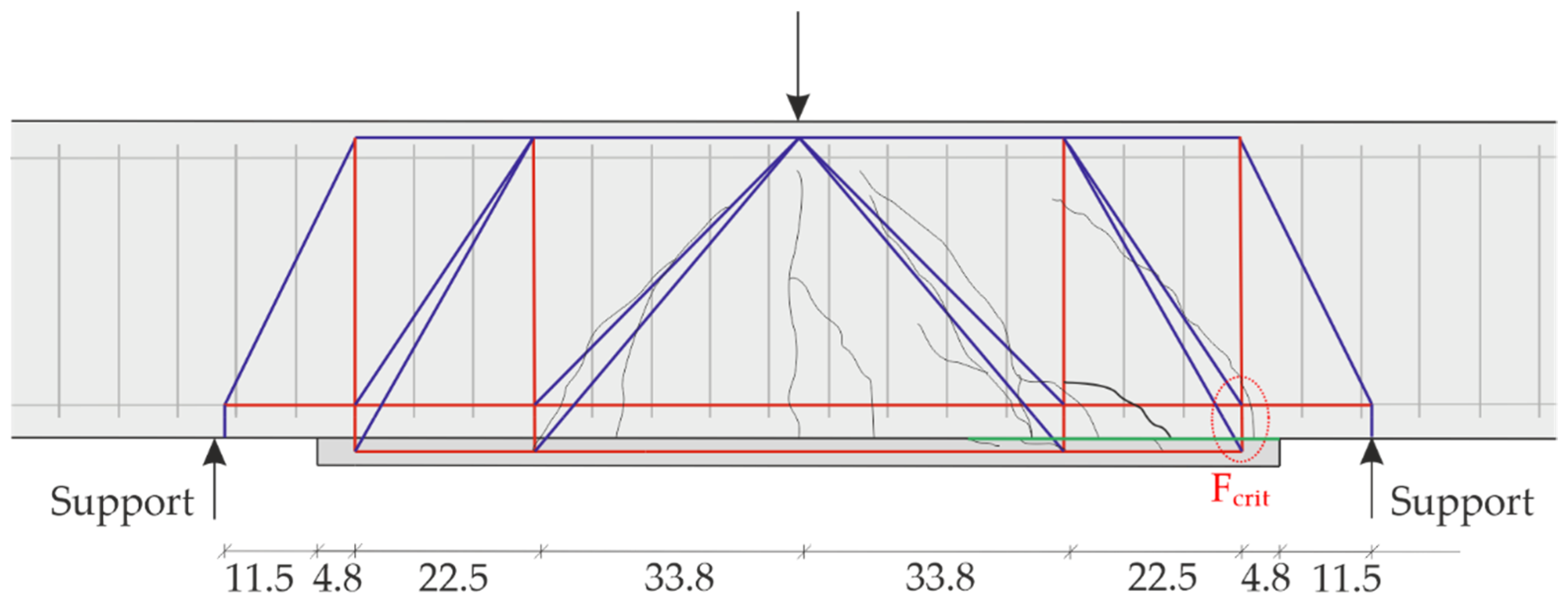
5.2.3. Recalculation of the Experiments
5.3. Discussion of Possible Causes for the Difference between Measured and Calculated Dowel Loads
5.3.1. Overview
- As each testing configuration was only tested on one specimen, the obtained results cannot be assumed as mean values. Therefore, differences due to scattering of the testing results may occur.
- When calculating Fcrit in the strut-and-tie-model, centric tension in the dowels is assumed. However, due to the failure of the bonding area between carbon reinforced concrete and reinforced concrete, bending of the dowels instead of centric tension may also be possible.
- The bores for the strain gauges inside the dowels may not have been located exactly in the center of each dowel. In the case of the dowels receiving little bending, the mean strain of the dowel may be over- or underestimated, and thus also the calculated forces.
- Errors of the measurement of strain inside the dowels may have occurred.
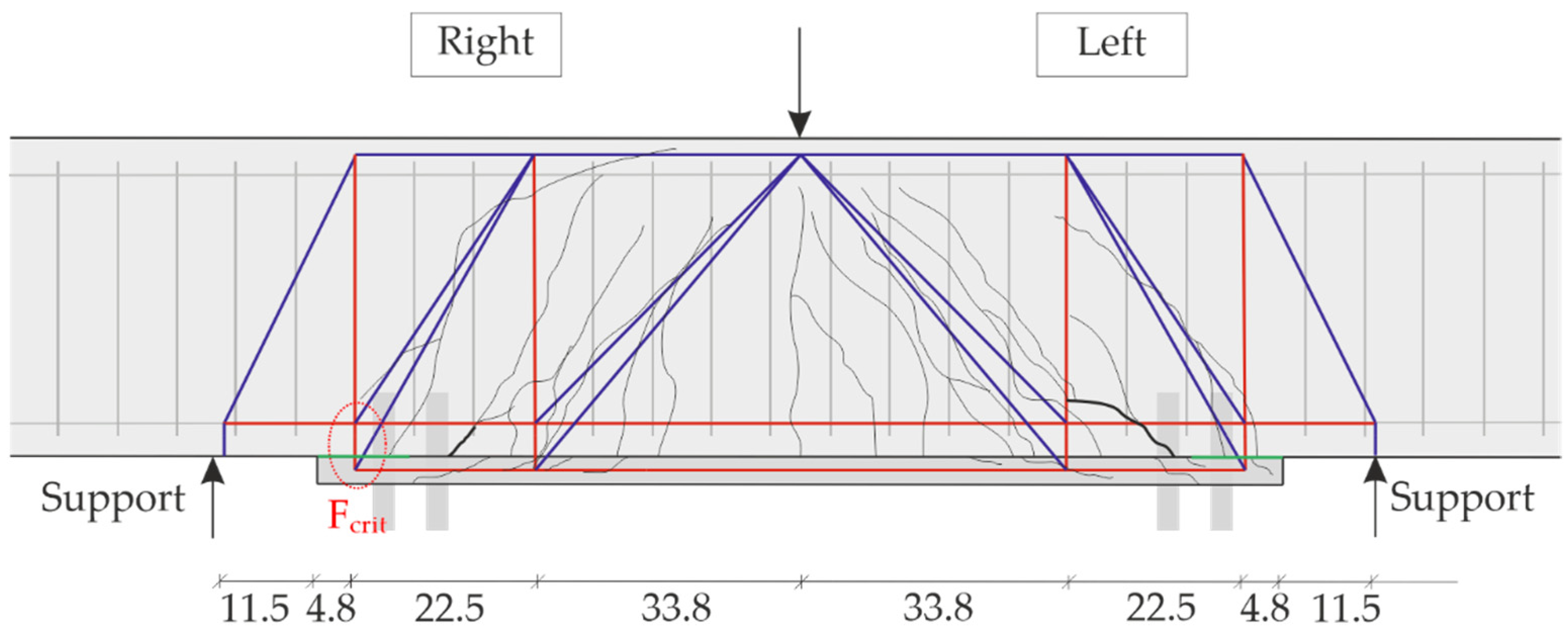
- The location of the resulting force of the dowel group did not match the location of the critical tensile strut. This deviation may lead to differences between the measured and calculated dowel forces.
- As the measured dowel forces were calculated from the measured strains, the difference between the measured and calculated dowel forces may result from assuming a wrong E-modulus for the dowels.
- As the slope of the compression struts of the assumed strut-and-tie-model does not always match the real slope of the cracks of the specimens (especially specimen 2), it may be possible that the assumed strut-and-tie model is incorrect.
- When installing the dowels, they were prestressed by applying a tightening torque of 200 Nm. However, the measuring of the strain of the dowels was only started after prestressing. Therefore, the force inside the dowels due to their prestressing may have to be added to the measured dowel forces.
5.3.2. Discussion of the E-Modulus
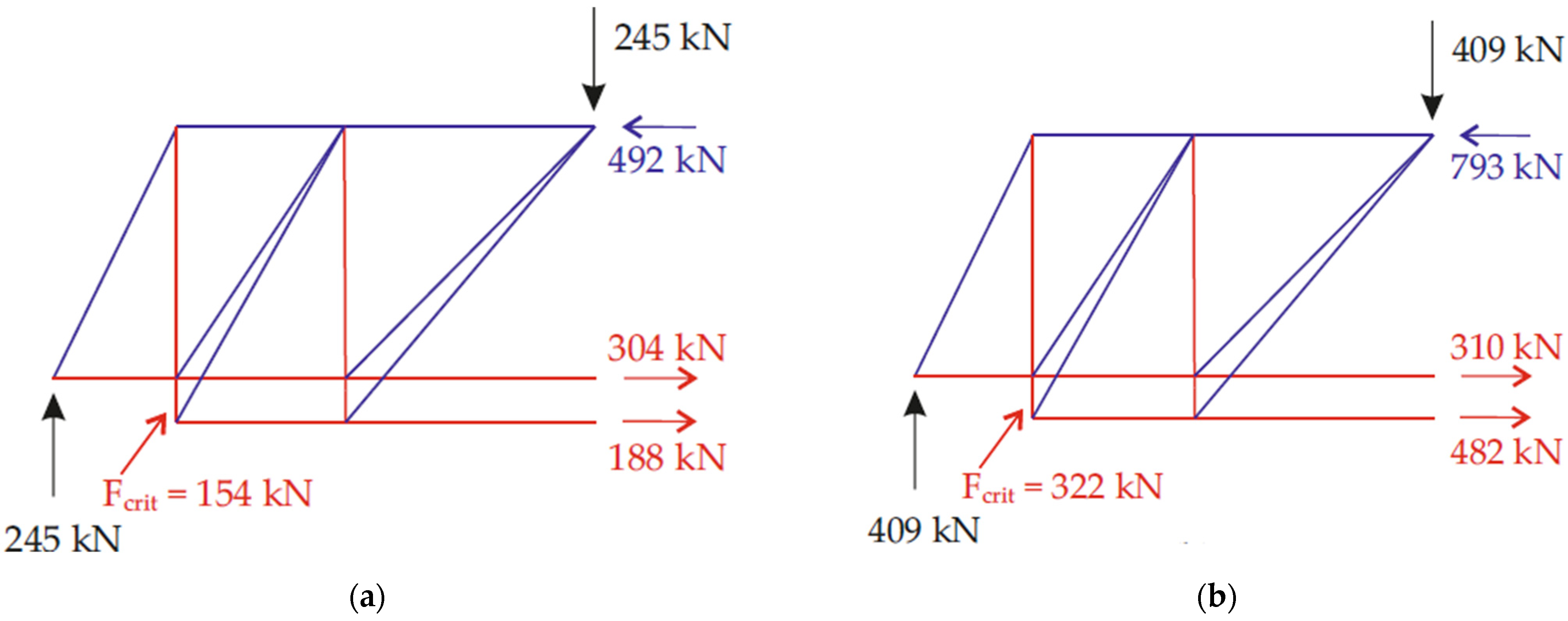
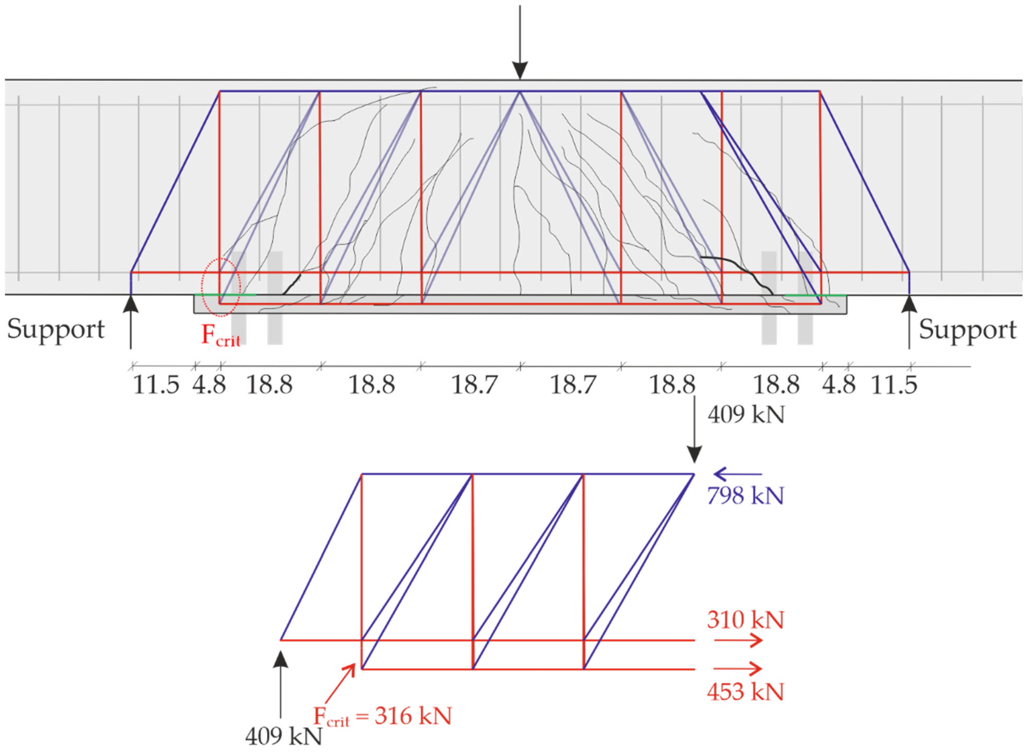
5.3.3. Discussion of the Strut-and-Tie-Model
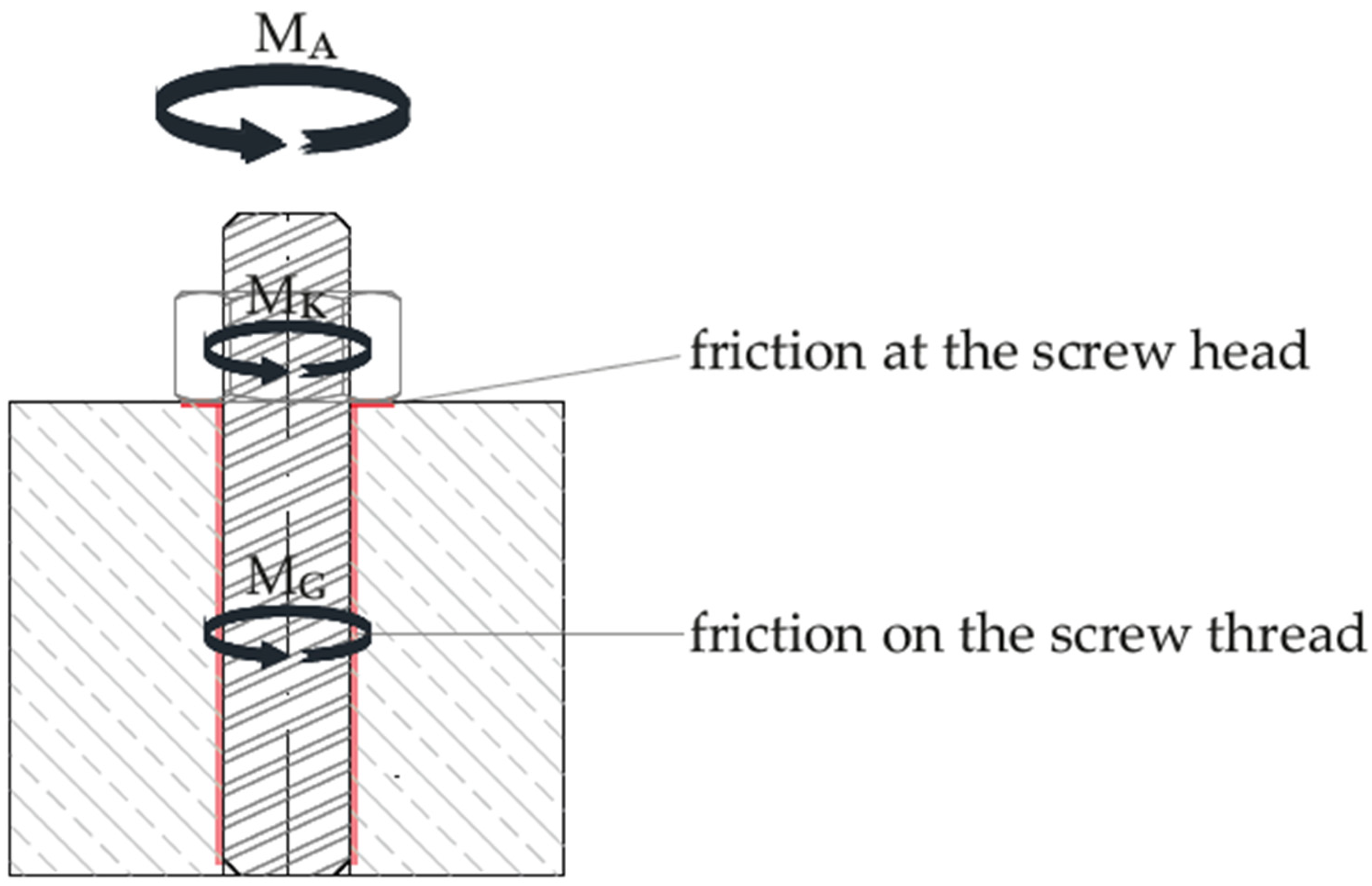
5.3.4. Discussion of the Prestressing of the Dowels
- MA: the tightening torque was set to 200 Nm;
- DKM: the mean diameter of the screw head was set to 37.78 mm, according to [49] for M24 screws;
- μK: the coefficient of friction under the screw head was set to 0.125, according to recommendations for electrogalvanized surfaces (e.g., [50]);
- d2: the pitch diameter of the screw threads was set to 22.051 mm, according to [51] for M24 screws;
- φ: the pitch angle of the screw threads was set to 2.48°, according to [51] for M24 screws;
- α: the flank angle of the screw threads was set to 60°, according to [51] for M24 screws.
6. Conclusions
Author Contributions
Funding
Institutional Review Board Statement
Informed Consent Statement
Data Availability Statement
Acknowledgments
Conflicts of Interest
References
- Weidner, S.; Mrzigod, A.; Bechmann, R.; Sobek, W. Graue Emissionen im Bauwesen—Bestandsaufnahme und Optimierungsstrategien. Beton-Und Stahlbetonbau 2021, 116, 969–977. [Google Scholar] [CrossRef]
- Meier, U. Strengthening of structures using carbon fibre/epoxy composites. Constr. Build. Mater. 1995, 9, 341–351. [Google Scholar] [CrossRef]
- Chajes, M.J.; Thomson, T.A.; Januszka, T.F.; Finch, W.W. Flexural strengthening of concrete beams using externally bonded composite materials. Constr. Build. Mater. 1994, 8, 191–201. [Google Scholar] [CrossRef]
- M’Bazaa, I.; Missihoun, M.; Labossiere, P. Strengthening of Reinforced Concrete Beams with CFRP Sheets. In Proceedings of the ICCI’96, Proceedings of the Fiber Composites in Infrastructure (ICCI’96), Tuscon, AZ, USA, 15–17 January 1996; pp. 746–759. [Google Scholar]
- Bakis, C.E.; Bank, L.C.; Brown, V.; Cosenza, E.; Davalos, J.F.; Lesko, J.J.; Machida, A.; Rizkalla, S.H.; Triantafillou, T.C. Fiber-Reinforced Polymer Composites for Construction—State-of-the-Art Review. J. Compos. Constr. 2002, 6, 73–87. [Google Scholar] [CrossRef] [Green Version]
- Mostofinejad, D.; Shameli, S.M. Externally bonded reinforcement in grooves (EBRIG) technique to postpone debonding of FRP sheets in strengthened concrete beams. Constr. Build. Mater. 2013, 38, 751–758. [Google Scholar] [CrossRef]
- Andrä, H.P.; Maier, M. Post-Strengthening of RC Structures with Externally Bonded Presstressed CFRP Strips. In Proceedings of the 16th IABSE Congress, Luzern, Switzerland, 18 September 2000; pp. 18–21,1507–1514. [Google Scholar]
- Derkowski, W. The First National Application of Pre-Tensioned Composite Strips to Strengthen the Hall Structure. Czas. Tech. 2007, 4, 265–270. [Google Scholar]
- Zdanowicz, Ł.; Seręga, S.; Tekieli, M.; Kwiecień, A. Polymer Flexible Joint as a Repair Method of Concrete Elements: Flexural Testing and Numerical Analysis. Materials 2020, 13, 5732. [Google Scholar] [CrossRef]
- Lye, H.L.; Mohammed, B.S.; Liew, M.; Wahab, M.; Al-Fakih, A. Bond behaviour of CFRP-strengthened ECC using Response Surface Methodology (RSM). Case Stud. Constr. Mater. 2019, 12, e00327. [Google Scholar] [CrossRef]
- Rahim, N.I.; Mohammed, B.S.; Al-Fakih, A.; Wahab, M.M.A.; Liew, M.S.; Anwar, A.; Amran, Y.H.M. Strengthening the Structural Behavior of Web Openings in RC Deep Beam Using CFRP. Materials 2020, 13, 2804. [Google Scholar] [CrossRef]
- Müller, E.; Schmidt, A.; Schumann, A.; May, S.; Curbach, M. Biegeverstärkung mit Carbonbeton. Beton-und Stahlbetonbau 2020, 115, 758–767. [Google Scholar] [CrossRef]
- Schumann, A.; May, S.; Hoinka, J. Paradigmenwechsel im Bauwesen–Gerade richtig oder schon zu spät? Nachhaltiges Bauen im Bestand mit Carbonbeton. Ernst & Sohn Special, Nachhaltiges Bauen 2021, 13–15. [Google Scholar]
- Scheerer, S.; Schladitz, F.; Curbach, M. Textile Reinforced Concrete—From the Idea to a High Performance Material. In Proceedings of the FERRO-11 International Symposium on Ferrocement and 3rd ICTRC International Conference on Textile Reinforced Concrete, Aachen, Germany, 7–10 June 2015; Hrsg. Brameshuber, W., Ed.; RILEM Publications S.A.R.L.: Bagneux, France, 2015; pp. 15–33. [Google Scholar]
- Scheerer, S.; Zobel, R.; Müller, E.; Senckpiel-Peters, T.; Schmidt, A.; Curbach, M. Flexural Strengthening of RC Structures with TRC—Experimental Observations, Design Approach and Application. Appl. Sci. 2019, 9, 1322. [Google Scholar] [CrossRef] [Green Version]
- Brückner, A.; Ortlepp, R.; Curbach, M. Anchoring of shear strengthening for T-beams made of textile reinforced concrete (TRC). Mater. Struct. 2007, 41, 407–418. [Google Scholar] [CrossRef]
- Weiland, S.; Ortlepp, R.; Brückner, A.; Curbach, M. Strengthening of RC-Structures with Textile Reinforced Concrete (TRC). Thin Fiber Text. Reinf. Cem. Syst. 2007, 244, 157–172. [Google Scholar]
- Triantafillou, T. Shear Strengthening of Reinforced Concrete Beams Using Epoxy-Bonded FRP Composites. ACI Struct. J. 1998, 95, 107–115. [Google Scholar]
- Bergmann, S.; May, S.; Hegger, J.; Curbach, M. Shear strengthening of reinforced concrete T-beams using carbon reinforced concrete. Chic. ACI 2020, 345, 169–184. [Google Scholar]
- Bergmann, S.; May, S. Shear Strengthening of RC T-Beams with CRC. In Proceedings of the Tagungsband der 12. Carbon- und Textilbetontage, Dresden, Germany, 22–23 September 2020; pp. 38–41. [Google Scholar]
- Escrig, C.; Gil, L.; Bernat-Maso, E.; Puigvert, F. Experimental and analytical study of reinforced concrete beams shear strengthened with different types of textile-reinforced mortar. Constr. Build. Mater. 2015, 83, 248–260. [Google Scholar] [CrossRef] [Green Version]
- Schumann, A.; Schöffel, J.; May, S.; Schladitz, F.; Curbach, M. Ressourceneinsparung mit Carbonbeton–Am Beispiel der Verstärkung der Hyparschale in Magdeburg. In Nachhaltigkeit, Ressourceneffizienz und Klimaschutz, Konstruktive Lösungen für das Planen und Bauen–Aktueller Stand der Technik; Hrsg. Hauke, B., Institut Bauen und Umwelt e.V., DGNB e.V., Eds.; Ernst & Sohn: Berlin, Germany, 2021. [Google Scholar]
- Schumann, A.; May, S.; Bochmann, J. Zu neuer Leistungsfähigkeit. B + B Bau. Im Bestand 2021, 1, 20–25. [Google Scholar]
- Jesse, F.; Curbach, M. Verstärken mit Carbonbeton. In BetonKalender 2010–Brücken, Betonbau im Wasser; Hrsg. Fingerloos, F., Wörner, J.-D., Eds.; Ernst und Sohn: Berlin, Germany, 2010; pp. 457–565. [Google Scholar]
- Curbach, M.; May, S.; Müller, E.; Schumann, A.; Schütze, E.; Wagner, J. Verstärken mit Carbonbeton. In Beton-Kalender 2022–Nachhaltigkeit, Digitalisierung, Instandhaltung; Hrsg. Bergmeister, K., Fingerloos, F., Wörner, J.-D., Eds.; Ernst und Sohn: Berlin, Germany, 2021; pp. 761–804. [Google Scholar]
- Schumann, A.; Schladitz, F.; May, S.; Scheerer, S. Carbonbeton in der Denkmalsanierung. Denkmalsanierung 2020, 2021, 2–3. [Google Scholar]
- Riegelmann, P.; May, S.; Schumann, A. Das Potential von Carbonbeton für den Brückenbestand-das ist heute schon möglich! In Tagungsband zum 30. Dresdner Brückenbausymposium (Ergänzungsband 2021) (Hrsg. Curbach, M.); Institut für Massivbau der TU Dresden: Dresden, Germany, 2021; pp. 79–90. [Google Scholar]
- Deutscher Ausschuss für Stahlbeton. (German Committee for Reinforced Concrete): Richtlinie Betonbauteile mit nichtmetallischer Bewehrungen; Draft; Deutscher Ausschuss für Stahlbeton: Berlin, Germany, 2022. [Google Scholar]
- Z-31.10-182; Verfahren zur Verstärkung von Stahlbeton mit TUDALIT (Textilbewehrter Beton). abZ, DIBt: Berlin, Germany, 2016.
- Z-31.10-182; CARBOrefit–Verfahren zur Verstärkung von Stahlbeton mit Carbonbeton. abZ, DIBt: Berlin, Germany, 2021.
- EN 196-1:2005; DIN EN 196-1 (2005-05): Methods of Testing Cement-Part 1: Determination of Strength. German Version. 2005. Available online: https://standards.iteh.ai/catalog/standards/cen/211ff288-f8ea-4d1d-b62c-967e4d285f17/en-196-1-2005 (accessed on 9 April 2022).
- Erhard, E.; Weiland, S.; Lorenz, E.; Schladitz, F.; Beckmann, B.; Curbach, M. Anwendungsbeispiele für Textilbetonverstärkung: Instandsetzung und Verstärkung bestehender Tragwerke mit Textilbeton. Beton-und Stahlbetonbau 2015, 110, 74–82. [Google Scholar] [CrossRef]
- Al-Jamous, A.; Uhlig, K. Sanierung der historischen Betonbogenbrücke in Naila. Tag. Zum 2017, 27, 71–78. [Google Scholar]
- Rempel, S.; Erhard, E.; Schmidt, H.-G.; Will, N. Die Sanierung des Mariendomdaches in Neviges mit carbonbewehrtem Spritzmörtel. Beton-Und Stahlbetonbau 2018, 113, 543–550. [Google Scholar] [CrossRef]
- Weiland, S.; Schladitz, F.; Schütze, E.; Timmers, R.; Curbach, M. Rissinstandsetzung eines Zuckersilos. Bautechnik 2013, 90, 498–504. [Google Scholar] [CrossRef]
- Feix, J.; Hansl, M. Pilotanwendungen von Textilbeton für Verstärkungen im Brückenbau. In Tagungsband zum 25. Dresdner Brückenbausymposium–Planung, Bauausführung, Instandsetzung und Ertüchtigung von Brücken; Hrsg. Curbach, M., Ed.; Institut für Massivbau der TU Dresden: Dresden, Germany, 2015; pp. 99–110. [Google Scholar]
- Schladitz, F.; Schumann, A.; May, S.; Curbach, M. Carbonbetonbau im Brückenbau. Zeitschrift des Vereins der Straßenbau-und Verkehrsingenieure im Freistaat Sachsen e.V. 2020, 34–37. [Google Scholar]
- Steinbock, O.; Giese, N.-J.; Curbach, M. Probebelastung einer mit Carbonbeton verstärkten Plattenbrücke. In Tagungsband zum 11. Symposium Experimentelle Untersuchungen von Baukonstruktionen; Hrsg. Curbach, M., Marx, S., Scheerer, S., Hampel, T., Eds.; Institut für Massivbau der TU Dresden: Dresden, Germany, 8 March 2021; pp. 118–129. [Google Scholar]
- Adam, V.; Bielak, J.; Will, N.; Hegger, D.J. Experimentelle Untersuchungen zur Verstärkung von Brückenfahrbahnplatten mit Textilbeton. Beton-und Stahlbetonbau 2020, 115, 952–961. [Google Scholar] [CrossRef]
- Büttner, T. SMART-DECK: Vom Konzept zum Demonstrator. Bautechnik 2019, 97, 48–56. [Google Scholar] [CrossRef]
- Hentschel, M.; Schumann, A.; Ulrich, H.; Jentzsch, S. Sanierung der Hyparschale Magdeburg. Bautechnik 2018, 96, 25–30. [Google Scholar] [CrossRef] [Green Version]
- Riegelmann, P.; Schumann, A.; May, S.; Bochmann, J.; Garibaldi, M.P.; Curbach, M. Müther’s shell structures in Germany—A solution to avoid demolition. Proc. Inst. Civ. Eng.-Eng. Hist. Herit. 2020, 174, 124–132. [Google Scholar] [CrossRef]
- Schumann, A.; Hentschel, M.; Zobel, R.; Curbach, M. Strengthening of the Hypar Shell in Magdeburg with Carbon Reinforced Concrete-Design and Calculations. In Proceedings of the IASS Annual Symposium 2019—Structural Membranes, Barcelona, Spain, 7–10 October 2019; pp. 855–862. [Google Scholar]
- Steinbock, O.; Pelke, E.; Ost, O. Carbonbeton–Eine neue Verstärkungsmethode für Massivbrücken–Teil 1: Grundlagen und Hintergründe zum Pilotprojekt “Brücken über die Nidda im Zuge der BAB A 648”. Beton-und Stahlbetonbau 2021, 116, 101–108. [Google Scholar] [CrossRef]
- Steinbock, O.; Bösche, T.; Schumann, A. Carbonbeton–Eine neue Verstärkungsmethode für Massivbrücken–Teil 2: Carbonbeton im Brückenbau und Informationen zur Zustimmung im Einzelfall für das Pilotprojekt “Brücken über die Nidda im Zuge der BAB A 648”. Beton-und Stahlbetonbau 2021, 116, 109–117. [Google Scholar] [CrossRef]
- Steinbock, O.; Teworte, F.; Neis, B. Carbonbeton–Eine neue Verstärkungsmethode für Massivbrücken–Teil 3: Planung und Umsetzung der Verstärkungsmaßnahme mit Carbonbeton am Pilotprojekt „Brücken über die Nidda im Zuge der BAB A 648“. Beton-und Stahlbetonbau 2021, 116, 118–126. [Google Scholar] [CrossRef]
- Finckh, W. Einfluss Bauteilspezifischer Effekte auf die Bemessung von mit CFK-Lamellen Verstärkten Stahlbetonbauteilen. Ph.D. Thesis, Technische Universität München, Lehrstuhl für Massivbau, München, Italy, 2012. [Google Scholar]
- ETA-99/0011; Würth Fixanker W-FAZ und W-FAZ-IG—Mechanische Dübel zur Verwendung im Beton. DIBt: Berlin, Germany, 2018.
- DIN 7990: 2017-08; Sechskantschrauben mit Sechskantmutter für Stahlkonstruktionen. Beuth: Berlin, Germany, 2017.
- Available online: https://www.schrauben-frank.de/technische-informationen/mechanische-eigenschaften/anziehen-v.-schrauben-und-reibwerte/ (accessed on 15 March 2022).
- DIN 13-1:1999-11; Metrisches ISO-Gewinde Allgemeiner Anwendung–Teil 1: Nennmaße für Regelgewinde; Gewinde-Nenndurchmesser von 1mm bis 68 mm. Beuth: Berlin, Germany, 1999.
- Available online: https://media.wuerth.com/stmedia/shop/masterpages0000/LANG_de/09146.pdf (accessed on 15 March 2022).


| Characteristics | Unit | Value |
|---|---|---|
| Compressive strength (characteristic value after 28 days) 1 | [N/mm2] | ≥80 |
| Flexural tensile strength (characteristic value after 28 days) 1 | [N/mm2] | ≥6 |
| E-modulus (mean value after 28 days) | [N/mm2] | ≥25,000 |
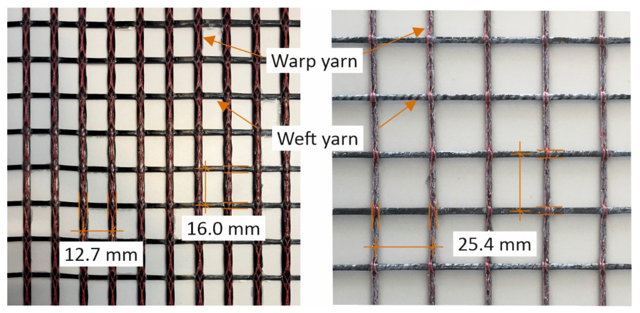
| Version | Property | Unit | Warp Yarn | Weft Yarn |
|---|---|---|---|---|
| Standard | Fiber content | [K] | ≥48 and ≤50 | 12 |
| Cross-sectional area of the yarns | [mm2] | ≥1.8 and ≤1.95 | 0.45 | |
| Yarn spacing | [mm] | 12.7 | 16 +0/−2 | |
| Special | Fiber content | [K] | ≥48 and ≤50 | ≥12 and ≤50 |
| Cross-sectional area of the yarns | [mm2] | ≥1.8 and ≤1.95 | ≥0.45 and ≤1.95 | |
| Yarn spacing | [mm] | ≥12.7 and ≤50.8 | ≥16 +0/−2 and smaller than twice the yarn distance in warp direction | |
| Additional requirements | [–] | ≥20% of the cross-sectional area in warp direction |
| Property | Unit | Type 1 | Type 3 |
|---|---|---|---|
| Characteristic tensile strength | [N/mm2] | 1550 | 2250 |
| Design tensile strength | [N/mm2] | 768 | 1300 |
| E-modulus | [N/mm2] | 206,667 | 206,667 |
| Max. strengthening force | [kN/m] | 430 | 430 |
| Design bond strength | [N/mm] | 0.564 | 4.7 |
| Anchoring length | [mm] | 2450 | 500 |
| Flexibility | [–] | very bendable | less bendable |
| Reduction Factors | Type 1 | Type 3 |
|---|---|---|
| Tensile strength | ||
| Temperature influence (40 °C) | 0.85 | 1.00 |
| Long term load | 0.70 | 0.70 |
| Durability | 1.00 | 1.00 |
| Bond strength | ||
| Temperature influence (40 °C) | 0.45 | 1.00 |
| Long term load | 0.47 | 0.70 |
| Durability | 1.00 | 1.00 |
| Specimen | Doweling of the Strengthening Layer? | Sample Number |
|---|---|---|
| 1 | no | 1 |
| 2 | yes | 1 |
| Specimen | Failure Load [kN] | Resulting Moment [kNm] | Max. Textile Stress [N/mm2] |
|---|---|---|---|
| 1 | 490 | 178 | 778 |
| 2 | 818 | 296 | 1965 |
Publisher’s Note: MDPI stays neutral with regard to jurisdictional claims in published maps and institutional affiliations. |
© 2022 by the authors. Licensee MDPI, Basel, Switzerland. This article is an open access article distributed under the terms and conditions of the Creative Commons Attribution (CC BY) license (https://creativecommons.org/licenses/by/4.0/).
Share and Cite
Wagner, J.; Würgau, C.; Schumann, A.; Schütze, E.; Ehlig, D.; Nietner, L.; Curbach, M. Strengthening of Reinforced Concrete Structures with Carbon Reinforced Concrete—Possibilities and Challenges. CivilEng 2022, 3, 400-426. https://0-doi-org.brum.beds.ac.uk/10.3390/civileng3020024
Wagner J, Würgau C, Schumann A, Schütze E, Ehlig D, Nietner L, Curbach M. Strengthening of Reinforced Concrete Structures with Carbon Reinforced Concrete—Possibilities and Challenges. CivilEng. 2022; 3(2):400-426. https://0-doi-org.brum.beds.ac.uk/10.3390/civileng3020024
Chicago/Turabian StyleWagner, Juliane, Carolin Würgau, Alexander Schumann, Elisabeth Schütze, Daniel Ehlig, Lutz Nietner, and Manfred Curbach. 2022. "Strengthening of Reinforced Concrete Structures with Carbon Reinforced Concrete—Possibilities and Challenges" CivilEng 3, no. 2: 400-426. https://0-doi-org.brum.beds.ac.uk/10.3390/civileng3020024