1. Introduction
The renovation and the conversion of historic buildings to host new functions or to update the existing ones may often lead to relevant architectural challenges: the need to rethink internal distribution due to use and privacy reasons without significantly altering the original typological layout, the request to improve the building response in terms of indoor comfort and energy savings without compromising the aesthetic and cultural value of its surfaces (i.e., frescos, decorated walls or ceilings, paving, or other relevant features), the need to obtain additional spaces without introducing extensions that may alter the overall configuration. The level of complexity and of constraints clearly depends on the case-specific conditions, however some common design strategies adopted to provide adequate answers can be identified. Among them, a frequently adopted solution is that based on covering inner courtyard spaces. This choice is often related to the need to reshape internal circulation as happens in the case of Santa Marta’s military building in Verona which has been converted by Massimo Carmassi into the headquarters of the local university concentrating the main vertical circulation elements in the three inner courtyards. Courtyards are often the core element of the building layout and, for this reason, they often offer the opportunity to be transformed into a free circulation space distributing the users to the different wings of the building as happens in the renowned example of British Museum by Norman Foster or into a new hall as happens in the renovation of the Maritime Museum in Amsterdam by Ney and Partners, Dok Architecten, and Rappange and Partners. The courtyards can be also transformed into exhibition spaces as David Chipperfield carried out with his intervention at Neus Museum in Berlin.
Appendix A provides some examples where renowned examples are associated with the new courtyard function and the related adopted technological solution for covering them. The most recurrent solution is a glazed surface—that may assume very different forms and shapes—supported by steel elements directly connected to the surrounding walls (i.e., Museum De Lakenhal by Happel Cornelisse Verhoeven, Julian Harrap Architects) or to new columns of different forms and sections (i.e., Jewish Museum in Berlin by Daniel Libeskind). Few examples explore other construction options such as the use of translucent or transparent membranes (i.e., Beyazit State Library by Tabanlioglu Architects).
It can be noted that in most of the cases the main driver in the decision to cover the courtyard is strictly connected to architectural issues and the effects on the derived indoor environment are often simply assumed as consequences of this process. Despite the quality of the obtained spaces in terms of microclimate and light control having to be considered as a major issue, it is frequently more dependent on heating/cooling systems rather than the architectural and technological concept. Furthermore, architectural design choices may often underestimate the different impacts of the glazed surface during summer and winter when the space is supposed to be adequate in its response to opposite climatic stimuli. The act of covering courtyards or atria produces a new “volume”, enclosed by the building façades and the new added roof, with a related variation of indoor microclimate.
The history of architecture provides some relevant examples of covered courtyards where extensive glass layers were introduced without properly considering the risk of overheating when appropriate ventilation was not provided. An exemplary case of this phenomenon is Villa Medici La Petraia (Florence, Italy) [
1] where the covering of the inner courtyard realized during the XIX century altered the original microclimate, increasing temperature over 38 °C during summer.
The most recurrent technical solutions to cover courtyards and atria can be classified as follows:
Roof based on metal structure (steel, iron, cast iron, etc.) with glass layer;
Roof based on steel structure and cables stiffening with glass layer;
Roof based on glass layer suspended by steel cables;
Roof based on textile membrane;
Roof based on translucent/transparent membrane.
The new covering can be a traditional roof anchored to the surrounding walls (in most of cases a steel and glass structure) or a mobile system (frequently a textile membrane supported by cables) or a fixed system with mobile elements for ventilation purposes.
During the last decade the use of textile membrane, that recalls Frei Otto’s tensile works and connote large structures, has been also adopted in smaller spaces due to the specific material properties able to satisfy a number of different requirements, such as the structural (tensile strength, wind solicitation, fireproofing, etc.), the physical (acoustic, thermal, lighting, etc.) and aesthetic (shape, colour, geometry, etc.) requirements, while having an extremely limited weight compared to conventional glass surfaces. If the average weight of a double paned surface is approximately 20 kg/m
2 (increasing to 30 kg/m
2 in the case of triple paned surface), a three layer ethylen-tetrafluorethylen (ETFE) membrane is only 1.05 kg/m
2 [
2]. This significantly increases the opportunity to adopt a movable system, while reducing the sections of the supporting elements.
The definition of an appropriate configuration is a main design concern not simply in terms of architectural impacts (which are often the most evident outcome) but also in terms of microclimate variation on the space becoming an interior, impacting on air temperature and relative humidity. During the winter season, the greenhouse effect produced by the covering leads to the increase of air temperature due to the solar gain and the reduction of thermal dispersions. During the summer season, when the outdoor temperature may rise over 30 °C (especially in southern European countries such as Spain, Italy and Greece), the same effect generates an unsuitable overheating effect that produces very uncomfortable living conditions.
For this reason, most coverings are provided with mobile elements to ensure natural ventilation or are designed as mobile structures to change their configuration during the different conditions. This can be planned seasonally or driven by sensors detecting external climatic/meteorological conditions or set according to specific indoor conditions suitable for courtyard use.
The study reported in this paper has been carried out to support the definition of a protocol to manage the actuation of the mobile covering which is supposed to be installed in a case study building courtyard. The study adopts the algorithm of technical standard EN ISO 13790 to assess the impact of different technological solutions and geometrical configuration for driving both design and management processes. It must be remarked that the proposed algorithm is intended as a speedy evaluation methodology to explore the effects of alternative design and construction options during a preliminary design phase and it is not intended as a substitutive tool for a detailed design process at all levels.
The literature on the microclimatic characteristics of (open and covered) courtyards, on the related modelling, and analysis includes several studies addressing the issue from different perspectives and at different scales. Yang and Lin’s study [
3] on “an integrated outdoor space design procedure” reports different configurations of urban courtyards, relating geometric characteristics to climatic (air temperature) and physiological equivalent temperature (PET). At the scale of the individual courtyard, Taleghani et al. [
4] similarly reports a research considering different proportions and orientations to which the amount of energy from solar radiation and the related operating temperatures are associated. As courtyards are assumed to be open spaces, the operating temperature depends exclusively on the orientation and solar radiation. The theoretical study by Martinelli and Matzarakis [
5], focussing on the relationship between court geometry and climatic data, confirms the influence of height/width proportion with relation to solar radiation gain (and to the effect of direct/indirect shadowing). Forouzandeh [
6] uses ENVI-met simulation software (
https://www.envi-met.com/) to evaluate semi-covered courtyards, while Chatzidimitrious and Yanna [
7] focus on the shape and materials properties. At the same scale, the work by Almhafdy et al. [
8] investigates the relation between courtyard design configurations and microclimate performances, using the dynamic calculation software IES.VE (
https://www.iesve.com/), comparing simulated data and on site measured data. Dynamic calculation software is also used in the aforementioned study on Villa La Petraia [
1]. Taleghani et al. [
4] and Karakounos et al. [
9] report the outcomes of the evaluation performed with ENVI-met simulation software at block scale on open courtyards and a similar approach is adopted by Almhafdy et al. [
8] in their studies.
At individual courtyard level, several studies focus on the thermal function of internal courtyards in different climatic contexts, as in Soflaei et al. [
10] and Ghaffarianhoseini et al. [
11] in Malaysia, Berkovic et al. [
12] in Israel, Sharples and Bensalem [
13] in Iran, Sadafi et al. [
14] in tropical areas and Taleghani et al. [
4] in The Netherlands. Other studies are, instead, referred to the impacts of wind and passive cooling effects [
15,
16], as well as air pollution [
17].
The aforementioned studies focus on open and uncovered courtyards, through the use of two modelling tools: ENVI-met to evaluate the outdoor microclimate—and, consequently, the relationship between courtyard and the surrounding buildings of the block in which the courtyard is located—and IES.VE that adopts the energy plus calculation engine. Except for Fabbri et al. [
1,
18], the cited works are not directly addressed to explore the modelling of covered, semi-covered or movable roofs and generally a quite limited experience in this field is reported in the specific literature. Therefore, the investigation of modelling approaches capable of considering the microclimatic conditions and, in particular, air temperature inside covered, semi-covered and mobile roofed courtyards, is an open and interesting field of action.
3. Research Methodology: The Simplified Algorithm
3.1. Preliminary Considerations
The research method considers that energy exchanges take place according to a steady-state regime, in accordance with ISO 13790 [
19] indications, with hourly input data. In particular, Annex E “Heat transfer and solar heat gains of special elements” of ISO 13790 was used for this scope. In this way, the algorithm is consistent with the calculation standards of the energy performance of buildings. Compared to the use of dynamic models such as Energyplus (
https://energyplus.net/), Trynsys (
http://www.trnsys.com/), etc. or ISO 52016 [
20], which are usually very time consuming, the adopted algorithm provides a rapid evaluation criterion aimed at ensuring adequate decisional support for managing the spaces within the covered courtyard. The study also intends to evaluate the variation of the air-temperature inside the covered courtyard, comparing the typical situation (open courtyard) and that generated in the case that the court is covered.
The methodology adapts the calculation criterion described by ISO 13790 [
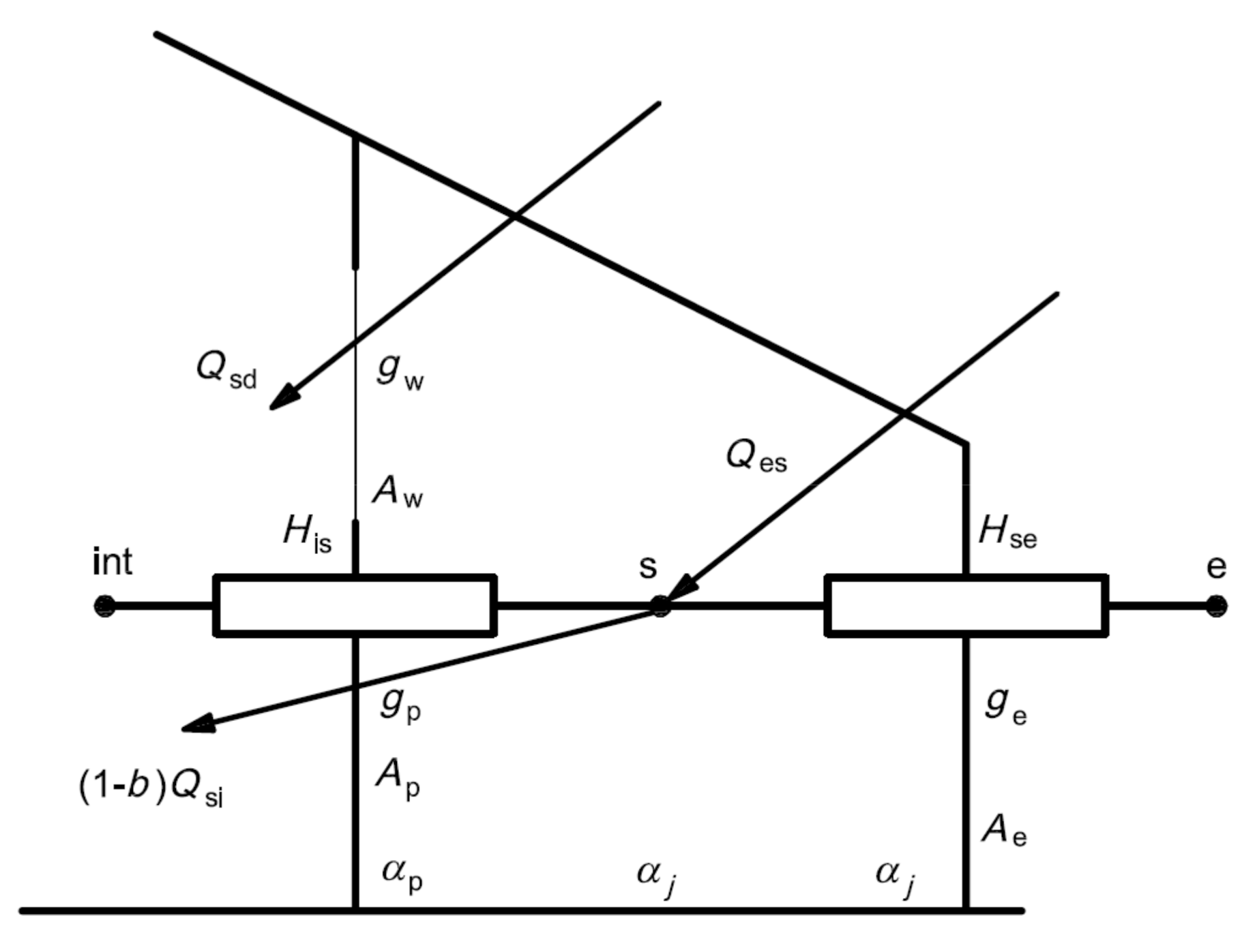
19] Annex E to the covered courtyards. Chapter E.2.3 “Solar heat gains” specifically reports the calculation method of “The solar heat gains entering the conditioned space from the sunspace are the sum of direct solar heat gains, via the sunspace through the partition wall and indirect heat gains through the partition wall from the sunspace heated by the sun”. The model proposed by the standard (
Figure 1) has been applied to the specific case of the covered courtyard considering it as an “attached sunspace” with a single element irradiated by the sun, namely the roofing (
Figure 2).
The model allows assessment of the amount of energy stored due to solar radiation (solar heat gains) within the space of the covered courtyard. Following the process described in the subsequent paragraphs, the air-temperature values and trends inside the covered courtyard can be obtained.
Table 1 summarises the nomenclature of data to be collected for the transparent part of the partition wall (Subscript w), and for the sunspace external envelope (Subscript e).
3.2. Case Study Description
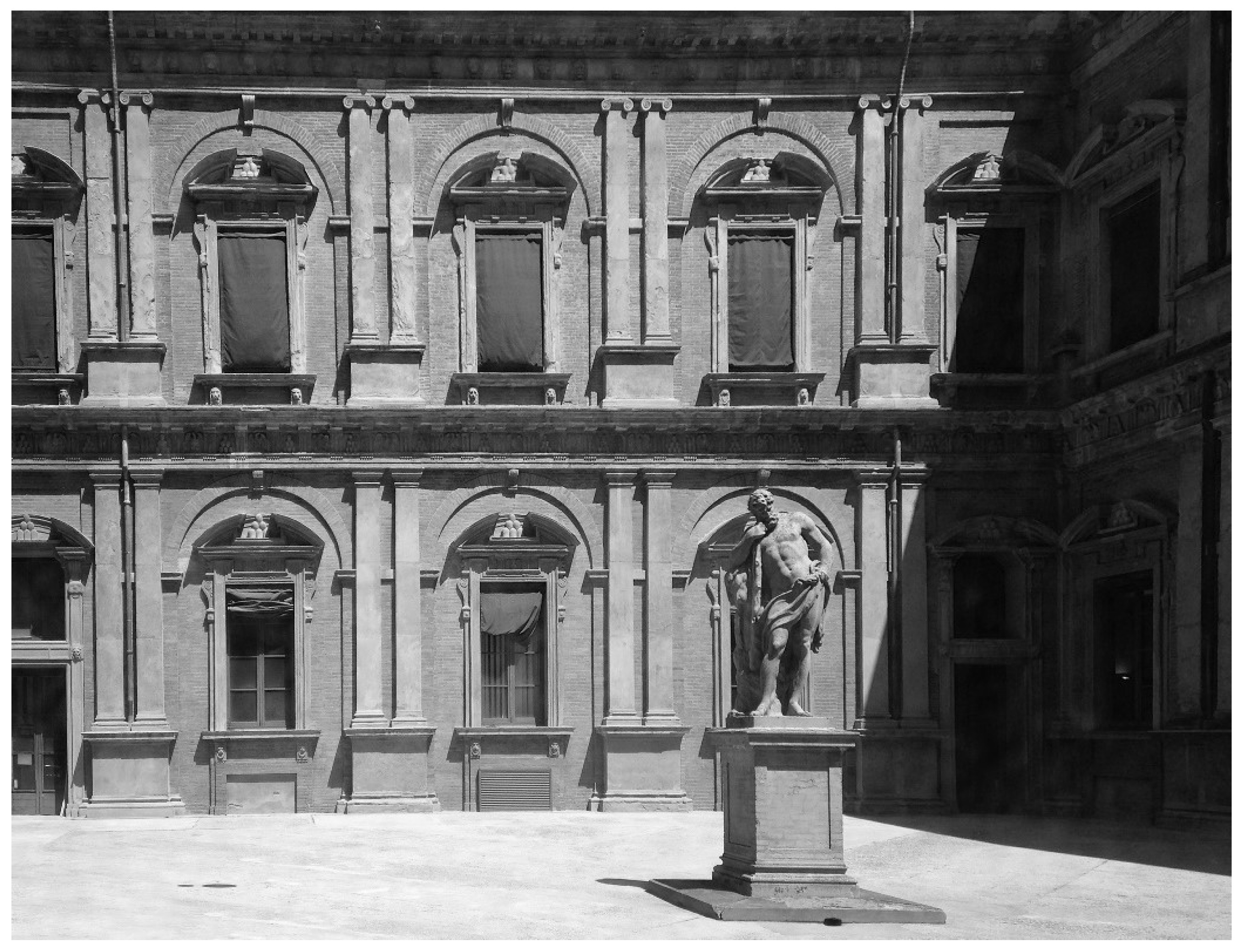
The study was developed as a complementary activity of the University research regarding the possible alternative uses of Corte d’Ercole (Hercules’ courtyard) (
Figure 3) of Palazzo Poggi (Bologna, in northern Italy), the main building of the University of Bologna hosting the rectorate and most of the institutional offices. The name of the courtyard is due to the statue of Hercules placed at its centre. This space is closed on the four sides by masonry walls, 0.70 m thick (U = 0.71 W/m
2K) with 10 variable wooden-framed windows (Uw = 5.8 W/m
2K, Uf = 2 W/m
2K, g = 0.85) for each of the façades.
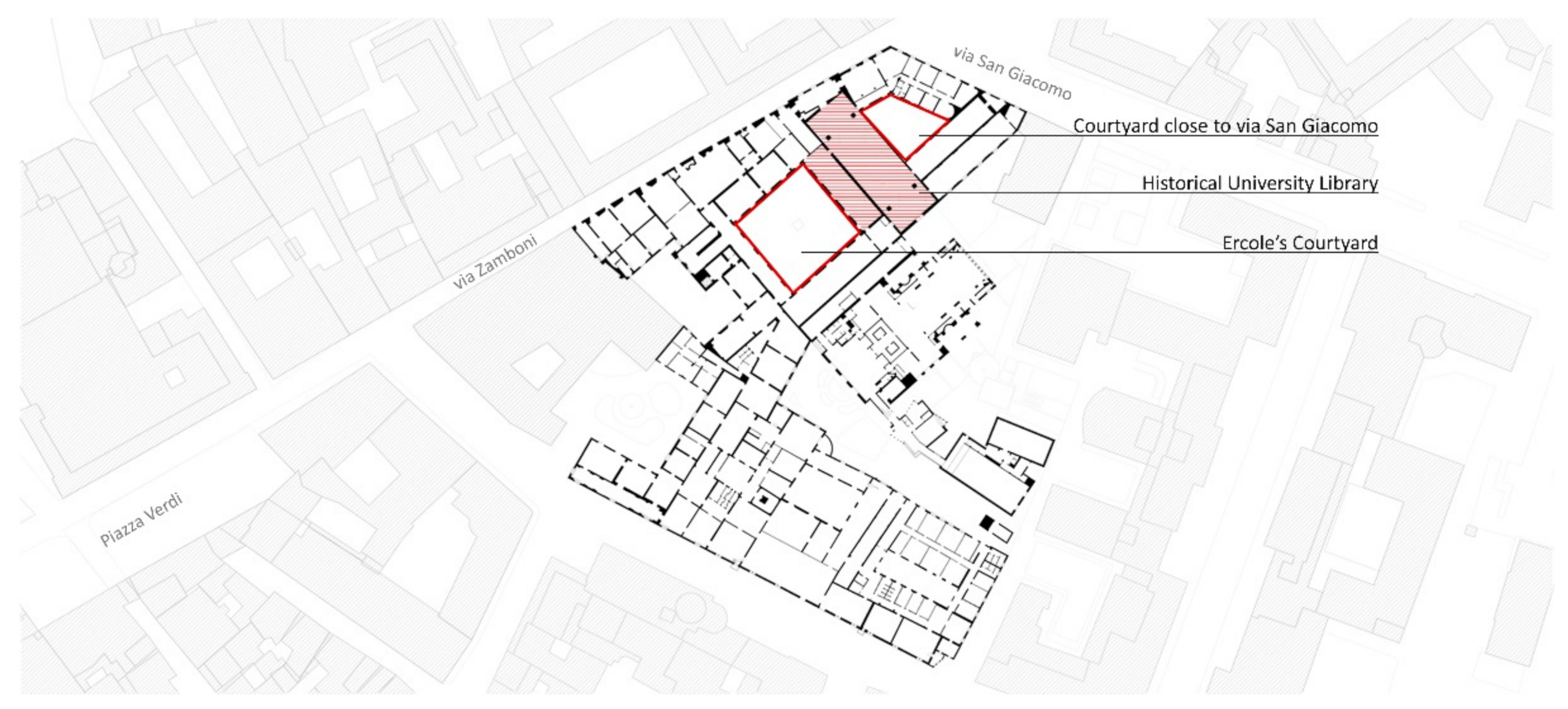
The building’s functions and several administrative offices are spread over two floors while around the court the most representative spaces are dedicated to the university museum, the lecture halls of the Department of History, Culture and Civilization. Additionally, the historic Aula Magna of the University Library stands along the north-east side of the court, overlooking the opposite side which faces a second courtyard on Via San Giacomo.
All these surrounding spaces (
Figure 4) play a relevant role in the proposed evaluation.
In order to obtain a large representative additional space for public use or exhibition purposes, a design solution to cover the courtyard has been explored several times without really achieving a convincing configuration. Despite the advantages offered by a completely reshaped circulation and by the additional activities (especially those involving the student population during institutional events) that may be hosted in the obtained space, the main concern was connected with the uncertainty about its environmental quality considering that no heating or cooling system would be installed. The variable climate condition on a daily and seasonal basis suggested carefully considering a permanent covered space. A movable system, based on a glazed surface supported by a metal structure, capable of adapting the space configuration over the year, was explored, however the structural loads on the surrounding walls were considered too relevant and the impact of the supporting elements not compliant with preservation requirements.
Thus, an alternative design option based on a lightweight metal structure with cables stiffening and a translucent/transparent membrane has been explored for the purpose of the present study. This innovative and lightweight solution allowed reduction of the impact on the surrounding walls and the adoption of a movable system to be envisaged for changing the configuration of the space during the warm summer period while benefitting from the greenhouse effect during winter.
Accordingly, three main use scenario are exanimated with the purpose of supporting the decision-making process and better address the design phase at early stage.
To evaluate the annual trend of the internal temperature in the courtyard, real data referred to internal and external temperature as well as solar irradiation were used. Input data on climatic conditions (Te and Ip) were obtained from the Regional Agency for Environmental Protection (ARPAE Emilia-Romagna) with reference to the year 2016. The probe HOBO RH/Temp (from ONSET COMPUTER) installed inside the historical library was not directly used for measuring the courtyard temperature, but to double check the reliability of input data regarding the building internal temperature.
3.3. Model Application
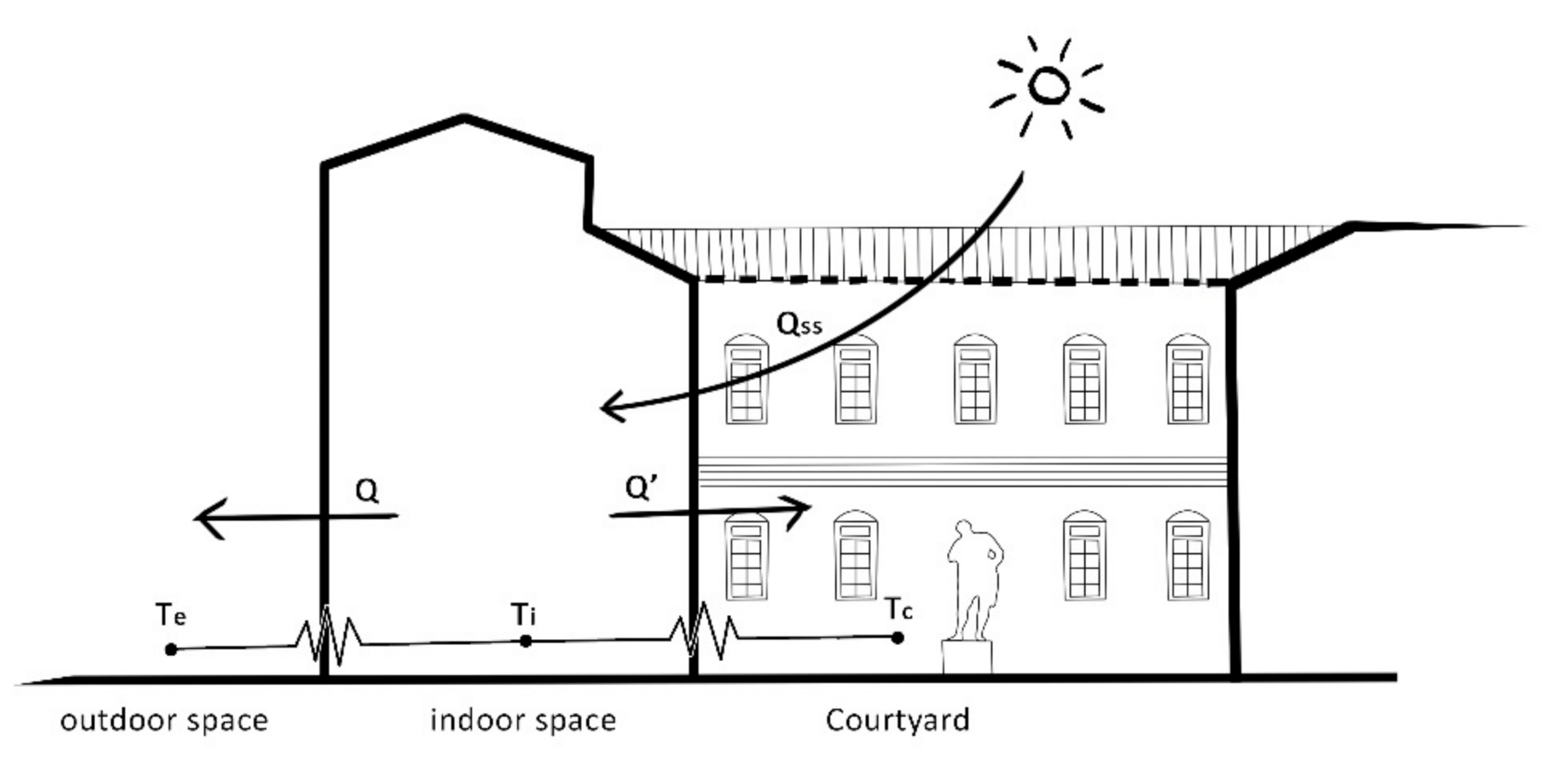
Figure 2 shows the theoretical model from ISO 13790 applied to the specific case study of Corte d’Ercole (Hercules’ courtyard) in Palazzo Poggi including the adjacent environments.
The external area is defined by the courtyard wing facing on via San Giacomo and Piazza Puntoni, which is characterized by four masonry façades (of different heights) 0.70 m thick. Related input data are: external air temperature (Te, °C) and solar radiation (Ip, W/m2).
The internal area (inside the buildings), includes some complementary spaces and the Aula Magna of the University Library of Bologna, whose temperature varies between 18 and 26 °C throughout the year. The main related input data is indoor air temperature (Ti, K).
The courtyard area is characterized by three classic façades with 10 openings and a fourth one with more openings. Related input data are: external air temperature (Te, °C) and solar radiation (Ip, W/m2).
The assumption is that the amount of heat transferred from inside to outside (
Q) is equal to the amount of heat exchanged between the inside and the courtyard (
Q’), as reported in Formula (1):
The covered courtyard is assimilated to a solar greenhouse, that’s why the solar thermal input (
Qss) entering through the hypothetical roof and reaching the interior of the building follow ISO 13790 [
19], which provides Formula (2) to determine the solar heat gains in the case of attached sunspace.
where
Qss is solar heat gains entering the conditioned space from the sunspace, measured in (MJ);
Qsd is the sum of direct heat gains through the partition wall, measured in (MJ);
Qsi is indirect heat gains, measured in (MJ).
In the case of Hercules’ courtyard, the
Qsi value is equal to 0 (zero), given that the indirect contributions during the summer regime do not significantly affect the energy exchanges due to solar radiation. For this reason, it is possible to rewrite Formula (2) as:
The direct solar heat gains
Qsd is defined as the sum of the thermal contributions transferred through the transparent (Subscript w) and opaque (Subscript p) surfaces of the wall partition.
Some terms of the formula (4) are variable and linked to the climatic data and/or the configuration choices of the roof, while others depend on the geometry and physical characteristics of Hercules’ courtyard and of the building.
Table 2 summarises Hercules’ courtyard specific data. The heat-transfer coefficients
Hp,tot and H
p,e, calculated according to ISO 13789 [
21] are reported in
Table 3,
Table 4 and
Table 5.
Ip and
t depend on the selected analysis to be performed: if the scope is to study the heat input variation in the different months,
t will be worth considering and consequently the values of the average monthly solar radiation must be entered.
If a more in-depth analysis is to be carried out on hourly basis,
t would become:
In accordance, hourly solar radiation values must be entered. To complete the calculation and obtain the
Qsd value,
F(sh,e), (1-
F(F,e)) and
ge referred to the roofing envelope and its shading must be entered. In the case a three-layer ETFE membrane cover is adopted, the outcome obtained on 01/01/2016 at 12.00, without any shading device is:
3.4. The System of Thermal Contributions
Formula (1) sets the amount of heat transferred from inside to outside (Q) equal to the amount of heat exchanged inside the courtyard (Q ‘). Developing the formula with relation to the geometric configuration of the covered courtyard, the following can be obtained:
By using Equations (5) and (6) in formula (1),
The temperature of the courtyard (T
c) is then explicitly obtained:
That is, by rearranging the terms of the equation:
Formula (7) allows us to obtain the internal temperature of the courtyard on hourly basis according to the steady-state model assumptions.
5. Dynamic Simulations and Validation
In order to assess the reliability of the simplified method’s application, the outcomes of the calculation process, based on the EN ISO 13790 algorithm and steady state assumptions, have to be compared with those obtained through a dynamic simulation. The simulation has been performed using DesignBuilder, which is a modelling environment commonly used to assess a range of environmental performances such as: energy consumption, carbon emissions, comfort conditions, daylight illuminance, maximum summertime temperatures and HVAC (Heating, Ventilation and Air Conditioning) component sizes. The software adopts EnergyPlus as calculation engine. According to the purpose of the present study, it was used to assess the temperature distribution in the Hercules’s courtyard and the effects produced by the design options.
5.1. Model and Results
The case study has been directly modelled within the software. A simplified geometry consistent with that adopted during the whole process was created and the characteristics of materials, components and windows were customised, avoiding use of the libraries integrated in the software, with the specific goal to use the same transmittance values of the simplified calculation. The software offers the chance to download and use local climate files and, coherently, data referred to Bologna (Bologna/Borgo Panig files) were used.
The model consists essentially of a number of thermal zones, including a specific thermal zone corresponding to Hercules’ courtyard. No type of plant was assigned to the court’s thermal zone and, as a consequence, the simulation was conducted in free-run mode.
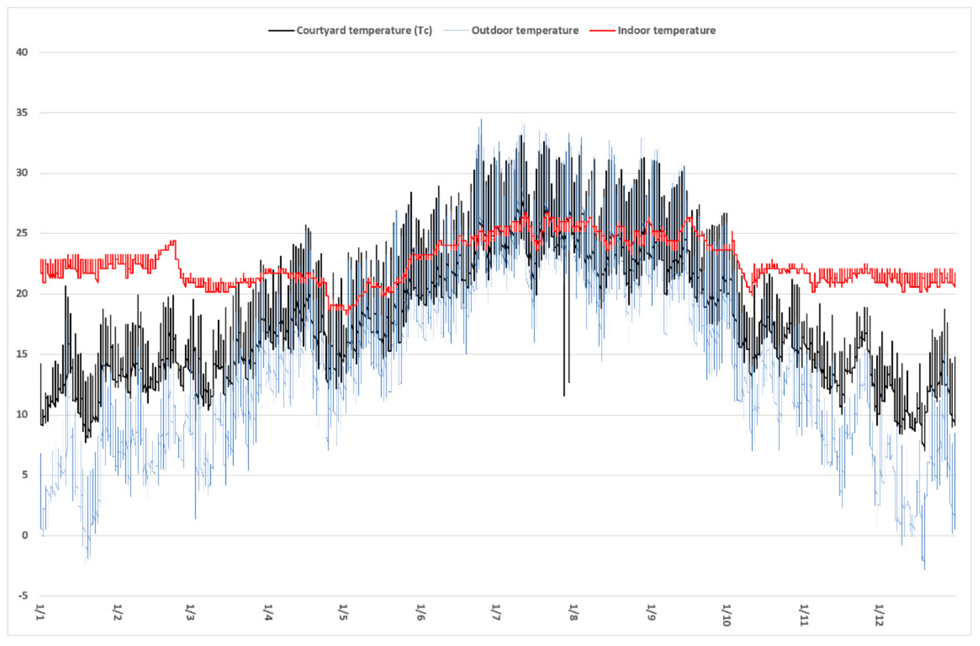
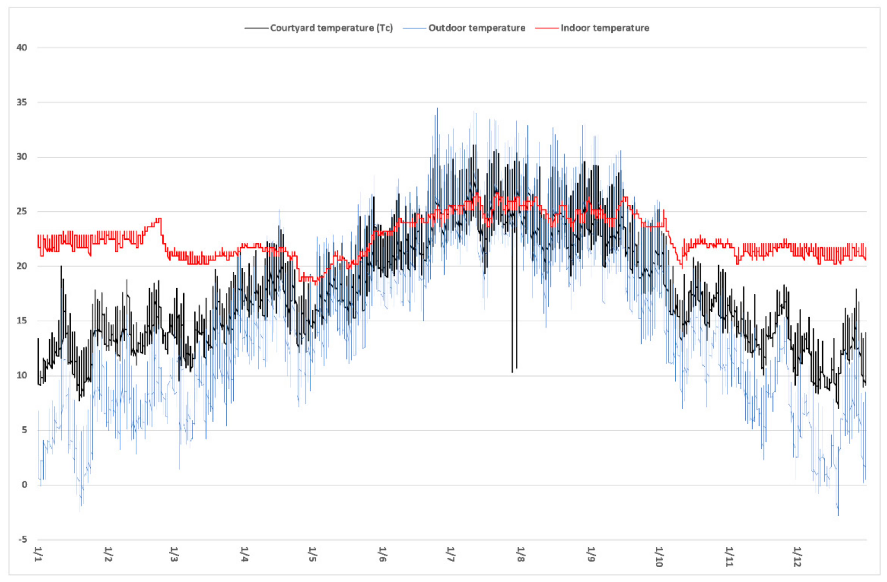
The simulations were carried out by selecting the results regarding environmental comfort and therefore the distribution of internal and external temperatures as main output according to the proposed technological options as
Figure 5 and
Figure 6 shows.
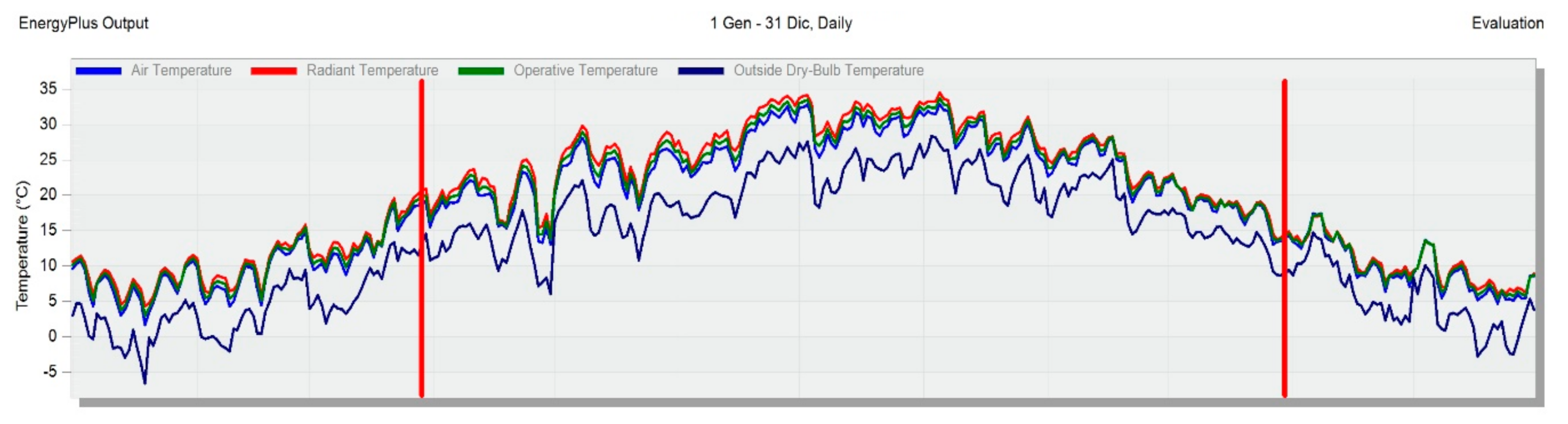
Figure 7 represents the temperature graph with reference to the thermal zone of the courtyard.
5.2. Comparative Discussion of Results
Examining
Figure 5 and
Figure 6, it clearly emerges that the design solution based on the use of the ETFE membrane ensures interesting results in terms of microclimate conditions supporting the ambition to convert the courtyards for additional functions. The daily thermal gradient ranges between 7 °C and 20 °C which can be considered quite a large variation; however, if observations are limited to the working hours it can be noted easily that this variation will significantly decrease. This means acceptable (when not suitable) conditions can be achieved without any cooling or heating system during spring, autumn and favourable winter days. In both cases, the algorithm reports an increase in the temperature of the court during the whole year that produces positive effects in terms of possible uses of the courtyard during the mentioned periods but suggests to install a movable covering in order to avoid unsuitable overheating effects during summer or to integrate the system with a shading device. As can be noted in
Figure 6, this option would provide quite good results.
The results of the simplified process based on EN ISO 13790 algorithm can be compared with those obtained by the dynamic simulations.
Figure 8 provides a comparative graphical representation between the temperature values of Hercules’s courtyard obtained from the two methods. Analysing the graph, it is possible to note that the daily temperature range obtained by DesignBuilder is slightly higher than that obtained by the simplified calculation based on ISO 13790. This is possibly due to the fact that the software uses actual climate data (instead of the 2016 dataset used for the simplified approach) and may overestimate solar radiation. Despite these differences, the dynamic simulations almost confirm the temperature trends.
5.3. Calibration and Validation of the Model
In order to determine the degree of confidence in the true value when using measurement procedures and/or calculations, the model validation followed the ASHRAE Guideline 14-2014 [
22,
23,
24], according to the hourly calibration method, and then comparing the main uncertainty indexes: mean bias error (MBE), root-mean-square deviation (CV(RMSE)) Pearson coefficient, normal mean bias error (NMBE).
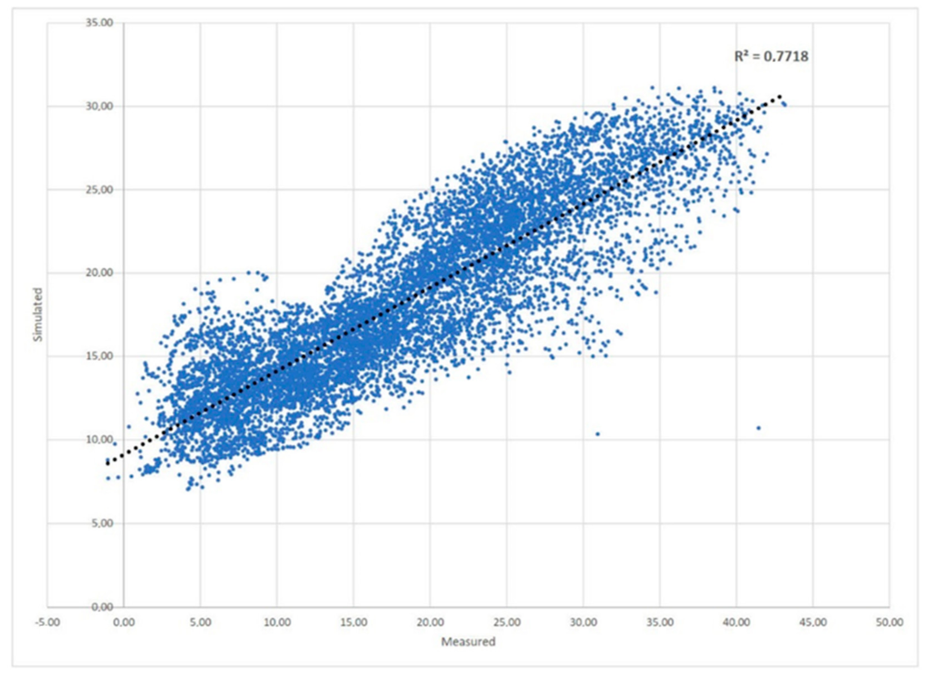
Table 8 reports the outcomes of the process with reference to each index and the calibration ranges defined by the guideline which states the acceptable limits with which to consider the model calibrated. Accordingly, a strong correlation is found with the resulting values. The proposed method can, therefore, be considered well calibrated, although
Figure 9 shows a scattered graph of the R
2 value for the regression mode.
The results of the calibration and validation process indicate that the simplified method enables to obtain accurate and acceptable results.
6. Conclusions
The results show that the calculation algorithm allows us to support the decision making process regarding both the choice of whether to install a covering on the courtyard and the selection of the most appropriate material to be used for the new roof. It can also support the definition of a management plan regarding the actuation of the movable covering according to the climate conditions of the use period. The effectiveness of the simplified approach is confirmed by the fact that changing the variables related to the correction factor due to the shading (Fsh,e) or to the solar factor (g) of the transparent covering element, the impacts on the temperature trends in the court (Tc) can be observed easily. This allows us to compare alternative materials and design options at early stage in a quite short time without investing the efforts and resources usually required to carry out the dynamic simulations of multiple configurations including shielding devices and/or movable roof options.
The described methodology tries to offer a quick and relatively easy to use tool for including the generated microclimate conditions when the opportunity to cover a courtyard is considered. Considering the state of the art, most of the cases this decision is driven by functional issues and the main technical concerns usually deal with structural configuration and calculation. Despite their relevance, these components do not fully represent the complexity of the design challenge in terms of creating comfortable spaces especially considering the evolving environmental conditions in dense urban fabric due to the effects of climate change.
The proposed algorithm allows us to evaluate and compare multiple technological solutions and several materials according to some pre-defined scenarios. Once the range of options has been reduced, the selected solutions require further exploration through a more detailed assessment process that carefully evaluates the dynamic behaviour with relation to the final architectural and technological configuration.
Considering the complex and interrelated phenomena frequently involving confined spaces like courtyards or atria, the constraints that often affect interventions on historical buildings, the risk of underestimating the effects of design decisions driven by architectural priorities on indoor environmental conditions, the chance to explore how different concepts may impact the efforts through formula (7) to undertake a simplified approach can be considered a valuable alternative to more complex and time-consuming detailed methods.
The proposed methodology has been developed within the wider research activity carried out at the Department of Architecture of the University of Bologna concerning optimised design strategies as tools to foster sustainability in architecture and to deliver energy efficient solutions also in the context of historical building stock. Within this framework, the capacity to quickly compare alternatives according to reliable and responsive methods for supporting the decision-making process is considered a priority for facing the complex challenges of the near future.


