Small Scale Experiments to Assess the Bearing Capacity of Footings on the Sloped Surface


Department of Civil and Environmental Engineering, University of Pittsburgh, Pittsburgh, PA 15213, USA
Eng 2020, 1(2), 240-248; https://0-doi-org.brum.beds.ac.uk/10.3390/eng1020016
Submission received: 10 October 2020
/
Revised: 16 November 2020
/
Accepted: 17 November 2020
/
Published: 20 November 2020
Abstract
:Construction of civil engineering structures on or next to a slope requires special attention to meet the bearing capacity requirements of soils. In this paper, to address such a challenge, we present laboratory-scale model tests to investigate the effect of footing shape on the sloped surface. The model comprised of a well stiffened mild steel box with three sides fixed and one side open. We considered both with and without reinforcement to assess the effectiveness of reinforcement on the sloped surface. Also, we used three types of footing (i.e., square, rectangular, and circular) to measure the footing shape effects. We considered three different slope angles to evaluate the impact of the sloped face corresponding to the applied load and the reinforcement application. We obtained that the maximum load carrying capacity in the square footing was higher than the rectangular and the circular footing for both the reinforced and the unreinforced soil. With the increase of geo-reinforcement in all three footing shapes and three sloped angles, the load carrying capacity increased. We also noticed a limiting condition in geo-reinforcement placement effectiveness. And we found that with the increase of slope, the load bearing capacity decreased. For a steep slope, the geo-reinforcement placement and the footing shape selection is crucial in achieving the external load sustainability, which we addressed herein.
1. Introduction
In the past, it was common to avoid civil engineering structures construction on a sloped surface due to the design and analysis complexities and associated time-dependent differential settlement. However, for the urbanization expansion and population increase, it is sometimes inevitable to consider the structure construction on or next to the inclined surface [1]. On the other hand, in geological locations where mountains dominate, the bearing capacity of the slope surface requires extra attention to avoid any failure of structure. Among others, bridge footing, towers for transmission and telecommunication, and retaining walls are also founded on sloped surfaces. The footing shape may be different (e.g., rectangular, circular, square, or any combination) considering the requirements of the structure. For the strip footing, Terzaghi [2] first presented the ultimate bearing capacity of soil considering the shear strength properties of soil. Later on, for different footing shapes, among others, Meyerhof [3]; Vesic [4]; de Buhan and Garnier [5]; Cerato and Lutenegger [6]; Gourvenec [7]; and Georgiadis [8] also proposed modification to the Terzaghi proposed method.
Construction of a structure on any sloped surface is relatively more challenging compared to a plain surface because of complex load distribution phenomena and subsequent responses. However, ground improvement methods using geo-reinforcement, development, and advancement of engineering technology added value to utilize problematic soil (Duncan et al. [9]). In this regard, it is essential to find out the bearing capacity of foundation on the sloped surface, which is the motivation of the present paper. Also, in the last few decades, a wide range of geo-reinforcement elements have been used to improve the bearing capacity of soils. Among others, Koerner [10] presented details design methods using geogrids, geonets, geomembranes, geosynthetic clay liners, geopipe, geofoam, and geocomposites. However, considering cost and effectiveness, availability of reinforcement, and design perspective, the application of geotextiles is popular over others [11]. Therefore, in our small-scale experiments, we also used geotextiles.
The bearing capacity of geomaterials at slope depends on many factors and can be summarized under five headings. They are the geometry of the sloped surface, loading condition, soil properties, footing properties, and reinforcement types. The first one also includes the height of slope, the normalized edge distance (i.e., the edge distance from slope/the footing width), planes’ weakness, and slope angle [8]. The loading condition includes vertical load or inclination of the applied load [12,13]. The foundation soil properties comprise of soil types, the cohesion, the angle of internal friction, the modulus of elasticity, the Poisson’s ratio, the permeability, and the relative density [6]. Also, footing shape, reinforcement types, properties, and spacing of the geo-reinforcement have a significant effect on the bearing capacity of the slope. However, there is little research where footing shapes are considered for a sloped surface considering the reinforced and the unreinforced soil for the identical test conditions varying slope angle, which we present herein through laboratory experiments.
2. Statement of the Problem
We present the problem statement in Figure 1. The study domain’s height and length are H and L, respectively. The width (W) is along the perpendicular direction of the paper (see also Figure 1b). We consider δ as the slope angle. We consider three faces are fixed, and one face is open (see also Figure 2a) so that we could investigate the slope failure for loading. We only consider the vertical load (P) without eccentricity. Also, we assume the length and the width of the rectangular footing are l and , respectively; while for the square and the circular footing w = l, dc = w = l, respectively, where dc represents the diameter of the circle. The ratio () of footing’s base and the distance between the edge of the slope or the boundary opposite to the open face is kept constant. In Figure 1, s is the spacing of the geotextile and d represents the depth of the geotextile from the base of the footing.
We assume that the soil mass is homogeneous and obey the Mohr-Coulomb criteria where parameters are the effective cohesion and the effective angle of internal friction . Also, in Figure 1, the specific weight is presented as . The soil mass will sustain the applied vertical load (P) as long as the porous media meets the equilibrium condition and the stress state along the outside of the footing boundary is in the limiting condition (see also Duncan et al. [9]).
Also, there are several theories for the failure mechanism of the sloped surface (see also Anderson and Richards [14]). We summarized these theories under two headings: failure mechanism due to the instability and failure mechanism due to the punching [5]. In this regard, Duncan et al. [9]) discussed a total of 13 case studies for slope failures and demonstrated possible reasons for the failure of each case. In this paper, we discuss failures of the sloped surface developed beneath the footing due to the punching and the geomaterials instability. In Appendix A, we present failure resistance mechanisms of reinforced soil.
Additionally, assuming , , , and H are constant (see Figure 1), if we equate the average shear stress along the slip surface to obtain the factor of safety, the slope angle is the critical criterion, which we present herein through the experimental results for both the reinforced and unreinforced soil.
In the next section, we discuss the properties of soil and geotextiles used for experiments.
3. Properties of Soil and Geotextiles
The soil used in our experiment was comprised of clay (12.0%), silt (52.0%), sand (34.0%) and gravel (2.0%). The liquid limit, the plastic limit, and the shrinkage limit of the soil are 52.0%, 26.0%, and 23.0%, respectively. The effective cohesion and the effective angle of internal friction are 5 kPa and 330, respectively. The specific gravity of the soil is 2.61. We performed sieving and the hydrometer test for the grain size distribution of the soil. We determined the Atterberg limit test using a semi-automatic cone penetrometer. We obtained the shear strength parameter using the direct shear test machine. For all laboratory experiments, we followed the American Society for Testing and Materials (ASTM) standards.
Additionally, the geotextiles used in the experiments were multifilament woven geotextiles. From laboratory tests, we also obtained the geotextiles’ thickness, weight, the maximum extension, the tensile strength, the California Bearing Ratio (CBR) punching, and the vertical permeability (see also Koerner [10] and Koerner [11]). We present the details of geotextiles properties in Table 1.
4. Experimental Methods
We developed a rectangular box made of mild steel for laboratory experiments to assess the bearing capacity of footings on the sloped surface. The dimensions of the box were W = 45.72 cm × D = 45.72 cm × L = 60.96 cm, where W = width, H = height, and L = length (see also Figure 2a). The three faces of the box were closed, and one side was open. We used grooves and screw along the length and width of the box so that the developed pressure in the experimental setup would not cause failure. We applied medium viscosity oil in the inner surface of the box to minimize the sidewall effect. Also, we prepared three mild steel footings of equal thickness (i.e., square, rectangular, and circular) to investigate the footing shape effects.
As part of the sample preparation, we first oven-dried soil samples and sieved. Then, we determined the grain size distribution and physical properties. Throughout the testing, we kept the optimum moisture content constant. Also, during the tests, we kept an identical distance from the edge of the slope and footing, the spacing of the geotextiles, and the distance from the footing base to avoid their effects. We maintained three slope angles to evaluate the slope angle effects. These angles were 35°, 40°, and 45°. Additionally, to keep the uniformity of the compaction of the soil in the mild steel box, we compacted the soil layer by layer. Then, we used identical pocket penetrometer reading during the sample preparation. We placed a geotextile at a uniform depth, and we used similar geotextiles to maintain their properties constant. In this regard, for geotextile placement, we followed Koerner [10] and Koerner [11]. Also, we kept the size and thickness of the geotextile constant to avoid their effects (see also Islam et al. [15]).
We used the Universal Testing Machine (UTM) with an electric load cell (see Figure 2b) to apply load through the footings. We applied load at the centroid of the footing to avoid the loading angle effect and the eccentricity influence. We also used a data logger to measure the settlement. We recorded the load every 0.5 mm deformation interval until the sloped surface failed.
5. Results and Discussions
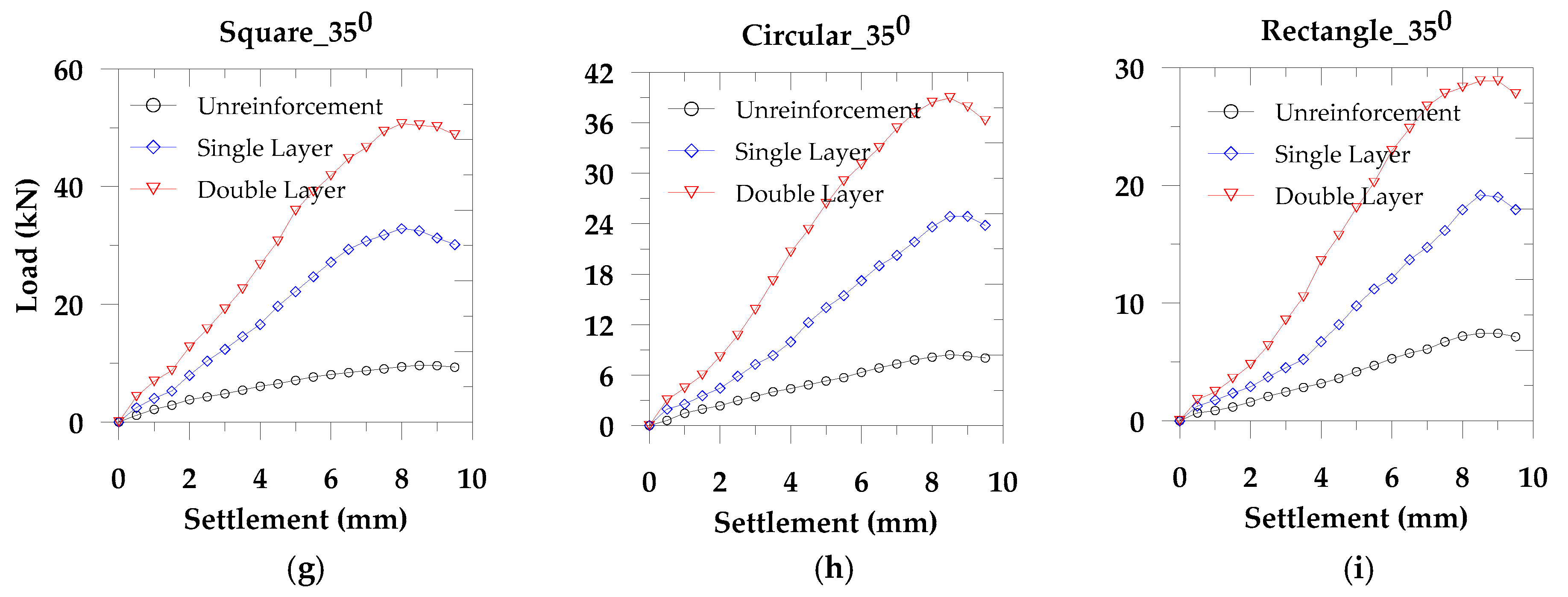
We considered three types of footing (square, rectangular, and circular) for slope angles 35°, 40°, and 45° to study the effect of footing shape and the slope angle. We performed these tests on both the unreinforced and reinforced soil. Also, to evaluate the reinforcement effect, we considered single and double layer geotextiles, maintaining a uniform distance throughout the tests. From Figure 3, we observe that the load carrying capacity in the square footing is higher compared to the circular and the rectangular footing shape. The square footing develops the low mean stress compared to the other two shapes of footings and results in the high operative frictional angles. Therefore, the load carrying capacity in the square footing is high for the equivalent longest dimension in the rectangular footing and the equivalent diameter of the circular footing. This stress dependency on the footing shape is related to the critical state strength [16]. Also, Michalowski [17] reported that with the increase of footing aspect ratio, the bearing capacity factor also increased (see also Salgado et al. [18]; Gourvenec [13]). Moreover, Cerato and Lutenegger [6] presented that the bearing capacity in the square footing is higher than the circular footing. However, in the previous study of the footing shape effect, the combined influence of the slope angle and the reinforcement were ignored, which we addressed in this paper through laboratory experiments. From Figure 3, we also find that with the increase of slope angle, the load carrying capacity decreases, which supports Georgiadis [8].
During the application of load to the footing, load transfers through particles of the soil mass. In response to loads, particles may break or dislocate due to the slip action along the sliding plane, resulting in the instabilities of soil grains. We could explain such behavior using the micromechanics of particles (see Islam et al. [19]). For the unreinforced soil mass, if the load bearing capacity exceeds the limiting criteria, the porous media may fail [9]. However, we could minimize such an instability using geotextiles, which increase the strength properties of the porous media (see Koerner [10]). Also, geotextiles resist the punching failure beneath the footing and reduce the effect of circular or non-circular slip surface by increasing the factor of safety on the sloped surface. On the other hand, mathematically, the area ratio of footings for square, circular, and rectangular in this paper are present as , which also impact in the maximum load bearing capacity due to the surface area.
In Figure 4, we present the reinforcement effect for each sloped surface and each footing shape. In addition, in Figure 5, we present the maximum load bearing capacity for each footing. We observe that with the increase of reinforcement, the maximum load bearing capacity also increases. However, the maximum load carrying capacity decreases with the rise in the slope angle. We also notice that the average maximum load carrying capacity in the square footing for the unreinforced soil and 35° slope surface are 14.11% and 29.48% higher compared to the circular footing and the rectangular footing, respectively. However, these values for the single layer geotextile are 32.01% and 71.26%, respectively, while for the double layer geotextile, identical values are 34.15% and 75.57%, respectively. Also, from Figure 5, we observe that the percentile values mentioned above decrease with the increase of slope angle. Comparing the square footing results for 35° slope surface with identical conditions and the other two footings, we find that the changes in the ultimate load carrying capacity in the single layer and double layer geotextile are 2.14% and 4.31%. These results demonstrate an optimum geotextile placement layer for a specific soil deposit with the sloped surface, which is essential in finding an economic ground improvement method.
6. Conclusions
We presented the sloped surface load carrying capacity comparing the reinforced and the unreinforced soil considering three footing shape and three slope angles. We found that the square footing provided higher resistance than the circular and the rectangular footing. Also, for all three footing shapes, the load bearing capacity decreased with an increase in the slope angle. In contrast, the resistance in soil increased with the reinforcement application by minimizing the punching failure and the instability of geomaterial.
For any specific soil deposit with a sloped surface, it is critical to select the footing shape to achieve the maximum benefit to sustain the external loading on the footing. Considering the foundation and the loading condition, a ground improvement system through the geo-reinforcement application can be introduced. However, we also observed limiting criteria from our experimental evidence for a specific slope, the geo-reinforcement, and the footing shape. After the limiting condition, the percentile increase in the ultimate bearing capacity for the geotextile is negligible.
Funding
This research received no external funding.
Acknowledgments
The author acknowledges the laboratory technician in preparing the experimental setup.
Conflicts of Interest
The author declares no conflict of interest.
Appendix A
Failure Mechanisms of Reinforced Soil
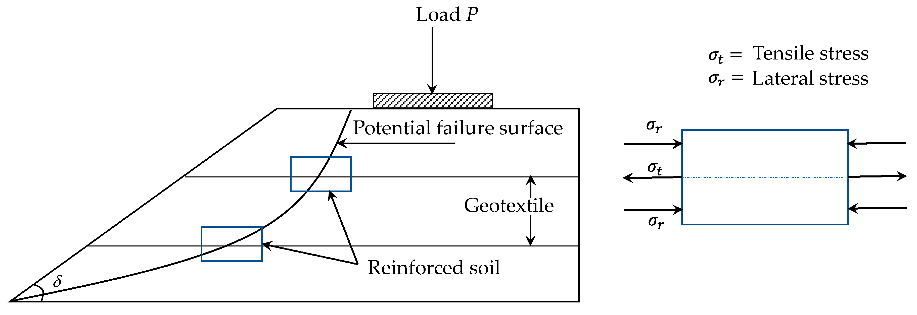
Application of geotextile functions as a reinforcement which provides resistance to the tension by inducing the stress state [20]. Also, geotextiles support the planar load and the normal load. Thereby, geotextiles increase the stability of sloped surface. In this regard, among others, Shukla [20] demonstrated detailed failure mechanisms of reinforced soil. In Figure 2, we present the basic mechanisms of reinforced soil.
Figure A1.
Schematic failure resistance mechanism in reinforced soil.

References
- Han, J. Principles and Practices of Ground Improvement; Wiley: Hoboken, NJ, USA, 2015. [Google Scholar]
- Terzaghi, K. Theoretical Soil Mechanics; John Wiley and Sons: New York, NY, USA, 1943. [Google Scholar]
- Meyerhof, G.G. The ultimate bearing capacity of foundation on slopes. In Proceedings of the 4th International Conference on Soil Mechanics and Foundation Engineering, London, UK, 12–24 August 1957; pp. 384–386. [Google Scholar]
- Vesic, A.S. Bearing capacity of shallow foundations. In Foundation Engineering Handbook; Winterkorn, H.F., Fang, H.-Y., Eds.; VanNostrand Reinhold Company: New York, NY, USA, 1975; pp. 121–147. [Google Scholar]
- De Buhan, P.; Garnier, D. Three Dimensional Bearing Capacity Analysis of a Foundation near a Slope. Soils Found. 1998, 38, 153–163. [Google Scholar] [CrossRef] [Green Version]
- Cerato, A.B.; Lutenegger, A.J. Bearing Capacity of Square and Circular Footings on a Finite Layer of Granular Soil Underlain by a Rigid Base. J. Geotech. Geoenviron. Eng. 2006, 132, 1496–1501. [Google Scholar] [CrossRef]
- Gourvenec, S. Shape effects on the capacity of rectangular footings under general loading. Géotechnique 2007, 57, 637–646. [Google Scholar] [CrossRef]
- Georgiadis, K. Undrained Bearing Capacity of Strip Footings on Slopes. J. Geotech. Geoenviron. Eng. 2010, 136, 677–685. [Google Scholar] [CrossRef]
- Duncan, J.M.; Wright, S.G.; Brandon, T.L. Soil Strength and Slope Stability; John Wiley & Sons: Hoboken, NJ, USA, 2014. [Google Scholar]
- Koerner, R.M. Designing with Geosynthetics, 5th ed.; Prentice Hall: Upper Saddle River, NJ, USA, 2005. [Google Scholar]
- Koerner, R.M. Geotextiles: From Design to Applications; Woodhead Publishing: New York, NY, USA, 2016. [Google Scholar]
- Georgiadis, K. The influence of load inclination on the undrained bearing capacity of strip footings on slopes. Comput. Geotech. 2010, 37, 311–322. [Google Scholar] [CrossRef]
- Gourvenec, S.; Randolph, M.; Kingsnorth, O. Undrained Bearing Capacity of Square and Rectangular Footings. Int. J. Geomech. 2006, 6, 147–157. [Google Scholar] [CrossRef]
- Anderson, M.G.; Richards, K.S. Slope Stability: Geotechnical Engineering and Geomorphology; John Wiley & Sons: Chichester, UK, 1987. [Google Scholar]
- Islam, M.N.; Ali, M.M.Y.; Serker, N.H.M.K.; Siddika, A.; Mofiz, S.A. Improvement of Bearing Capacity of Soil at Slope: Comparison between Geojutes and Geotextiles. In Proceedings of the 17th Southeast Asian Geotechnical Conference, Taipei, Taiwan, 10–13 May 2010. [Google Scholar]
- Schofield, A.N.; Wroth, P. Critical State Soil Mechanics; McGrawHill: London, UK, 1968. [Google Scholar]
- Michalowski, R.L. Upper-bound load estimates on square and rectangular footings. Géotechnique 2001, 51, 787–798. [Google Scholar] [CrossRef]
- Salgado, R.; Lyamin, A.V.; Sloan, S.W.; Yu, H.S. Two- and three-dimensional bearing capacity of foundations in clay. Géotechnique 2004, 54, 297–306. [Google Scholar] [CrossRef]
- Islam, M.N.; Siddika, A.; Hossain, M.B.; Rahman, A.; Asad, M.A. Effect of Particle Size on the Shear Strength Behavior of Granular Materials. J. Aust. Geomech. 2011, 46, 75–86. [Google Scholar]
- Shukla, S.K. An Introduction to Geosynthetic Engineering; Taylor & Francis: Chennai, India, 2016. [Google Scholar]
Figure 1.
Schematic diagram of a shallow footing near slope. (a) Side view and (b) cross-section along the footing.
Figure 1.
Schematic diagram of a shallow footing near slope. (a) Side view and (b) cross-section along the footing.

Figure 2.
Schematic diagram of (a) the experimental setup and (b) the loading arrangement.

Figure 3.
Effect of footing shape: (a–c) unreinforced soil, (d–f) single layer geotextile reinforced soil, and (g–i) double layer geotextile reinforced soil.
Figure 3.
Effect of footing shape: (a–c) unreinforced soil, (d–f) single layer geotextile reinforced soil, and (g–i) double layer geotextile reinforced soil.

Figure 4.
Effect of geotextile reinforcement and footing shape: (a–c) for 45°; (d–f) for 40°; and (g–i) for 35° sloped surfaces.
Figure 4.
Effect of geotextile reinforcement and footing shape: (a–c) for 45°; (d–f) for 40°; and (g–i) for 35° sloped surfaces.


Figure 5.
Maximum load carrying capacity: (a) unreinforced soil, (b) single layer geotextile, and (c) double layer geotextile.
Figure 5.
Maximum load carrying capacity: (a) unreinforced soil, (b) single layer geotextile, and (c) double layer geotextile.


Table 1.
Properties of geotextiles.
| Property | Unit | Values | |
|---|---|---|---|
| Type | - | Multifilament Woven | |
| Thickness | mm | 1.90 | |
| Weight | gm/m2 | 245.0 | |
| Maximum Extension | Strip Method | % | 16.75 |
| Grab Method | % | 35.43 | |
| Tensile Strength | Strip Method | kN/m | 7.61 |
| Grab Method | kN/m | 28.65 | |
| CBR Punching | kN | 1.89 | |
| Vertical Permeability | m/sec | 1.85 × 10⁻⁶ | |
| Note: CBR = California Bearing Ratio | |||
Publisher’s Note: MDPI stays neutral with regard to jurisdictional claims in published maps and institutional affiliations. |
© 2020 by the author. Licensee MDPI, Basel, Switzerland. This article is an open access article distributed under the terms and conditions of the Creative Commons Attribution (CC BY) license (http://creativecommons.org/licenses/by/4.0/).
Share and Cite
MDPI and ACS Style
Islam, M.N. Small Scale Experiments to Assess the Bearing Capacity of Footings on the Sloped Surface. Eng 2020, 1, 240-248. https://0-doi-org.brum.beds.ac.uk/10.3390/eng1020016
AMA Style
Islam MN. Small Scale Experiments to Assess the Bearing Capacity of Footings on the Sloped Surface. Eng. 2020; 1(2):240-248. https://0-doi-org.brum.beds.ac.uk/10.3390/eng1020016
Chicago/Turabian StyleIslam, Mohammad Nurul. 2020. "Small Scale Experiments to Assess the Bearing Capacity of Footings on the Sloped Surface" Eng 1, no. 2: 240-248. https://0-doi-org.brum.beds.ac.uk/10.3390/eng1020016