
Piezoresistive Sensing Approaches for Structural Health Monitoring of Polymer Composites—A Review


Materials Science & Engineering Department, Institute of Space Technology, Islamabad 44000, Pakistan
Eng 2021, 2(2), 197-226; https://0-doi-org.brum.beds.ac.uk/10.3390/eng2020013
Submission received: 14 April 2021
/
Revised: 18 May 2021
/
Accepted: 19 May 2021
/
Published: 22 May 2021
(This article belongs to the Special Issue Stylistic Design Engineering (SDE))
Abstract
:Structural health monitoring (SHM) is an emerging paradigm of real-time in situ structural evaluation for the detection of damage and structural degradation. This is achieved while the structure is kept in-service as against traditional non-destructive evaluation (NDE) techniques which require scheduled interventions while the structure is kept offline. SHM offers great advantages over traditional regimens of condition monitoring (CM) by improving structural reliability and safety through timely detection of structural defects also known as “diagnosis”. Polymeric composite materials offer the unique opportunity of integrating different phases for designing self-sensing smart systems capable of self-diagnosis. Polymers are unique in the sense that they can be designed in various configurations as they generally have facile manufacturing procedures. Among other properties, piezoresistance is the one that can be detected in composites in real-time as a function of strain. Conductive polymers including intrinsic and extrinsic conductive polymers can be used to induce piezoresistivity in composites. Careful design procedures can be adopted to maximize the sensitivity of these piezoresistive composites in order to fully exploit the potential of this property for SHM. Various manufacturing/integration strategies can be employed to effectively use piezoresistance in composites for structural health monitoring. These include self-sensing in carbon fiber-reinforced composites, use of surface deposited/mounted sensing films and patterns, integration of filaments and yarns during reinforcement manufacturing or lay-up and impregnation of reinforcements with piezoresistive matrices. A comprehensive review of these techniques is presented with the view of their utility in the SHM of composites. A selection criterion for these techniques is also presented based on sensitivity, manufacturing method and detection capability.
1. Introduction
Composites are defined as multiphase materials with certain complementarity in their properties arising from the synergistic effect of their constituents on one another. Most of the composites comprise of two phases with one phase providing the functional properties (the reinforcing phase) and the other one providing the first phase with the shape and certain structural integrity termed as the matrix phase. Reinforcements can be added to “complement” various properties of matrices. These include mechanical properties such as strength, stiffness, elongation at break, toughness and hardness in addition to electrical and thermal conductivity, etc. Due to this design flexibility arising from the freedom that the vast array of available materials provides in the selection of various structure–property relationships, composites have found wide applications in various domains such as aeronautics, transportation, industrial and civil infrastructure, etc., as well as a tremendous research interest.
Smart composites are a special class of composites where one of the two phases (reinforcement or matrix) endows the composite with an added functionality. Sometimes these functional properties can be achieved by adding a third phase or “filler” material into the composite. The added functionality can be in the form of either sensing or actuation ability. The former comprises the ability to sense various environmental stimuli such as temperature, humidity and pressure, etc. This sensing ability can also include the ability to sense strain and monitor stresses, vibrations and thermal flux. These attributes can potentially make a composite sensitive to its own state of structural integrity or “health”. Actuation, on the other hand, is the ability to respond to various input stimuli and convert these into mechanical motion. Many forms of actuation mechanisms in composites include those which are either triggered by the physical stimuli such as temperature, light intensity, magnetic and electric field or by the chemical stimuli such as electrolyte concentration or pH.
Those smart composites which demonstrate actuation in response to changes in temperature undergo phase transformations in response to temperature changes (thermoresponsive). The phase change is usually accompanied by volume changes [1]. These changes in volume can be used to actuate mechanical motion in composites [2]. Jin et al. have reported phase change hybrids (PCHs) consisting of paraffin waxes deposited onto poly(diphenylacetylene) PDPA films [3]. It was reported that the PCH films demonstrate highly reversible thermomechanical actuation owing to phase transition in paraffin waxes.
Magneto responsive polymers are yet another class of smart composites [4]. An interesting application concerning the development of magneto responsive composites comprises flexible polymers and elastomers with distributed magnetic particles such as Magnetite, Fe3O4 [5]. The forces on the particles are transferred to the polymer resulting in locomotion and deformation [6]. As a result, shape distortion appears and disappears instantly when the external magnetic field is applied and altered. The combination of elastic and magnetic properties results in not only actuation but also in tunable elastic modulus with short response times. In one such application, the suspended magnetic particles were oriented under the effect of an external magnetic field [7]. The particles orient themselves along the magnetic dipoles resulting in a pearl chain structure once the surrounding matrix is cross-linked. Such composites exhibit structural anisotropy in their elastic response as well as anisotropic swelling characteristics in the presence of an external magnetic field [8].
Ionic polymer-metal composites (IPMCs) are known to demonstrate artificial muscle behavior under the influence of an applied voltage [9]. In IPMCs ion-exchange polymers such as Nafion or Flemion are sandwiched with metallic electrodes deposited using an electroless plating process [10,11,12]. The perfluorinated ionomers with ionic side groups allow ions to be transported through the membranes [13]. In one such application, water molecules were used to couple with cations in the polymer [14]. In the absence of electric potential, water/cation pairs are uniformly arranged inside the membrane. When the voltage is applied, the pairs redistribute to balance the charge resulting in the negative side swelling more than the positive side. In non-symmetric configurations, the imposed voltages can be used to generate twisting, rolling, twirling, whirling and non-symmetric bending [15]. This peculiar actuation mechanism has been used to design artificial muscles for robotic applications [16,17,18].
Yet another type of actuation mechanism has been reported in dielectric electroactive polymers (EAPs) [19] and their nanocomposites [20]. An EAP is effectively a composite with a lightweight polymer membrane sandwiched as a dielectric between two compliant electrodes. When an electric field is applied across the electrodes, the dielectric polymer contracts in the thickness direction thereby expanding in the planar direction due to the electrostatic forces at the two electrodes [21]. This actuation has been exploited in asymmetric configurations in order to achieve bending actuation not only for gripping as in robotic fingers [22] but also for locomotion [23].
Application of an electric field across the boundaries of a piezoelectric material can produce mechanical stress and vice versa [24,25,26]. Piezoelectric composites can be made by incorporating piezoelectric ceramics in a polymer matrix [27]. The compliant polymers offer superior flexibility whereas exceptionally high electromechanical coupling of piezoelectric ceramics gives them mechanical actuation and energy harvesting properties [28]. These piezoelectric composites are designed in so-called 1–3 or 0–3 configurations [29]. The 1–3 piezocomposites consist of piezoelectric pillars embedded in the polymer matrix. Dice-and-fill and Arrange-and-fill are two techniques that are used to make this type of composites. The 0–3 piezocomposites are relatively simpler and inexpensive to synthesize as inorganic piezoceramic particles are mixed in the polymer before it is cured. Both types of piezoelectric composites especially the 0–3 types have been used to fabricate MEMS [30] and macroscale devices for energy harvesting and actuation applications [31].
Another mode of actuation can be achieved in shape memory polymers and their composites. Composites with multiple phases where one of these, usually the fillers or fibers, acts as the fixity phase, thereby memorizing the initial polymer configuration and the other one as the switch phase, responsible for fixing the temporary shape, can be designed to have “memory” [32]. In addition to this, the introduction of reinforcements can significantly improve the mechanical properties of the polymer matrix having an intrinsic shape memory effect [33].
Self-healing composites are also categorized among smart composites since they have the ability to recover some of their mechanical properties once the healing cycle is allowed to proceed either with or without the intervention of some external trigger [34]. In the former case, they may be termed as non-autonomous self-healing systems requiring heat or UV light for healing to take place. The latter class of self-healing composites is fully autonomous in that the damage acts as the trigger for the healing mechanism to proceed. The first generation of autonomic self-healing composites comprises microspheres embedded in the composite matrix dispersed with the catalyst for initiation of the healing reaction [35]. Propagating cracks fracture the microsphere shell wall, releasing the healing agent which comes in contact with the dispersed catalyst. The catalyst initiates the curing reaction, thereby arresting the crack propagation. Most of the microspheres use DCPD (dicyclopentadiene) as the healing agent with first-generation Grubb’s catalyst [36]. DCPD undergoes ring-opening polymerization, heals relatively quickly in the presence of Grubb’s catalyst and shows minimal contraction upon crosslinking; some of the properties most desirable for a healing agent. An important drawback of using microspheres is that the microspheres can only release the healing agent once and there is no way of replenishing the healing agent. This has prompted the development of microvascular networks for self-healing composites [37]. Inspired from the vascular networks in living organisms, these vascular networks are filled with the resin and its curing agent (for two-part curing systems), once the crack damages the vascular network, the healing agent and its catalyst is filled up in the crack plane where it crosslinks and arrests the propagating crack [38]. The vascular networks can resupply the curing agent to the same crack plane in case of propagation of a crack in the same plane owing to capillary action. Earlier microvascular networks comprised of two sets of hollow glass fibers; one filled with epoxy resin and the other set with the curing agent as reported by Pang et al. [39]. Flexural loading tests demonstrated the utility of this approach as 97% of flexural strength was reported to have been recovered after healing. Norris et al. additionally added UV-sensitive dyes for damage identification and subsequent observation of healing mechanism [40]. Other researchers have developed microvascular networks by incorporating sacrificial fibers, subsequently heating and evaporating them to obtain micro-channels which were then filled with the healing agents [41]. Over the years the concepts have evolved into coaxially spun nanofibers with resin and hardener systems [42]. These coaxially spun nanofiber mats can be incorporated inside a composite to introduce self-healing capability. Three-dimensional printed sacrificial scaffolds made of 60 wt.% petroleum jelly and 40 wt.% microcrystalline wax have also been reported albeit with an obvious disadvantage related to difficulty in removing melted sacrificial molds as some viscous liquid always gets locked inside the vessels [43].
Completely autonomic self-healing has been reported for certain ionomers and their composites. In these materials, the self-healing mechanism is activated during high energy impact by the synergistic effect of damage on the self-healing materials [44]. In one such study, Surlyn® which is a copolymer of ethylene and methacrylic acid was used as a matrix material with carbon fibers as a reinforcing material and heating element due to their excellent thermal transport properties [45]. The carbon fibers helped in resistive heating of the matrix to melt and heal it locally. The healing approach was tested in a medium velocity impact scenario. It was reported that the healing approach could achieve width–heal ratios of more than 0.9 under optimum heating conditions exhibiting complete recovery.
Self-sensing composites are another class of smart composites that are being developed in the broader framework of Structural Health Monitoring (SHM). SHM is a paradigm that is developed separately and involves the use of multidisciplinary approaches for on-line in-situ observation of structural integrity in real-time [46]. The older paradigm of condition monitoring (CM) whereby a structure is put off line or out of service and is monitored using various NDT techniques for scheduled maintenance has given way to a smarter and more cost-efficient paradigm of SHM where human intervention is also minimized owing to greater automation involved [47]. SHM also improves structural safety and operational reliability over traditional inspection methods as the latter do not provide any information regarding the events which occur between two successive interventions [48].
SHM gets its inspiration from living bodies where a network of sensors sends continuous feeds of information about the state of the body’s health as a result of its interaction with the environmental parameters and various stimuli [49,50]. These signals are sent to the central nervous system via neural networks where the brain monitors and analyzes this information for further action in the form of actuation. An ideal SHM system should incorporate all of these elements of a living body [50]. The current focus of research is thus directed towards the development of such a holistic approach towards SHM by making a structure smart. A smart structure is able to interact with its environment by acquiring information about itself and its environment including the loading conditions. This not only results in greater reliability and safety but also helps develop operational history from the real-time data acquired from the suites of sensors. This history can in turn be employed to improve the structural design parameters. In its basic form SHM system comprises a network of sensors acquiring real-time information about the structural integrity and sending it to a centrally located computer via a data logging device [51]. Diagnostic algorithms can be developed to identify and distinguish electrical signals as depicting damage or safe operations. Additionally, prognostic algorithms can help predict the residual life of the structure on the basis of the diagnostic analysis [52]. Owing to its nature, any SHM system is multidisciplinary in its scope and execution.
Sensors are an important part of any SHM system. Various types of sensors may be incorporated in a monitoring system depending on the service conditions and phenomena which are intended to be monitored. The selection of suitable sensors is also dependent upon the nature of the structure including its mechanical and material properties. Since the SHM paradigm is intended to be implemented in critical applications where structural integrity and safety concerns outweigh the cost and complexity associated with the implementation of the SHM system, it is usually applied in civil and aeronautical domains. Critical civil structures such as bridges can thus have accelerometers and pressure sensors installed for monitoring vibrations and loading due to traffic. In aircraft, monitoring of strains is much more critical therefore these can be fitted with strain gauges. Traditional resin bonded metal foil strain gauges and Fiber Bragg Grating (FBG) sensors are commonly applied for this purpose. More recently diverse piezoresistive sensors have also emerged as a potential solution to the monitoring needs in aircraft owing to their superior sensitivity and adaptability. These sensors are usually applied as external sensing elements or as integrated sensors in various configurations during the manufacturing of the aircraft components.
2. Piezoresistance in Polymers
Piezoresistance in polymers is achieved by tuning their conductivity such that the polymer becomes sensitive to the applied force. Conductivity in polymers has two sources:
2.1. Intrinsic Conductive Polymers
Intrinsic conductive polymers are π conjugated systems, i.e., they have a chemical structure comprising of alternating single and double bonds [53]. In these polymers, the backbone comprises sp2 hybridized carbon atoms. As a result, one valence electron, orthogonal to the three sigma bonds dwells in the pz orbital. These electrons are delocalized and have high mobility. This mobility is a charge transport mechanism in intrinsically conductive polymers. Nevertheless, the structure needs to be disrupted by either removing or adding an electron, a process known as doping, for improving the conductivity and charge transportation [54].
The process of doping changes the conductivities of polymers from insulating to metallic [55]. This is carried out by extracting the electron from the highest occupied molecular orbital (HOMO) of the valence band or alternatively by transferring the electron to the lowest unoccupied molecular orbital (LUMO) of the conduction band. The former is termed oxidation while the latter is known as reduction.
The polymer backbone can be treated with electron-deficient species to create a positive charge in the molecule. These holes in the polymer chain make it p-type and the process of removal of an electron from the main chain is known as oxidation or p-doping [56].
Alternatively, the polymer backbone can be treated with electron-rich species to create a negative charge in the molecule. These electrons make it n-type while the process of addition of electrons is termed as reduction or n-doping [56].
It has been reported that both the processes of p-doping and n-doping can increase the conductivity of conjugated polymers manifold. The nature and concentration of the doping agent and doping time determine the conductivity achieved in the polymers. Smaller cations and anions such as Na+, Cl- and ClO-4 as well as large polymeric species such as polystyrene sulfonate and polyvinyl sulfonate can be used as doping agents. The resultant high conductivities make these polymers suitable for various soft electronics applications.
Schematic illustration of structure in intrinsic conductive polymers and charge transport owing to delocalized electrons is shown in Figure 1.
Dopant characteristics have a profound effect on the properties of the conductive polymer. Large dopant molecules can result in higher polymer density in addition to changing the surface topography and physical properties. Moreover, the large size of the dopant molecules helps in strong attachment with the conjugated polymer and is difficult to leach out as compared to the smaller molecules, which can readily leach out resulting in applications where rapid attachment and detachment are desirable [57]. This results in greater sensitivity to the ionic species existing in the environment. The solubility of the doped polymer also depends on the size of the dopant. It has been reported that the solubility of PANI increases with the increase in the chain length of the dopant facilitating its solution processability [58]. On the other hand, the increase in dopant chain length decreases crystallinity as the d-spacing and interchain separations increase. The conductivity of the polymer increases with the concentration of the dopant until a saturation point is reached. Since doping is a physical process doping can be followed by de-doping resulting in the formation of the original polymer with the original properties.
Conductivity is directly related to temperature. It has also been reported that polymers with higher doping levels are not as susceptible to conductivity changes with temperature as are those with relatively lower doping levels [59]. Reversible doping/dedoping and dependence of polymer conductivity on factors such as concentration, size and temperature have not only been exploited for designing sensors for sensing various chemical species and electrochemical capacitors but also for designing electrochromic displays, smart windows and energy devices [53,60].
Poly (3,4-ethylenedioxythiophene) commonly known as PEDOT is one such intrinsic conductive polymer that has found many applications [61]. Losaria et al. [62] have reported a stretchable sensor comprising of PEDOT dispersed in thermoplastic polyurethane (TPU) matrix. Two types of dopants, i.e., FeCl3 and FTS were employed and the performance was compared. Even though the increasing concentration of dopant reduces elasticity, the stiffening effect was found to mitigate in the case of FTS due to its plasticizing nature. This dopant was finally selected to make highly stretchable strain sensors (>300%), high gauge factor (>10 at 100% strain) and durability (>100 cycles).
Lu et al. [63] have demonstrated a wearable strain sensor made from poly(2-acrylamido-2-methyl-1-propanesulfonic acid) (PAAMPSA), polyaniline (PANI), and phytic acid (PA). PAAMPSA serves as an ionic polyelectrolyte, PANI is an intrinsic conductive polymer and PA is a cyclic protonic acid. PA is also reported to make complexes with cations. Owing to their properties, PAAPMSA and PA were used as doping agents with PANI as well as its crosslinking agent. The strain sensor was made as soft compliant skin and was reported to demonstrate ultrahigh stretchability, sensitivity to longitudinal strain and bending. Its distinguishing feature was reported to be repeatable self-healing capability owing to extensive hydrogen bonding and electrostatic interactions in the polymer complex which gave the system its high stretchability as well.
Zheng et al. [64] fabricated a textile-based flexible pressure sensor by assembling nanorod arrays of reduced graphene oxide and polyaniline on fabric substrates. The sensor response was reported to be linear over a wide pressure range (0.0005–40 kPa) with the ability to detect pressures as low as 0.5 Pa. The similar sequential nanorods assembled on textile fabrics when used as strain sensors exhibited a negative gauge factor of −78. The sensors also exhibited excellent durability during cyclic testing with 11000 and 1000 cycles reported for pressure and strain sensors respectively.
2.2. Extrinsic Conductive Polymers
Extrinsic conductivity in polymers is due to the addition of conductive fillers in inherently non-conducting polymers. In principle, any polymer can be made conductive by adopting this route. Since the polymer is not intrinsically conductive owing to its molecular structure in this case and depends on the type and concentration of an external agent, such polymers are known as extrinsic conductive polymers. In other words, these systems are composite in nature and as such offer great flexibility in designing and tailoring the structural and sensing parameters. In order to induce strain sensing capability to these composite systems, the concentration of the conductive filler has to be maintained at or near the percolation threshold; the concentration which would induce maximum sensitivity to the resulting composite. At the percolation threshold, the conductive networks formed by the conductive filler inside the polymer matrix called the percolation networks, are responsible for charge transport mechanisms. The conductivity in these networks is either due to electron hopping from one conductive filler to another if the distance between the neighboring particles is less than a certain minimum value, or the electron tunneling, whereby the electron can jump from one conductive particle to another even if the kinetic energy of the electron is lower than the potential energy of the barrier. In this case, the electron is thought to have tunneled through the barrier and hence the term; electron tunneling. This latter mechanism is due to uncertainty at the quantum-scale explained by Hygenburg’s uncertainty principle.
A schematic description of percolation networks of conductive fillers in an insulating polymer matrix is shown in Figure 2.
The fillers for extrinsic conductive polymers are divided into two broad classes, which is presented in sections below.
2.2.1. Carbonaceous Fillers
Extrinsic conductive polymers can be made by the addition of various allotropic forms of carbon. These can be nanoscale or microscale fillers. Microscale fillers are in the form of graphite powder or chopped carbon fibers whereas nanoscale carbonaceous fillers range from 0D such as carbon nanoparticles [65,66,67,68,69] and fullerenes [70,71] to 1D such as carbon nanotubes [72,73,74] and nanofibers [75,76] to 2D such as graphene nanoplatelets [77,78], which are in planar configurations. These fillers are characterized by their exceptional conductivities owing to the graphitic structure at a microscale and peculiar charge transport mechanism at the nanoscale.
Recently Huan et al. [79] demonstrated a 3D printed sensor made from graphene dispersed in PDMS (poly dimethyl siloxane). Graphene was first dispersed in ethanol, with the help of surfactant ethylene glycol butyl ether and dibutyl phthalate and subsequent ultrasonication. Commercially available PDMS along with the curing agent was then added to obtain graphene inks with various concentrations. Afterward, ethanol was removed through evaporation. Sensors in cube configurations were then printed using a commercially available 3D printer even though any geometry can be printed using the manufacturing process adopted. The main advantages reported are rapid shape recovery properties and high stiffness along the diagonal direction. The gauge factor reported was 448 which is higher than for most of the similar sensors as indicated by the authors of this work. The high stretchability of graphene-based PDMS sensor was employed to monitor joint bending and muscular motions.
2.2.2. Non-Carbonaceous Fillers
Most of the fillers in this class comprise microscale and nanoscale particles of metals and their oxides such as silver, gold and iron. At the nanoscale, the properties of these materials change drastically and are significantly different from their bulk counterparts. These materials at the nanoscale are semiconductors and are as such very good candidates as sensors.
Tao et al. [80] demonstrated a metal nanoparticle-based sensor deposited via magnetron sputtering of thin-film gold and chromium (400 nm and 20 nm respectively). In addition to robustness owing to the use of polyimide substrate and easy fabrication mechanism due to the employment of magnetron sputtering technique, the sensor performance parameters such as sensitivity and gauge factor were also reasonable (0.0086 Ω/ppm and 4.4–6.9 respectively). The sensors were also tested under manual pressure application conditions, i.e., for tactile sensing with results showing a variation of resistance between the two experimental conditions, i.e., “touched” and “untouched”.
Min et al. [81] reported a simple approach that demonstrates the use of non-carbonaceous fillers in a polymeric matrix. A dispersion of varying weight proportions of silver nanoparticles (<100 nm) was prepared in ethylene glycol as solvent. The dispersion was stabilized by the addition of polyvinylpyrrolidone (PVP) as a surfactant. The solution of silver nanoparticles was drop-cast in a mold made from polyimide tape on a glass slide. This was followed by annealing of silver films at 160 °C for 20 min. The two-part polydimethyl siloxane (PDMS) mixture was then poured over the annealed silver films and cured at 70 °C for 2 h. The thickness of PDMS films was maintained at approx. 0.5 mm. The composite films were then peeled from glass slides and were characterized using scanning electron microscopy for morphology and a universal testing bench for electromechanical behavior. Fabrication methodology resulted in PDMS penetration in the voids of the silver film resulting in strong interfacial locking and elimination of voids. This also resulted in an increase in the resistance of the deposited silver film. The sensor exhibited gauge factors dependent on the concentration of silver nanoparticles and applied strain. As the strain increased the gauge factor also increased due to an increase in interparticle spacing between percolating nanoparticles. It was reported that 0.3 wt.% silver nanoparticles exhibited a gauge factor of 109.4 for 130% strain. The sensors with 0.1 wt.% silver nanoparticles had an even higher gauge factor, i.e., 268.4 for a maximum of 110% strain. The early part of cyclic tests resulted in the appearance of micro-cracks in silver films which affected the repeatability even though the sensor behavior stabilized after the initial “perturbations” in the cyclic response of normalized resistance.
It was found that even though a review paper has recently been published on integrated sensors in composites [82] while another review paper on carbon-coated sensors for process monitoring and SHM has also been put forth [83] but there is a need to conduct a detailed literature review on the Piezoresistive sensing approaches for SHM of composites with a view of conducting a comparative analysis of these approaches as well as a detailed discussion of their relative merits and demerits. Such a review should culminate with a comprehensive strategy for the selection of an appropriate Piezoresistive sensing approach for SHM of composites. The present review is therefore conducted with these objectives in mind.
3. Piezoresistive Sensing Approaches in Composites—Recent Trends and Advancements
3.1. Self Sensing in Carbon Composites
Carbon fiber reinforced composites have found extensive applications in the aerospace and automotive industries because of their exceptionally high strength and stiffness to weight ratios. The industrial practices exploiting carbon fibers for the design and manufacturing of carbon fiber reinforced composites with tailored properties owing to fiber orientation techniques such as 1D, 2D and 3D reinforcing schemes are relatively well established. These high-performance composite materials are usually manufactured from continuous carbon fibers in the form of tows which are then placed in different directions according to the requirements imposed by loading directions. Epoxies are the most common resin systems used with the carbon fibers for the purpose of impregnation using manufacturing processes such as vacuum bagging of laminates followed by autoclaving, filament winding, pultrusion and automatic fiber placement, etc. The use of epoxies is ubiquitous today in the carbon fiber composites industry partly because of its mechanical properties but also because it is a two-part thermoset system that has low viscosity before the onset of gelation and as such allows optimum resin impregnation and infiltration in micropores in high volume fraction reinforcements under vacuum assisted (such as vacuum-assisted resin transfer molding) or pressure-driven (such as resin transfer molding) techniques. Another important advantage of epoxy-based resin systems is the large range of properties that the family of epoxies offers ranging from highly flexible aliphatic epoxies to high stiffness epoxies with aromatic structures.
Apart from their structural properties carbon fiber reinforced epoxy matrix-based composites have another distinguishing property which is related to the conductivities of the two constituents. These composites are a synergistic combination of conductive fibers in a non-conductive matrix, whereby the reinforcing fibers form a percolating network. Crack propagation and induced damage alter local fiber volume fraction and thus cause an alteration of the percolation network resulting in a change in electrical properties. These changes in electrical properties can be measured as resistance or impedance change and serve as a non-invasive way of monitoring the state of health or integrity of the composite system.
Such a sensing methodology uses the CFRP (carbon fiber reinforced plastic) or hybrid carbon/glass-aramid FRP or a part of it as a sensor. Resistance of the composites in this case can be a useful tool for the monitoring of fiber fracture and pullouts which induces changes in the configuration of conductive networks. It has been reported that dielectric analysis [82] and measurement of complex impedance [84] of CFRP crossply can be used for cure monitoring and fiber failure/matrix cracking respectively. Abry et al. [85,86] pioneered the self-sensing approaches using AC and DC electrical property measurements in CFRPs. They carried out monotonic tests on crossply [0/90] and [90/0] CFRP laminates under post-buckling bending conditions (Figure 3). Changes in electrical resistance and capacitance were employed as self-sensing mechanisms in the reported CFRPs. It has been concluded by the authors that DC electrical measurements can be used to detect fiber-dominated failure modes whereas AC measurements are more suitable for monitoring matrix-dominated failure modes such as delamination, interfacial debonding and transverse cracks. The investigators have stressed the complementary nature of AC and DC measurements. DC measurements, i.e., change in electrical resistance and AC measurements (changes in resistance and capacitance) can be used for structural health monitoring via qualitative identification of the onset of damage and quantitative measurement of the crack initiation and propagation. For such an SHM system, critical threshold resistance and capacitance values could be defined for warning during monotonic or cyclic loading.
Carbon–carbon (C/C) composites are another important class of graphitic materials that are derived from CFRPs through the process of repeated cycles of polymeric resin infiltration and subsequent pyrolysis of the matrix for graphitization known as densification. Due to their high-temperature stability and exceptional mechanical properties, these materials have found applications in rocket nozzles, brake discs for aircraft and sports vehicles, etc. Nevertheless, these composites are susceptible to delamination owing to their inherently high porosity and high operating temperatures. Xi et al. [87] recently reported strain and flaw monitoring in C/C composites based on the self-sensing principle. The composites were fabricated from PAN-based biaxially woven carbon fiber fabric with a density of 1.5 g/cm3 after densification. The in-plane electrical resistivity at room temperature was 2.4 × 10⁻⁵ Ωm. The composite was cut into specimens of size 8 in (203.2 mm) × 6 in (152.4 mm) × 1.40 mm. Cardboard tabs were bonded to the ends of the specimens which were tested along the direction of length at 90 N/min. In addition to capacitance and piezoelectric monitoring, the authors have also reported significant piezoresistivity in the tested composites. The in-plane gauge factor owing to piezoresistivity was reported to be negative (−7804 ± 429) which is attractive for the exploitation of piezoresistivity for SHM. The negative gauge factor was due to the reversible orientation of the basal planes. It was reported that since the carbon matrix in C/C composites has initially a low degree of orientation as against a relatively high degree of orientation in carbon fibers, the C/C composite exhibits a high magnitude of gauge factor as compared to the carbon fiber (gauge factor: −1830 ± 47).
Yao et al. [88] have demonstrated a simple approach of manufacturing self-sensing 3D printed, carbon fiber reinforced thermoplastic composites through the exploitation of fused deposition modeling (FDM). The carbon fiber reinforced thermoplastic composites did not only show an improvement in tensile strength (70%) and flexural strength (18.7%) but also demonstrated self-sensing capability. PAN-based carbon fibers were impregnated in a two-part epoxy formulation. PLA filaments were used to deposit an initial layer on the build platform maintained at 50 °C. The pre-impregnated carbon fibers were placed over the thin initial layer and were maintained under constant tension (2 N) using a dynamometer. The deposition of PLA via 3D printing was continued over pre-impregnated carbon fibers to obtain dog bone-shaped specimens for tensile testing and rectangular ones for flexural testing. The gauge factors determined from the normalized resistance vs. strain response were found to be smaller for tensile response and higher for three-point bending tests. The overall response in both the cases was reported to be bilinear with the changes in slopes indicating the onset of yielding and buckling in tensile testing and flexural testing respectively. These results are shown in Figure 4a,b. It was concluded by the authors that the sensitivity imparted to the 3D printed composites by the incorporation of carbon fibers can be used for self-sensing before the proportional limit (point A) and damage detection from the proportional limit to the yield point (from point A to B) as shown in Figure 4.
Even though some irreversible component in the normalized resistance response against strain was detected, but was reported to be insignificant with the large component being reversible and repeatable.
Such a self-sensing approach can only be used for conductive fibers and is not suitable for composites reinforced with non-conductive fibers such as aramid and glass fibers. Moreover, a network of electrodes is also needed so that the area of interest may be monitored through them. It also appears imperative that prior interpretation of failure mechanisms for the composite be carried out through fractographic analysis so that the AC and DC measurements could be used effectively for SHM. Even then this global approach of resistance or capacitance measurement may not be able to fully capture all the microscale damage mechanisms and identify the source of failure.
3.2. Piezoresistive Matrices
Yet another approach of SHM in composites can be in the form of nanofillers modified matrix. In this regard, conductive networks of nanofillers can be employed both for damage sensing and strain monitoring. Chief among these are carbonaceous fillers which can be functionalized and then suspended in the matrix through ultra-sonication for use as secondary reinforcement where they not only enhance the mechanical properties by stiffening the matrix and arrest crack propagation through crack bridging, pinning and deflection mechanisms but also induce piezoresistivity in the matrix [89]. As described earlier these filler concentrations can be maintained at the percolation threshold in order to induce sensitivity to the matrix for the purpose of strain monitoring and damage sensing. Among the carbonaceous fillers, carbon nanoparticles, carbon nanotubes and graphene platelets have been extensively investigated for use as fillers and secondary reinforcements in matrices for structural health monitoring and improvement of mechanical properties of composites.
It has been demonstrated that the electronic properties of these nanomaterials are strongly dependent upon the atomic structure, therefore mechanical strain and chemical doping can alter the electrical resistance of these materials via changes in their atomic structure. This property makes these nanomaterials miniature sensors, sensitive to the chemical and mechanical changes in their environment.
In fact, the transition from conventional micron size to nanoscale reinforcement in at least one of the dimensions can enable the design of multifunctional composites. The nanoscale fillers can infiltrate matrix-rich regions between fibers in the tows as well as in between the plies. These nanofillers form a percolating network analogous to neurons in living bodies. Thostenson and Chou [90] used calendaring approach to disperse carbon nanotubes in the epoxy resin system, which was then used to impregnate the fibrous reinforcement. It was found that these networks of CNTs are capable of sensing the initial matrix-dominated failure modes thus enabling their in-situ health monitoring. The authors went on to design different experiments to induce specific failure modes in order to demonstrate the feasibility of the approach to monitoring damage progression.
Figure 5 demonstrates the results of one such experiment where the center ply was intentionally cut in order to initiate ply delamination during tensile loading of the five-ply unidirectional composite laminate. A linear increase in resistance can be observed in the low strain regime. Ply delamination results in a sharp rise in electrical resistance owing to slippage of layers. This is followed by a high slope region in the resistance plot due to large increase in resistance as the delamination further grows.
Figure 6 shows the result of the crossply symmetric laminate during monotonic tensile loading. A linear increase in electrical resistance can be observed in the initial loading region. Initiation of micro-cracks due to ply splitting in the 90° plies causes an increase in electrical resistance. Accumulation of micro-cracks in the 90° plies results in sharp step increases. These step-like features appear until the final fracture of the laminate. In between the step-like features, a rather linear resistance response can be observed. The onset of damage is followed by the reloading of the damaged structure whereby the load is transferred to the intact fibers which results in the shift in the electrical resistance curve reminiscent of irreversible damage. These results are promising for a future design of structural health monitoring, diagnostic and prognostic systems. Another advantage of nanoscale reinforcements is their small size which renders their incorporation in the matrix non-invasive as these nanofillers have to be added in small fiber volume fractions in order to achieve requisite functionality (0.15% of the volume in this case) without adversely affecting the structural properties of the composite.
Recently Gupta et al. [91] demonstrated the structural health monitoring capability of smart piezoresistive composites for pressure pipes. These composites were manufactured by solvent mixing and subsequent compression molding of MWCNTs in low-density polyethylene (LDPE). The composites were prepared by varying the weight %age from 0.1% to 5%. The electrical conductivity increased progressively with the addition of MWCNTs from 10–13 Scm−1 for pristine LDPE to 2.38 × 10⁻² Scm−1 for a maximum MWCNTs weight fraction of 5%. Percolation threshold was achieved for 1wt.% MWCNTs. The gauge factors varied from 4.88 to 52.82 in the linear elastic regime for different loading fractions of MWCNTs. In the plastic region, these composites demonstrated a self-sensing ability of up to 15% strain. As expected the mechanical properties were also found to improve with the addition of MWCNTs. As reported by the investigators these results hold promise for piezoresistive self-sensing composites for in-situ SHM of civil pipelines and landfill membranes.
Wichmann et al. [92] investigated epoxy-based nanocomposites. They dispersed MWCNTs at weight %-age of 0.1% and 0.3% while carbon nanoparticles at 0.5 wt.%. All of the nanocomposites had peculiar piezoresistive responses owing to the different dimensionality for MWCNTs (1D) and nanoparticles (0D), aspect ratio and proportion of the nanofillers added. The electrical resistance response against strain was marked by a high signal-to-noise ratio and reproducibility. In the elastic region, the MWCNT-based composites showed a linear relationship between normalized resistance and strain while for carbon nanoparticles the relationship was rather exponential. It was also reported that MWCNTs induce greater linearity to the piezoresistive response while carbon nanoparticles endow the composites with greater sensitivity. For all the nanocomposites tested, the approximate piezoresistive response was found to be linear at low strain values of <1%.
Spinelli et al. [93] have described composites comprising 0.3 wt.% MWCNTs dispersed in epoxy. The electromechanical response of the composite was evaluated in tensile and three-point bending test modes. The tensile tests revealed a rather low gauge factor of 0.43 but the normalized resistance varied in the elastic regime with high fidelity and exhibited identical reversibility over multiple cycles. In the plastic region, the irreversible change in resistance was reported for strain exceeding 2.42% as shown in Figure 7. In this region, matrix yielding was conjectured to have permanently altered the percolating networks. This particular feature of irreversible change in resistance in plastic regime due to sub-surface material damage was described by the authors as a valuable tool for real time in situ monitoring of structural health in composite structures.
Yet another interesting approach of incorporating piezoresistance in the epoxy matrix was demonstrated by Zhang et al. [94]. Instead of directly dispersing nanofillers in the matrix they first fabricated Bucky paper (BP), which has been described as a 2D membrane comprising of randomly distributed or aligned carbon nanotubes (CNTs). Here, the CNTs are assembled due to strong Van der Waal interactions. Due to the use of conductive CNTs, the BP can exhibit piezoresistance for certain distributions of CNTs. The filtration process was used by the authors to synthesize BP whereby an aqueous suspension of single-walled carbon nanotubes (SWCNTs) was filtered through the Nylon filtration membrane under vacuum. This was followed by washing in DI water and subsequent drying at 60 °C for 10 h. In order to fabricate composite specimens, four layers of woven glass reinforcement were laid up with the BP along with copper wire connections inserted in the middle. The laminate was then impregnated with epoxy resin. The embedded BP layer had a width of 10 mm, with an aspect ratio of 9/1. The strain sensing performance of the embedded BP layer was unaffected by resin infiltration as revealed by the comparison of gauge factors in free-standing and embedded BP layers. The gauge factors determined by linear fitting in the first region and second region were 3.8 and 6.24 respectively. The damage detection capability was determined by tensile testing the V-notched specimen while simultaneously monitoring the strain with the help of a commercially available metal foil strain gauge and embedded BP layer. The initial linear variation in strain till 0.1% strain was followed by fiber cracking sound and a simultaneous sharp rise in strain. Within a span of 20 s, the composite fracture was observed in the notched area indicated by a jump in the BP resistance to infinity.
Repeatability of the piezoresistive BP layer, its relatively high gauge factor (above 2000 με), simultaneous strain monitoring and damage detection capability as well as simple fabrication process along with the ease of embedding the layer inside fiber-reinforced composites have been described as attractive features of the reported approach.
Even though the use of nanofillers as sensing networks inside matrix materials has tremendous potential for SHM of composites, their widespread use is hampered by certain inherent difficulties associated with the use of multiscale materials incorporating nanofillers. These include effective dispersion techniques for nanomaterials in traditional thermoset and thermoplastic matrix materials, growth of continuous nanotubes and nanosheets on substrates and otherwise to exploit true advantages of these materials at the nanoscale, processing of smart composites with high concentrations of nanofillers with acceptable mechanical properties and development of design methodologies for prediction of properties of nanocomposites by determining the link between nanoscale and macroscale material properties, etc.
3.3. Piezoresistive Surface Deposited/Mounted Sensors
Given the complexities associated with the dispersion of nanofillers inside matrices during the manufacturing of composite materials, surface deposition of sensors on composites can be a viable alternative technique for SHM of composites. This can be achieved through the use of traditional technologies widely available and practiced across a multitude of engineering disciplines such as slot dyeing, spray deposition, screen printing, inkjet printing and 3D printing, etc. Through the use of these techniques, the sensor deposition can be achieved in a cost-effective manner in a relatively short time. Additionally, these sensors can be integrated along various strategic locations on the surface of composite structural parts for monitoring of structural health of critical components.
Tung et al. [95] have reported a surface deposition technique employing layer-by-layer spraying of conductive polymer composite (CPC) solution. Graphene oxide was synthesized from graphite using modified Hummer’s method. Reduced graphene oxide was functionalized using 2, 6-dimethylbenzamide (DMBA) surfactant to help avert aggregation of RGO and provide crosslinking with the epoxy matrix. As prepared RGO-DMBA was added as filler in various concentrations in epoxy resin. Acetone was then added along with ultrasonication for viscosity reduction prior to the subsequent deposition step. Laminated epoxy was then sprayed with the prepared CPC solution. The desired thickness and resistance of the sprayed layer were achieved through layer by layer deposition in conjunction with the masking technique. Optimized 2 wt.% RGO–DMBA/epoxy surface deposited CPC was used for detailed electromechanical characterization. Cyclic loading and unloading helped establish the excellent repeatability of sensor response as a minor hysteresis loop was observed after 1000 cycles. Gauge factor was determined through the linear fitting of normalized resistance data obtained against strain. Its value was reported to be 12.8 in the linear elastic regime.
Zhang et al. [96] have reported a comparative study on screen printed and inkjet printed sensors for structural health monitoring of aircraft structures. Serpentine patterns were printed on polyethylene–terephthalate (PET) substrates using the two techniques as shown in images given in Figure 8. A squeegee was used for manual screen printing of carbon ink in a polymeric binder for the deposition of sensing tracks. This was followed by curing of sensors in an oven at 105 °C for 30 min. On the other hand, a commercially available conductive ink formulation of silver nanoparticles (NP) was used for inkjet printing of sensing patterns as well. Curing was carried out at room temperature for 24 h. Some defects in the inkjet-printed patterns due to partial clogging of nozzles were observed. Relatively homogeneous and void-free coatings were achieved through screen printing whereas open-cell networks with interconnected pores were observed in the case of inkjet-printed sensors. These were conjectured to act as crack initiators. Manual screen printing also resulted in a higher gauge factor which was reported to be 8.8 ± 0.3 for screen printed and 3.7 ± 0.3 for inkjet deposited sensors even though greater precision of the inkjet printing process resulted in coherent resistance values as compared to the manual screen printing process. Screen printed sensors based on graphite-polymer ink also demonstrated better strain tolerance and fatigue resistance as compared to inkjet-printed silver NP-based sensors. Transverse sensitivities were also determined for the two variants and were found to be 52% and 31% for screen-printed and inkjet-printed strain sensors respectively. These values are higher than those reported for metal foil strain gauges (<1%) due to the high aspect ratios of the printed patterns.
It was reported by Khan et al. [97] that sensitivities of screen printed sensing patterns on laminated composite specimens are dependent on the state of stress at senor boundaries. Crossply plain-woven glass fabric reinforced composite sheets were fabricated using the VARTM process. The rectangular specimens were then cut from the cured composite sheets. Notches were induced in order to simulate preexisting damage in the composite. The rectangular sensing patterns screen printed using a manual process in the middle of the composite specimens demonstrated gauge factors of ~10 and ~19 for notch sizes of 2.5 mm and 4 mm respectively. High local stress concentrations, local strain hardening, triaxial stress state at the notch edges and elevated local strain rates were reported to affect the gauge factors. This ability of the screen-printed sensors to intimately follow the response of the substrate to the stress state in its vicinity make them suitable not only for strain sensing but damage identification and monitoring as well.
Anas et al. [98] have demonstrated strain sensing capability of graphene nanoplatelet–polystyrene (GNP-PS) composite strain gauges pasted on GFRP specimens. These sensors were fabricated separately by molding technique in the form of rectangular sheets. GNPs were added to the PS matrix in different concentrations (2 wt.%, 5 wt.% and 6 wt.%). When tested in tensile mode the gauge factors were determined to be 1, 2.7 and 4.6 for 2 wt.%, 5 wt.% and 6 wt.% concentrations respectively. The improved gauge factor and linearity at higher concentrations were conjectured to be the result of larger surface area and geometry of GNPs as GNPs are capable of making more frequent inter-particle contacts which make them more sensitive to local deformation.
Liquid-exfoliated graphene nanosheets (GNS) were used by Jan et al. to fabricated “smart sensing layers” attachable to a laminated composite surface for its structural health monitoring [99]. Liquid exfoliation was adopted because of its propensity to produce dispersions with high GNS content. As reported by the authors, centrifugation at low rotary speeds helped obtain nanosheets of relatively large size and aspect ratio with thickness spanning only a few nanosheets (average number of layers: ~4). Even though a large range of GNS content was dispersed in TPU to obtain “smart sensing layers” ranging from a volume fraction (Vf) of 0.0002 to 0.12, the 0.12 Vf was finally chosen for electromechanical characterization due to its low initial resistance. These low resistance sensors were reported to exhibit low levels of noise in their output making them practical for in-situ applications. The electromechanical tests conducted on GFRP specimens with the surface bonded “sensing layer” helped determine the gauge factor through linear fitting. A low gauge factor of 2.15 due to conductivity mechanism employing a combination of both the tunnel effect and physical contact between neighboring GNS flakes was reported. It was also observed by the authors that hysteresis and associated heating in the polymer matrix during cyclic loading caused a drift in the initial resistance values.
Lithography is another useful technique that can be used to deposit high fidelity strain sensors for SHM of composites. Burton et al. [100] have reported strain sensors for SHM, fabricated via layer-by-layer lithographic deposition technique. The multifunctional composite is comprised of SWNTs dispersed in polyvinyl alcohol and polysodium-4-styrene sulfonate matrix. The composite thin film was deposited on a Kapton polyimide substrate with a thickness of 35 µm via lithography. PVC coupons with attached thin-film strain sensors were tested in four-point bending for electromechanical characterization of strain sensors. Reported sensitivities range between 4.8 V/ε and 5.9 V/ε. For all the tested specimens, the linearity was also greater than 0.98 (linear regression values).
Makireddi et al. [101] used graphene nanoplatelets as fillers in the thermoplastic matrix (polymethyl methacrylate) to conduct a percolation study on GNP/PMMA composite films for strain monitoring of aluminum beams. GNPs were first dispersed in THF through ultrasonication. PMMA separately dispersed in THF was then added to the GNP dispersion. The CPC solution thus formed was poured into a petri dish and eventually dried in the form of ~100 µm thick films. The rectangular films having dimensions of 25 mm × 15 mm were pasted on aluminum beams (200 mm × 30 mm × 2.5 mm) using commercially available M bond 200 adhesives. The beams were tested in tensile mode on UTM at crosshead speed of 1 mm/min. The performance of developed strain sensing GNP/PMMA films was also compared with that of a commercially available metal foil strain gage (WK-13-125TM-350) and that of CNT-based paint applied on polyethylene terephthalate (PET). The percolation threshold was detected at ~3 wt.% GNP (Figure 9) where the maximum sensitivity (gauge factor = 114 ± 13) was also reported.
It was conjectured by the authors that the change in the interparticle separation along with graphene lattice distortion upon application of tensile load resulted in elevated sensitivity reported for these sensors. The simplicity associated with the solution casting technique adopted for the manufacturing of strain sensing films and the facile deposition process involving bonding on the surface is an important feature of this approach. High gauge factor and linearity reported for the sensor make it worthwhile for the SHM of composite materials which involve complex failure modes in different loading scenarios.
3.4. Embedded Piezoresistive Filaments/Yarns
Another important configuration adopted for the manufacturing of self-sensing polymer composites for in-situ structural health monitoring has been in the form of preforms with embedded yarns and filaments with inherent piezoresistivity. These yarns and filaments can be manufactured using various techniques practiced in textile and polymer industries such as spinning involving twisting of fibers into a coherent thread configuration or extrusion which results in the manufacturing of elongated filaments. Conductive fillers both with intrinsic and/or extrinsic conductivity can be incorporated during the yarn/filament fabrication stage in order to induce piezoresistivity. Various processing parameters such as concentration of conductive fillers, twist angle and twist per inch in spun yarns and draw ratios in extruded filaments can be effectively tailored in order to design sensors with optimum gauge factors and strain/damage monitoring capability.
Among nanofillers, carbon nanotubes (CNTs) offer numerous advantages due to their exceptional mechanical, electrical and thermal properties. Despite the reported advantages, their full potential is yet to be realized partly due to the inability to manufacture continuous lengths of CNTs. Even though this feat is yet to be achieved, an important solution for some applications has been found in the form of twisted yarns realized from CNT forests grown via chemical vapor deposition (CVD). The CNTs grown on a substrate can be drawn and twisted much like traditional textile yarns to manufacturing threads of continuous lengths for various applications allowing optimal exploitation of CNT properties.
Wan et al. [102] have reported a similar approach for the fabrication of twisted thread using CVD-grown CNTs. The twisted yarn was used in braided preform manufactured from carbon tows. The composite specimens were tested in the tensile mode in order to evaluate thread sensors. Reported gauge factors have been quite low (longitudinal GF: 0.394 and transverse GF: 0.028) with linear response registered for loading till 650 MPa. Detailed analysis of the damage sensing mechanism of these sensors and their failure inside composite specimens were not reported by the authors.
A more detailed description of the CNT threads for delamination detection in both mode I and mode II is given by Abot et al. [103]. CNTs with lengths of around 1 mm were grown on the substrate. The density of the CNT forest was reported to be more than five billion CNTs per square centimeter. Threads drawn from these forests contained more than 1000 CNTs in their cross-section. These threads were further twisted to form yarns having 10-30 µm diameter. For mode-II delamination detection, two CNT threads were stitched transversely in the center plies of unidirectional and pain woven reinforcements. All the samples were fabricated without a pre-crack. Applied load and electrical resistance were plotted against displacement of central ply in the three-point bending scenario. The thread sensors were reported to detect delamination in all the composite specimens as the maximum load coincided with the abrupt increase in electrical resistance to infinity indicating CNT thread failure. Moreover, unidirectional composites exhibited brittle failure mode as compared to woven composites where transversal tows acted to divert the crack path. Mode I delamination response of the thread sensor was also evaluated using similar CNT threads. Pre-crack was introduced between the central plies and three sensors were placed between the central plies perpendicular to the direction of crack propagation whereas one additional thread sensor was placed parallel to the direction of crack propagation. The resistance of all the thread sensors was reported to increase slightly before the final abrupt failure when the resistance shot to infinity. The failure of sensors placed in the crack path was progressive with the parallel thread sensor failing first followed by the one by one failure of three perpendicularly placed thread sensors. The rise in electrical resistance and eventual sensor failure with the propagating crack has been reported to indicate the crack propagation between the central plies. The sensitivity of this system depends on the number of threads, stitch density, stitch loop angle and the number of stitched plies and hence can be easily tailored for the selected composite system.
A simpler approach of nanofiller deposition on glass filament tows was described by Wang et al. [104]. They used multiwalled carbon nanotubes (MWCNTs) and reduced graphene oxide (RGO) dispersions to coat the tows with the nanofillers. The two types of sensing tows (CNTFs and RGOFs respectively) thus fabricated were inserted manually in woven reinforcements which were then laminated using VARTM technology. The smart composites thus fabricated were subjected to both cyclic and monotonic tensile testing. The cyclic tests conducted for 3000 cycles revealed that the CNTFs were superior in terms of their long-term performance with low baseline drift and cycle-to-cycle variation as compared to RGOFs. It was reported that the average gauge factor and electrical resistance for the initial 10 cycles were almost the same for the last 10 cycles. Monotonic tensile tests also allowed a comparison of the performance of the two types of sensors. CNTFs had their gauge factors transitioned smoothly from 1.53 to 5.45 and to ultimately 9.26 (smooth linear—nonlinear transition). Whereas RGOFs showed a distinct two-stage transition of gauge factor from the linear region in stage 1 (gauge factor = 2.68) to stage 2 where gauge factor varied from 4.10 to 22.28 and finally to 106.23. These transitions are clearly highlighted in the plots shown in Figure 10. It was also concluded by the authors that the distinctive behavior of CNTFs is due to resin penetration into the pores in the CNT layer on the tow surface which converted the CNTF surface into a composite. On the other hand, the large surface area of RGO flakes on the surface of RGOFs did not allow penetration of resin in the RGO layer. Due to these attributes, CNTFs were found to be more suitable for long-term SHM of the host composite whereas higher gauge factors and two-stage behavior of RGOFs allowed detection of distinctive failure events in composites during tensile loading.
An alternative methodology of fabricating fibrous sensors could be based on the spray coating technique [105]. The fibrous filaments were sprayed with a dispersion of SWCNTs stabilized with a surfactant (sodium dodecylbenzensulfonate) in DI water. The continuous system is comprised of an unwinding and winding mechanism for coating the filaments. Three different types of substrates, i.e., glass, para-aramid and nylon filaments were used for spray coating. The filament sensors were then manually sandwiched between fiberglass prepregs to fabricate laminated composite specimens through vacuum bagging. The three types of sensors were used for cure monitoring during resin crosslinking prior to gauge factor determination and performance evaluation during structural health monitoring. The three distinct stages, i.e., heating from 25 °C to 143 °C (stage 1), dwell at 143 °C for 3 h (isothermal stage 2) and cyclic cooling from 143 °C to 30 °C and then heating to 143 °C again (cyclic stage 3) were captured by the inserted sensors with a high degree of fidelity as shown in Figure 11.
Glass fiber filament-based sensors were then further used for the determination of gauge factors as stated earlier. The sensors which were tested out of the composite showed linear positive piezoresistivity with the highest gauge factor (1.25 ± 0.16). On the other hand, the sensors embedded in 0° direction in GFRP laminates were constrained by the surrounding matrix which also penetrated the surface asperities on the CNT coated surface. This formed the CNT-epoxy composite layer on the substrate filament surface. Moreover, the sensing layer was also constrained by the surrounding glass fiber reinforcement and matrix. The 0° sensor thus experienced compression of the sensor due to Poisson’s effect resulting in a decrease in resistance with negative gauge factor (−0.81 ± 0.03.) when the tensile load was applied in the 0° direction. The 90° sensors showed piezoresistivity with a gauge factor of +0.66 ± 0.03 since the transverse direction of the 90° sensor was subjected to tension during tensile loading. The 45° oriented sensors showed the least sensitivity with a negative gauge factor of −0.25 ± 0.029. Under cyclic loading, the same sensor exhibited stable performance with a reported 1.2% increase in electrical resistance and a 3.7% reduction in gauge factor after 10,000 cycles. A 0° fibrous sensor was also tested in composite failure tests in tensile mode. An initial linear response with negative piezoresistivity in the sensor response was observed (strain < 1.2%). As explained earlier, it was due to Poisson’s effect which caused compression of the 0° sensor in transverse direction. This initial negative piezoresistive region was followed by positive piezoresistivity. In this region the deformation in the longitudinal direction of the dominated sensor. Micro crack initiation in the surface SWCNT-matrix networks resulted in an increase in tunneling resistance (strain > 1.2%). The sensor was also capable of registering the composite failure as its resistance jumped to infinity with the final fracture of the composite laminate at 5.1% strain. These results are shown in Figure 12.
Another type of yarn sensor has been described by Montazerian et al. [106]. Commercially available spandex yarns were coated by immersing in 1 wt.% solution of graphene nanoplatelets (GnPs) in DI water for 3 s and subsequent heating to fabricate piezoresistive threads. These yarns were then coated with silicone rubber (SR) by spin coating SR at 200× g for 20 s to protect the underlying piezoresistive yarn. A progressive failure mechanism was reported for the SR coated yarns with a maximum failure strain of 860–1140%. Resistance change upon 2.5 hours’ exposure to boiling water was as low as 1.7%. The number of dip coating cycles was found to directly correlate with the sensing range as increasing the number of immersion cycles resulted in more GnP deposition on the yarn surface allowing it to withstand higher strains without disruption of the conductive layer. Fewer dip cycles resulted in higher gauge factors as lower GnP content is more susceptible to resistance variation at low strains. It was found that as the strain increased from 0 to 0.4 during monotonic tensile loading, the gauge factor increased from 3.1 to 13.2 for SR coated yarns whereas it increased from 4.5 to 50.1 for uncoated yarns. The sensors fabricated by 20 dip cycles were inserted in the middle of TWINTEX fiberglass/polypropylene comingled laminates comprising of two and four plies. Hot pressing was employed to manufacture the composite specimens with embedded sensors. The GnP/Spandex sensor itself did not show sensitivity to temperature however the sensors inserted in two-ply and four-ply laminated composites did exhibit low sensitivities of 5.26 × 10⁻⁴ and 1.02 × 10⁻⁴ °C−1 respectively. This was primarily due to the thermal expansion of the polypropylene matrix. Cyclic three-point flexural loading tests were performed to investigate the structural health monitoring capability of the embedded sensors in two-ply and four-ply laminates. The sensors were found to reversibly follow the loading and unloading cycles with some evidence of permanent resistance change due to progressive failure in composite specimens. The sensor resistance ultimately shot to infinity due to the final failure of the composite specimen. The results obtained amply show the utility of the facile fabrication technique for the development of sensitive yarn sensors for progressive damage monitoring and failure detection in polymer composites. The reported gauge factor of 2.1 during bending tests was higher than the temperature and humidity sensitivity of these sensors signifying their reliability in humid and hot conditions for effective SHM.
4. Strategies for the Selection of Piezoresistive Sensing Approaches for SHM of Composites
A comprehensive strategy for the selection of appropriate sensing approaches in view of their relative merits and demerits is provided in this section.
4.1. Based on Sensitivity (Gauge Factor)
The sensitivity of piezoresistive sensors depends on the filler geometry, intrinsic conductivity of fillers and their concentration in the case of extrinsic conductive polymers whereas in sensors designed from intrinsic conductive polymers, the polymeric structure and dopant concentration can affect the conductivity. Therefore, this property can be tailored in order to maximize sensitivity by the selection of dopant, nanofiller type and its concentration. A comparison of gauge factors for selected self-sensing composites reported in the literature is given in Figure 13.
Among different strategies discussed above for the introduction/exploitation of piezoresistivity in polymer composites, the resistivity and hence sensitivity in carbon fiber reinforced composites can be altered by varying the fiber volume fraction and bringing it close to the percolation threshold. For structural design reasons, this may not always be possible as changing the fiber volume fraction can adversely affect the mechanical and thermal properties of the composite and hence its suitability for the desired application. In other words, since fiber volume fraction in CFRPs is dictated primarily by design exigencies and not by its utility for self-sensing, therefore, sensitivity is generally not tailorable.
Surface deposited piezoresistive sensing films or printed patterns are an interesting alternative discussed in this review as these types of sensors allow tailorability of gauge factors. This is achieved by optimum selection of various structural and manufacturing parameters such as type of filler, the thickness of thin-film and its bonding with the substrate composite as well as the manufacturing/deposition technique and placement with respect to the strained/damaged area for effective SHM. There is also some indication in the literature that the strain fields in the vicinity of deposited sensors can affect their local sensitivity [66,97]. Therefore, in terms of freedom to tailor gauge factors, the surface deposited/mounted piezoresistive sensors stand out. Similarly, piezoresistive filaments and yarns can also be designed with requisite sensitivity by the selection of appropriate materials and manufacturing methodologies.
Direct dispersion of nanofillers in polymeric matrices to induce piezoresistivity is another viable alternative. The intrinsic conductive polymers have so far not been reported as matrix materials for structural composites because of their inferior mechanical properties and high cost. On the other hand, various extrinsic conductive polymers can be exploited as matrices in composites. These include both the thermoplastics and thermosets. Among the fillers which are commonly used in these matrix materials, carbon nanotubes and graphene nanoplatelets have been extensively reported as they not only induce exceptional sensitivities in composite materials but also improve their mechanical properties [107]. On the other hand, there is a limitation to their exploitation in matrices as the addition of conductive nanofillers may induce piezoresistive properties but at the same time, they also affect the mechanical properties of the composites. Even though the addition of these fillers up to a certain limit results in the improvement of mechanical properties, the quantities have to be optimized as excessive addition may lead to embrittlement of matrices with an associated negative impact on the mechanical properties of reinforced composites. Due to this limitation on their use in matrices, the optimization of gauge factors may not always be possible as the filler concentration would be dictated by its effect on the mechanical properties of structural composites rather than by the sensitivity it induces.
4.2. Based on Manufacturing Method (Feasibility)
Carbon fiber reinforced composites can be manufactured using traditional composite manufacturing technologies in the case of thermoset matrices. For thermoplastic matrices, 3D printed CFRPs manufactured through fused filament fabrication (FFF) technology have also been reported. Since no extra manufacturing step for sensor integration is involved once the post-curing of the composite is complete, the technique remains the simplest and readily adoptable from the point of view of manufacturing feasibility.
Surface deposited or mounted sensors can be printed using various 2D and 3D printing techniques on the composite structural parts. The sensing films can also be glued or bonded to the surface in certain cases. Even though an extra sensor integration step is necessary for surface integration of these sensors, various traditional technologies can be readily adapted to print/deposit arrays of sensors on structural components which not only makes the SHM of complex parts feasible but also reduces the cost of sensor integration through economy of scales.
Piezoresistive sensors and filaments have to be separately manufactured and optimized before their integration in composites which adds to the cost of manufacturing and increases the complexity of the process. The integration step has to be completed during reinforcement manufacturing or lay-up. In the case of textile reinforcements, the insertion is carried out during weaving, knitting or the braiding process. Alternatively, in laminated composites, these sensors can be placed between plies during the lay-up process. In any case, their integration strategy has to be carefully devised keeping in view the sensor morphology, type of reinforcement, in-service loading conditions and the nature of information required.
Most of the structural composites are manufactured from thermoset matrices that have high viscosities prior to curing. On the other hand, the nanofillers—especially those with high aspect ratios such as CNTs—are prone to agglomeration due to high specific surface area and charge density. These have to be uniformly dispersed in the matrix before they could be used for the impregnation of a reinforcement. The proper dispersion of nanofillers in matrix materials not only requires the use of ultrasonic techniques but also the reduction of resin viscosity through the addition of organic solvents. These organic solvents are difficult to completely remove once the nanofillers are dispersed. The trace amount of residual solvent may not only act as a plasticizer but also adversely affect the mechanical properties of the matrix as well as its bonding with the reinforcing fibers. These reported complexities associated with the dispersion of fillers and subsequent removal of solvents are some of the manufacturing difficulties which have hitherto hampered the widespread application of nanofillers in thermoset matrices for SHM of composites.
4.3. Based on Detection Capability (Performance Spectrum)
Composites reinforced with continuous carbon fibers are sensitive to fiber failure owing to the piezoresistance in conductive carbon fibers. This makes this sensing technique particularly sensitive to catastrophic failure modes which involve fibers. On the other hand, matrix-dominated failure modes such as initiation and coalescence of micro-cracks resulting in transverse cracking, matrix splitting and delamination are not generally detectable by the piezoresistive carbon fibers. As a result, piezoresistive sensing in carbon fiber reinforced composites, though a valuable technique for its simplicity and straightforward application in aerospace components, may not be suitable for early damage detection and continual strain monitoring.
As expected, piezoresistive matrices can be used to detect the initiation of micro-cracks and their propagation through the matrices. This is in sharp contrast to the technique discussed above and is an essential requirement for early damage detection and adoption of failure prevention and damage mitigation strategies as cracks generally initiate from matrix-rich regions. On the other hand, the fiber-dominated failure modes are not readily detectable by piezoresistive matrices. This could be a drawback during structural health monitoring of composites designed with high volume fractions which also result in high porosity in fiber-rich regions. Additionally, in composites reinforced with 3D preforms, the use of piezoresistive matrices for SHM may not be desirable since through the thickness failure modes such as delamination are also fiber-dominated and are as such not readily detectable by piezoresistive matrices.
Surface deposited/mounted piezoresistive sensors provide means of continual strain monitoring and are reported to be sensitive to surface notches and defects. Due to surface integration, these sensors are insensitive to various crack initiation and propagation mechanisms which are either intralaminar (ply splitting) or interlaminar (delamination). Nevertheless, these sensors can provide continual monitoring of strain much like traditional resin bonded metal foil strain gauges albeit at higher gauge factors owing to the vast array of conductive nanofillers which can be used in their synthesis.
There is ample evidence in the literature that embedded piezoresistive filaments and yarns are sensitive to the curing cycles during composite manufacturing and when subjected to mechanical loading these sensors detect strain in different loading regions and provide valuable information about structural health [105]. Moreover, since these filaments and yarns can be designed with high gauge factors and unobtrusive morphologies, they can be integrated during manufacturing for continuous strain monitoring during the service life of the structural component, without negatively impacting its mechanical properties. Strategic placement of these sensors such as insertion in the reinforcement during manufacturing or integration between plies during lay-up may provide information related to either fiber-dominated failure modes or matrix-dominated delamination modes respectively.
5. Conclusions
This article presents a comprehensive review of piezoresistive sensing mechanisms in composites for their SHM. Piezoresistance in polymer composites can be induced by either using intrinsic or extrinsic polymers with extrinsic polymers being the more popular of the two due to their better mechanical and electrical properties and the possibility of engineering these two with a great degree of freedom. The reported self-sensing mechanisms in polymer composites are classified into four categories on the basis of integration methodology, manufacturing route adopted and strain sensing/damage monitoring capability. A detailed discussion of different instances where each of these has been put to use for effective strain and damage monitoring is also provided. It is reported that these techniques have their own merits and demerits and can be compared on the basis of sensitivity, manufacturing methodology and detection capability. This comparison forms the basis of the strategy which can be adopted for their selection for SHM as shown in Table 1.
As far as sensitivity is concerned, CFRPs offer the least freedom to engineer this property as it is dictated by the fiber volume fraction of carbon fibers and hence the structural design related constraints whereas the surface deposition/printing techniques, as well as the piezoresistive filaments and yarns, can be made with a large range of electromechanical properties independent of the properties of the host composite material. A large range of traditional and non-traditional technologies can be used to that end. This results in versatile surface deposited/mounted or integrated sensors for in-situ SHM of composites. Piezoresistive matrices can also be designed with desired gauge factors but since the filler concentrations are dictated by their effect on mechanical properties, a limited range of sensitivities and detection capabilities are practically achievable when employing this technique for SHM of composites.
Manufacturing methodology is another concern while selecting a particular piezoresistive technique for SHM of polymer composites. An ideal sensing mechanism should be integrable at the manufacturing stage of the component itself and should not add an additional manufacturing step into the process. In this respect, self-sensing in CFRPs is the most suitable technique as no additional sensor integration step is required. All the other techniques discussed in this review require additional material and process requirements for the successful integration of the sensor.
The real test of any sensing technique is its utility for in-situ strain and damage monitoring. In this respect self-sensing carbon fiber reinforced composites and piezoresistive matrices have an inherent limitation as these techniques are dependent on the piezoresistivity of reinforcing and matrix phase respectively. As a result, self-sensing carbon fiber reinforced composites are not sensitive to matrix-dominated failure modes whereas piezoresistive matrices though detect matrix-dominated failure modes such as ply splitting and delamination, are largely unable to monitor fiber-dominated failure modes. Surface-mounted/deposited sensors on the other hand are only capable of strain monitoring and do not provide information related to damage initiation and propagation mechanisms in composites. Piezoresistive threads and filaments are the most versatile of all the reported techniques in this respect as these threads or filaments when inserted/integrated inside composites either during reinforcement manufacturing or during ply lay-up can provide valuable information not only related to resin curing but also pertaining to fiber-dominated as well as matrix-dominated failure modes.
Author Contributions
The author solely contributed to the conceptualization, planning and execution of the research work reported.
Funding
This research received no external funding.
Institutional Review Board Statement
Not applicable.
Informed Consent Statement
Not applicable.
Data Availability Statement
Not applicable.
Acknowledgments
The author would like to acknowledge the technical support provided by Ibrahim Qazi.
Conflicts of Interest
The authors declare no conflict of interest.
References
- Xiao, X.; Zhang, P.; Li, M. Preparation and thermal characterization of paraffin/metal foam composite phase change material. Appl. Energy 2013, 112, 1357–1366. [Google Scholar]
- Chellattoan, R.; Yudhanto, A.; Lubineau, G. Low-Voltage-Driven Large-Amplitude Soft Actuators Based on Phase Transition. Soft Robot. 2020, 7, 688–699. [Google Scholar] [CrossRef]
- Jin, Y.-J.; Kim, B.S.-I.; Lee, W.-E.; Lee, C.-L.; Kim, H.; Song, K.-H.; Jang, S.-Y.; Kwak, G. Phase-change hybrids for thermo-responsive sensors and actuators. NPG Asia Mater. 2014, 6, e137. [Google Scholar]
- Kiseleva, T.Y.; Zholudev, S.I.; Il’Inykh, I.A.; Novakova, A.A. Anisotropic magnetostrictive metal-polymer composites for functional devices. Tech. Phys. Lett. 2013, 39, 1109–1113. [Google Scholar] [CrossRef]
- Jiang, F.; Zhang, Y.; Wang, Z.; Wang, W.; Xu, Z.; Wang, Z. Combination of Magnetic and Enhanced Mechanical Properties for Copolymer-Grafted Magnetite Composite Thermoplastic Elastomers. Acs Appl. Mater. Interfaces 2015, 7, 10563–10575. [Google Scholar] [CrossRef] [PubMed]
- Filipcsei, G.; Csetneki, I.; Szilágyi, A.; Zrínyi, M. Magnetic field-responsive smart polymer composites. In Oligomers-Polymer Composites-Molecular Imprinting; Springer: Berlin/Heidelberg, Germany, 2007; pp. 137–189. [Google Scholar]
- Varga, Z.; Filipcsei, G.; Szilágyi, A.; Zrínyi, M. Electric and Magnetic Field—Structured Smart Composites. In Macromolecular Symposia; Wiley: Toronto, ON, Canada, 2005; pp. 123–134. [Google Scholar]
- Varga, Z.; Filipcsei, G.; Zrínyi, M. Magnetic field sensitive functional elastomers with tuneable elastic modulus. Polymers 2006, 47, 227–233. [Google Scholar] [CrossRef]
- Shahinpoor, M.; Kim, K.J. Ionic polymer-metal composites: I. Fundamentals. Smart Mater. Struct. 2001, 10, 819–833. [Google Scholar] [CrossRef]
- Nemat-Nasser, S.; Zamani, S. Experimental study of Nafion- and Flemion-based ionic polymer metal composites (IPMCs) with ethylene glycol as solvent. Smart Struct. Mater. 2003, 5051, 233–245. [Google Scholar]
- Nguyen, V.K.; Lee, J.W.; Yoo, Y. Characteristics and performance of ionic polymer–metal composite actuators based on Nafion/layered silicate and Nafion/silica nanocomposites. Sens. Actuators B Chem. 2007, 120, 529–537. [Google Scholar] [CrossRef]
- Nguyen, V.K.; Yoo, Z. A novel design and fabrication of multilayered ionic polymer-metal composite actuators based on Nafion/layered silicate and Nafion/silica nanocomposites. Sens. Actuators B Chem. 2007, 123, 183–190. [Google Scholar] [CrossRef]
- Jin, K.K.; Ryeol, C.H.; Xiaobo, T. Biomimetic Robotic Artificial Muscles; World Scientific: Singapore, 2013. [Google Scholar]
- Zhu, Z.; Chang, L.; Takagi, K.; Wang, Y.; Chen, H.; Li, D. Water content criterion for relaxation deformation of Nafion based ionic polymer metal composites doped with alkali cations. Appl. Phys. Lett. 2014, 105, 54103. [Google Scholar]
- Shahinpoor, M. Ionic Polymer Metal Composites (IPMCs): Smart Multi-Functional Materials and Artificial Muscles; Royal Society of Chemistry: London, UK, 2015; Volume 2. [Google Scholar]
- Li, S.; Yip, J. Characterization and Actuation of Ionic Polymer Metal Composites with Various Thicknesses and Lengths. Polymers 2019, 11, 91. [Google Scholar]
- Shahinpoor, M.; Bar-Cohen, Y.; Simpson, J.O.; Smith, J. Ionic polymer-metal composites (IPMCs) as biomimetic sensors, actuators and artificial muscles—A review. Smart Mater. Struct. 1998, 7, R15–R30. [Google Scholar] [CrossRef]
- Aureli, M.; Kopman, V.; Porfiri, M. Free-Locomotion of Underwater Vehicles Actuated by Ionic Polymer Metal Composites. Ieee/Asme Trans. Mechatron. 2009, 15, 603–614. [Google Scholar]
- Dubois, P.; Rosset, S.; Koster, S.; Stauffer, J.; Mikhaïlov, S.; Dadras, M.; de Rooij, N.F.; Shea, H. Microactuators based on ion implanted dielectric electroactive polymer (EAP) membranes. Sens. Actuators A Phys. 2006, 130, 147–154. [Google Scholar] [CrossRef] [Green Version]
- Dang, Z.-M.; Wang, L.; Yin, Y.; Zhang, Q.; Lei, Q.-Q. Giant Dielectric Permittivities in Functionalized Carbon-Nanotube/ Electroactive-Polymer Nanocomposites. Adv. Mater. 2007, 19, 852–857. [Google Scholar]
- Sommer-Larsen, P.; Benslimane, M. Actuators and sensors from dielectric elastomer with smart compliant electrodes. In Dielectric Elastomers as Electromechanical Transducers: Fundamentals, Materials, Devices, Models and Applications of an Emerging Electroactive Polymer Technology; Carpi, F., de Rossi, D., Kornbluh, R., Pelrine, R., Sommer-Larsen, P., Eds.; Elsevier: Amsterdam, The Netherlands, 2011; pp. 103–108. [Google Scholar]
- Shintake, J.; Rosset, S.; Schubert, B.E.; Floreano, D.; Shea, H. Versatile Soft Grippers with Intrinsic Electroadhesion Based on Multifunctional Polymer Actuators. Adv. Mater. 2016, 28, 231–238. [Google Scholar] [CrossRef]
- Guo, J.; Xiang, C.; Conn, A.; Rossiter, J. All-Soft Skin-Like Structures for Robotic Locomotion and Transportation. Soft Robot. 2020, 7, 309–320. [Google Scholar]
- Uchino, K. The development of piezoelectric materials and the new perspective. In Advanced Piezoelectric Materials; Elsevier: Amsterdam, The Netherlands, 2017; pp. 1–92. [Google Scholar]
- Elahi, H. The investigation on structural health monitoring of aerospace structures via piezoelectric aeroelastic energy harvesting. Microsyst. Technol. 2020, 1–9–9. [Google Scholar] [CrossRef]
- Elahi, H.; Eugeni, M.; Gaudenzi, P. A Review on Mechanisms for Piezoelectric-Based Energy Harvesters. Energies 2018, 11, 1850. [Google Scholar] [CrossRef] [Green Version]
- Uchino, K. Piezoelectric composite materials. In Advanced Piezoelectric Materials: Science and Technology; Woodhead: Sawston, UK, 2010; pp. 318–346. [Google Scholar]
- Francis, R.; Kumar, D.S. Biomedical Applications of Polymeric Materials and Composites; John Wiley & Sons: Hoboken, NJ, USA, 2016. [Google Scholar]
- Lee, H.J.; Zhang, S.; Bar-Cohen, Y.; Sherrit, S. High Temperature, High Power Piezoelectric Composite Transducers. Sensors 2014, 14, 14526–14552. [Google Scholar]
- Kandpal, M.; Sharan, C.; Poddar, P.; Kovur, P.; Apte, P.; Rao, V.R. Photopattenable nano-composite (SU-8/ZnO) thin films for piezo-electric applications. Appl. Phys. Lett. 2012, 101, 104102. [Google Scholar] [CrossRef]
- Vossmeyer, T.; Stolte, C.; Ijeh, M.; Kornowski, A.; Weller, H. Networked Gold-Nanoparticle Coatings on Polyethylene: Charge Transport and Strain Sensitivity. Adv. Funct. Mater. 2008, 18, 1611–1616. [Google Scholar] [CrossRef]
- Nishikawa, M.; Wakatsuki, K.; Yoshimura, A.; Takeda, N. Effect of fiber arrangement on shape fixity and shape recovery in thermally activated shape memory polymer-based composites. Compos. Part A Appl. Sci. Manuf. 2012, 43, 165–173. [Google Scholar] [CrossRef]
- Meng, Q.; Hu, J. A review of shape memory polymer composites and blends. Compos. Part A Appl. Sci. Manuf. 2009, 40, 1661–1672. [Google Scholar]
- Thakur, V.K.; Kessler, M.R. Self-healing polymer nanocomposite materials: A review. Polymer 2015, 69, 369–383. [Google Scholar] [CrossRef] [Green Version]
- Reddy, S.S.; Dhanasekaran, R.; Kumar, S.; Kanwar, S.S.; Shruthi, R.; Navaneetha, T. Studies on Application and Mechanism of Self-Healing Polymer and Nanocomposite Materials. Recent Adv. Comput. Mech. Simul. 2020, 487–497. [Google Scholar] [CrossRef]
- White, S.R.; Sottos, N.R.; Geubelle, P.H.; Moore, J.S.; Kessler, M.R.; Sriram, S.R.; Brown, E.N.; Viswanathan, S. Autonomic healing of polymer composites. Nature 2001, 409, 794–797. [Google Scholar] [CrossRef]
- Blaiszik, B.; Kramer, S.; Olugebefola, S.; Moore, J.; Sottos, N.; White, S. Self-Healing Polymers and Composites. Annu. Rev. Mater. Res. 2010, 40, 179–211. [Google Scholar]
- Banshiwal, J.K.; Tripathi, D.N. Self-Healing Polymer Composites for Structural Application. In Functional Materials; IntechOpen: London, UK, 2019. [Google Scholar]
- Pang, J.; Bond, I. ‘Bleeding composites’—damage detection and self-repair using a biomimetic approach. Compos. Part A Appl. Sci. Manuf. 2005, 36, 183–188. [Google Scholar] [CrossRef]
- Norris, C.J.; White, J.A.P.; McCombe, G.; Chatterjee, P.; Bond, I.P.; Trask, R.S. Autonomous stimulus triggered self-healing in smart structural composites. Smart Mater. Struct. 2012, 21, 094027. [Google Scholar] [CrossRef]
- Bellan, L.M.; Craighead, H.; Spector, J.A. Fabrication of a Vascular System Using Sacrificial Structures. U.S. Patent No. 9,242,027, 26 January 2016. [Google Scholar]
- Doan, T.Q.; Leslie, L.S.; Kim, S.Y.; Bhargava, R.; White, S.; Sottos, N.R. Characterization of core-shell microstructure and self-healing performance of electrospun fiber coatings. Polymer 2016, 107, 263–272. [Google Scholar]
- Toohey, K.S.; Hansen, C.J.; Lewis, J.A.; White, S.; Sottos, N.R. Delivery of Two-Part Self-Healing Chemistry via Microvascular Networks. Adv. Funct. Mater. 2009, 19, 1399–1405. [Google Scholar] [CrossRef]
- Wilson, G.O.; Andersson, H.M.; White, S.R.; Sottos, N.R.; Moore, J.S.; Braun, P.V. Self—Healing polymers. In Encyclopedia of Polymer Science and Technology; John Wiley & Sons: Hoboken, NJ, USA, 2002. [Google Scholar]
- Sundaresan, V.B.; Morgan, A.; Castellucci, M. Self-Healing of Ionomeric Polymers with Carbon Fibers from Medium-Velocity Impact and Resistive Heating. Smart Mater. Res. 2013, 2013, 1–12. [Google Scholar] [CrossRef] [Green Version]
- Ostachowicz, W.; Güemes, A. New Trends in Structural Health Monitoring; Springer Science & Business Media: Berlin/Heidelberg, Germany, 2013; Volume 542. [Google Scholar]
- Farrar, C.R.; Worden, K. An introduction to structural health monitoring. Philos. Trans. R. Soc. A Math. Phys. Eng. Sci. 2006, 365, 303–315. [Google Scholar]
- Forsyth, D.S. Structural health monitoring and probability of detection estimation. In AIP Conference Proceedings; AIP Publishing: Melville, NY, USA, 2016; p. 200004. [Google Scholar]
- Pfeiffer, H.; Wevers, M. Aircraft integrated structural health assessment–Structural health monitoring and its implementation within the European project AISHA. In Proceedings of the EU Project Meeting on Aircraft Integrated Structural Health Assessment (AISHA), Leuven, Belgium, 1 June 2007. [Google Scholar]
- Li, S.; Wu, Z. Development of Distributed Long-gage Fiber Optic Sensing System for Structural Health Monitoring. Struct. Health Monit. 2007, 6, 133–143. [Google Scholar]
- Qing, X.P.; Chan, H.-L.; Beard, S.J.; Kumar, A. An Active Diagnostic System for Structural Health Monitoring of Rocket Engines. J. Intell. Mater. Syst. Struct. 2006, 17, 619–628. [Google Scholar]
- Balageas, D.; Fritzen, C.-P.; Güemes, A. Structural Health Monitoring; John Wiley & Sons: Hoboken, NJ, USA, 2010; Volume 90. [Google Scholar]
- Malhotra, B.D.; Ali, M.A. Biopolymeric Nanostructures: Biosensors and Bioimaging. In Nanomaterials for Biosensors; Malhotra, B.D., Ali, M.A., Eds.; William Andrew Publishing: Norwich, NY, USA, 2018; Chapter 4; pp. 127–144. [Google Scholar]
- Yakhmi, J.V.; Saxena, V.; Aswal, D.K. 2—Conducting Polymer Sensors, Actuators and Field-Effect Transistors. In Functional Materials; Banerjee, S., Tyagi, A.K., Eds.; Elsevier: London, UK, 2012; pp. 61–110. [Google Scholar]
- MacDiarmid, A.G.; Mammone, R.; Kaner, R.; Porter, L. The concept of ‘doping’of conducting polymers: The role of reduction potentials. Philos. Trans. R. Soc. London Ser. A Math. Phys. Sci. 1985, 314, 3–15. [Google Scholar]
- Ma, Z.; Shi, W.; Yan, K.; Pan, L.; Yu, G. Doping engineering of conductive polymer hydrogels and their application in advanced sensor technologies. Chem. Sci. 2019, 10, 6232–6244. [Google Scholar]
- Rosner, R.B. Conductive materials for ESD applications: An overview. IEEE Trans. Device Mater. Reliab. 2001, 1, 9–16. [Google Scholar] [CrossRef]
- Sinha, S.; Bhadra, S.; Khastgir, D. Effect of dopant type on the properties of polyaniline. J. Appl. Polym. Sci. 2009, 112, 3135–3140. [Google Scholar] [CrossRef]
- Roth, S.; Bleier, H.; Pukacki, W. Charge transport in conducting polymers. Faraday Discuss. Chem. Soc. 1989, 88, 223–233. [Google Scholar]
- Shi, Y.; Peng, L.; Ding, Y.; Zhao, Y.; Yu, G. Nanostructured conductive polymers for advanced energy storage. Chem. Soc. Rev. 2015, 44, 6684–6696. [Google Scholar]
- Kayser, L.V.; Lipomi, D.J. Stretchable Conductive Polymers and Composites Based on PEDOT and PEDOT:PSS. Adv. Mater. 2019, 31, e1806133. [Google Scholar] [CrossRef] [Green Version]
- Losaria, P.M.; Yim, J.-H. A highly stretchable large strain sensor based on PEDOT–thermoplastic polyurethane hybrid prepared via in situ vapor phase polymerization. J. Ind. Eng. Chem. 2019, 74, 108–117. [Google Scholar] [CrossRef]
- Lu, Y.; Liu, Z.; Yan, H.; Peng, Q.; Wang, R.; Barkey, M.E.; Jeon, J.-W.; Wujcik, E.K. Ultrastretchable Conductive Polymer Complex as a Strain Sensor with a Repeatable Autonomous Self-Healing Ability. Acs Appl. Mater. Interfaces 2019, 11, 20453–20464. [Google Scholar]
- Zheng, S.; Wu, X.; Huang, Y.; Xu, Z.; Yang, W.; Liu, Z.; Yang, M. Multifunctional and highly sensitive piezoresistive sensing textile based on a hierarchical architecture. Compos. Sci. Technol. 2020, 197, 108255. [Google Scholar] [CrossRef]
- Nauman, S.; Lapeyronnie, P.; Cristian, I.; Boussu, F.; Koncar, V. Online Measurement of Structural Deformations in Composites. IEEE Sens. J. 2010, 11, 1329–1336. [Google Scholar]
- Nasir, M.A.; Akram, H.; Khan, Z.M.; Shah, M.; Anas, S.; Asfar, Z.; Nauman, S. Smart sensing layer for the detection of damage due to defects in a laminated composite structure. J. Intell. Mater. Syst. Struct. 2015, 26, 2362–2368. [Google Scholar] [CrossRef]
- Asfar, Z.; Nauman, S.; Rehman, G.U.; Malik, F.M.; Ayaz, Y.; Muhammad, N. Development of Flexible Cotton-Polystyrene Sensor for Application as Strain Gauge. IEEE Sens. J. 2016, 16, 8944–8952. [Google Scholar] [CrossRef]
- Nauman, S.; Cristian, I.; Koncar, V. Intelligent carbon fibre composite based on 3D-interlock woven reinforcement. Text. Res. J. 2012, 82, 931–944. [Google Scholar] [CrossRef]
- Nauman, S.; Cristian, I.; Koncar, V. Simultaneous Application of Fibrous Piezoresistive Sensors for Compression and Traction Detection in Glass Laminate Composites. Sensors 2011, 11, 9478–9498. [Google Scholar] [CrossRef] [PubMed] [Green Version]
- Pan, S.; Pei, Z.; Jing, Z.; Song, J.; Zhang, W.; Zhang, Q.; Sang, S. A highly stretchable strain sensor based on CNT/graphene/fullerene-SEBS. RSC Adv. 2020, 10, 11225–11232. [Google Scholar]
- Anusha, T.; Bhavani, K.S.; Kumar, J.S.; Brahman, P.K. Designing and fabrication of electrochemical nanosensor employing fullerene-C60 and bimetallic nanoparticles composite film for the detection of vitamin D3 in blood samples. Diam. Relat. Mater. 2020, 104, 107761. [Google Scholar] [CrossRef]
- Yamada, T.; Hayamizu, Y.; Yamamoto, Y.; Yomogida, Y.; Izadi-Najafabadi, A.; Futaba, D.N.; Hata, K. A stretchable carbon nanotube strain sensor for human-motion detection. Nat. Nanotechnol. 2011, 6, 296–301. [Google Scholar] [CrossRef]
- Xie, X.; Huang, H.; Zhu, J.; Yu, J.; Wang, Y.; Hu, Z. A spirally layered carbon nanotube-graphene/polyurethane composite yarn for highly sensitive and stretchable strain sensor. Compos. Part A Appl. Sci. Manuf. 2020, 135, 105932. [Google Scholar]
- Ma, L.; Lu, W. Carbon nanotube film based flexible bi-directional strain sensor for large deformation. Mater. Lett. 2020, 260, 126959. [Google Scholar]
- Sengupta, D.; Chen, S.-H.; Michael, A.; Kwok, C.Y.; Lim, S.; Pei, Y.; Kottapalli, A.G.P. Single and bundled carbon nanofibers as ultralightweight and flexible piezoresistive sensors. NPJ Flex. Electron. 2020, 4, 1–11. [Google Scholar]
- Jahromi, Z.; Mirzaei, E.; Savardashtaki, A.; Afzali, M.; Afzali, Z. A rapid and selective electrochemical sensor based on electrospun carbon nanofibers for tramadol detection. Microchem. J. 2020, 157, 104942. [Google Scholar] [CrossRef]
- Li, Y.; He, T.; Shi, L.; Wang, R.; Sun, J. Strain Sensor with Both a Wide Sensing Range and High Sensitivity Based on Braided Graphene Belts. ACS Appl. Mater. Interfaces 2020, 12, 17691–17698. [Google Scholar]
- Li, B.; Luo, J.; Huang, X.; Lin, L.; Wang, L.; Hu, M.; Tang, L.; Xue, H.; Gao, J.; Mai, Y.-W. A highly stretchable, super-hydrophobic strain sensor based on polydopamine and graphene reinforced nanofiber composite for human motion monitoring. Compos. Part B Eng. 2020, 181, 107580. [Google Scholar]
- Huang, K.; Dong, S.; Yang, J.; Yan, J.; Xue, Y.; You, X.; Hu, J.; Gao, L.; Zhang, X.; Ding, Y. Three-dimensional printing of a tunable graphene-based elastomer for strain sensors with ultrahigh sensitivity. Carbon 2019, 143, 63–72. [Google Scholar] [CrossRef]
- Han, T.; Nag, A.; Afsarimanesh, N.; Akhter, F.; Liu, H.; Sapra, S.; Mukhopadhyay, S.; Xu, Y. Gold/Polyimide-Based Resistive Strain Sensors. Electron 2019, 8, 565. [Google Scholar]
- Min, S.H.; Asrulnizam, A.; Atsunori, M.; Mariatti, M. Properties of Stretchable and Flexible Strain Sensor Based on Silver/PDMS Nanocomposites. Mater. Today Proc. 2019, 17, 616–622. [Google Scholar]
- Montazerian, H.; Rashidi, A.; Milani, A.S.; Hoorfar, M. Integrated Sensors in Advanced Composites: A Critical Review. Crit. Rev. Solid State Mater. Sci. 2019, 45, 187–238. [Google Scholar]
- Irfan, M.; Khan, T.; Hussain, T.; Liao, K.; Umer, R. Carbon coated piezoresistive fiber sensors: From process monitoring to structural health monitoring of composites—A review. Compos. Part A Appl. Sci. Manuf. 2021, 141, 106236. [Google Scholar] [CrossRef]
- Kranbuehl, D.; Aandahl, H.; Haralampus-Grynaviski, N.M.; Newby, W.; Hood, D.; Boiteux, G.; Seytre, G.; Pascault, J.P.; Maazouz, A.; Gerard, J.F.; et al. Use of in-situ dielectric sensing for intelligent processing and health monitoring. In Proceedings of the 3rd International Conference on Intelligent Materials and 3rd European Conference on Smart Structures and Materials, Lyon, France, 3–5 June 1996; pp. 112–117. [Google Scholar]
- Abry, J.; Bochard, S.; Chateauminois, A.; Salvia, M.; Giraud, G. In situ detection of damage in CFRP laminates by electrical resistance measurements. Compos. Sci. Technol. 1999, 59, 925–935. [Google Scholar] [CrossRef]
- Abry, J.; Choi, Y.; Chateauminois, A.; Dalloz, B.; Giraud, G.; Salvia, M. In-situ monitoring of damage in CFRP laminates by means of AC and DC measurements. Compos. Sci. Technol. 2001, 61, 855–864. [Google Scholar] [CrossRef]
- Xi, X.; Chung, D. Capacitance-based self-sensing of flaws and stress in carbon-carbon composites, with reports of the electric permittivity, piezoelectricity and piezoresistivity. Carbon 2019, 146, 447–461. [Google Scholar] [CrossRef]
- Yao, X.; Luan, C.; Zhang, D.; Lan, L.; Fu, J. Evaluation of carbon fiber-embedded 3D printed structures for strengthening and structural-health monitoring. Mater. Des. 2017, 114, 424–432. [Google Scholar] [CrossRef]
- Zambrzycki, M.; Fraczek-Szczypta, A. Conductive hybrid polymer composites based on recycled carbon fibres and carbon nanofillers. J. Mater. Sci. 2018, 53, 7403–7416. [Google Scholar] [CrossRef] [Green Version]
- Thostenson, E.T.; Chou, T.-W. Carbon Nanotube Networks: Sensing of Distributed Strain and Damage for Life Prediction and Self Healing. Adv. Mater. 2006, 18, 2837–2841. [Google Scholar] [CrossRef]
- Gupta, T.K.; Kumar, S.; Khan, A.Z.; Varadarajan, K.M.; Cantwell, W.J. Self-sensing performance of MWCNT-low density polyethylene nanocomposites. Mater. Res. Express 2017, 5, 015703. [Google Scholar] [CrossRef]
- Wichmann, M.H.G.; Buschhorn, S.T.; Gehrmann, J.; Schulte, K. Piezoresistive response of epoxy composites with carbon nanoparticles under tensile load. Phys. Rev. B 2009, 80, 245437. [Google Scholar] [CrossRef]
- Spinelli, G.; Lamberti, P.; Tucci, V.; Vertuccio, L.; Guadagno, L. Experimental and theoretical study on piezoresistive properties of a structural resin reinforced with carbon nanotubes for strain sensing and damage monitoring. Compos. Part B Eng. 2018, 145, 90–99. [Google Scholar] [CrossRef]
- Zhang, Z.; Wei, H.; Liu, Y.; Leng, J. Self-sensing properties of smart composite based on embedded buckypaper layer. Struct. Health Monit. 2015, 14, 127–136. [Google Scholar] [CrossRef]
- Tung, T.T.; Karunagaran, R.; Tran, D.N.H.; Gao, B.; Nag-Chowdhury, S.; Pillin, I.; Castro, M.; Feller, J.-F.; Losic, D. Engineering of graphene/epoxy nanocomposites with improved distribution of graphene nanosheets for advanced piezo-resistive mechanical sensing. J. Mater. Chem. C 2016, 4, 3422–3430. [Google Scholar] [CrossRef]
- Zhang, Y.; Anderson, N.; Bland, S.; Nutt, S.; Jursich, G.; Joshi, S. All-printed strain sensors: Building blocks of the aircraft structural health monitoring system. Sens. Actuators A Phys. 2017, 253, 165–172. [Google Scholar] [CrossRef] [Green Version]
- Khan, T.A.; Nauman, S.; Asfar, Z.; Nasir, M.A.; Khan, Z.M. Screen-printed nanocomposite sensors for online in situ structural health monitoring. J. Thermoplast. Compos. Mater. 2018, 33, 236–253. [Google Scholar] [CrossRef]
- Anas, M.; Nasir, M.A.; Asfar, Z.; Nauman, S.; Akalin, M.; Ahmad, F. Structural health monitoring of GFRP laminates using graphene-based smart strain gauges. J. Braz. Soc. Mech. Sci. Eng. 2018, 40, 397. [Google Scholar] [CrossRef]
- Jan, R.; Habib, A.; Khan, Z.M.; Khan, M.B.; Anas, M.; Nasir, A.; Nauman, S. Liquid exfoliated graphene smart layer for structural health monitoring of composites. J. Intell. Mater. Syst. Struct. 2016, 28, 1565–1574. [Google Scholar] [CrossRef]
- Burton, A.R.; Lynch, J.P.; Kurata, M.; Law, K.H. Fully integrated carbon nanotube composite thin film strain sensors on flexible substrates for structural health monitoring. Smart Mater. Struct. 2017, 26, 095052. [Google Scholar] [CrossRef]
- Makireddi, S.; Varghese, F.V.; Balasubramaniam, K. Non-monotonic piezoresistive behaviour of graphene nanoplatelet (GNP)-polymer composite flexible films prepared by solvent casting. Express Polym. Lett. 2017, 11, 581–588. [Google Scholar] [CrossRef]
- Wan, Z.; Li, J.D.; Jia, M. Structural Health Monitoring (SHM) of Three-Dimensional Braided Composite Material using Carbon Nanotube Thread Sensors. J. Mech. 2013, 29, 617–6213. [Google Scholar] [CrossRef]
- Abot, J.L.; Song, Y.; Vatsavaya, M.S.; Medikonda, S.; Kier, Z.; Jayasinghe, C.; Rooy, N.; Shanov, V.N.; Schulz, M.J. Delamination detection with carbon nanotube thread in self-sensing composite materials. Compos. Sci. Technol. 2010, 70, 1113–1119. [Google Scholar] [CrossRef]
- Wang, G.; Wang, Y.; Zhang, P.; Zhai, Y.; Luo, Y.; Li, L.; Luo, S. Structure dependent properties of carbon nanomaterials enabled fiber sensors for in situ monitoring of composites. Compos. Struct. 2018, 195, 36–44. [Google Scholar] [CrossRef]
- Luo, S.; Obitayo, W.; Liu, T. SWCNT-thin-film-enabled fiber sensors for lifelong structural health monitoring of polymeric composites—From manufacturing to utilization to failure. Carbon 2014, 76, 321–329. [Google Scholar] [CrossRef]
- Montazerian, H.; Rashidi, A.; Dalili, A.; Najjaran, H.; Milani, A.S.; Hoorfar, M. Graphene-Coated Spandex Sensors Embedded into Silicone Sheath for Composites Health Monitoring and Wearable Applications. Small 2019, 15, e1804991. [Google Scholar] [CrossRef]
- Zahid, S.; Nasir, M.A.; Nauman, S.; Karahan, M.; Nawab, Y.; Ali, H.M.; Khalid, Y.; Nabeel, M.; Ullah, M. Experimental analysis of ILSS of glass fibre reinforced thermoplastic and thermoset textile composites enhanced with multiwalled carbon nanotubes. J. Mech. Sci. Technol. 2019, 33, 197–204. [Google Scholar] [CrossRef]
Figure 1.
Schematic illustration of structure and charge transport mechanism in intrinsic conductive polymers.
Figure 1.
Schematic illustration of structure and charge transport mechanism in intrinsic conductive polymers.

Figure 2.
Schematic illustration of percolation networks responsible for charge transport in extrinsic conductive polymers.
Figure 2.
Schematic illustration of percolation networks responsible for charge transport in extrinsic conductive polymers.

Figure 3.
(a) Changes in stress and AC measurements as a function of the applied strain during a flexural monotonic loading for [0/90] composite, (b) Changes in stress and AC measurements as a function of the applied strain during a flexural monotonic loading for [90/0] composite [85].
Figure 3.
(a) Changes in stress and AC measurements as a function of the applied strain during a flexural monotonic loading for [0/90] composite, (b) Changes in stress and AC measurements as a function of the applied strain during a flexural monotonic loading for [90/0] composite [85].

Figure 4.
Linear fit of fractional change in resistance in two segments (a) versus the tensile strain, and (b) versus the flexural strain [88].
Figure 4.
Linear fit of fractional change in resistance in two segments (a) versus the tensile strain, and (b) versus the flexural strain [88].


Figure 5.
Load/displacement and resistance response of a five-ply unidirectional composite with the center ply cut to initiate delamination [90].
Figure 5.
Load/displacement and resistance response of a five-ply unidirectional composite with the center ply cut to initiate delamination [90].

Figure 6.
Load/displacement and resistance response of a (0/90)s cross-ply composite showing accumulation of damage due to micro-cracks [90].
Figure 6.
Load/displacement and resistance response of a (0/90)s cross-ply composite showing accumulation of damage due to micro-cracks [90].

Figure 7.
Mechanical response (i.e., σ, left vertical axis) and normalized change of electrical resistance (i.e., ΔR/R0, right vertical axis) observed in tensile stress as a function of the axial strain (ε) [93].
Figure 7.
Mechanical response (i.e., σ, left vertical axis) and normalized change of electrical resistance (i.e., ΔR/R0, right vertical axis) observed in tensile stress as a function of the axial strain (ε) [93].

Figure 8.
Serpentine sensing patterns deposited on PET substrates using (a) screen-printing and (b) inkjet-printing process [96].
Figure 8.
Serpentine sensing patterns deposited on PET substrates using (a) screen-printing and (b) inkjet-printing process [96].

Figure 9.
Electrical conductivity of the GNP/PMMA nanocomposite films as a function of GNP loading. Approximate inflexion point at 3 wt.% was identified as percolation threshold φc. Data follow a power law and the data in the inset show a linear trend for φ > φc [101].
Figure 9.
Electrical conductivity of the GNP/PMMA nanocomposite films as a function of GNP loading. Approximate inflexion point at 3 wt.% was identified as percolation threshold φc. Data follow a power law and the data in the inset show a linear trend for φ > φc [101].

Figure 10.
Detailed piezoresistive response of (a) CNTF and (b,c) RGOF in tension-to-failure test, reflecting their single (CNTF) and double (RGOF) stages of sensing behavior; (d) Comparison of the growth of GF between CNTF and RGOF as a function of mechanical strain [104].
Figure 10.
Detailed piezoresistive response of (a) CNTF and (b,c) RGOF in tension-to-failure test, reflecting their single (CNTF) and double (RGOF) stages of sensing behavior; (d) Comparison of the growth of GF between CNTF and RGOF as a function of mechanical strain [104].

Figure 11.
Resin curing process of the epoxy/glass fiber composite registered by the real-time resistance change of different types of SWCNT-FibSen sensors (glass, polyaramid and nylon). Stage 1: temperature ramping from 25 to 143 °C; Stage 2: isothermal at 143 °C for 2 h; Stage 3: cyclic thermal aging—cooling from 143 to 30 °C and reheating from 30 to 143 °C twice [105].

Figure 12.
Piezoresistive response of glass SWCNT-FibSen sensor embedded in a 2-layer epoxy/glass fiber laminate that is subjected to tensile-to-failure test. Insets are the optical photographs of the dog-bone-shaped laminate before and after the test [105].
Figure 12.
Piezoresistive response of glass SWCNT-FibSen sensor embedded in a 2-layer epoxy/glass fiber laminate that is subjected to tensile-to-failure test. Insets are the optical photographs of the dog-bone-shaped laminate before and after the test [105].

Figure 13.
Gauge factors reported for the four different types of piezoresistive sensing approaches.
Figure 13.
Gauge factors reported for the four different types of piezoresistive sensing approaches.


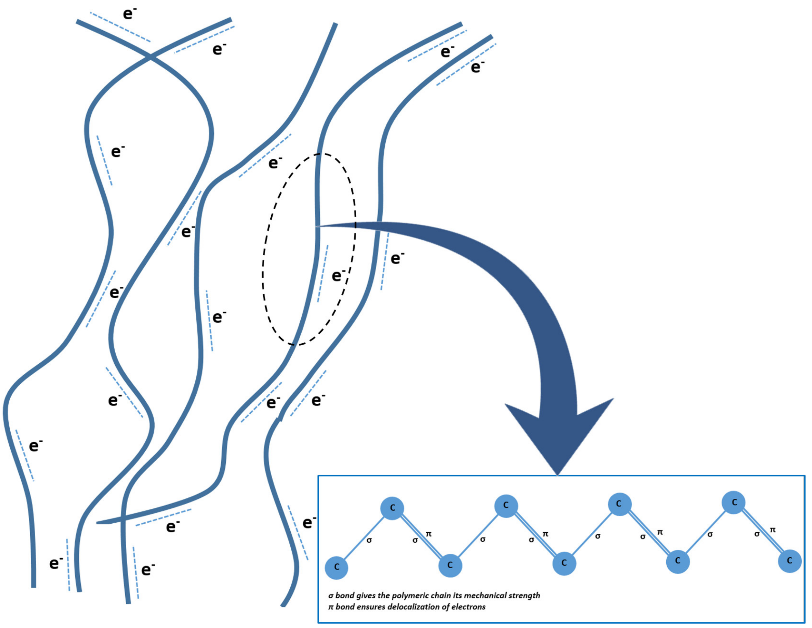
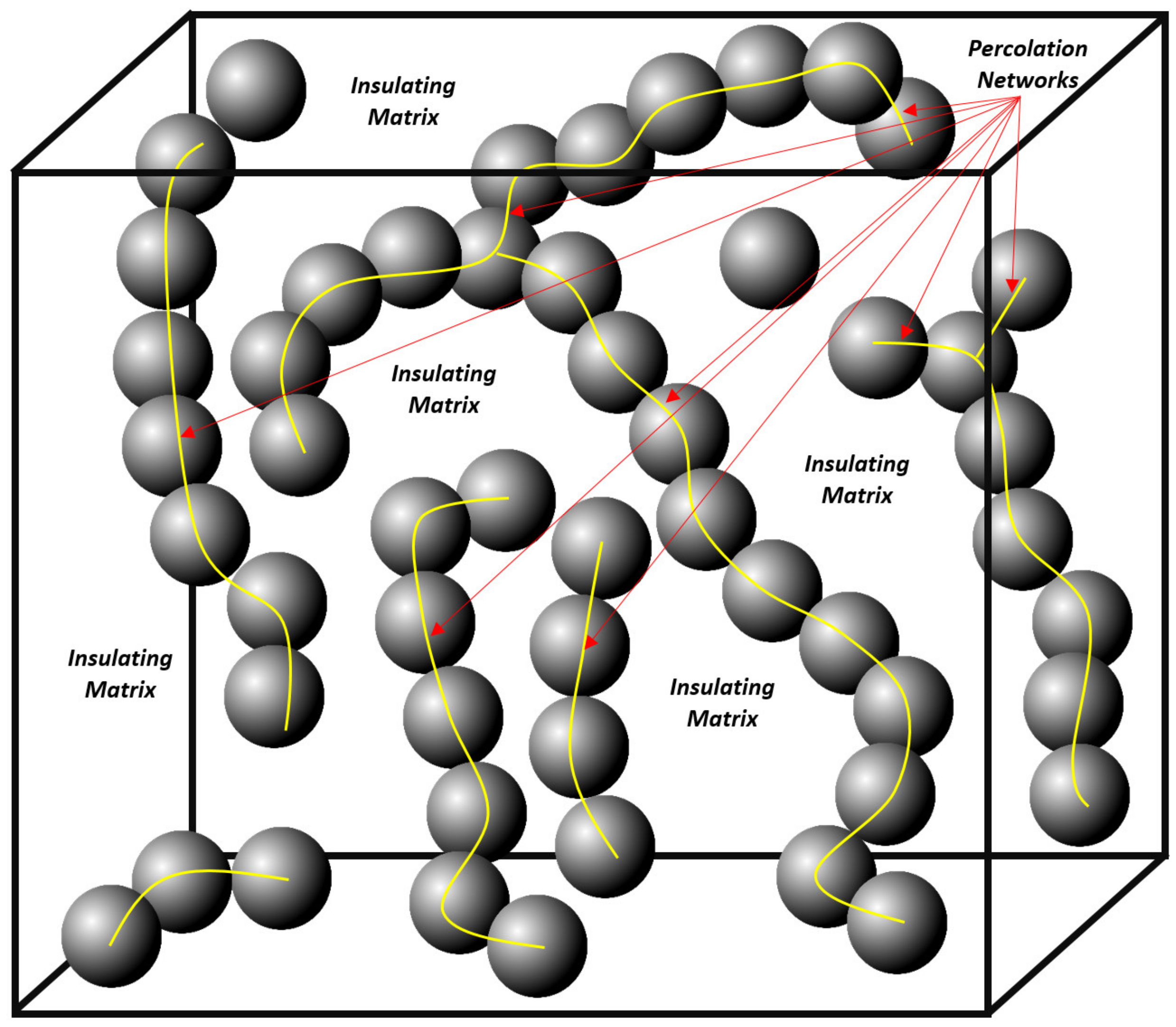
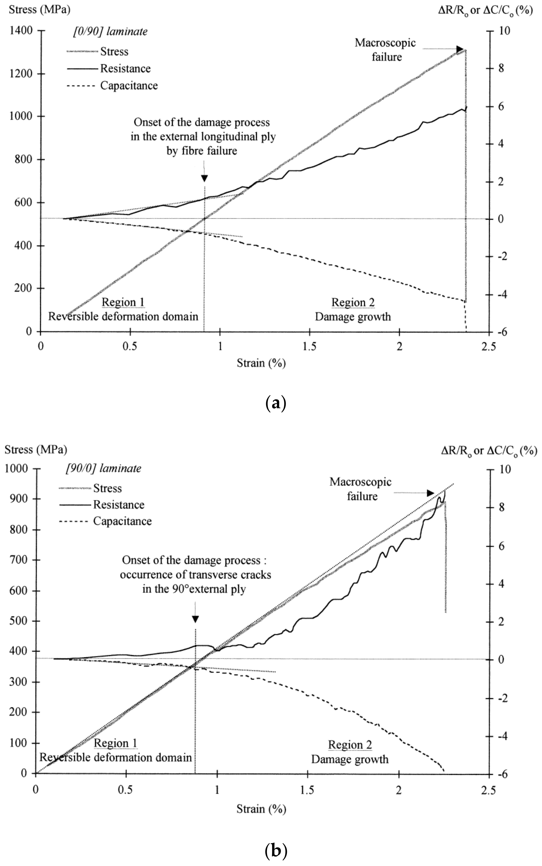
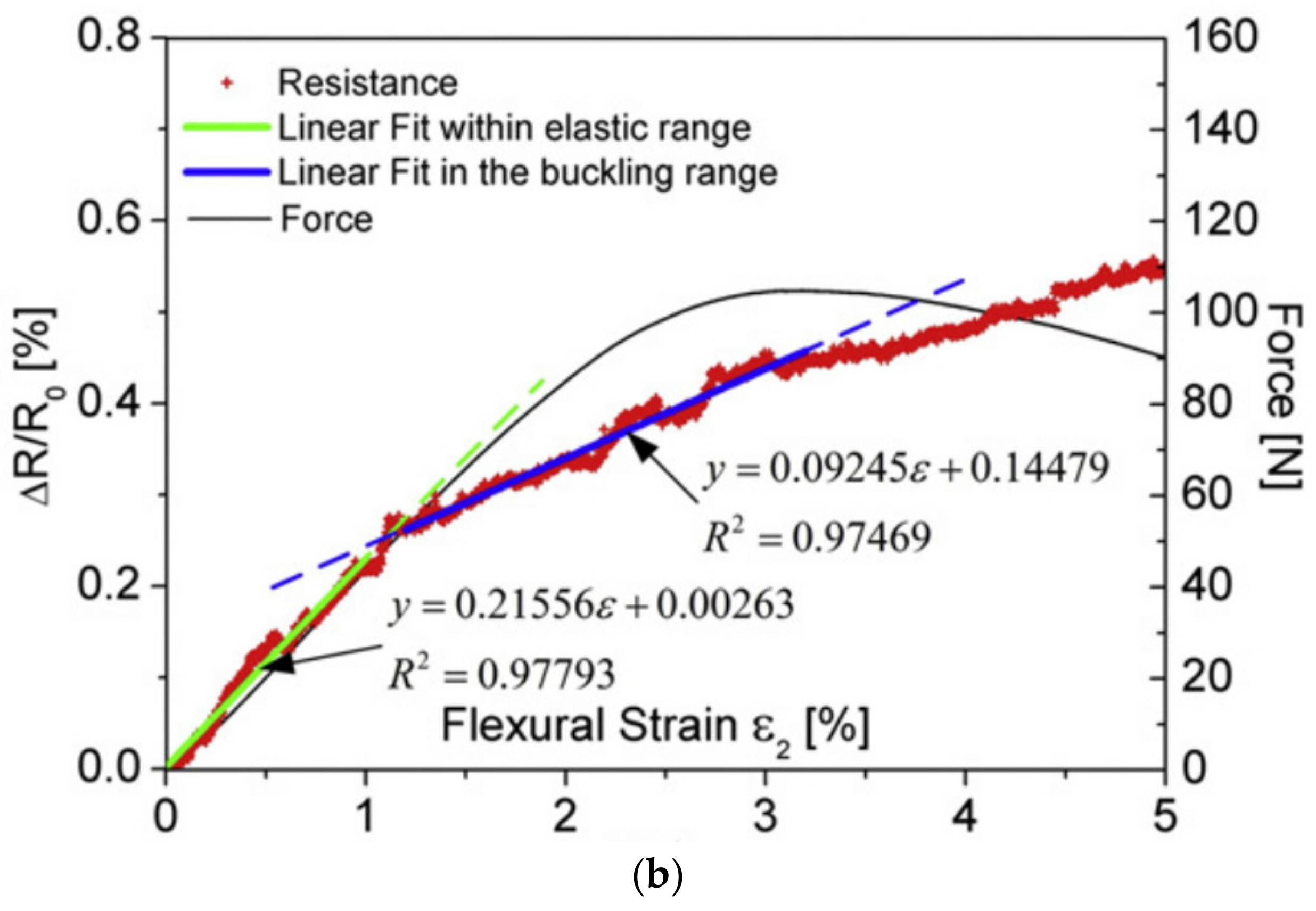
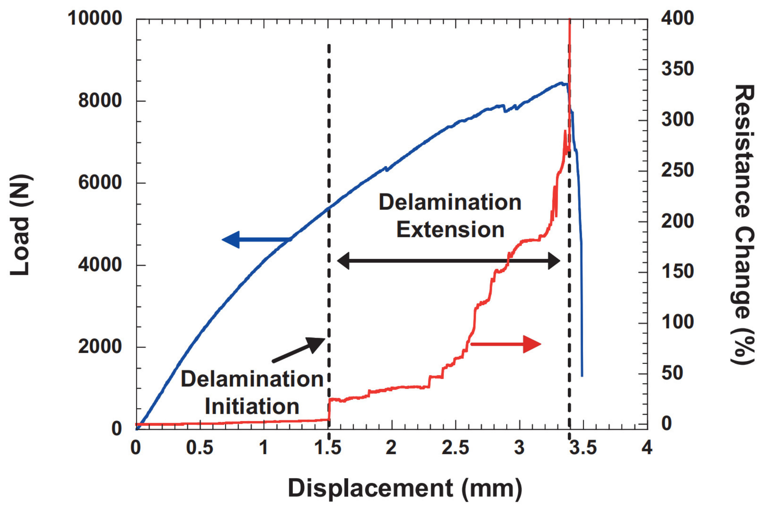
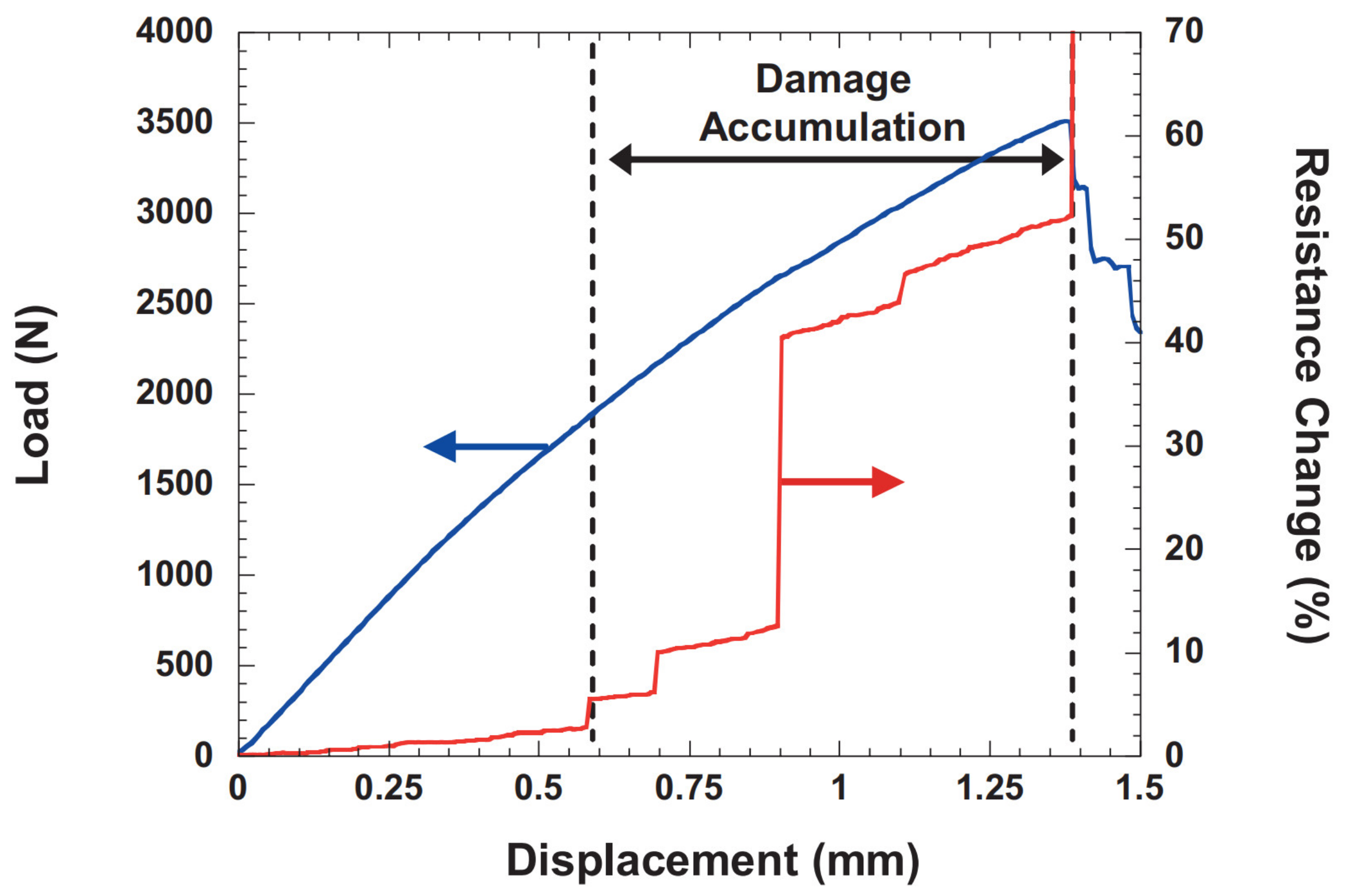
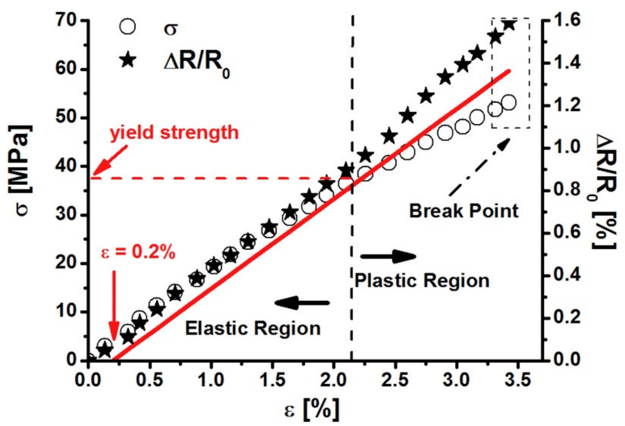
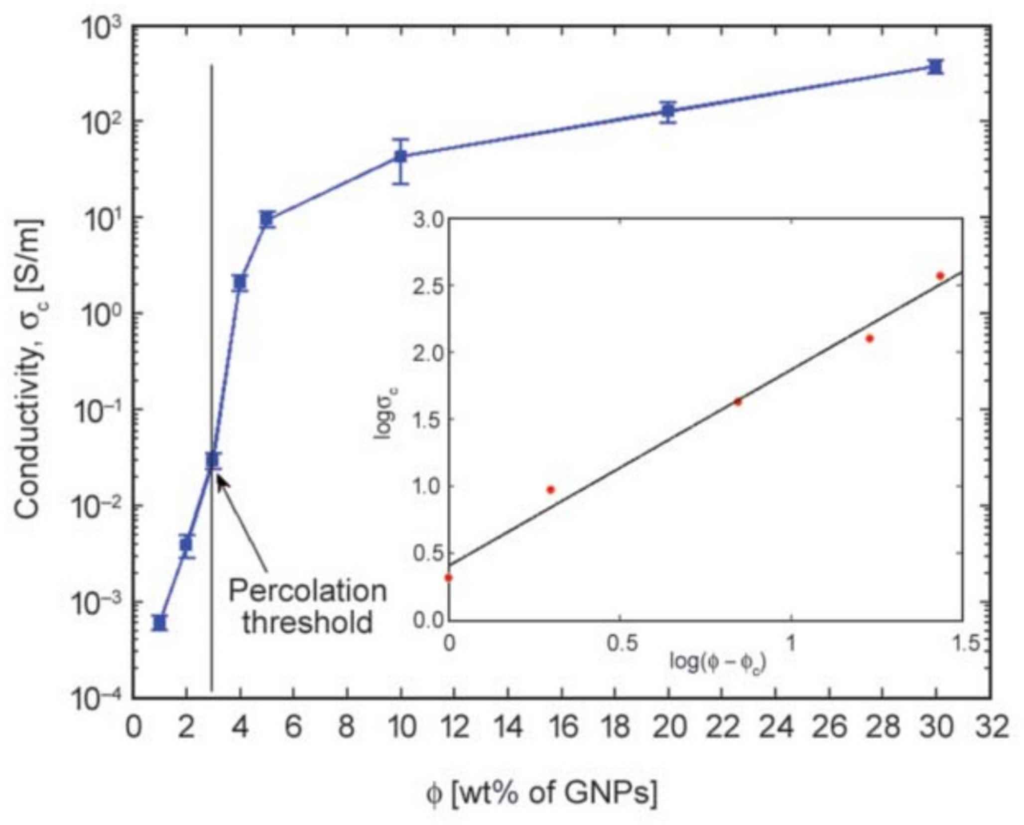
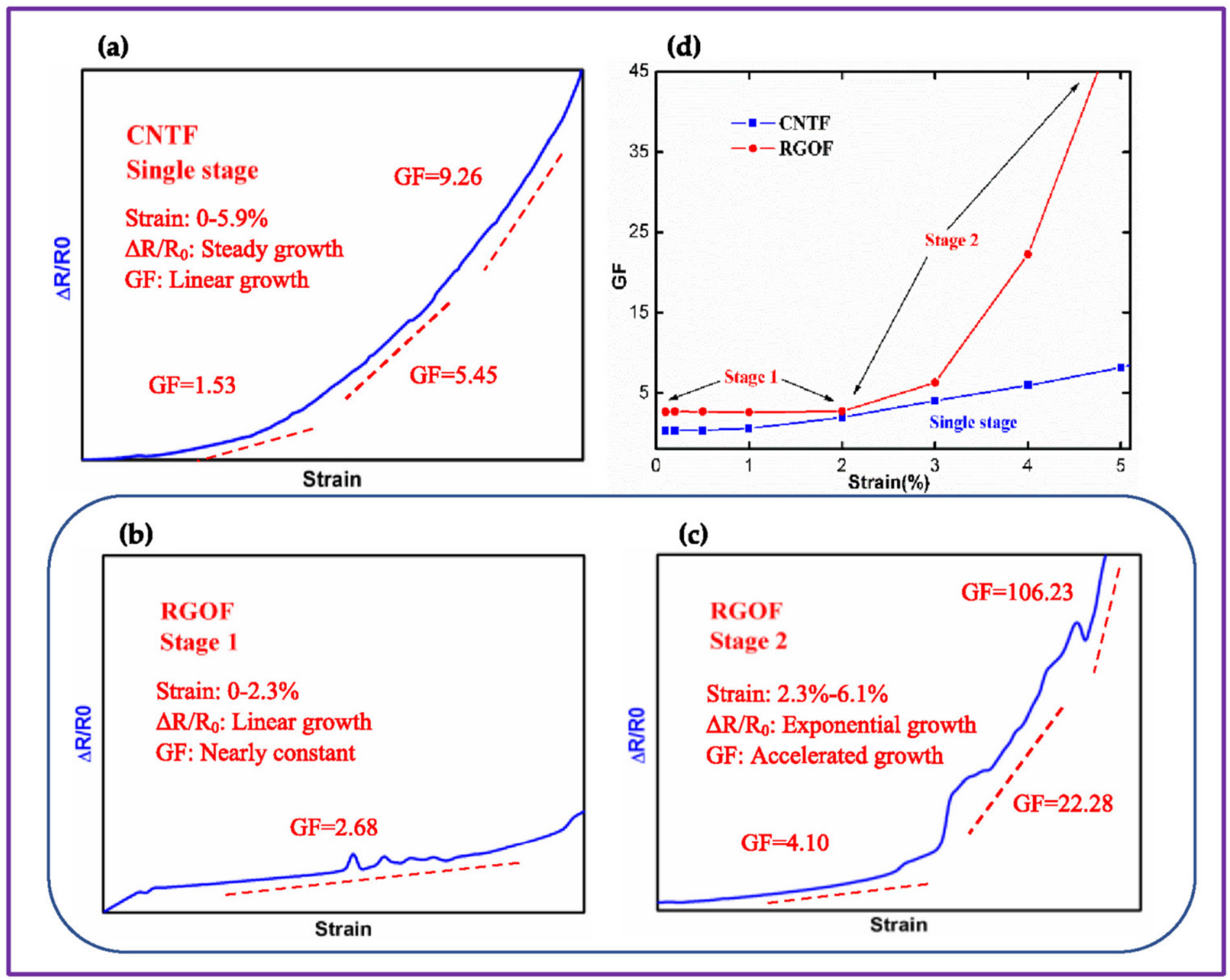
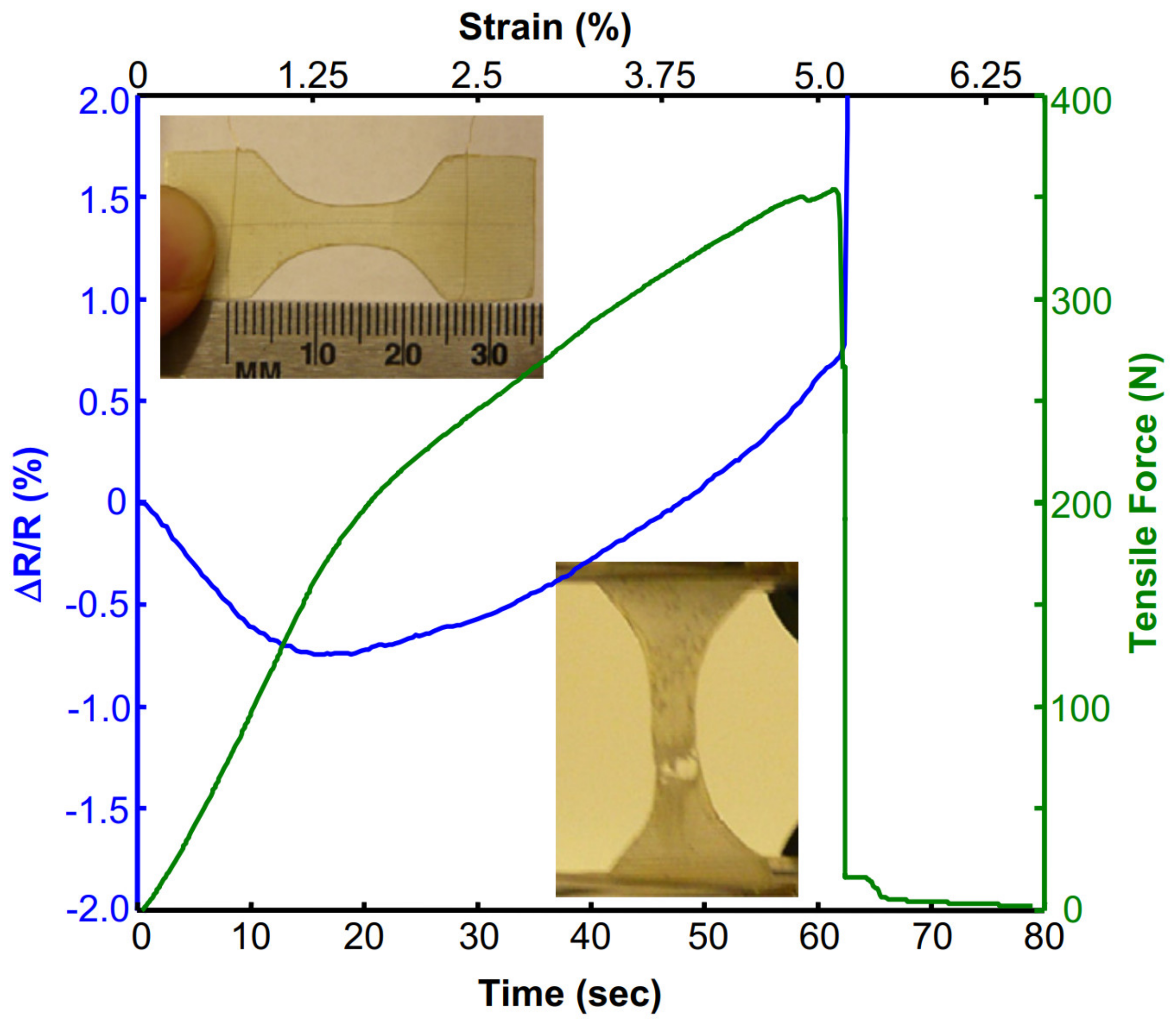
Table 1.
Comparative analysis of the four piezoresistive sensing approaches on the basis of adopted selection strategy.
Table 1.
Comparative analysis of the four piezoresistive sensing approaches on the basis of adopted selection strategy.
| Piezoresistive Sensing Approach | Sensitivity | Ease of Manufacturing | Performance Spectrum | Limitation |
|---|---|---|---|---|
| Self-sensing in carbon fiber reinforced composites | Not tailorable | Facile to more complex | Only fiber-dominated failure modes are detectable | Matrix-dominated failure may remain undetected |
| Piezoresistive matrices | Tailorable within certain limits | Dispersions are complex | Only matrix-dominated failure modes are detectable | Fiber-dominated failure may remain undetected |
| Surface deposited/mounted sensors | Tailorable | Facile to complex | Only capable of strain sensing | Response cannot be correlated with various failure modes |
| Embedded filaments/yarns | Tailorable | Facile | Capable of detecting matrix-dominated/fiber-dominated failure modes—Capable of cure monitoring | - |
Publisher’s Note: MDPI stays neutral with regard to jurisdictional claims in published maps and institutional affiliations. |
© 2021 by the author. Licensee MDPI, Basel, Switzerland. This article is an open access article distributed under the terms and conditions of the Creative Commons Attribution (CC BY) license (https://creativecommons.org/licenses/by/4.0/).
Share and Cite
MDPI and ACS Style
Nauman, S. Piezoresistive Sensing Approaches for Structural Health Monitoring of Polymer Composites—A Review. Eng 2021, 2, 197-226. https://0-doi-org.brum.beds.ac.uk/10.3390/eng2020013
AMA Style
Nauman S. Piezoresistive Sensing Approaches for Structural Health Monitoring of Polymer Composites—A Review. Eng. 2021; 2(2):197-226. https://0-doi-org.brum.beds.ac.uk/10.3390/eng2020013
Chicago/Turabian StyleNauman, Saad. 2021. "Piezoresistive Sensing Approaches for Structural Health Monitoring of Polymer Composites—A Review" Eng 2, no. 2: 197-226. https://0-doi-org.brum.beds.ac.uk/10.3390/eng2020013