1. Introduction
Continued developments in advanced manufacturing technologies are fundamentally altering the way components are designed and manufactured. Applying these advanced manufacturing technologies (e.g., leveraging advanced materials, data science, and rapid testing and deployment to decrease costs and development times) to nuclear reactor core design could yield the most benefit and ultimately improve future commercial viability [
1]. The US Department of Energy Office of Nuclear Energy (DOE-NE) Transformational Challenge Reactor (TCR) program is demonstrating this manufacturing-informed core design approach.
Core design activities under the design and analysis thrust of the TCR program are driven by manufacturing, with a focus on rapid prototyping and innovation to support a near-term deployment. When the constraints of conventional manufacturing methods are relaxed, the design space opens, enabling the exploration of more complex non-repeating geometries [
2] that are made of traditional or non-traditional materials. Initially, no specific design or application was selected or targeted before undertaking these core design activities. However, a set of hard constraints was subsequently established to narrow the design space, and several candidate core designs within this design space were generated and evaluated for manufacturability and performance to provide supporting technical information for a design downselection. Operating a system with a core that was designed with this methodology and manufactured with additive or other advanced manufacturing techniques would be revolutionary.
This paper presents the results obtained by applying advanced manufacturing technologies to the core design problem within the design and analysis activities of the DOE-NE TCR. From an initial set of design constraints, two fast-spectrum and two thermal-spectrum designs were developed and analyzed. These analyses included neutronics evaluations of the different designs, reflector and control system design studies, thermal performance under steady-state and transient scenarios, and system design activities.
1.1. Design Approach
The TCR core design process follows a rapid iterative approach (
Figure 1) that is organized as design
sprints loosely modeled after the agile software development paradigm. This design approach typically begins with a high-level scoping study of the nuclear characteristics to ensure that the primary requirements and all the constraints are met. Once a nuclear design with the appropriate properties is selected, then nuclear and thermal safety analyses are performed to ensure that the nuclear system performs according to safety requirements for normal operation at the selected power level and under all postulated accident scenarios. Computer-aided design (CAD) models of the key reactor components are constructed in parallel. Once a CAD model is complete, staff members manufacture the critical core test components using the appropriate manufacturing technology. Once the test components are manufactured, their critical properties are analyzed, including component strength, surface quality, and defects. Any identified issues are entered into the neutronic and CAD design portions to start additional iterations. These design iterations generally only require weeks to complete, so design maturation occurs quickly.
1.2. Constraints
The six high-level requirements of the reactor demonstration effort are generic enough that many reactor designs and types meet them. The programmatic, design, and manufacturing constraints eliminate or deprioritize specific options: (1) the reactor system must be designed, licensed, and constructed on an accelerated timeline; (2) major components and services that are not manufactured must be readily available (e.g., material, specifications, vendors) and procurable to meet the demonstration timeline, as these are not research and development efforts; (3) components made via additive manufacturing must be designed from materials for which the manufacturing process is well characterized, including microstructural analysis, imperfections, dimensional control, and surface roughness; (4) the core must be relatively small, preferably fitting within an envelope of 1 m3; (5) components, fuel, and core structure must follow applicable licensing requirements; and (6) the core must contain less than 250 kg of less than 20%-enriched high-assay low enriched uranium (HALEU).
1.3. Computational Tools and Software
Several computational tools were used for this effort. Primary neutronics calculations were performed using the Shift [
3,
4] Monte Carlo neutron transport tool developed and maintained at Oak Ridge National Laboratory (ORNL). Shift uses the same data libraries as SCALE [
5,
6] but was built to run efficiently on large-scale computational resources. SCALE/TRITON [
7] was used to provide some data relevant for transient calculations and to provide estimated source term data; SCALE sensitivity and uncertainty analysis tools [
8] were used for neutronic benchmarking efforts. The MCNP code versions 5 [
9] and 6.1 [
10] were also used for various calculations.
Primary core and system thermal hydraulic (TH) calculations were performed using TRACE version 5.0 [
11], and confirmatory calculations were performed with RELAP5/MOD3.3 [
12]. Some additional steady-state and transient 2D heat conduction calculations were performed using COMSOL [
13].
2. Key Design Features
Early development during the TCR program yielded several novel design features that are not typically used in existing reactors. These features include (1) a densely packed TRISO particle fuel in a SiC matrix formed with integrated cooling channels, (2) double-walled fuel cladding concepts with integrated spring features to enhance heat transfer, and (3) advanced solid hydrogenous neutron moderator materials. Further detail on each of these design features is provided in the following sections.
2.1. Dense TRISO/SiC Fuel Forms
In this work, uranium nitride (UN)-bearing TRISO fuel particles that were recently developed under DOE’s Advanced Fuels Campaign program at ORNL were used. Details of UN fuel kernels and TRISO particle production have been reported elsewhere in the literature [
14,
15,
16]. The larger and denser UN fuel kernel in this TRISO particle offers significantly higher uranium loading per unit volume compared with the smaller uranium oxide-carbide kernel in the reference TRISO design that was developed and extensively tested under the Advanced Gas Reactor program. This higher uranium loading per unit volume allowed the design team to realize functional TCR core designs within the 1 m
3 volume as set in the design goal.
Dense TRISO packing in which the particle packing fraction (i.e., ratio of volume of particles to overall volume of fuel compact) is above 40% when using a single particle size has been historically difficult to achieve because of the traditional manufacturing process. The theoretical maximum packing fraction for the traditional manufacturing process is ~48% as a result of two effects: (1) the process of die loading limits the precompression packing configuration so that it is stable under gravity, and (2) the 1D compression reduces only the axial dimension of the particle lattice rather than uniformly compressing the lattice [
17]. For reference, the maximum packing fraction for a random close pack of hard spheres without wall effects is 64% [
18,
19], so the traditional manufacturing process is not capable of approaching the theorical maximum packing fraction. Less-than-optimal particle packing results in larger, less neutronically efficient cores, so increasing the particle packing fraction would yield smaller cores with greater neutronic efficiency.
Under the TCR program, a new process was developed that yields highly dense (greater than 50% packing fraction) fuel blocks with internal coolant channels [
20,
21]. The process involved manufacturing an empty SiC shell with integrated cooling channels. TRISO particles were then poured into the empty shell, after which the TRISO-filled shell underwent a chemical vapor infiltration (CVI) process [
22]. Because TRISO particles are poured into the shell, the particle packing fraction can approach the maximum theoretical level of 64%. The CVI process does not involve a compaction step, so traditional particle over-coating and mixing with a matrix material is not needed. Instead, the CVI process is then used to essentially grow the SiC carbide matrix, eliminating the need for the compaction step. Using CVI to grow the matrix enables TRISO particles to be poured into the shell without a powdered matrix and allowed to contact one another, leading to a higher packing fraction than that is traditionally achieved. A more complete explanation of the process, properties, and performance of the fuel form as described in [
21].
2.2. Double-Walled Fuel Cladding with Conductive Structures
Although TRISO particle fuel can retain fission products naturally, traditional ceramic fuel materials such as UO2, UN, and UC, require an external fission product barrier (cladding) to retain fission gasses. In typical power reactors, cladding is made in a tubular form, and caps are welded onto each end of the tube after the fuel is inserted, forming a fuel pin. An engineered fuel cladding gap is designed into the fuel pins to accommodate the dimensional changes of the fuel pellet during irradiation at operating temperatures and to reduce the impact of the resulting pellet-cladding interaction on fuel integrity. This gap causes poor heat transfer between the fuel and the cladding, resulting in a large temperature drop (on the order of 100 °C in a pressurized water reactor) across this gap and an elevated peak fuel temperature. Improving conductivity across this gap will reduce the temperature drop and peak fuel temperature. The sintered fuel pellets inserted into the cladding must be milled before insertion to ensure the appropriate gap size.
Additive manufacturing processes can be used to manufacture cladding that is a few hundred microns in dimension, with very thin, internal spring-like structures to accommodate a traditionally manufactured fuel form and to improve heat transfer across the gap between the form and the cladding wall. These spring-like structures can be optimized to accommodate the dimensional changes within the fuel during reactor operation and to ensure it is always in contact with the fuel form, ensuring consistent heat transfer. Although simulation tools are reasonably predictive, several geometries can be manufactured to measure the heat transfer characteristics and to validate models with additive-enabled rapid prototyping and testing. Unfortunately, this feature adds material to the system that increases parasitic neutron capture.
In addition to internal spring-like structures, external coolant flow is directed via a double-walled cladding structure. As in the spring-like structures, the walls of the coolant flow structure are thin (less than 1 mm) and yield a very rigid overall structure. Like the TRISO/SiC fuel blocks, this type of flow structure can be designed to optimize the coolant channel size and the associated coolant flow path both radially and axially.
2.3. Advanced Neutron Moderator Materials
Efficiently using space and material is important to the core design thrust of the TCR program. Early in the development cycle, fast-spectrum systems were the design focus, but it was soon realized that the large quantity of HALEU required for fast-spectrum systems was limiting. As a result, the core design team began analyzing the feasibility of adding neutron-moderating materials to the system to reduce the HALEU mass requirements.
There are several typical moderator materials, including H
2O, D
2O, graphite, beryllium, and metal hydrides. To understand the impact of these types of materials while keeping the overall core size small, a simple parameter study was performed. A simple 1 m diameter spherical reactor core model was generated with a 50 cm graphite reflector and a 20 cm stainless steel core vessel. The internal core material compositions were assumed to consist of 15% (by volume) helium coolant, 15% stainless steel structure, and 70% UO
2 fuel + a moderator mixture. The composition of this fuel and the moderator mixture was then varied to consist purely of UO
2 through a pure moderator. The results shown in
Figure 2 indicate that when fuel is replaced with a moderator, only materials such as H
2O, YH
1.7, and ZrH
1.6 yield an increase in reactivity, as indicated by the local maxima. Beryllium metal, BeO, and graphite are not sufficiently efficient moderators to yield the same local maximum in reactivity, so adding these moderators is not as beneficial in terms of generating small core designs with low HALEU demands. Note that the curves for YH
1.7 and ZrH
1.6 in
Figure 2 overlap.
The TCR program’s choice of a high-temperature system precluded the use of water as a moderator, so metal hydrides were a clear choice for the moderating material. Although zirconium has a lower neutron capture cross section than yttrium, both are relatively low, so there is no significant difference in terms of neutron capture, as indicated by the overlapping curves for each in
Figure 2. Yttrium hydride was specifically selected, as it exhibits improved thermal stability over zirconium hydride.
Thermal stability refers to the equilibrium partial pressure of hydrogen as a function of temperature for these hydrides; it is approximately 3-fold smaller for yttrium hydride [
23,
24]. As a result, the driving force for hydrogen dissociation and the extent of the pressurization of hydride-bearing cladding are much lower for yttrium hydride compared with zirconium hydride at any given temperature. For the elevated-temperature application of metal hydride moderators, this represents a distinct advantage of yttrium hydride over zirconium hydride. The cladding material must withstand the expected hydrogen pressurization without failure, so the safe operating temperature depends on the design of the cladding. The safe operating temperature of a reactor using ZrH or YH is a function of the moderator, the chosen hydrogen barrier, and the system pressure. Higher temperature limits on the moderator could be obtained through use of a thicker cladding material or selection of a cladding material with lower hydrogen permeability at elevated temperature, each of which may result in a penalty on neutron economy. Safe operating temperatures for the YH and steel cladding system are being evaluated under the TCR program; however, the predicted YH temperatures are well below the expected design limit for the moderator and cladding system.
3. Candidate Core Designs
The candidate core designs leveraged combinations of the key design features outlined in
Section 2, resulting in two fast-spectrum designs and two thermal-spectrum designs. One of the fast-spectrum designs used the printed TRISO/SiC fuel form, and the other used the UO
2 fuel form that was contained in the hexagonal double-walled cladding structures. The same fuel forms were leveraged for the thermal designs—although the fuel was a different shape and size—and YH
x was added to the cores, yielding softer neutron spectra and lower HALEU requirements. An additively manufactured bottom flow structure was included in the thermal designs, enabling a two-pass coolant flow path through the core to keep the YH
x neutron moderator at sufficiently low temperatures to minimize hydrogen loss.
Neither the TRISO/SiC nor the UO2 fast-spectrum core designs met the basic requirement of using less than 250 kg of HALEU, so efforts for optimization and additional analysis were minimized for these designs. A higher-worth neutron reflector, a reduction in coolant channel size, or other design modifications would not yield critical cores of these designs with less than 250 kg of HALEU, so the remainder of the work has focused on the thermal-spectrum designs.
3.1. Core Manufacturing
Both thermal-spectrum core designs include bidirectional coolant flow that travels down through the moderator elements and then up through the fuel elements. The structure below the core contains flow channels that direct the coolant from the moderator elements to the fuel elements. This portion will be additively manufactured, and then the structure (cladding) for the moderator elements will be additively manufactured as a monolith simultaneously with the bottom plate structure. The YH1.7 moderator will be incorporated into this monolith as sets of hexagonal or part-hexagonal plates. Each of the moderator-containing columns of this monolith will be welded to encapsulate the YH1.7.
Fuel elements (either UO2 encased in the double-walled cladding structure or TRISO-filled SiC elements) will then be placed into this monolith to form the core. A subsection of the core is being printed as a flow test article to validate computational fluid dynamics simulations and to test the manufacturing steps that are required to construct the core. Although the fuel elements of the UO2/YHx/steel and TRISO/YHx/steel design do not have the same dimensions, identically sized fuel elements are being constructed to test fuel element fitting within the additively manufacturing structure.
3.2. UO2/YHx/Steel Thermal-Spectrum Design
For this core design concept, YH
x is combined with the double-walled fuel cladding with conductive structures. The layout of fuel and moderator follows an underlying hexagonal pattern; the moderator is contained in hexagonal-shaped steel cladding structures and the fuel is contained in the Y-shaped fuel elements surrounding the moderator. The traditionally manufactured fuel elements are enclosed in the double-walled cladding structure, but the moderator is contained in a single-layer bounding hexagon. The moderator is contained in hexagonal elements instead of the fuel to reduce hydrogen migration from the moderator during operation. Hexagons have a higher volume-to-surface area ratio than the Y-shaped elements, so hydrogen migration from the bulk material is minimized. In this concept, the core is ~60 cm in diameter and ~70 cm in length (
Figure 3).
The cooling channels surrounding the fuel elements contain an internal structure to improve heat transfer across gaps, a sandwich structure through which the coolant flows and mixes, and external fitment structures to enable assembly in the core. The sandwich structure reduces the amount of parasitic steel within the core and incorporates coolant mixing features that are not traditionally manufacturable. The full detail in the CAD models cannot currently be modeled precisely in the neutronic models; however, the major dimensions (double-wall thickness) and overall material masses are conserved. This core design concept requires approximately 200 kg of HALEU, thus meeting the fuel use requirement.
3.3. TRISO/YH/Steel Thermal-Spectrum Design
For this core design concept, YH
x is combined with the TRISO/SiC fuel elements. As in the UO
2/YH/steel design, the layout of fuel and moderator follows an underlying hexagonal pattern, with the moderator contained in hexagonal-shaped steel cladding structures and the fuel contained in the Y-shaped fuel elements surrounding the moderator. In this concept, the core is ~80 cm in diameter and ~95 cm in length (
Figure 4).
Although not shown in
Figure 4, the fuel elements contain ~40% coolant flow by volume. The TRISO materials and dimensions for this design are as follows: a central 800 μm diameter fuel kernel of UN, coated with a carbon buffer (50 μm), inner pyrocarbon (35 μm), SiC (30 μm), and outer pyrocarbon (35 μm). In the candidate design, a 50% TRISO packing fraction is assumed in the fuel meat portion of the fuel elements, with SiC occupying the rest of the fuel meat volume. The SiC in the fuel meat portion is assumed to be 80% theoretical density, as the process does not yet yield fully dense SiC.
Feasible cores using this design concept contain ~175 kg of HALEU, thus meeting the primary fuel use requirement. This design concept yields a larger core than the UO2/YH/steel design (80 cm vs. 60 cm core diameter). However, this design concept requires less HALEU because the UO2/YH/steel concept uses a more uranium-dense fuel form (solid UO2 hexes vs. dispersed TRISO fuel) and the UO2/YH/steel contains more neutron-absorbing steel in the core, whereas the TRISO design uses SiC instead of steel for fuel cladding.
4. Core Thermal Hydraulic Analyses
Steady-state and transient TH analyses were performed to estimate the temperatures and other system response variables during steady-state operation and anticipated accident events. Analyses were carried out for 1, 6, and 12 MWth total core operating power levels to assess the operating power level impact on TH and safety performance. Both the UO2/YH/steel and TRISO/YH/steel thermal designs were considered in the analyses, and representative geometric and neutronic inputs were used for each design.
4.1. Thermal Hydraulic Models
Steady-state TH results were generated using a simple analytical model and a RELAP5-3D model for power levels of 1, 6, and 12 MW
th. Simple unit cell models for determining core temperatures, velocities, and pressure drops were implemented using Python to provide scoping estimates of steady-state core performance. Temperature- and pressure-dependent helium property correlations were used. Although the TCR will operate for a short duration, the analyses in this report assume the lower value of 8 W/m-K to be consistent with the lowest thermal conductivity expected in the 3D-printed SiC after saturation of irradiation defects in this material [
25].
A single-loop, single-channel RELAP5-3D model was created to analyze the steady-state and transient behavior of the TCR. The RELAP model comprises six hydrodynamic volumes that form an enclosed primary loop: the reactor core, the hot leg, a heat exchanger, the low-pressure cold leg, a helium circulator, and the high-pressure cold leg. Core power during the transient analyses is determined using point kinetics with reactivity feedback based on the volume-averaged fuel temperature in the core.
4.2. Steady-State Results
Under the same total core flow rate at each power level, the TRISO/YH/steel design gave a core pressure drop approximately 50% higher than that in the UO
2 design (
Table 1 and
Table 2). Despite the approximately 2× lower velocity for TRISO/YH/steel, the increased core height, smaller coolant channels, and corresponding higher friction factor more than compensated for the velocity difference, leading to the higher pressure drop in the TRISO/YH/steel design.
The larger core volume in the TRISO/YH/steel design yielded a lower power density for a given core power level. This was the main factor that led to a lower convective (i.e., cladding temperature minus coolant bulk temperature) for TRISO/YH/steel. The lower power density, as well as the ~3× higher conductivity and smaller fuel thickness for TRISO/YH/steel, resulted in an ~100× lower across the fuel region compared with that in the UO2 design. This became ~200× lower when the temperature rise across the UO2 gap was also considered. In terms of fuel temperatures, the TRISO/YH/steel design greatly benefited from the lack of an open gap between the fuel and cladding. At 12 MWth, the UO2 peak fuel temperature (3605 K) exceeded the UO2 melting point (3120 K) for the current geometric and operating conditions at steady state. The current UO2 design required significantly lower operating power levels to avoid fuel failure compared with the current TRISO/YH/steel design.
4.3. Pressurized Loss of Forced Circulation (P-LOFC) with Scram
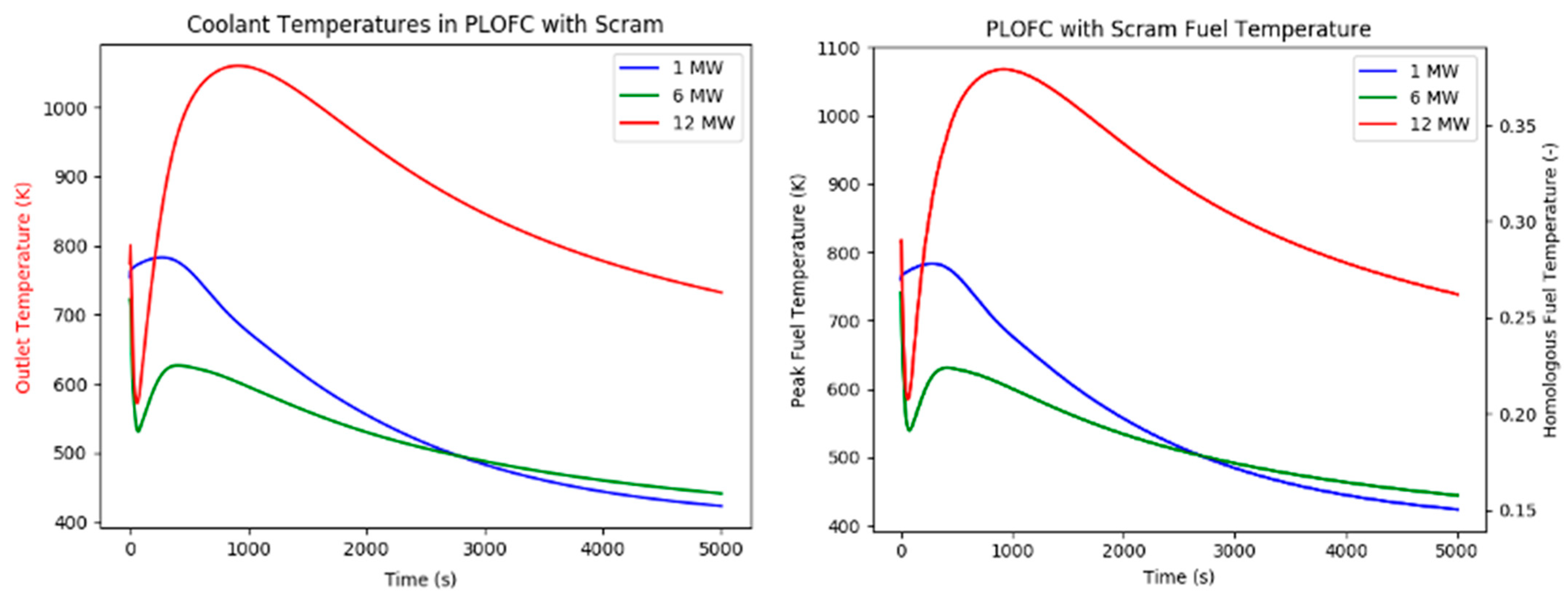
One of the postulated accident scenarios involves an unplanned trip and coastdown of the primary flow circulator starting from nominal operating conditions. The circulator trip signal initiates an automatic scram, which is conservatively assumed to be initiated 10.0 s after the trip and is completed 10.0 s later.
RELAP results for the P-LOFC event with scram are shown in
Figure 5. The natural circulation flowrate depends primarily on the total height of the primary loop and the frictional losses throughout the loop with initial conservative estimates. The results indicate that the TRISO/YH/steel core can withstand a P-LOFC event at operating power levels up to and including 12 MW. The fuel temperatures of the UO
2 core remain beneath the melting point for operation up to and including 6 MW (not shown).
5. Conclusions
In 2019, the objective of the DOE-NE TCR program design and analysis thrust was to demonstrate a rapid, iterative approach to core design in which designs are modified and analyzed and subcomponents are manufactured in parallel over time frames of weeks instead of months or years. To meet key program initiatives (e.g., timeline, material use), several constraints—including fissile material availability (less than 250 kg of HALEU), component availabilities, materials compatibility, and additive manufacturing capabilities—were factored into the design effort, yielding small (less than 1 m3 in volume) cores with near-term viability.
With significant progress made on advanced moderator materials (YHx) under the TCR program, gas-cooled thermal-spectrum systems using less than 250 kg of HALEU and occupying less than 1 m3 became feasible. Two system designs were developed—a traditional UO2 ceramic fuel with YHx moderator and UN-bearing TRISO fuel particles embedded inside a SiC matrix with YHx moderator. Both systems met the major design requirements; however, differences in their thermal performance were evident.
The thermal performance of the TRISO/YH/steel and UO2/YH/steel designs was analyzed and verified for power levels of 1, 6 and 12 MWth. The TRISO/YH/steel system produced acceptable temperatures for an operating power levels up to 6 MWth. The UO2/YH/steel system produced significantly more limiting transient behavior, indicating that operation of the current UO2 design should be limited to approximately 1 MWth. Future design modifications could potentially improve the UO2 system performance, such as enlarging the physical size of the core and reducing the power density per unit volume, to mitigate the inherent TH disadvantages of the UO2/YH/steel design relative to the TRISO/YH/Steel design.
Author Contributions
Conceptualization, methodology, neutronic analyses, B.J.A. and B.R.B.; Neutronic analyses, J.R.B., B.D.H., A.B., J.W.S., and T.V.H.; systems analysis and safety calculations, A.J.W., J.D.R., N.R.B., and R.F.K.; system conceptualization and analysis, M.S.G.; thermomechanical and thermofluidic design, P.K.J.; mechanical design and additive manufacturing, P.C.C., and J.J.W.H.; conceptualization, supervision, project administration, and funding acquisition, K.A.T.; supervision, and project administration, F.H. All authors have read and agreed to the published version of the manuscript.
Funding
This work was funded under the Department of Nuclear Energy Office of Nuclear Energy Transformational Challenge Reactor program.
Data Availability Statement
This manuscript has been authored by UT-Battelle, LLC, under contract DE-AC05-00OR22725 with the US Department of Energy (DOE). The US government retains and the publisher, by accepting the article for publication, acknowledges that the US government retains a non-exclusive, paid-up, irrevocable, worldwide license to publish or reproduce the published form of this manuscript, or allow others to do so, for US government purposes. DOE will provide public access to these results of federally sponsored research in accordance with the DOE Public Access Plan (
http://energy.gov/downloads/doe-public-access-plan).
Acknowledgments
The authors would like to thank program sponsors for supporting and encouraging this work. Thanks also go to Rose Raney for technical editing this manuscript and ORNL Manufacturing Demonstration Facility staff who assisted in manufacturing test components of the systems.
Conflicts of Interest
The authors have no existing conflict of interest.
References
- Betzler, B.R.; Ade, B.J.; Wysocki, A.J.; Greenwood, M.S.; Heineman, J.J.W.; Chesser, P.C.; Jain, P.K.; Heidet, F.; Bergeron, A. Advanced Manufacturing for Nuclear Core Design; ORNL/TM-2019/1258; Oak Ridge National Laboratory: Oak Ridge, TN, USA, 2019. [Google Scholar]
- Sobes, V.; Hiscox, B.; Popov, E.; Delchini, M.; Archibald, R.; Hauck, C.; Laiu, P.; Betzler, B.; Terrani, K. Artificial Intelligence Design of Nuclear Systems Empowered by Advanced Manufacturing. In European Physical Journal Web of Conferences; PHYSOR 2020—Transition to a Scalable Nuclear Future; EDP Sciences: Cambridge, UK, 2020. [Google Scholar]
- Pandya, T.M.; Johnson, S.R.; Evans, T.M.; Davidson, G.G.; Hamilton, S.P.; Godfrey, A.T. Implementation, Capabilities, and Benchmarking of Shift, a Massively Parallel Monte Carlo Radiation Transport Code. J. Comput. Phys. 2016, 308, 239–272. [Google Scholar] [CrossRef] [Green Version]
- Davidson, G.G.; Pandya, T.M.; Johnson, S.R.; Evans, T.M.; Isotalo, A.E.; Gentry, C.A.; Wieselquist, W.A. Nuclide Depletion Capabilities in the Shift Monte Carlo Code. Ann. Nucl. Energy 2018, 114, 259–276. [Google Scholar] [CrossRef]
- Wieselquist, W.A.; Lefebvre, R.A.; Jessee, M.A. (Eds.) SCALE Code System, ORNL/TM-2005/39, Version 6.2.4; Oak Ridge National Laboratory: Oak Ridge, TN, USA, 2020. [Google Scholar]
- Bowman, S.M. SCALE 6: Comprehensive Nuclear Safety Analysis Code System. Nucl. Technol. 2011, 174, 126–148. [Google Scholar] [CrossRef]
- DeHart, M.D.; Bowman, S.M. Reactor physics methods and analysis capabilities in SCALE. Nucl. Technol. 2011, 174, 196–213. [Google Scholar] [CrossRef]
- Williams, M.L.; Rearden, B.T. SCALE-6 Sensitivity/Uncertainty Methods and Covariance Data. Nucl. Data Sheets 2008, 109, 2796–2800. [Google Scholar] [CrossRef]
- X-5 Monte Carlo TeamTeam, X.; Monte, C. Mcnp—Version 5, Vol. I: Overview and Theory; LA-UR-03-1987; Los Alamos National Laboratory: Los Alamos, NM, USA, 2003. Available online: https://mcnp.lanl.gov/pdf_files/la-ur-03-1987.pdf (accessed on 1 September 2019).
- Goorley, J.T.; James, M.R.; Booth, T.E.; Brown, F.B.; Bull, J.S.; Cox, L.J.; Durkee, J.W.; Elson, J.S.; Fensin, M.L.; Forster, R.A.; et al. Initial Mcnp6 Release Overview—Mcnp6 Version 1.0; LA-UR-13-22934; Los Alamos National Laboratory: Los Alamos, NM, USA, 2013. Available online: https://laws.lanl.gov/vhosts/mcnp.lanl.gov/pdf_files/la-ur-13-22934.pdf (accessed on 1 September 2019).
- U.S. Nuclear Regulatory Commission. Trace V5.0 Theory Manual—Field Equations, Solution Methods, and Physical Models; US Nuclear Regulatory Commission: Rockford, MD, USA, 2010. Available online: https://www.nrc.gov/docs/ML0710/ML071000097.pdf (accessed on 1 September 2019).
- Nuclear Safety Analysis; Division. Relap5/Mod3.3 Code Manual; NUREG/CR-5535/Rev 1-Vol I; Information Systems Laboratories, Inc.: Rockville, MD, USA; Idaho Falls, ID, USA, 2001; Available online: http://www.edasolutions.com/old/RELAP5/RELAP5M33/Manuals/volume1.pdf (accessed on 1 September 2019).
- COMSOL Inc. Comsol Multiphysics User’s Guide, Version 4.2; COMSOL Inc.: Burlington, MA, USA, 2011. [Google Scholar]
- Hunt, R.D.; Silva, C.M.; Lindemer, T.B.; Johnson, J.A.; Collins, J.L. Preparation of Uc0.07−0.10n0.90−0.93 Spheres for Triso Coated Fuel Particles. J. Nucl. Mater. 2014, 448, 399–403. [Google Scholar] [CrossRef]
- Lindemer, T.B.; Silva, C.M.; Henry, J.J.; McMurray, J.W.; Voit, S.L.; Collins, J.L.; Hunt, R.D. Quantification of Process Variables for Carbothermic Synthesis of Uc1-Xnx Fuel Microspheres. J. Nucl. Mater. 2017, 483, 176–191. [Google Scholar] [CrossRef] [Green Version]
- McMurray, J.W.; Kiggans, J.O.; Helmreich, G.W.; Terrani, K.A. Production of near-Full Density Uranium Nitride Microspheres with a Hot Isostatic Press. J. Am. Ceram. Soc. 2018, 101, 4492–4497. [Google Scholar] [CrossRef]
- Morris, R.N.; Pappano, P.J. Estimation of Maximum Coated Particle Fuel Compact Packing Fraction. J. Nucl. Mater. 2007, 361, 18–29. [Google Scholar] [CrossRef]
- Scott, G.D.; Kilgour, D.M. The Density of Random Close Packing of Spheres. J. Phys. D Appl. Phys. 1969, 2, 863–866. [Google Scholar] [CrossRef]
- Torquato, S.; Truskett, T.M.; Debenedetti, P.G. Is Random Close Packing of Spheres Well Defined? Phys. Rev. Lett. 2000, 84, 2064. [Google Scholar] [CrossRef] [PubMed] [Green Version]
- Terrani, K.A.; Trammell, M.P.; Jolly, B.C. Additive Manufacturing of Complex Objects Using Refractory Matrix Materials. U.S. Patent Application No. 16/527,317, 21 May 2020. [Google Scholar]
- Terrani, K.A.; Jolly, B.C.; Trammell, M.P.; Vasadevamurthy, G.; Schappel, G.; Ade, B.; Helmreich, G.W.; Wang, H.; MarquizRossy, A.; Betzler, B.R.; et al. Architecture and Properties of Tcr Fuel Form. J. Nucl. Mater. 2021, 152781. [Google Scholar] [CrossRef]
- Caputo, A.J.; Lackey, W.L. Fabrication of Fiber-Reinforced Ceramic Composites by Chemical Vapor Infiltration. In Proceedings of the 8th Annual Conference on Composites and Advanced Ceramic Materials: Ceramic Engineering and Science Proceedings, Cocoa Beach, FL, USA, 15–18 January 1984; Available online: https://0-ceramics-onlinelibrary-wiley-com.brum.beds.ac.uk/doi/abs/10.1002/9780470320228.ch20 (accessed on 1 August 2019).
- Begun, G.M.; Land, J.F.; Bell, J.T. High Temperature Equilibrium Measurements of the Yttrium–Hydrogen Isotope (H2, D2, T2) Systems. J. Chem. Phys. 1980, 72, 2959–2966. [Google Scholar] [CrossRef]
- Wang, W.E.; Olander, D.R. Thermodynamics of the Zr-H System. J. Am. Ceram. Soc. 1995, 78, 3323–3328. [Google Scholar] [CrossRef]
- Field, K.G.; Simpson, J.; Gussev, M.N.; Wang, H.; Li, M.; Zhang, X.; Chen, X.; Koyanagi, T.; Kane, K.; Marquez Rossy, A.; et al. Handbook of Advanced Manufactured Material Properties from Tcr Structure Builds at Ornl—Fy 2019; ORNL/TM-2019/1328; Oak Ridge National Laboratory: Oak Ridge, TN, USA, 2019. [Google Scholar]
| Publisher’s Note: MDPI stays neutral with regard to jurisdictional claims in published maps and institutional affiliations. |
© 2021 by the authors. Licensee MDPI, Basel, Switzerland. This article is an open access article distributed under the terms and conditions of the Creative Commons Attribution (CC BY) license (http://creativecommons.org/licenses/by/4.0/).

 ,
, 


