Practical Aspects of Acoustic Leaky-Wave Antennas Applied to Underwater Direction Finding †

 , ,
, ,  ,
,  and
and
Abstract
:1. Introduction
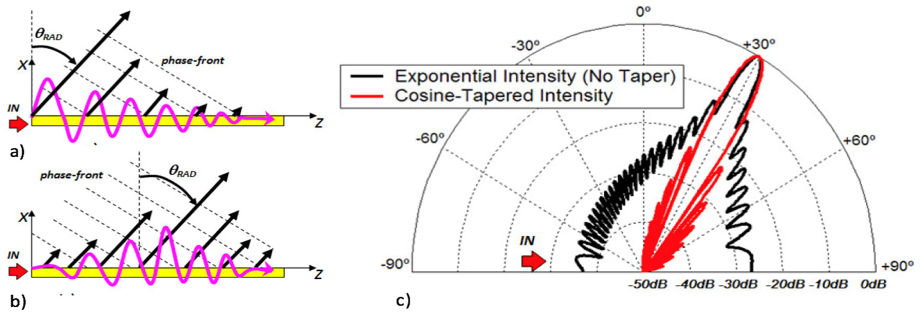
2. Theoretical Framework
3. Numerical Modelling and Performance
4. Results
4.1. Direction-of-Arrival (DoA)
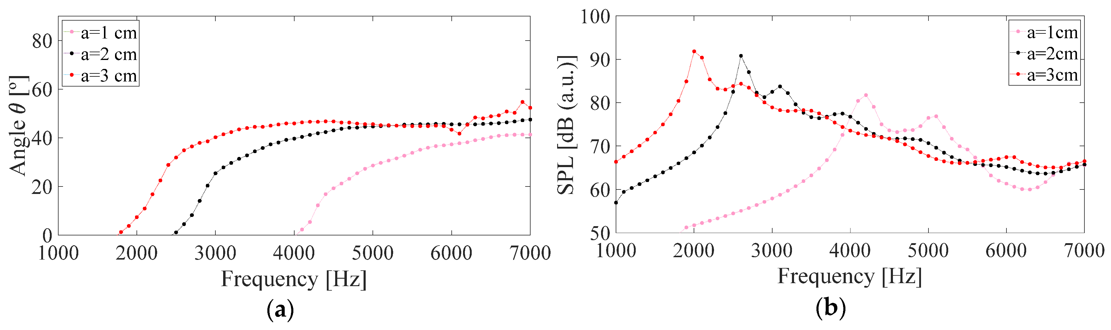
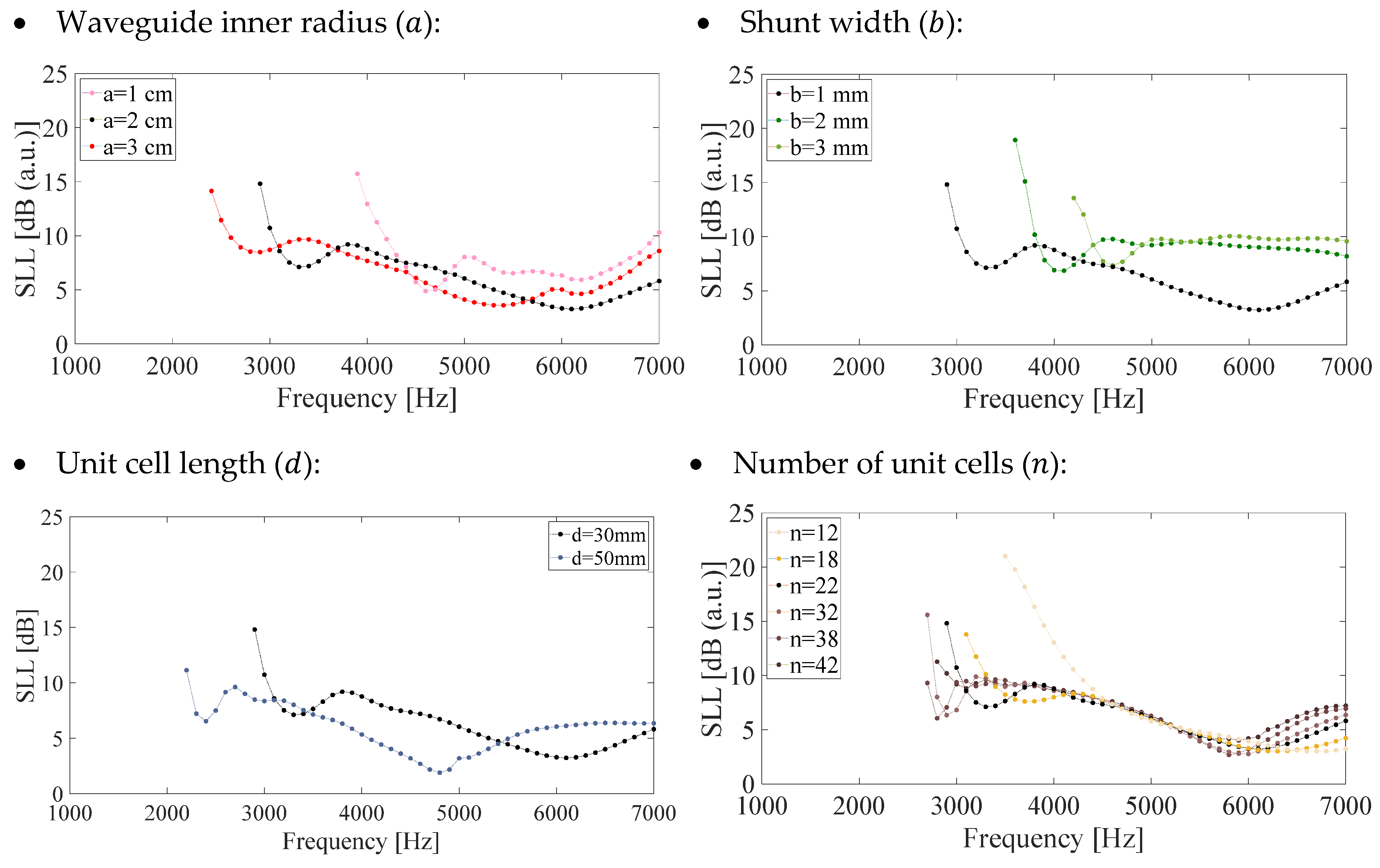
- Waveguide inner radius (): Regarding the radiation angle, by increasing 1 cm the radius (increase x×2 the radius or, equivalently, x×4 the section area), the lower frequency of radiation reduces from 2500 to 1800 Hz; by reducing 1 cm the radius (x×1/2 the radius or x×1/4 the section area), this frequency increases to 1800 Hz. Regarding the SPL, as the radius decreases, the radiation levels also decrease following a similar profile, with peaks about +3 dB at cut-off frequencies as shown in Figure 4.Figure 4. (a) Frequency dependence of the main radiation angle and (b) sound pressure level, for different waveguide inner radius ().Figure 4. (a) Frequency dependence of the main radiation angle and (b) sound pressure level, for different waveguide inner radius ().
![Engproc 02 00093 g004]()
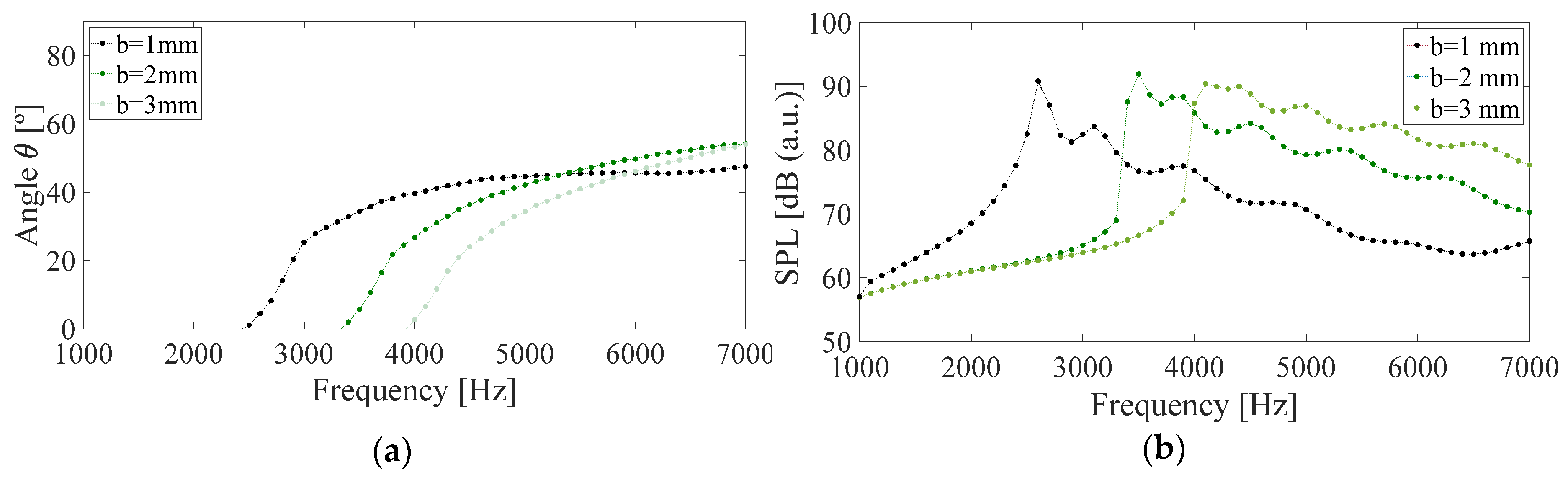
- Shunt width (): By increasing 1 and 2 mm the shunt width (×2 and ×3), the cut-off frequency increases from 2500 Hz to 3400 and 4000 Hz, respectively, slightly increasing the radiation angle for high frequencies (Figure 5). While the levels of the first radiation peak located at the starting frequency are quite similar, the SPL decreases with frequency more slowly as the parameter increases.Figure 5. (a) Frequency dependence of the main radiation angle and (b) sound pressure level, for different shunt widths ().Figure 5. (a) Frequency dependence of the main radiation angle and (b) sound pressure level, for different shunt widths ().
![Engproc 02 00093 g005]()
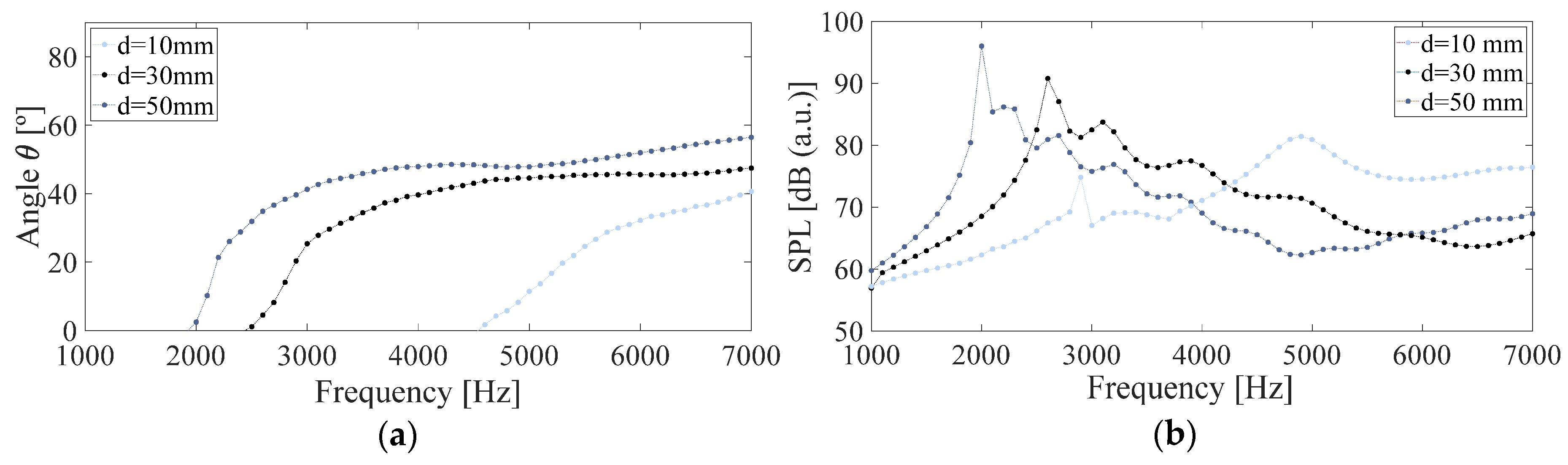
- Unit cell length (): When increasing the unit cell length from 30 to 50 mm (×1.7), the frequency is slightly reduced from 2500 to 2000 Hz, while when reducing it to 10 mm (×1/3), it is considerably increased up to 4600 Hz as shown in Figure 6. Regarding sound pressure levels, the corresponding peaks to the initial radiation frequencies decrease with the unit cell length, while the tails for higher frequencies decrease more rapidly for larger unit cell lengths.Figure 6. (a) Frequency dependence of the main radiation angle and (b) sound pressure level, for different unit cell lengths ().Figure 6. (a) Frequency dependence of the main radiation angle and (b) sound pressure level, for different unit cell lengths ().
![Engproc 02 00093 g006]()
- Shunt length (): For lengths between 1.25 and 10 cm (one order of magnitude), radiation varies between 2000 and 4000 Hz (factor two of variation), while maximum radiation angles decreases from 60 to 40 degrees. Although the levels of the first radiation peak located at the starting frequency are quite similar (except to = 10 cm), the SPL decreases with frequency more slowly as the parameter decreases (Figure 7).Figure 7. (a) Frequency dependence of the main radiation angle and (b) sound pressure level, for different shunt lengths ().Figure 7. (a) Frequency dependence of the main radiation angle and (b) sound pressure level, for different shunt lengths ().
![Engproc 02 00093 g007]()
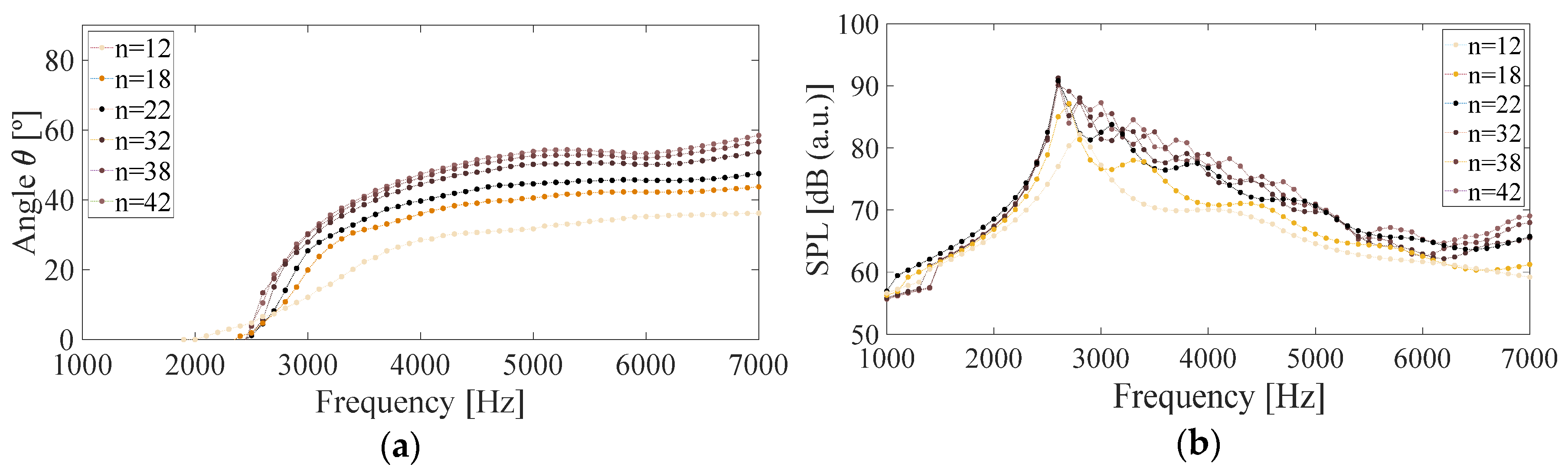
- Number of unit cells (): It can be seen that, on the one hand, that the lower radiation frequency does not change with the change in the number of cells (this frequency depends only on the geometry) and, on the other hand, when the number of unit cells increases, the radiation angles tend a constant value (between 55 and 60°), with little variation for more than 32 unit cells as shown in Figure 8. Regarding SPL, they are similar for high numbers of unit cells, falling by up to 10 dB between 42 and 12 cells.Figure 8. (a) Frequency dependence of the main radiation angle and (b) sound pressure level, for different numbers unit cells ().Figure 8. (a) Frequency dependence of the main radiation angle and (b) sound pressure level, for different numbers unit cells ().
![Engproc 02 00093 g008]()


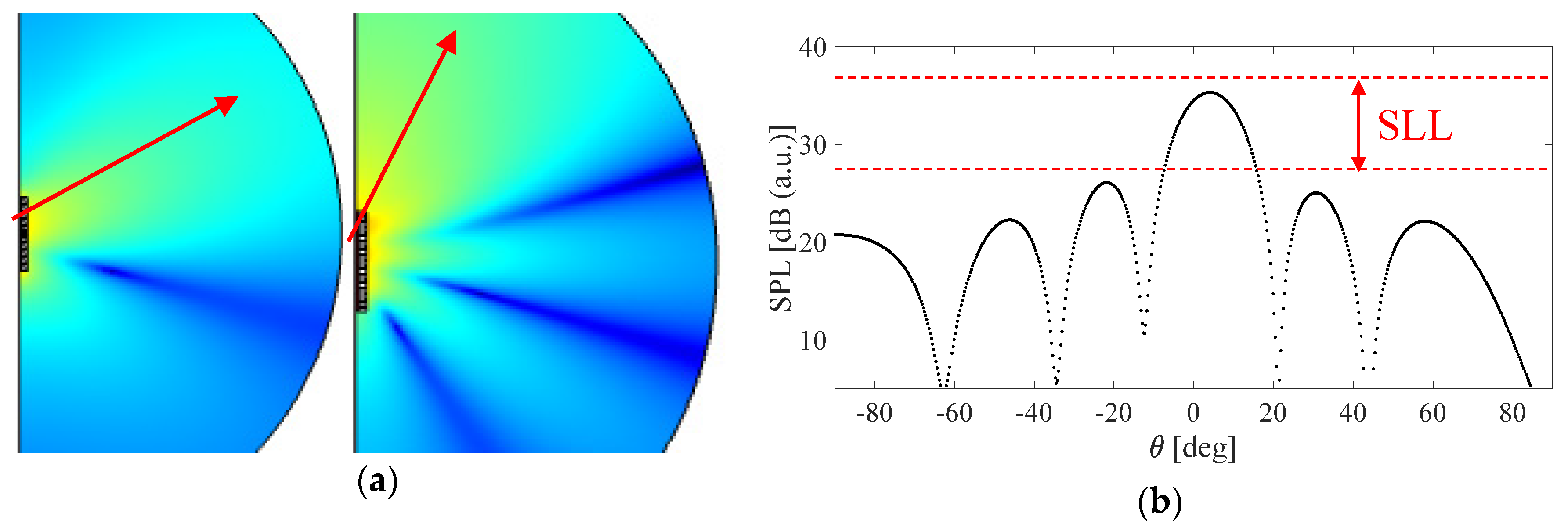
4.2. Side Lobe Level (SLL)
5. Conclusions
Author Contributions
Conflicts of Interest
References
- Naify, C.J.; Woolfe, K.; Layman, C.N.; Rogers, J.S.; Guild, M.D.; Orris, G. Designing beampatterns with tapered leaky wave antennas. J. Acoust. Soc. Am. 2017, 141, 3374. [Google Scholar] [CrossRef]
- Naify, C.J.; Layman, C.; Martin, T.P.; Nicholas, M.; Calvo, D.C.; Oriss, G.J. Experimental realization of a variable index transmission line metamaterial as an acoustic leaky-wave antenna. Appl. Phys. Lett. 2013, 102, 20. [Google Scholar] [CrossRef]
- Esfahlani, S.H.S.; Karkar, S.; Lissek, H. Optimization of an acoustic leaky-wave antenna based on acoustic metamaterial. In Proceedings of the Acoustics 2013, New Delhi, India, 10–15 November 2013. [Google Scholar]
- Naify, C.J.; Rogers, J.S.; Guild, M.D.; Rohde, C.A.; Orris, G.J. Evaluation of the resolution of a metamaterial acoustic leaky wave antenna. J. Acoust. Soc. Am. 2016, 139, 3251. [Google Scholar] [CrossRef] [PubMed]
- Lim, S.; Caloz, C.; Itoh, T. Metamaterial-based electronically controlled transmission-line structure as a novel leaky-wave antenna with tunable radiation angle and beamwidth. IEEE Trans. Microw. Theory Tech. 2004, 52, 2678–2690. [Google Scholar] [CrossRef]
- Jackson, D.R.; Caloz, C.; Itoh, T. Leaky-Wave Antennas. Proc. IEEE 2012, 100, 2194–2206. [Google Scholar] [CrossRef]
- Liu, J.; Zhou, W.; Long, Y. A Simple Technique for Open-Stopband Suppression in Periodic Leaky-Wave Antennas Using Two Nonidentical Elements Per Unit Cell. IEEE Trans. Antennas Propag. 2018, 66, 2741–2751. [Google Scholar] [CrossRef]
- Esfahlani, H.; Karkar, S.; Lissek, H.; Mosig, J.R. Exploiting the leaky-wave properties of transmission-line metamaterials for single-microphone direction finding. J. Acoust. Soc. Am. 2016, 139, 3259. [Google Scholar] [CrossRef] [PubMed]
- Poveda-García, M.; Cañete-Rebenaque, D.; Gómez-Tornero, J.L. Frequency-Scanned Monopulse Pattern Synthesis Using Leaky-Wave Antennas for Enhanced Power-Based Direction-of-Arrival Estimation. IEEE Trans. Antennas Propag. 2019, 67, 7071–7086. [Google Scholar] [CrossRef]
- Poveda-García, M.; Gómez-Alcaraz, A.; Cañete-Rebenaque, D.; Martinez-Sala, A.S.; Gómez-Tornero, J.L. RSSI-Based Direction-of-Departure Estimation in Bluetooth Low Energy Using an Array of Frequency-Steered Leaky-Wave Antennas. IEEE Access 2020, 8, 9380–9394. [Google Scholar] [CrossRef]
- Gómez-Tornero, J.L. Unusual tapering of leaky-wave radiators and their applications. In Proceedings of the 5th European Conference on Antennas and Propagation (EUCAP), Rome, Italy, 11–15 April 2011. [Google Scholar]


Publisher’s Note: MDPI stays neutral with regard to jurisdictional claims in published maps and institutional affiliations. |
© 2020 by the authors. Licensee MDPI, Basel, Switzerland. This article is an open access article distributed under the terms and conditions of the Creative Commons Attribution (CC BY) license (https://creativecommons.org/licenses/by/4.0/).
Share and Cite
Felis-Enguix, I.; Otero-Vega, J.; Campo-Valera, M.; Villó-Pérez, I.; Gómez-Tornero, J.L. Practical Aspects of Acoustic Leaky-Wave Antennas Applied to Underwater Direction Finding. Eng. Proc. 2020, 2, 93. https://0-doi-org.brum.beds.ac.uk/10.3390/ecsa-7-08218
Felis-Enguix I, Otero-Vega J, Campo-Valera M, Villó-Pérez I, Gómez-Tornero JL. Practical Aspects of Acoustic Leaky-Wave Antennas Applied to Underwater Direction Finding. Engineering Proceedings. 2020; 2(1):93. https://0-doi-org.brum.beds.ac.uk/10.3390/ecsa-7-08218
Chicago/Turabian StyleFelis-Enguix, Ivan, Jorge Otero-Vega, María Campo-Valera, I. Villó-Pérez, and J. L. Gómez-Tornero. 2020. "Practical Aspects of Acoustic Leaky-Wave Antennas Applied to Underwater Direction Finding" Engineering Proceedings 2, no. 1: 93. https://0-doi-org.brum.beds.ac.uk/10.3390/ecsa-7-08218