
Influence of Structural Heterogeneity of High-Strength OCTG Tubes on Sulfide Corrosion Cracking Resistance †

Abstract
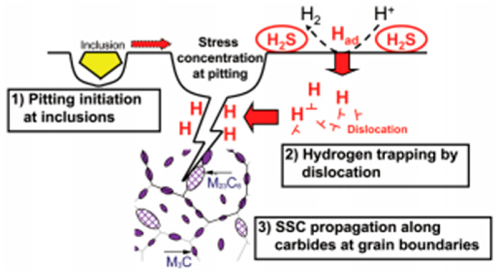
:1. Introduction
2. Materials and Research Methods
3. Results
3.1. Mechanical Properties
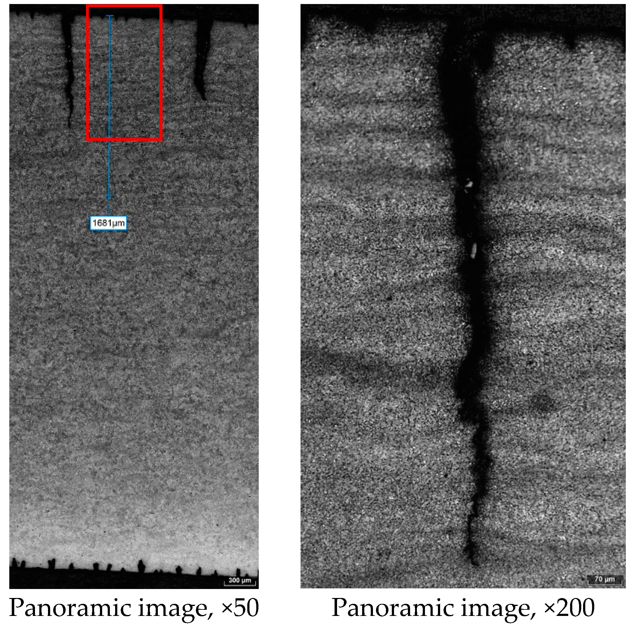
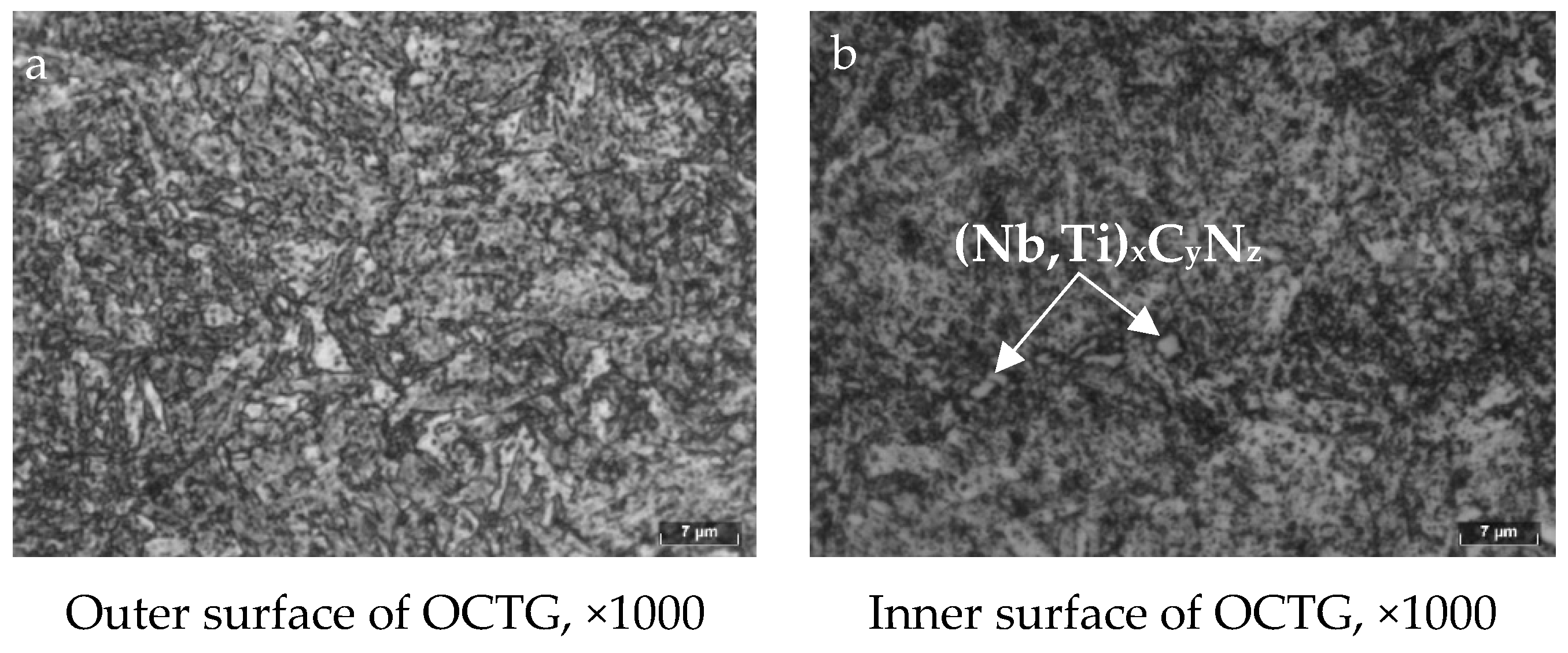
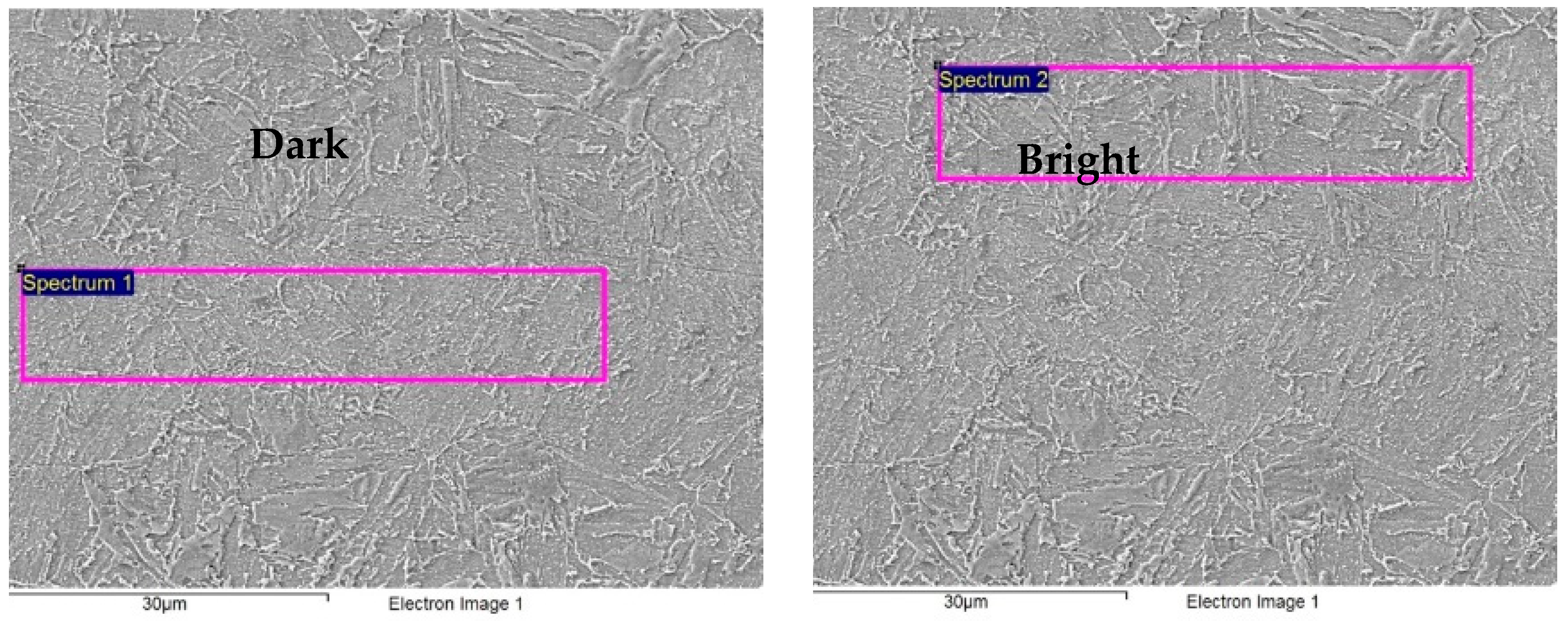
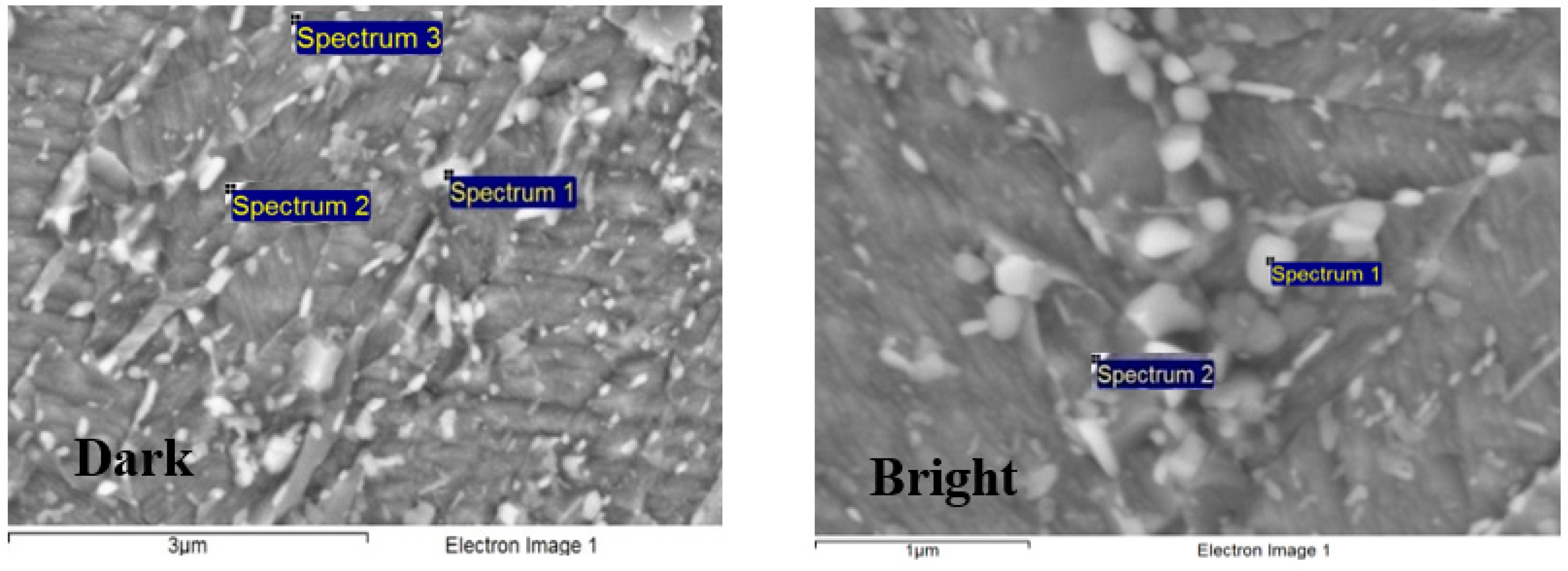
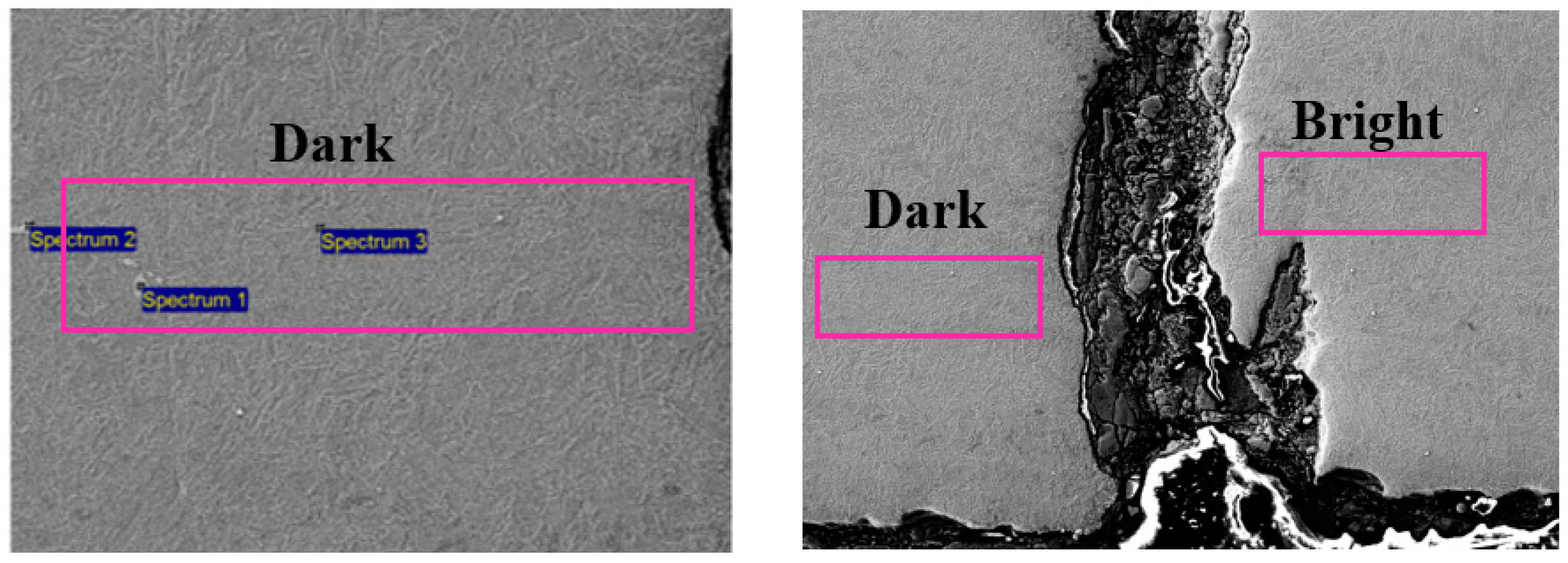
3.2. Metallographic Analysis
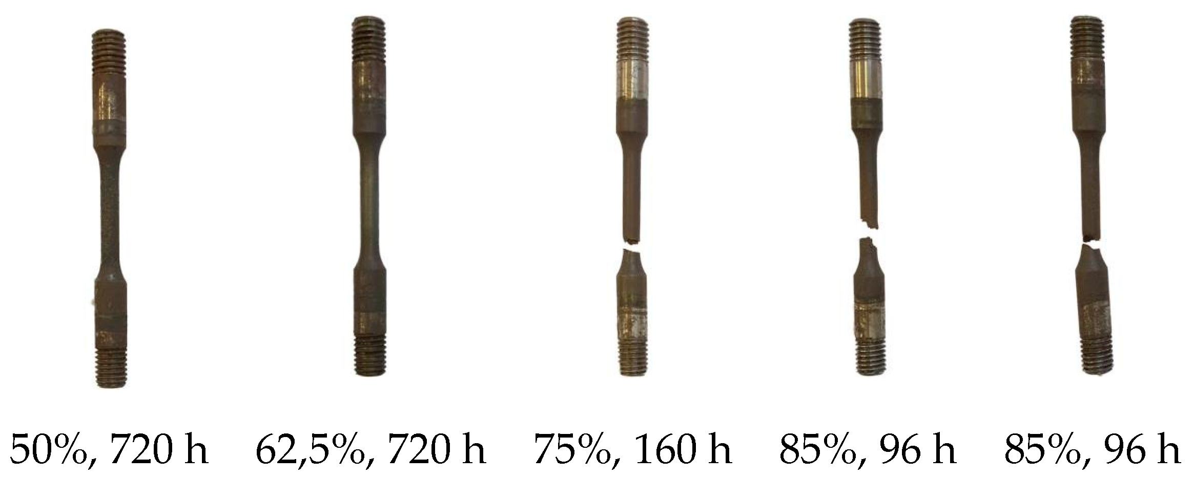
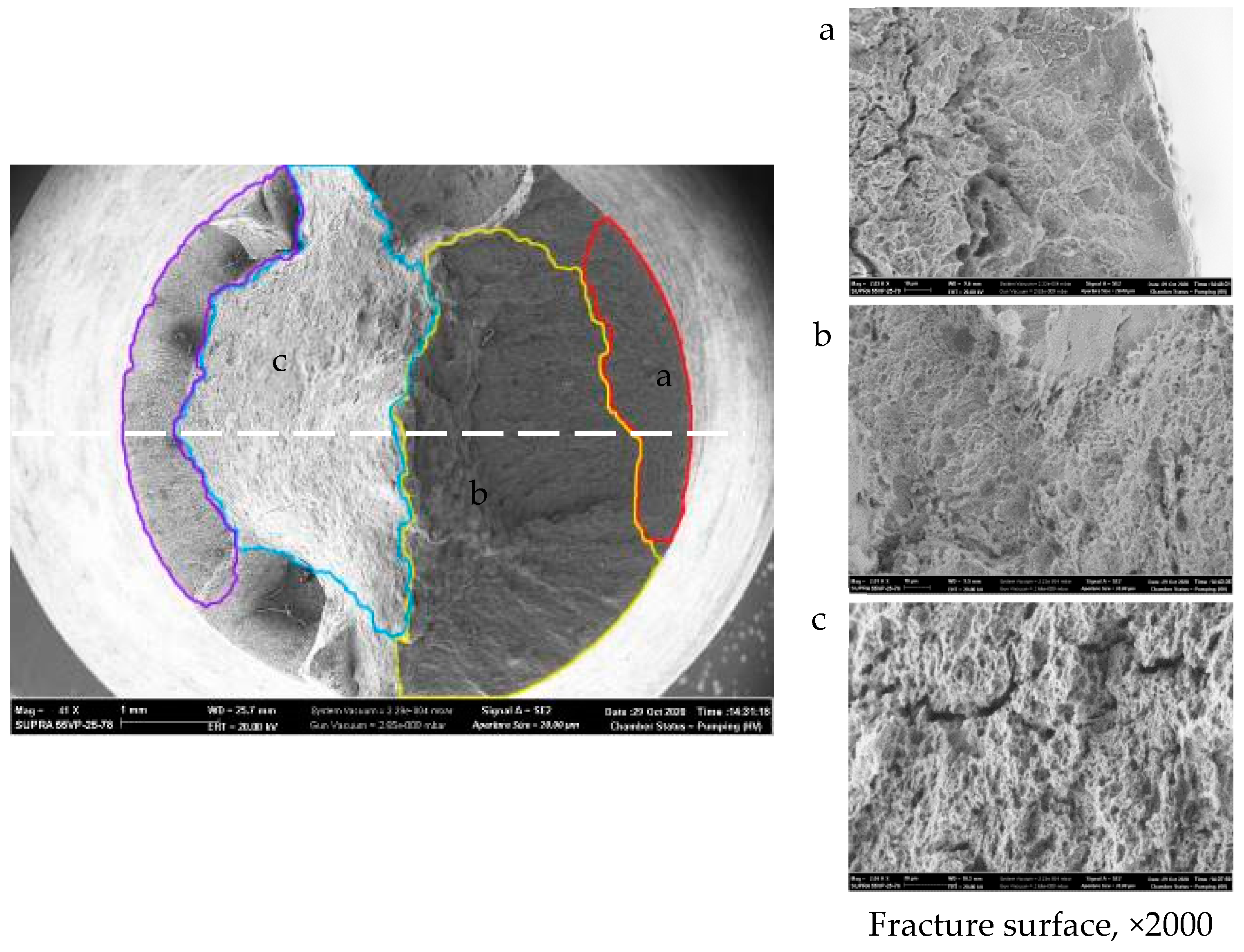
3.3. SSRT Testing
4. Conclusions
Funding
Informed Consent Statement
References
- Kostitsyna, I.; Shakhmatov, A.; Davydov, A. Study of corrosion behavior of carbon and low-alloy steels in CO2-containing environments. In Proceedings of the E3S Web Conferences, Saint Petersburg, Russia, 15–17 September 2021; Volume 121, p. 04006. [Google Scholar] [CrossRef]
- Strekalovskaya, D.A.; Davydov, A.D.; Lyashenko, D.V.; Tleshev, M. Failure analysis of plunger rod and barrel of sucker rod pumps. IJMPERD 2020, 10, 14835–14844. [Google Scholar] [CrossRef]
- Devyaterikova, N.; Nurmukhametova, M.; Kharlashin, A.; Popov, Y. Types of corrosion damage of tubing in the oilfield. In Proceedings of the E3S Web of Conferences, Saint Petersburg, Russia, 22–24 May 2019; Volume 121, p. 03001. [Google Scholar]
- Ermakov, B.S.; Alhimenko, A.A.; Shaposhnikov, N.O.; Tsvetkov, A.S.; Shirokov, A.V. Study of the crystallographic texture of pipe steel. Lett. Mater. 2020, 10, 48–53. [Google Scholar] [CrossRef]
- Alkhimenko, A.; Ermakov, B.; Alekseeva, E.; Mushnikova, S. Peculiarities of corrosion cracking of high-strength pipe steels in hydrogen sulfide environment. Int. J. Mech. Prod. Eng. Res. Dev. (IJMPERD) 2020, 10, 15175–15184. Available online: http://www.tjprc.org/publishpapers/2-67-1601123912-IJMPERDJUN20201446.pdf (accessed on 1 September 2020). [CrossRef]
- Aleksandrov, S.; Laev, K.; Shcherbakov, I.; Devyaterikova, N.; Oshurkov, G.; Rogova, K.; Pavlov, A.; Rodionova, I. Hot-rolled Seamless Tubing with Increased Operational Reliability for Oil-Field. Equipment. Patent RU 2719618 C1, 21 April 2020. [Google Scholar]
- ANSI/API Specification 5CT «Specification for Casing and Tubing». Available online: https://www.api.org/~/media/Files/Certification/Monogram-APIQR/Purchasing%20Guidelines/5CT%209th%20Edition%20Purch%20Guidelines%20R1%2020120429.pdf (accessed on 1 September 2020).
- Shiryaeva, A.G.; Chetverikovb, S.G.; Chikalova, S.G.; Pyshmintsevc, I.Y.; Krylovd, P.V. Production of Seamless Steel Pipe for Oil and Gas Extractionin Challenging Conditions. Steel Transl. 2018, 48, 704–711. [Google Scholar] [CrossRef]
- Zhou, T.; Zhang, P.; Kuuskman, K.; Cerilli, E.; Rehman, K.; Cho, S.; Burella, D. Development of Medium-High Carbon Casing/Tubing for Direct Strip Production Complex (DSPC). In Proceedings of the Materials Science and Technology 2016 (MS&T16) Salt Palace Convention Center, Salt Lake City, UT, USA, 23–27 October 2016; Volume 1, pp. 769–776. [Google Scholar]
- Putilova, E.A.; Zadvorkin, S.M.; Gorkunov, E.S.; Veselov, I.N.; Pyshmintsev, I.Y. Investigation of structure and properties of low-carbon low-alloyed Cr-Mo pipe steel intended for operating in sour environment. AIP Conf. Proc. 2019, 2167, 020291. [Google Scholar]
- Omura, T.; Numata, M.; Takayama, T.; Arai, Y. Super-high Strength Low Alloy Steel OCTG with Improved Sour Resistance. Nippon Steel & Sumitomo Metal Technical Report No. 107 February 2015. Ferrum Bull. Iron Steel Inst. Japan 2015, 9, 575–579. [Google Scholar]
- Trends in Oil and Gas Corrosion Research and Technologies; Pitting Corrosion 28; Sankara Papavinasam CorrMagnet Consulting Inc.: Ottawa, ON, Canada, 2017.
- Popoola, L.T.; Grema, A.S.; Latinwo, G.K.; Gutti, B.; Balogun, A.S. Corrosion problems during oil and gas production and its mitigation. Int. J. Ind. Chem. 2013, 4, 1–15. [Google Scholar] [CrossRef]
- Alhimenko, A.; Kharkov, A.; Shemyakinskiy, B.; Shaposhnikov, N. Development of the methodology of accelerated testing of oil-gas pipe steels for stress corrosion cracking 2020 Zavodskaya Laboratroiya. Diagn. Mater. 2020, 86, 70–76. [Google Scholar]
- NACE TM 0177 Laboratory Testing of Metals for Resistance to Sulfide Stress Cracking and Stress Corrosion Cracking in H2S Environments. Available online: https://store.nace.org/tm0177-2016 (accessed on 1 September 2020).
- GOST 1497-84 Metals. Methods of Tension Test. Available online: https://docs.cntd.ru/document/1200004888 (accessed on 1 September 2020).


| Sample | YS, MPa | TS, MPa | Elongation, % | YS/TS | Hardness, HRC |
|---|---|---|---|---|---|
| 1 | 795 | 878 | 18.7 | 0.90 | 26.0 |
| 2 | 785 | 875 | 19.1 | 0.89 | 26.5 |
| 3 | 800 | 880 | 20.1 | 0.90 | 26.0 |
| GOST 31446 | 758–828 | >793 | 18.0 | 0.86 | <30.0 |
| Element | Dark Band | Bright Band |
|---|---|---|
| Spectrum 1 | Spectrum 2 | |
| Si | 0.42 | 0.32 |
| Cr | 1.29 | 0.96 |
| Mn | 0.88 | 0.93 |
| Fe | 95.99 | 97.07 |
| Mo | 1.42 | 0.71 |
| Element | Dark Band | Bright Band | ||||
|---|---|---|---|---|---|---|
| Spectrum 1 | Spectrum 2 | Spectrum 3 | Spectrum 1 | Spectrum 2 | ||
| Cr | 3.18 | 3.41 | 1.55 | 3.79 | 6.80 | |
| Mn | 1.77 | 1.98 | 0.96 | 2.34 | 4.35 | |
| Mo | 3.02 | 2.01 | – | 2.27 | 3.23 | |
| Fe | 92.03 | 92.14 | 96.39 | 91.18 | 84.24 | |
| Ti | – | – | – | – | 1.00 | |
| Element | Spectrum 1 | Spectrum 2 | Spectrum 3 |
|---|---|---|---|
| Ti | 1.12 | 1.12 | – |
| Fe | 5.76 | 7.31 | 95.13 |
| Nb | 93.12 | 91.57 | – |
| Si | – | – | 0.45 |
| Cr | – | – | 0.91 |
Publisher’s Note: MDPI stays neutral with regard to jurisdictional claims in published maps and institutional affiliations. |
© 2021 by the authors. Licensee MDPI, Basel, Switzerland. This article is an open access article distributed under the terms and conditions of the Creative Commons Attribution (CC BY) license (https://creativecommons.org/licenses/by/4.0/).
Share and Cite
Davydov, A.; Zhitenev, A.; Devyaterikova, N.; Laev, K. Influence of Structural Heterogeneity of High-Strength OCTG Tubes on Sulfide Corrosion Cracking Resistance. Mater. Proc. 2021, 3, 5. https://0-doi-org.brum.beds.ac.uk/10.3390/IEC2M-09386
Davydov A, Zhitenev A, Devyaterikova N, Laev K. Influence of Structural Heterogeneity of High-Strength OCTG Tubes on Sulfide Corrosion Cracking Resistance. Materials Proceedings. 2021; 3(1):5. https://0-doi-org.brum.beds.ac.uk/10.3390/IEC2M-09386
Chicago/Turabian StyleDavydov, Artem, Andrey Zhitenev, Natalya Devyaterikova, and Konstantin Laev. 2021. "Influence of Structural Heterogeneity of High-Strength OCTG Tubes on Sulfide Corrosion Cracking Resistance" Materials Proceedings 3, no. 1: 5. https://0-doi-org.brum.beds.ac.uk/10.3390/IEC2M-09386