Effect of the Conductor Positioning on Low-Power Current Transformers: Inputs for the Next IEC 61869-10


Department of Electrical, Electronic and Information Engineering, Guglielmo Marconi Alma Mater Studiorum, University of Bologna, Viale del Risorgimento 2, 40136 Bologna, Italy
*
Author to whom correspondence should be addressed.
Electricity 2021, 2(1), 1-12; https://0-doi-org.brum.beds.ac.uk/10.3390/electricity2010001
Submission received: 8 October 2020
/
Revised: 17 November 2020
/
Accepted: 2 December 2020
/
Published: 5 January 2021
(This article belongs to the Special Issue Electromagnetic Compatibility in Power Systems and Smart Cities)
Abstract
:Low-power instrument transformers (LPITs) are spreading among the distribution network thanks to their features (e.g., compactness, lightness, enhanced bandwidth, etc.). It is then a fundamental to guide users and manufacturers to a correct usage and manufacturing of the LPITs. Technical committees, which are in charge of writing dedicated standards, often tackle such a task. Focusing on the current type of LPITs, the low-power current transformers (LPCTs), the associated standard is the IEC 61869-10, which is going to be improved in 2021. To this purpose, the work aims at providing new inputs for the future version of such a standard. In particular, the focus is pointed towards the effects of the conductor positioning on the window-type LPCT accuracy. Literature and gained experience in the field are the two pillars that have been used to refine the outcomes of the work, which are provided in terms of suggestions for each technical aspect, as discussed in the standard, related to LPCTs.
Keywords:
low-power current transformer; standard; accuracy; uncertainty; tests; guidelines; position1. Introduction
The digitalization of the power grid requires that all existing electric assets adapt themselves to a new concept of grid [1,2,3,4]. As a matter of fact, the possibility of monitoring and actively controlling the entire network opens a completely different scenario of opportunities for experts and system operators (SO), which includes a variety of algorithms and artificial intelligence-based software [5,6,7,8,9].
From the measurement perspective, the digitalization results in two possible solutions: (i) the development of intelligent electronic devices (IEDs) to be connected to existing instrument transformers (ITs); (ii) the development of a new generation of ITs that answer to the incoming needs.
Both ways have been studied and tackled in the last decades. On the one hand, the former solution led to the development of innovative devices, like smart meters, phasor measurement units (PMUs) [10,11], and stand-alone merging units (SAMUs) [12,13], which are directly connectable to the conventional current and voltage transformers (CT and VTs). On the other hand, the so-called low-power instrument transformers (LPITs) or non-conventional instrument transformers (NCITs) have been developed to face issues that are related to the emerging Smart Grids.
As far as the transmission network is concerned, the first solution is the typically implemented one. In fact, the high economic availability allows for transmission system operators (TSOs) to invest on accurate and expensive metering devices to be included in the measurement chain, without the need for replacing the existing ones. However, the distribution network, when considering its mashed and highly node-populated structure, cannot rely on the same budget per node ratio to invest in new technologies. Therefore, innovative and low-cost solutions, like LPITs, are the key to implementing a wide area monitoring system in medium and low voltage networks (MV and LV, respectively).
In light of the significance of the introduced topic, this work deals with ITs and, in particular, with low-power current transformers (LPCTs). In particular, the focus is pointed towards the standards that are associated with them, the IEC 61869 series. Such series consists of two general documents, one for the ITs, the IEC 61869-1 [14], and one for the LPITs, the IEC 61869-6 [15]. They contain general requirements, tests, and definitions, to be followed by manufacturers and final users, which apply to all types of transformers. Afterwards, the IEC 61869 series continues with one document for each specific transformer (current, voltage, combined, etc.) and, when considering the topic of the work, it is worth mentioning the IEC 61869-10 and -11 for the LPCT and low-power voltage transformers (LPVTs) [16,17], respectively.
The standardization work for ITs is crucial to cover and deal with all their feature and operating conditions, either normal or special. For example, lots of studies try to assess and improve IT accuracy [18,19,20,21,22,23]. Instead, another pillar is the effect of external influence quantities on the operation of ITs. For instance, [24,25,26,27] deal with the effect of temperature on ITs, while [28] studies the effect of moisture. Finally, electromagnetic compatibility, frequency, and positioning issues are discussed in [29,30,31,32,33,34,35].
Therefore, this work aims at contributing to the standards improvement, providing inputs to the future version of the IEC 61869-10, which is expected for 2021. Of course, reviewing an entire standard would be extremely long and complicate; hence, the focus is pointed on Annex D of [16], which deals with window-type LPCTs. In what follows, experience that is gained during the years and from in-field measurement campaigns plus the current and conspicuous available literature have been used in order to provide to the reader a set of comments helpful for the standard improvement. Furthermore, what can be considered the second aim of the work is to provide a practical and realistic point of view to those who write the standards. In fact, a well-written standard should match, for each aspect, the need of standardization and its real implementation.
2. Low-Power Current Transformers
2.1. Introduction
By definition, a current or voltage LPIT is an “arrangement, consisting of one or more current or voltage transformer(s) which may be connected to transmitting systems and secondary converters, all intended to transmit a low-power analogue or digital output signal to measuring instruments, meters and protective or control devices or similar apparatus” [15]. Therefore, the main difference with a conventional IT is essentially the secondary output level.
In terms of aim, an LPCT can either be of the measurement or of the protective purpose type. Of course, the measurement purpose is demanded to be accurate and reliable in all operating conditions; while a protective purpose LPCT should correctly operate, even without high level of accuracy, when the grid experiences faulty conditions. In particular, the LPCT must be fast enough to communicate the danger condition to the relays of the network, which will open and extinguish the fault.
A second classification of LPCTs differentiate themselves as electronic and passive. In detail, an electronic LPCT includes active components that supply it and it may condition the measured signal, which makes it suitable for the data collector or any other subsequent device of the measurement chain. On the other end, a passive LPCT is completely independent of an external supply and it is fully operational by itself. Therefore, the only signal conditioning is performed by the internal technology of the LPCT and not by any additional active components.
Turning to an operating principle classification, three main type of LPCTs can be found: Rogowski coils (or derivative), iron core (or proportional), and optical. The first two categories are going to be better described in Section 2.2 and Section 2.3, respectively, because they can both be built with the window-type technology (the conductor can be inserted, and it is not integrated into the LPCT).
Before moving to those sections, another topic that pools together all kinds of LPCTs has to be described: the accuracy. In fact, the accuracy that is associated to a measurement is fundamental to have an estimate of how well the device is measuring/performing. First of all, three main indices are used in order to evaluate the LPCTs uncertainty: the ratio error , the phase displacement , and the composite error , which are, respectively, defined as:
where is the rated transformation ratio of the LPCT, and are the rms values of the secondary and the primary quantities, and and their phase angles, respectively. In addition, in Equation (3), is the duration of one cycle, and are the instantaneous primary and secondary quantities, and is the rated delay time. Generally, and are used for measuring purpose LPCTs, while for the protective purpose ones.
Afterwards, the standards [14,15] provide a series of tables in which several accuracy classes are defined for both measuring and protective LPCTs. To each accuracy class (AC) corresponds two limits, one for and one for . For example, the AC 0.5 has limits 0.5 % for and 9 mrad for . Therefore, an LPCT that belongs to the AC 0.5 operates within such limits, but over those of the previous (stricter) AC.
2.2. Rogowski Coils
A Rogowski coil, or derivative LPCT, is a current transformer that operates according to the same magnetic properties of a conventional iron-core CT, with the difference that it is wound over a non-magnetic core (which could be either air or any insulating material). The peculiarity of not having an iron-core makes the Rogowski coil linear over a very wide range of currents; in fact, its core cannot saturate as a conventional CT. However, the lack of iron results in a lower mutual inductance between the primary and secondary windings. Therefore, the Rogowski output signal is very weak (hence, low-power) and it is capable of only driving microprocessor-based devices.
The operating principle of a Rogowski coil can be described by looking at Figure 1 and from its expression:
In fact, the instantaneous output voltage is proportional to the derivative of the primary current , which is flowing inside the conductor that is inserted into the Rogowski window. Furthermore, is also directly proportional to the mutual inductance and almost 90° with respect to . In Figure 1, it can be distinguished the cross-section of the non-magnetic core and the radius of the Rogowski window.
Turning to the equivalent circuit of the Rogowski coil, it is presented in Figure 2. The circuit contains, on the secondary side, an inductor , a resistor , a capacitor , and a burden . is the cause of the aforementioned deviation from the 90° shift between and (even if quite small). All of the windings contribute, and losses are summarized with , while the stray capacitances and conductors’ capacitance are schematized with . The presence of is typically neglected for the power–frequency, metering applications. Finally, is a high impedance burden that is highly recommended by [15] to be connected to the secondary terminals of the Rogowski coil. Regarding it represents the rms magnitude of .
The importance of having an equivalent circuit as much accurate as possible is due to the direct link between its parameters and the accuracy relations expressed in Equations (1) and (2). In fact, neglecting , , and can be written in terms of and , as:
where and is the grid operating frequency.
2.3. Iron-Core Current Transformers
An iron-core, or proportional LPCT, is a very simple current transformer that provides an output voltage that is proportional to the primary current. Figure 3 depicts its working principle. In it, the primary and secondary windings and , respectively, a shunt resistor , and the burden can be distinguished. It is worth highlighting that is an integral part of the LPCT, and not an external additional component.
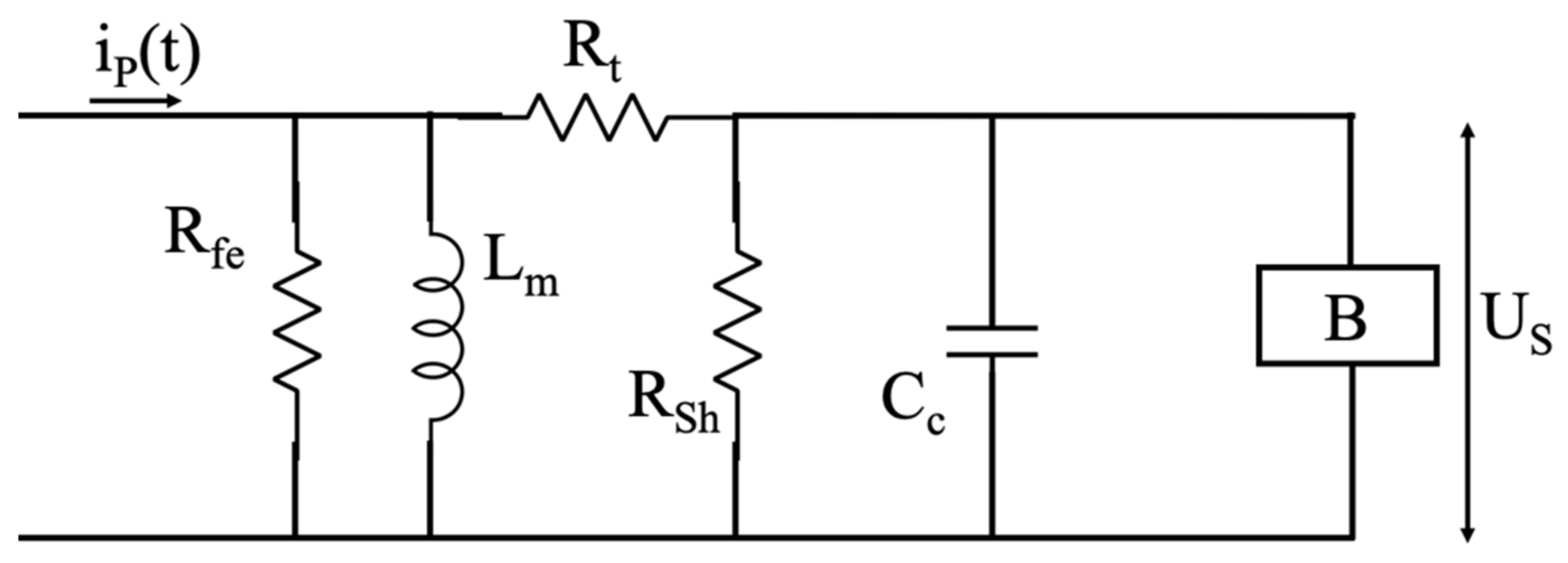
Increasing the level of detail, the equivalent circuit of an iron-core LPCT is shown in Figure 4. In the picture, in addition to the components that are introduced in Figure 3, there are the core parameters and to represent the iron losses and magnetizing inductance, respectively, the resistance of the windings , and the equivalent capacitance of the conductors .
Of course, being iron-core based, this kind of LPCT suffers from the same issues that affect a conventional CT (saturation, non-linearity, narrow bandwidth, etc.).
3. Standard IEC 61869-10
3.1. General Overview
IEC 61869-10 and the other documents of the standard series have the same structure. In particular, one chapter is dedicated to the definitions that are helpful for understanding the concepts within the document. For example, output signal, ratio error, composite error, and all accuracy indexes can be found. In addition, it is worth reminding that [16] considers both measuring and protective purpose LPCTs; hence, the definition and limits are provided for both categories of device.
A second chapter of [16] deals with the rated values. In it, the rated operating conditions are fixed for each aspect of an LPCT. Rated burden, accuracy class, limits of the errors, and suggested values for the primary and secondary quantities are just few examples.
When considering the context of this work, and for the sake of completeness, the above introduced rated primary current and secondary voltage specified in [16] are 25 A, 50 A, 80 A, and 100 A, and 22.5 mV, 150 mV, and 225 mV, respectively. At a glance, it is evident the small amplitude of the rated secondary outputs, which can be easily subjected to disturbances or any other external influence.
A third short chapter tackles some specification for the manufacturers. It includes the emission requirements, the terminal markings, and other suggestions on the conductors to be used and on the information that is to be specified to the final user.
The final chapter is the technical one; in fact, it presents the list of tests that must be performed on the LPCTs in order to be compliant with the standard. The tests are sorted into type tests and special tests. The former category includes temperature, electromagnetic compatibility, accuracy, and transient performance tests. Of course, the list of tests is being improved in each new version of [16], in order to be aligned with the current researches and findings in the field.
3.2. Annex D
The standard ends with four annexes (from A to D), which help the readers to have a complete comprehension of the LPCTs scenario. In fact, Annex A contains further information regarding how to approach LPCT accuracy; whereas, Annex B and C make a step back, reminding to the reader the working principles of the Rogowski coil and iron-core types of LPCT.
Turning to the main focus of this work, Annex D presents the details regarding how to perform the accuracy test with respect to the positioning of the primary (and then of the external) conductor. As a matter of fact, it is on this specific aspect of [16] that the authors are presenting new inputs to be considered for the next version of the standard planned for 2021.
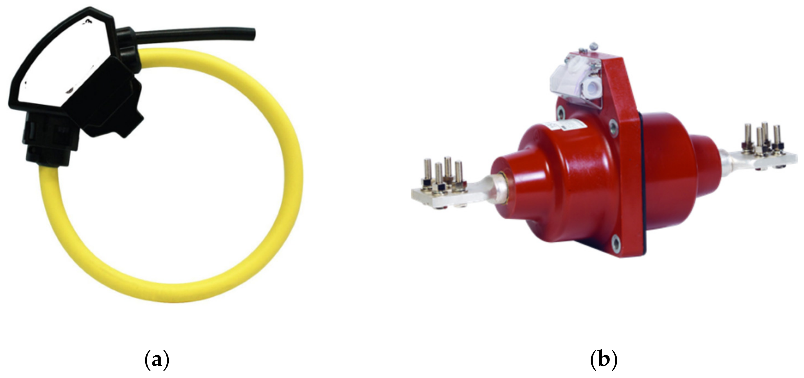
Annex D applies to all window-type (split-core or not) LPCTs without an integrated conductor (see Figure 5), because, for the bar-type LPCTs, the conductor positioning does not have an effect on LPCT accuracy.
Annex D then extends the accuracy class information of an LPCT, including a code that specifies how much the conductor positioning affects the device. By looking at Table 1, the codes A1 to A3 are associated to two different limits that are related to the conductor positioning: the power factor (PF) and the maximum angle.
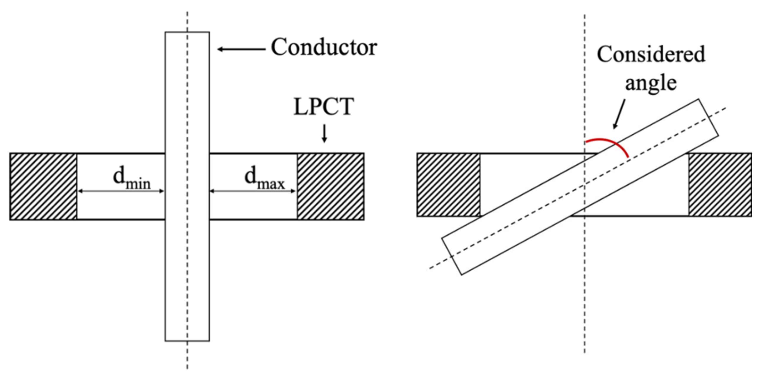
The PF is defined as
where and are two lengths that are defined as in Figure 6, which specify the distances between the conductor and the body of the LPCT. Therefore, a PF = 0 means that the primary conductor is perfectly centered with respect to the LPCT window, while a PF = 1 refers to a conductor that is adjacent to the inner part of the LPCT ( or equal to zero).
As for the angle, the considered one (hence, included in Table 1) starts from the window axe of the LPCT (see Figure 6). Therefore, an angle that is equal to 0 refers to a centered primary conductor; whereas, any other positive angle, means that the conductor is moving from its centered (ideal) position.
Hence, for the sake of clarity, if code A3 is associated to the accuracy class information of an LPCT, it means that such a class is guaranteed up to a PF = 1 and up to an angle of 45° between the primary conductor and LPCT axe. In other words, the code A1 is the strictest among the three, describing all those LPCTs which are extremely affected by the primary conductor positioning.
Finally, Annex D suggests that an accuracy test be performed on the LPCTs in order for them to be associated to a class of Table 1. Therefore, the test, once the code of Table 1 has been fixed as desired goal, consists of two steps: (i) an accuracy evaluation with the LPCT positioned at the PF defined by the code; (ii) a second accuracy evaluation with the LPCT positioned with the angle defined by the code. All of the tests have to be performed with a primary conductor having a diameter 0.2 times the diameter of the LPCT window.
In the next section, all of the presented aspects regarding Annex D are deeply analyzed and commented, providing suggestions and inputs for their improvement.
4. Discussion
This section is structured while considering the different aspects that are related to [16]. In detail, Section 4.1 assesses the geometrical issues that are associated to LPCTs; while Section 4.2 and Section 4.3 treat the influence of the primary and the external conductors. Finally, in Section 4.4, a market analysis is presented to support, with a practical point view, what discussed in this work.
4.1. Geometrical Issues
A first subject that has to be mentioned is the geometrical influence of LPCTs and of the primary conductor to the final performance of the device. The shape of the LPCT, which could be circular, oval, etc., varies its performance, as is clearly highlighted in [36,37]. Furthermore, the shape of the primary conductor makes a huge difference on the final behavior of an LPCT. For example, the rigidity of the busbar conductor, which is often installed in power plants, reduces the impact of the primary conductor positioning on the operation of an LPCT, compared to a typical cylindrical conductor. The results shown in [36] demonstrate that the mutual inductance of the LPCT decreases as much has the ratio between the coil radius and the busbar dimensions decreases (from 1 to 0.996 p.u.). Instead, in [37], it is confirmed how the output voltage of the LPCT is affected as much as the coil shape differs from a circle and it becomes oval (amplitude errors between 1% and 2%).
Even the diameter of the primary conductor plays an important role. As a matter fact, the thicker the conductor, the higher the discrepancies with an ideal, centered, and with negligible diameter conductor. However, the standard [16] suggests using the LPCTs with conductors having a diameter 0.2 times the diameter of the device window. Unfortunately, as also reported in [38], window-type LPCTs are often in-field implemented around high-section or even multiple conductors, which is quite far from the suggested good practice. In fact, the use of an LPCT that matches the conductor dimensions helps to reach the ideal centered position (see Section 4.2).
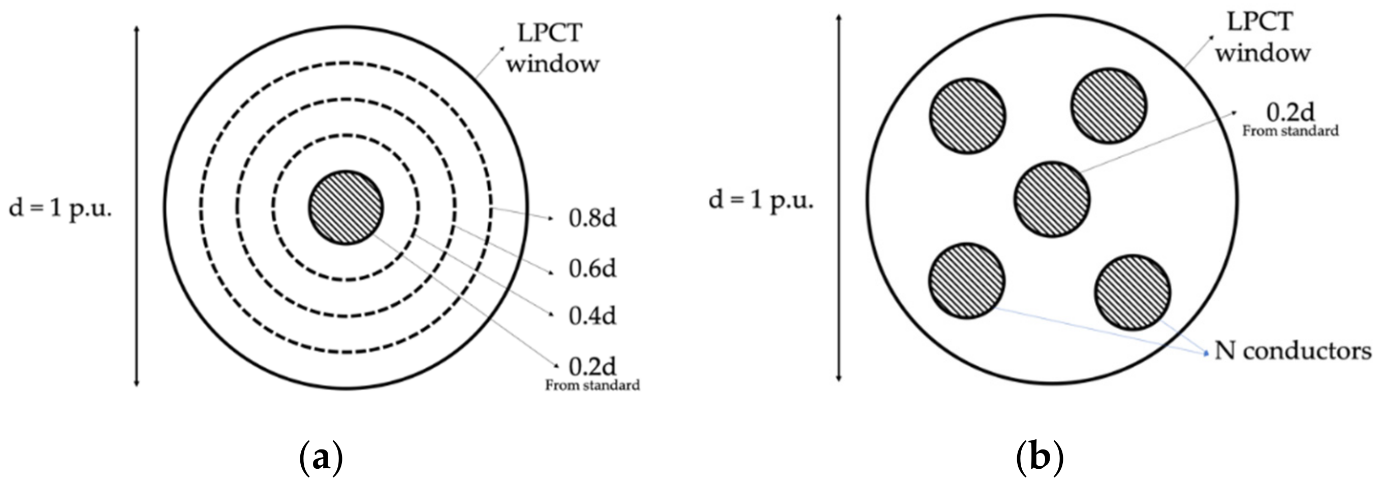
In light of the above, a potential input for [16] is to include a section, by means of the available literature, standardizing realistic tests and ways of implementing different LPCTS: with a single, but diameter varying, conductor, and with multiple conductors (see Figure 7). This way, the final user, or even the manufacturer, would be guided on the effect on the accuracy from different ways of using their devices.
4.2. Primary Conductor
The primary and the external conductor positioning can be considered among the main causes of performance degradation of an LPCT. In fact, from [31], it is clear how positions that are different from the centered one (see Figure 6) drastically change the LPCT behavior leading; in some cases, to exceed the accuracy class limits). In [31], a study has been presented in which several LPCTs have been tested in various positions. From the results, it emerged that each LPCT differently react to a particular position, but all of them were sensitive to at least one of the tested positions. Such sensitiveness made the accuracy of the LPCT increase up to 8% for the magnitude, while the phase error was not significantly affected. Of course, the position is not the unique influence factor affecting the performance of an LPCT; hence, it should be even more carefully considered and solved.
As has been described in Section 3.2, [16] prescribes a set of tests with specific positions between the primary conductor and the LPCT which results in an accuracy coding, as expressed by Table 1. However, such tests may be considered to be too difficult and complex to be performed by both final users and manufacturers. A confirmation of the statement can be found in [31,32,36,38], where quite complicated, extremely accurate setups have been developed to test LPCTs in a variety of mutual positions between the LPCT and the primary conductor. Even with those setups, it could be difficult to tests the angle prescribed by the standard and reported in Table 1. Furthermore, from the in-field experience and from the complexity of the network, it is rather impossible to place, or even measure, the positioning angle of an LPCT primary conductor. In [39], a not-in-field implementable setup that is dedicated to the angle influence is presented. It involves hand-crafted material, high level technology, and an overall setup that is impossible to standardize as “typical” for being used by all LPCTs final users. It is worth to add that the majority of the off-the-shelf LPCTs do not include any centering device that allows the user to center its position with respect to the primary conductor.
Therefore, thinking of a new classification of mutual positions or other solutions that better reflects the realistic applications may be of help in improving Table 1.
To this purpose, two possible solutions for improving [16] are provided here.
The first one consists of a two-steps process. First of all, the primary conductor is kept centered with respect to the LPCT; afterwards, a current measurement and an accuracy evaluation are performed. Second, the LPCT is placed in its final operating position (that may be completely different from the centered one) and the same current measurement is performed in order to obtain a sort of calibration coefficient that is to be used during the life cycle of the device.
The second solution is more practical, it consists of including in the LPCT set a sort of centering device which will guarantee the centered position of the primary conductor. Figure 8 and Figure 9 depict a couple of suggestions. In Figure 8, the LPCT is equipped with some elastic strip in order to force the conductor in the centered position. In Figure 9, instead, a soft filler is used in order to fill the air gap between the primary conductor and the LPCT. Both of the solutions are quite cheap and they can be easily implemented in the majority of practical situations.
Of course, the standard may list several options for the final users, detailing, in each of them, how to implement them and which kind of accuracy can be expected.
4.3. External and Returning Conductors
If the primary conductor position can be “easily” solved with some potential solutions, the returning or external conductor position is not something of straightforward solution (e.g., see [36,40]). The fact is that such conductors may be passing through small areas or substation boxes, where there is no chance of moving them from the LPCT. The authors in [40] clearly demonstrated that, depending on the external conductor position with respect to the coil, each turn of the LPCT coil is more or less affected by the external cable. From the results, they demonstrate that there could be a magnetic field intensity difference between one turn and another up to seven times.
Therefore, what can be considered by the standard is a double approach. The first, as presented in Section 4.2, could be a preliminary testing that assess the influence of the existing cables configuration, after an ideal condition measurement taken with the desired LPCT.
The second approach consists of asking the manufacturers to produce LPCTs with those precautions that make the LPCT independent of the magnetic field that is generated by conductors different from the primary one. An example for that is the double or the return winding solutions that are often adopted for Rogowski coils.
4.4. The Market Perspective
This section includes a market research that aims at understanding to which extend the manufacturers comply with the standard in order to support what presented above [16]. The results, as presented in Table 2, provide an interesting (even if not encouraging) scenario. In fact, among the seven manufacturers, listed from A to G for the sake of privacy (the aim is not to judge any manufacturer), only two specify which kind of primary conductor the user may adopt. All seven LPCTs manufacturers do not provide (i) the accuracy class coding of Table 1; (ii) any centering device (CD).
In light of the results, the first comment is that manufacturers hardly follow the standard and its Annex. However, such a behavior may contain the input for the next [16]. In fact, what is proposed may be too difficult or too unrealistic to be practically implemented. Therefore, the future IEC 61869-10 may be a huge opportunity to align the rigorous scientific prescriptions with the in-field perspective and technical limitations.
5. Conclusions
Technical committees and standards are crucial for the interface between the academic and the industrial worlds. The outcomes of their meetings are documents that tackle several aspects of a particular topic, guiding manufacturers and users that are involved in a particular field.
Therefore, this paper aims at contributing in that way, providing inputs and suggestions to a well-known standard, the IEC 61869-10, so that it does not lose the practical and implementable approach that it should maintain. It deals with low-power current transformers, and its Annex D includes specifications on the primary conductor positioning effect on the device performance.
To this purpose, this work focuses on that particular annex, providing both academic and in-field perspectives to produce comments and suggestions to every aspect covered by Annex D.
The outcomes of this work are intended to be an input for the future version of IEC 61869-10, as expected for 2021.
Author Contributions
Conceptualization, L.P.; methodology, R.T.; validation, A.M., R.T.; formal analysis, A.M.; investigation, A.M.; writing—original draft preparation, A.M.; writing—review and editing, R.T.; supervision, L.P. All authors have read and agreed to the published version of the manuscript.
Funding
This research received no external funding.
Data Availability Statement
The data presented in this study are available in the article.
Conflicts of Interest
The authors declare no conflict of interest.
References
- Canaan, B.; Colicchio, B.; Abdeslam, D.O. Microgrid cyber-security: Review and challenges toward resilience. Appl. Sci. 2020, 10, 5649. [Google Scholar] [CrossRef]
- De Dutta, S.; Prasad, R. Digitalization of global cities and the smart grid. Wirel. Pers. Commun. 2020, 113, 1385–1395. [Google Scholar] [CrossRef]
- Kupzog, F.; King, R.; Stefan, M. The role of IT in energy systems: The digital revolution as part of the problem or part of the solution. e i Elektrotechnik Inf. 2020, 137, 341–345. [Google Scholar] [CrossRef]
- Qi, B.; Yuan, Y.; Yang, Y.; Bu, Q.; Chen, J. Overview of smart substations. In IEC 61850-Based Smart Substations; Elsevier: Amsterdam, The Netherlands, 2019; pp. 1–24. [Google Scholar]
- Mingotti, A.; Peretto, L.; Tinarelli, R. A novel equivalent power network impedance approach for assessing the time reference in asynchronous measurements. In Proceedings of the 2017 IEEE International Instrumentation and Measurement Technology Conference (I2MTC), Turin, Italy, 22–25 May 2017; pp. 1–6. [Google Scholar]
- Mingotti, A.; Peretto, L.; Tinarelli, R. An equivalent synchronization for phasor measurements in power networks. In Proceedings of the 2017 IEEE International Workshop on Applied Measurements for Power Systems (AMPS), Liverpool, UK, 20–22 September 2017; pp. 1–5. [Google Scholar]
- Johansson, C.; Vanhoudt, D.; Brage, J.; Geysen, D. Real-time grid optimisation through digitalisation—Results of the STORM project. Energy Procedia 2018, 149, 246–255. [Google Scholar] [CrossRef]
- Monti, A.; Ponci, F.; Ferdowsi, M.; McKeever, P.; Lowen, A. Towards a new approach for electrical grid management: The role of the cloud. In Proceedings of the 2015 IEEE International Workshop on Measurements & Networking (M&N), Coimbra, Portugal, 12–13 October 2015; pp. 1–6. [Google Scholar]
- Neugebauer, T.; Wolgast, T.; Nieße, A. Dynamic inspection interval determination for efficient distribution grid asset-management. Energies 2020, 13, 3875. [Google Scholar] [CrossRef]
- Huang, Z.; Dagle, J. SynchroPhasor measurements: System architecture and performance evaluation in supporting wide-area applications. In Proceedings of the 2011 IEEE Power and Energy Society General Meeting, Detroit, MI, USA, 24–28 July 2011; pp. 1–3. [Google Scholar]
- Mohanta, D.K.; Murthy, C.; Roy, D.S. A brief review of phasor measurement units as sensors for smart grid. Electr. Power Compon. Syst. 2016, 44, 1–15. [Google Scholar] [CrossRef]
- Cipolletta, G.; Delle Femine, A.; Gallo, D.; Landi, C.; Luiso, M. Design approach for a stand alone merging unit. In Proceedings of the 16th IMEKO TC10 Conference 2019 “Testing, Diagnostics and Inspection as a Comprehensive Value Chain for Quality and Safety”, Berlin, Germany, 3–4 September 2019; pp. 107–112. [Google Scholar]
- Roux, L.; Qastalane, Z.; Leitloff, Y. Tests to assess 61850-9-2 based stand alone merging units for metering purposes. In Proceedings of the 13th International Conference on Development in Power System Protection 2016 (DPSP), Edinburg, UK, 7–10 March 2016; p. 5. [Google Scholar]
- IEC 61869-1: 2010. Instrument Transformers—Part 1: General Requirements; International Standardization Organization: Geneva, Switzerland, 2010.
- IEC 61869-6: 2016. Instrument Transformers—Part 6: Additional General Requirements for Low-Power Instrument Transformers; International Standardization Organization: Geneva, Switzerland, 2016.
- IEC 61869-10: 2018. Instrument Transformers—Part 10: Additional Requirements for Low-Power Passive Current Transformers; Inter-national Standardization Organization: Geneva, Switzerland, 2018.
- IEC 61869-11: 2018. Instrument Transformers—Part 11: Additional Requirements for Low-Power Passive Voltage Transformers; International Standardization Organization: Geneva, Switzerland, 2018.
- Mingotti, A.; Peretto, L.; Bartolomei, L.; Cavaliere, D.; Tinarelli, R. Are inductive current transformers performance really affected by actual distorted network conditions? An experimental case study. Sensors 2020, 20, 927. [Google Scholar] [CrossRef] [PubMed] [Green Version]
- Mingotti, A.; Peretto, L.; Tinarelli, R.; Yigit, K. Simplified approach to evaluate the combined uncertainty in measurement instruments for power systems. IEEE Trans. Instrum. Meas. 2017, 66, 2258–2265. [Google Scholar] [CrossRef] [Green Version]
- Santos, J.C.; De Sillos, A.C.; Nascimento, C.G.S. On-field instrument transformers calibration using optical current and voltage transformes. In Proceedings of the 2014 IEEE International Workshop on Applied Measurements for Power Systems Proceedings (AMPS), Aachen, Germany, 24–26 September 2014; pp. 1–5. [Google Scholar]
- Stiegler, R.; Meyer, J.; Kilter, J.; Konzelmann, S. Assessment of voltage instrument transformers accuracy for harmonic measurements in transmission systems. In Proceedings of the 2016 17th International Conference on Harmonics and Quality of Power (ICHQP), Belo Horizonte, Brazil, 16–19 October 2016; pp. 152–157. [Google Scholar]
- Tong, Y.; Liu, B.; Deng, X.; Wang, Y. The experimental study on the electronic instrument transformer harmonic accuracy. In Proceedings of the China International Conference on Electricity Distribution, Shenzhen, China, 23–26 September 2014; pp. 1136–1139. [Google Scholar]
- Zhou, F.; Jiang, C.; Lei, M.; Lin, F. Improved stepup method to determine the errors of voltage instrument transformer with high accuracy. IEEE Trans. Instrum. Meas. 2020, 69, 1308–1312. [Google Scholar] [CrossRef]
- Li, Z.; Du, Y.; Abu-Siada, A.; Li, Z.; Zhang, T. A new online temperature compensation technique for electronic instrument transformers. IEEE Access 2019, 7, 97614–97623. [Google Scholar] [CrossRef]
- Mingotti, A.; Pasini, G.; Peretto, L.; Tinarelli, R. Effect of temperature on the accuracy of inductive current trans-formers. In Proceedings of the 2018 IEEE International Instrumentation and Measurement Technology Conference: Discovering New Horizons in Instrumentation and Measurement, Houston, TX, USA, 14–17 May 2018; pp. 1–5. [Google Scholar]
- Sivan, V.; Robalino, D.M.; Mahajan, S.M. Measurement of temperature gradients inside a medium voltage current transformer. In Proceedings of the 2007 39th North American Power Symposium, Las Cruces, NM, USA, 30 September–2 October 2007; pp. 242–245. [Google Scholar]
- Wang, P.; Zhang, G.; Zhu, X.; Luo, C. Temperature characteristic analysis on electronic current transformer. Diangong Jishu Xuebao Trans. China Electrotech. Soc. 2007, 22, 60–64. [Google Scholar]
- Yan, Z.H.; Ren, X.; Ren, H.; Ding, W.D. Study on condensation of the moisture in current transformers with current flow considering sharp temperature decrease. Appl. Mech. Mater. 2012, 322–327. [Google Scholar] [CrossRef]
- Marinescu, A.; Coatu, S.; Rucinschi, D. About the EMC of non-conventional electronic instrument transformer case study. In Proceedings of the 2012 International Conference on Applied and Theoretical Electricity (ICATE), Craiova, Romania, 25–27 October 2012; pp. 1–5. [Google Scholar]
- Peretto, L.; Sandrolini, L.; Tinarelli, R. Effects of radiated electromagnetic fields on measurements performed by air-core passive LPCTs. In Proceedings of the 2015 IEEE International Workshop on Applied Measurements for Power Systems (AMPS), Aachen, Germany, 23–25 September 2015; pp. 150–154. [Google Scholar]
- Mingotti, A.; Peretto, L.; Tinarelli, R. Effects of multiple influence quantities on Rogowski-coil-type current transformers. IEEE Trans. Instrum. Meas. 2020, 69, 4827–4834. [Google Scholar] [CrossRef]
- Hagmann, M.J. Method to calculate the positional sensitivity of a Rogowski coil. In Proceedings of the 2011 IEEE International Symposium on Electromagnetic Compatibility, Long Beach, CA, USA, 4–19 August 2011; pp. 318–322. [Google Scholar] [CrossRef]
- Oganyan, R.; Lankin, M.; Gorbatenko, N. Research of the effect of displacement primary winding of a measuring current transformer based on the Rogowski coil on the EMF of secondary winding. In Proceedings of the 2020 International Conference on Industrial Engineering, Applications and Manufacturing (ICIEAM), Sochi, Russia, 18–22 May 2020; pp. 1–5. [Google Scholar]
- Patel, T.P.; Singhal, S. FE based eccentricity analysis of Rogowski Coil. In Proceedings of the 2016 IEEE 1st International Conference on Power Electronics, Intelligent Control and Energy Systems (ICPEICES), Delhi, India, 4–6 July 2016; pp. 1–6. [Google Scholar]
- Xu, M.; Yan, J.; Geng, Y.; Zhang, K.; Sun, C. Research on the factors influencing the measurement errors of the discrete Rogowski coil. Sensors 2018, 18, 847. [Google Scholar] [CrossRef] [PubMed] [Green Version]
- Chiampi, M.; Crotti, G.; Morando, A. Evaluation of flexible Rogowski coil performances in power frequency applications. IEEE Trans. Instrum. Meas. 2011, 60, 854–862. [Google Scholar] [CrossRef]
- Lee, K.; Park, J.; Kang, S.; Lee, Y.; Ham, G.; Jang, Y.; Lim, K. Geometrical effects in the current measurement by Rogowski sensor. In Proceedings of the International Symposium on Electrical Insulating Materials, Himeji, Japan, 22–22 November 2001; pp. 419–422. [Google Scholar]
- Kojovic, L.A.; Bishop, M.T. Comparative characteristics of iron-core current transformers and Rogowski Coils for applications for protective relaying purposes. In Proceedings of the 2009 62nd Annual Conference for Protective Relay Engineers, College Station, TX, USA, 30 March–2 April 2009; pp. 527–535. [Google Scholar]
- Marracci, M.; Tellini, B.; Zappacosta, C.; Robles, G. Critical parameters for mutual inductance between Rogowski coil and primary conductor. IEEE Trans. Instrum. Meas. 2011, 60, 625–632. [Google Scholar] [CrossRef]
- Artero, J.; Arcega, F. Influence of external currents in sensors based on PCB Rogowski coils. Renew. Energy Power Qual. J. 2005, 1, 277–280. [Google Scholar] [CrossRef]
Figure 1.
Schematic of the Rogowski coil operating principle.

Figure 2.
Equivalent circuit of the Rogowski coil.

Figure 3.
Schematic of the operating principle of an iron-core low-power current transformer (LPCT).
Figure 3.
Schematic of the operating principle of an iron-core low-power current transformer (LPCT).

Figure 4.
Equivalent circuit of an iron-core LPCT.

Figure 5.
(a) Window-type LPCT. (b) LPCT with integrated primary conductor.

Figure 6.
Graphical definition of , , and the angle between the conductor and the LPCT axe.

Figure 7.
Generic LPCT used with high-cross-section conductors (a) or with multiple conductors (b).

Figure 8.
A centering device made of elastic strips.

Figure 9.
A centering device made of soft filling material.


Table 1.
Limits of positioning between conductor and LPCT.
| Code | PF [-] | Max Angle [°] |
|---|---|---|
| A1 | 0 | 0 |
| A2 | 0.5 | 15 |
| A3 | 1 | 45 |
Table 2.
Limits of positioning between conductor and LPCT.
| LPCT | AC Coding | Diameter Specifications | CD |
|---|---|---|---|
| A | X | X | X |
| B | X | X | X |
| C | X | X | X |
| D | X | YES | X |
| E | X | X | X |
| F | X | X | X |
| G | X | YES | X |
Publisher’s Note: MDPI stays neutral with regard to jurisdictional claims in published maps and institutional affiliations. |
© 2021 by the authors. Licensee MDPI, Basel, Switzerland. This article is an open access article distributed under the terms and conditions of the Creative Commons Attribution (CC BY) license (http://creativecommons.org/licenses/by/4.0/).
Share and Cite
MDPI and ACS Style
Mingotti, A.; Peretto, L.; Tinarelli, R. Effect of the Conductor Positioning on Low-Power Current Transformers: Inputs for the Next IEC 61869-10. Electricity 2021, 2, 1-12. https://0-doi-org.brum.beds.ac.uk/10.3390/electricity2010001
AMA Style
Mingotti A, Peretto L, Tinarelli R. Effect of the Conductor Positioning on Low-Power Current Transformers: Inputs for the Next IEC 61869-10. Electricity. 2021; 2(1):1-12. https://0-doi-org.brum.beds.ac.uk/10.3390/electricity2010001
Chicago/Turabian StyleMingotti, Alessandro, Lorenzo Peretto, and Roberto Tinarelli. 2021. "Effect of the Conductor Positioning on Low-Power Current Transformers: Inputs for the Next IEC 61869-10" Electricity 2, no. 1: 1-12. https://0-doi-org.brum.beds.ac.uk/10.3390/electricity2010001