
Bilevel vs. Passive Equalizers for Second Life EV Batteries

1
Engineering Technology Department, University of Toledo, 2801 W. Bancroft, Toledo, OH 43606, USA
2
Electrical Engineering and Computer Science Department, University of Toledo, 2801 W. Bancroft, Toledo, OH 43606, USA
*
Author to whom correspondence should be addressed.
Electricity 2021, 2(1), 63-76; https://0-doi-org.brum.beds.ac.uk/10.3390/electricity2010004
Submission received: 14 November 2020
/
Revised: 19 January 2021
/
Accepted: 1 February 2021
/
Published: 7 February 2021
Abstract
:Once lithium-ion batteries degrade to below about 80% of their original capacity, they are no longer considered satisfactory for electric vehicles (EVs), but they are still adequate for second-life energy storage applications. However, once this level is reached, capacity fade increases at a much faster rate, and the spread between the cell capacities becomes much wider. If the passive equalizer (PEQ) from the EV is still used, battery capacity remains equal to that of the worst cell in the stack, just like it was in the EV. Unfortunately, the worst cell eventually becomes much weaker than the cell average, and the other cells are not fully utilized. If operated while the battery is in use, an active equalizer (AEQ) can increase the battery capacity to a much higher value close to the cell average, but AEQs are much more expensive and are not considered cost effective. However, it can be shown that the bilevel equalizer (BEQ), a PEQ/AEQ hybrid, also can provide a capacity very close to the cell average and at a much lower cost than an AEQ.
1. Introduction
Lithium-ion batteries for electric vehicles (EVs) begin to degrade much faster after the capacity drops below about 80% [1,2,3], and manufacturers generally recommended that they be replaced at this point. However, these batteries are still adequate for other applications such as energy storage for the electric grid, and it is expected that vast numbers of them will become available as EV usage increases [4,5,6,7,8,9].
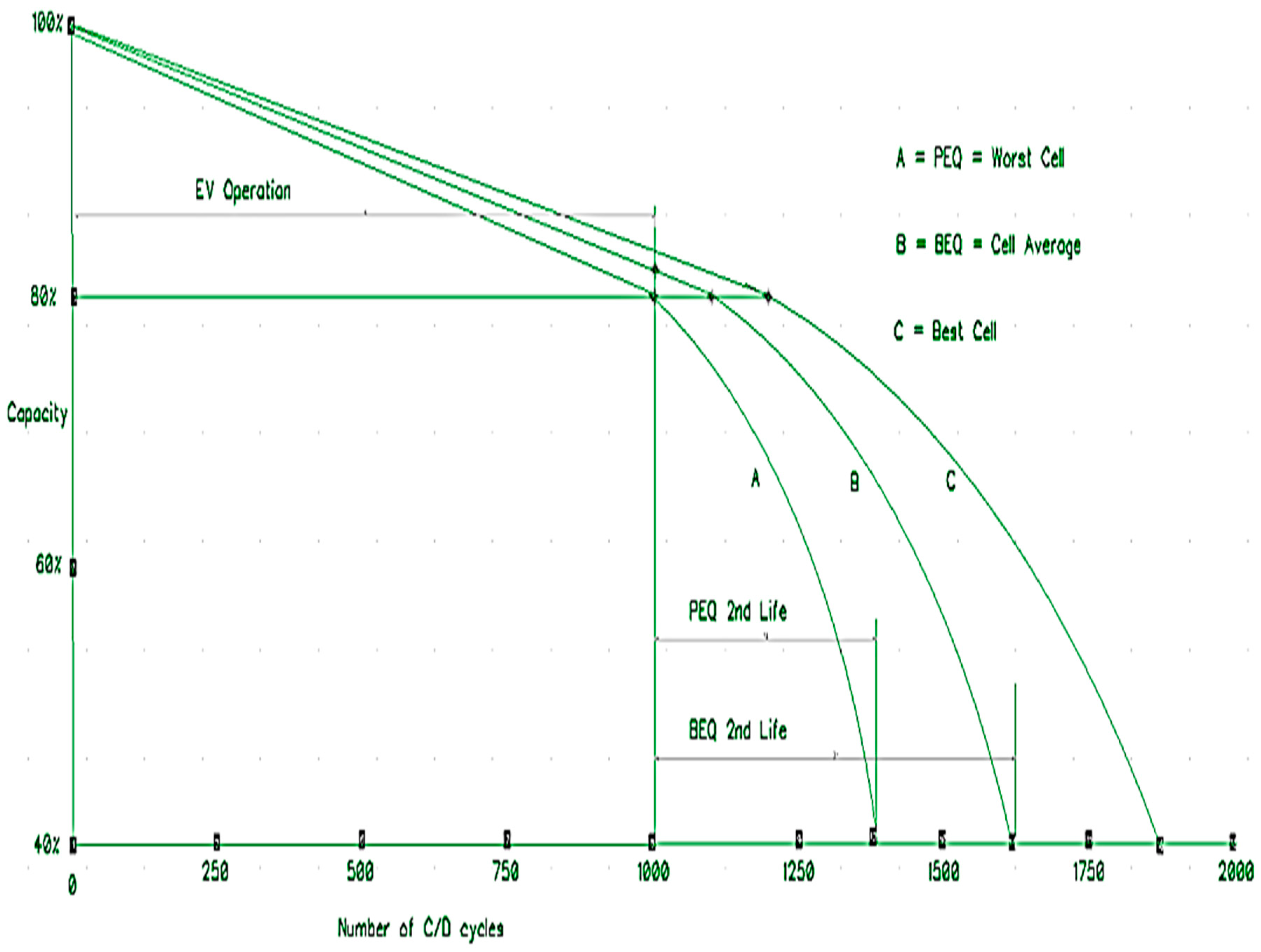
Figure 1 is an example graph showing the EV and second life (SL) regions of operation. Published plots of this type based on actual cell data are few since they are expensive and time consuming to produce, but one such example from [2] is reproduced here in Figure 2. Reference [3] shows a similar plot, although not based on data, and the study in [10] shows results based on data from an accelerated life test. It is well known that the capacity of a battery with a passive equalizer (PEQ) will be equal to that of the weakest cell, as indicated in Figure 1. It also will be shown later by analysis and experimental data that the bilevel equalizer (BEQ) described below can provide a battery capacity close to the average of the cells, as indicated in Figure 1. As seen from Figure 1, the EV and SL regions are very different, and this should be considered when designing the SL battery management system (BMS) and its cell voltage equalizer (EQU). As used here, the term “cell” refers either to a single large format cell or to a module consisting of several smaller cells connected in parallel.
First, it is useful to consider the requirements for an EQU in an SL application. As lithium-ion batteries age, two issues can cause their energy storage capacity to decrease:
- Differences in cell self-discharge (SD).
- Increased cell capacity fading (CF).
SD refers to cell leakage current, and it requires the use of an EQU over the entire life of the battery. Without an EQU operating at the cell level, differences in SD will cause the cell voltages to eventually diverge. This is because cells with higher SD will charge slower and discharge faster than those with lower SD. Since charging is limited by the maximum cell voltage and discharge is limited by the minimum, this divergence causes the effective battery capacity to decrease over time. Therefore, there must be some form of equalization at the cell level to mitigate this effect. Both passive equalizers (PEQs) that dissipate charge in higher voltage cells and active equalizers (AEQs) that transfer charge between the cells can do this, but PEQs are invariably used because of their much lower cost.
CF refers to the decrease in cell storage capacity that occurs with age and usage, as shown in Figure 1, which shows how each of the individual cell capacities decrease. Figure 1 also indicates the spread in cell capacities is usually not significant during EV operation, but it can become quite large during second life. Only an AEQ or an AEQ hybrid can mitigate CF, and only if it is operated while the battery is charging and discharging. In addition, the AEQ currents must be higher than those for a typical commercial PEQ or AEQ, and the AEQ must be bi-directional, i.e., it can add or remove charge from the cells. During discharge, the AEQ adds charge to the lower capacity cells to reduce their rate of discharge, and during charging it removes charge from these same cells to reduce their rate of charge. This increases the charge and discharge times and thus the capacity. It will be shown that if the above conditions are met, the bilevel EQU, an AEQ/PEQ hybrid, can provide a battery capacity close to the cell average.
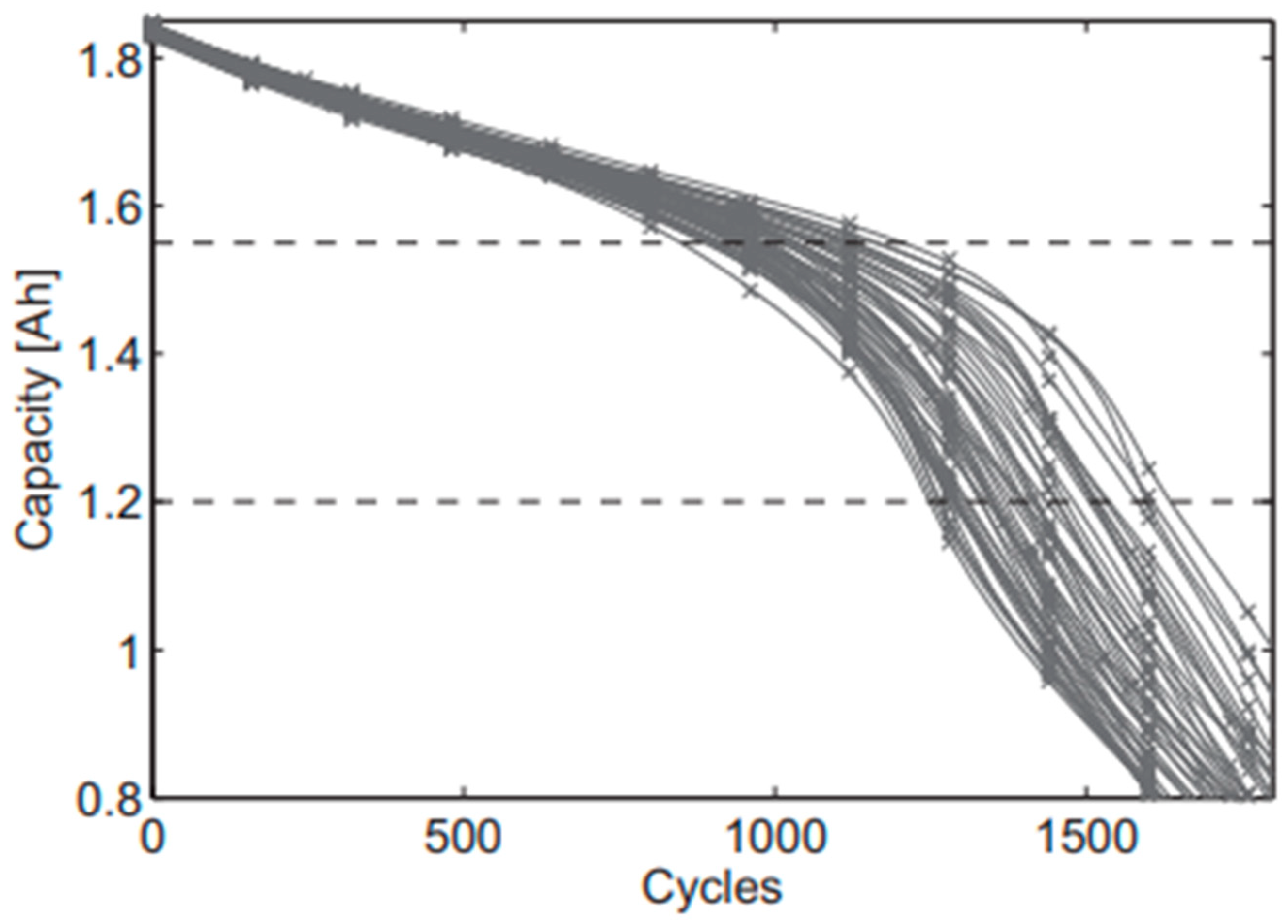
As indicated above, Figure 1 shows estimated plots for the minimum, average, and maximum cell capacity vs. number of charge/discharge (C/D) cycles for a typical lithium-ion battery during both EV and SL operation. The gradual CF in the EV region has been attributed to lithium loss, and the more rapid CF in the SL region to active material loss [1,2]. The EV and SL regions are sometimes referred to as the linear and nonlinear regions, respectively [3]. Figure 2 reproduced from [2] shows actual experimental plots for 48 nickel manganese cobalt (NMC) cells tested in a laboratory setting. These data show that the divergence in cell capacities becomes quite large in the nonlinear, i.e., SL, region. Additional analyses of cell capacity decrease caused by age and/or usage are provided in [10,11,12].
As shown from Figure 1 and Figure 2, PEQs which provide a battery capacity the same as the worst cell are adequate for EV operation since CF is not a major problem, and therefore the EQU only needs to compensate for SD. However, CF becomes dominant in the SL region, and there is a strong incentive to replace the original PEQ with an AEQ or AEQ hybrid that can shift operation from the worst cell plot, A, in Figure 1 to the cell average plot, B, in order to increase the battery lifetime. The problem, of course, is the much higher cost of AEQs such as those described in [13,14,15,16,17,18,19,20,21,22,23,24,25,26,27]. Because of this, most SL users appear to plan on using the original PEQs from the EV and accept the lower battery lifetime.
However, it will be shown below that the more recent bilevel EQU (BEQ) [28,29,30,31,32], an AEQ/PEQ hybrid, can provide an economical method to shift operation to the cell average plot, B, in Figure 1, and thus increase the battery lifetime, perhaps by about 50%. To maximize the economics, the BEQ would become a permanent part of the SL installation. Therefore, when an SL battery was replaced, the new battery would use the existing BEQ in the SL installation instead of its original PEQ from the EV.
2. Bilevel Equalizer Operation
As noted above, a battery with only a PEQ will follow the minimum plot, A, in Figure 1, i.e., the worst cell in the battery. However, it can be shown that a battery with a BEQ will follow close to the average plot, B, if the BEQ is operated while the battery is charging and discharging. To do this the BEQ uses the cell voltages to identify the cells that need to be serviced while the battery is active. Since these are not the open circuit voltages, this does not provide a precise value of the cell state of charge (SoC), but it does provide an adequate measure of the cell SoCs, relative to each other. This works well for cells such as nickel manganese cobalt (NMC) or nickel cobalt aluminum (NCA) whose voltage vs. SoC plots have a significant slope, but it is not effective for lithium iron phosphate (LFP) which has a very small slope over most of the SoC range. Of course, these batteries are expected to be reconditioned to replace their weaker cells before entering SL, but additional and significant capacity spread due to CF is still bound to develop during SL cycling and aging.
Assuming EV operation ends when the capacity has decreased to 80%, Figure 1 indicates a BEQ (plot B) would increase the total number of EV cycles by only a few percent above a PEQ (plot A). This is not cost effective and explains why virtually all EVs use less expensive PEQs, i.e., EV batteries only need to mitigate SD, not CF. However, for SL operation, the spread between plots A and B becomes much wider, indicating a large advantage for an AEQ or a BEQ.
The hypothetical example in Figure 1 assumes the EV battery reaches 80% capacity after 1000 charge/discharge (C/D) cycles. The battery is then removed from the EV, reconditioned, and begins its second life. If it uses a PEQ during its second life between the original 80% and 40% capacity values, it will continue to follow plot A until it reaches the original 1375 cycle value. This provides an SL lifetime of only 1375 − 1000 = 375 cycles. However, if the PEQ is replaced with a BEQ, second life follows plot B and ends at 1610 cycles. This provides a lifetime of 1610 − 1000 = 610 cycles, an increase of about 60% more than the PEQ. A similar analysis was done using the two horizontal dashed lines in Figure 2 from [2], one at 1.55 Ah (84%) and the other at 1.2 Ah (65%), i.e., SL would begin at 84% and end at 65%. A PEQ would follow the worst cell plot and provide an SL lifetime of 390 cycles. Assuming the average capacity is at the center of the 48 plots, a BEQ would provide a lifetime of 584 cycles which is an increase of almost 50% above the PEQ.
The BEQ is an AEQ/PEQ hybrid that operates at two different voltage levels, thus the term, bilevel. To implement a BEQ, the battery is divided into individual sections, each with a few series connected cells, as shown by the block diagram in Figure 3 for a battery with 4 sections. Typically, each section might consist of 4 to 10 cells, but larger numbers also can be used. Each section has a separate PEQ to balance its own cells, and the section voltages are balanced by AEQs. Thus, the PEQs compensate for SD at the cell level, and the AEQs compensate for CF at the section level.
Previous BEQ references, [28,29,30,31,32], described the basic BEQ functionality, but they did not explain how the role of the PEQs is to provide cell-level SD compensation for the cells within a section, and the role of the AEQs is to provide section-level CF compensation, i.e., two types of equalizers for two different problems. As will be explained later, this is done to minimize cost. Cell level PEQs are cheap and adequate for SD, but more expensive AEQs are required for CF. However, the AEQs in a BEQ are used at the section level instead of the cell level to reduce their number, and thus their cost. The earlier references cited above also did not have the benefit of a diagram similar to Figure 1 to show the lifetime advantage of a BEQ over a PEQ in the SL region.
A wide variety of AEQs have been proposed [13,14,15,16,17,18,19,20,21,22,23,24,25,26,27], virtually all of which operate at the cell level. Most of the drivers in these AEQs use some type of DC-DC converter with a transformer, but the AEQ used in the BEQ uses a simple inductive driver without a transformer. All of these previous references share a common problem in that they would be much more expensive to implement than the inductive driver used in the BEQ. This is especially true for the higher AEQ currents that are required for higher power designs and the larger imbalances in the cell capacity that occur in SL applications. Ref. [13] uses an isolated DC-DC converter with a transformer having multiple output windings to connect to the cells; however, it would seem this transformer could be complex and thus expensive for a large number of cells. The EQU in [14] is different from the others in that it uses a matrix of relays to switch selected cells to either a single DC-DC converter or a resistor. Although a technical success for its intended application, it proved to be a commercial failure because of cost. The studies in [15,20,22] are survey papers for a variety of EQUs, all operating at the cell level. References [16,17] are examples of integrated circuit controllers for AEQs, again operating at the cell level.
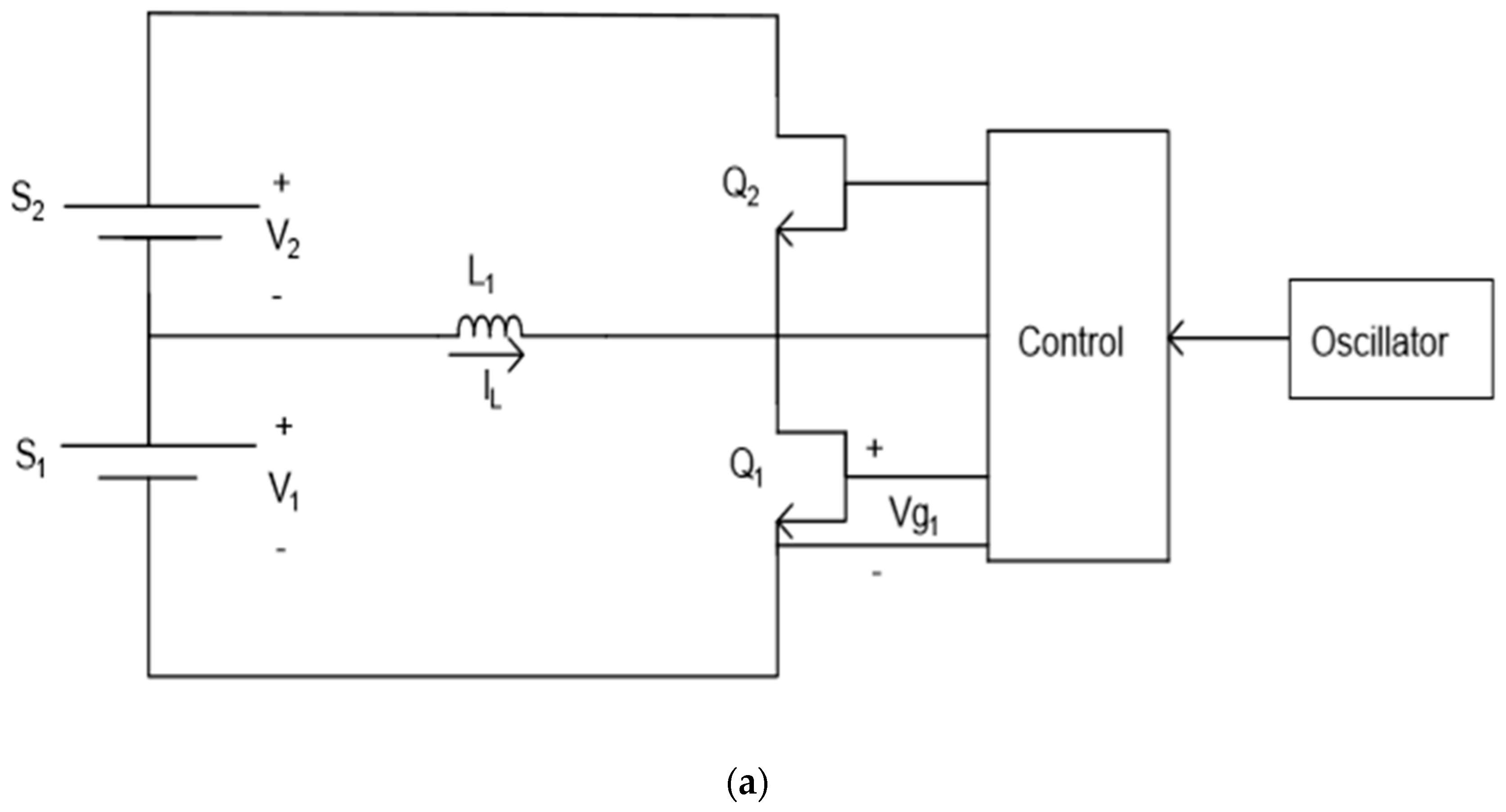
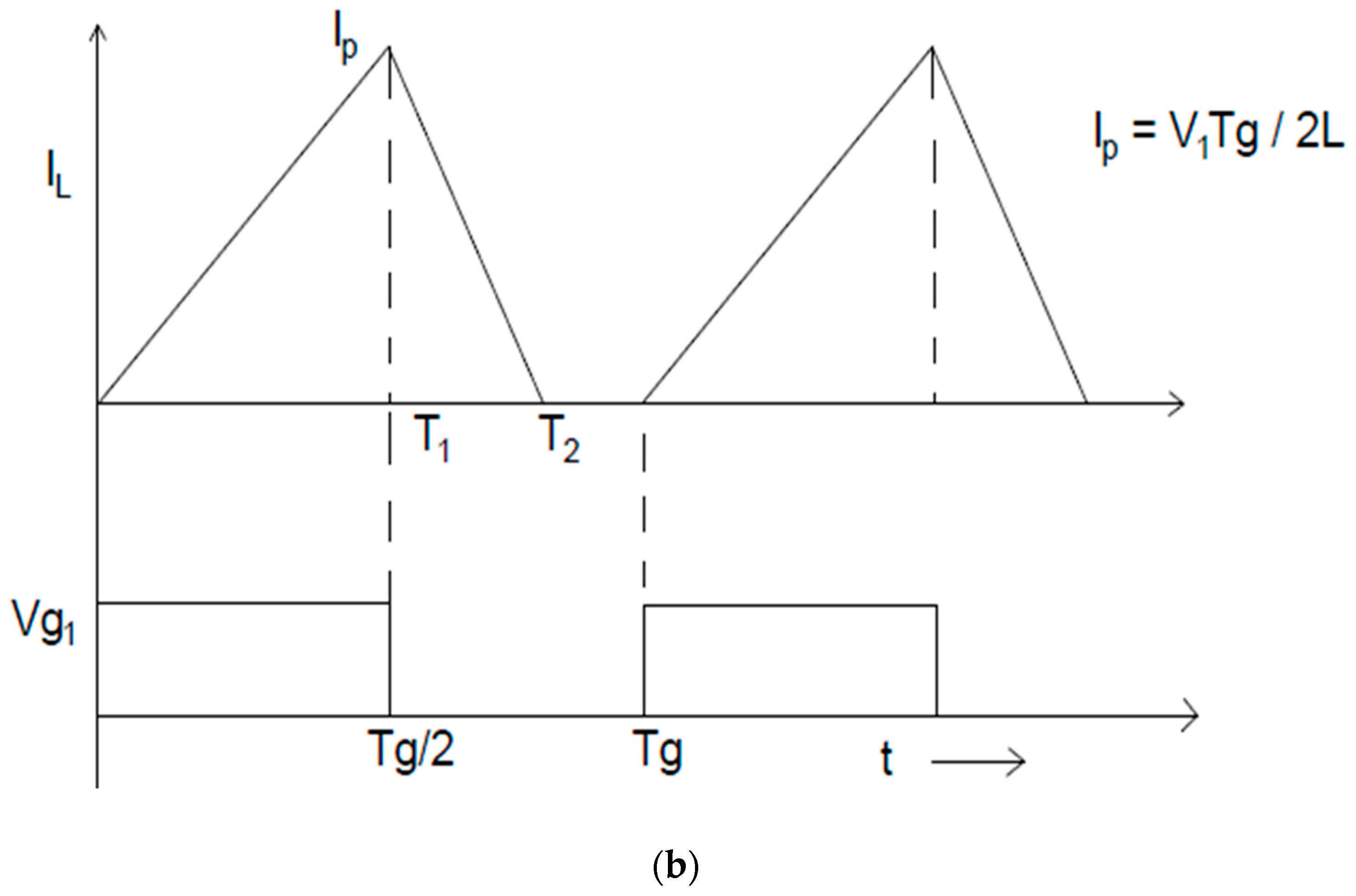
Figure 4a shows the schematic for one of the AEQ inductive drivers for the BEQ, and Figure 4b shows the IL current and Q1 gate drive voltage waveforms. More detailed descriptions of circuit operation are provided in [28,29,30,31,32], but the basic process to transfer energy from S1 to S4 is described in the following paragraph. The circuit in Figure 4a corresponds to each of the drivers, 1–3, in Figure 3.
For driver 1 in Figure 4a to transfer energy from section S1 to S2, the field effect transistor (FET), Q1, is switched on at the start of the first cycle in Figure 4b and turned off at time T1. Because of the energy stored in the inductor, L1, IL continues to flow and commutates to S2 via the parallel body diode in Q2. IL reaches zero at T2 once all the energy has been removed from L1. Because of losses, (T2 − T1) is always less than T1, so IL always reaches 0 before the start of the next cycle at Tg. If IL > 0 at Tg, IL for the next cycle would have a higher peak value, Ip, and the current would become excessive on subsequent cycles, i.e., the circuit would fail. Drivers 2 and 3 operate in a similar manner to transfer energy from S2 to S4 in Figure 3.
The main reason cell-level AEQs are so much more expensive than PEQs is the cost of the AEQ drivers, and the reason the BEQ is so much cheaper than cell-level AEQs is that it uses very simple section-level AEQ drivers and fewer of them. For example, a 192-cell battery might consist of 48 sections of 4 cells each. Therefore, a cell-level inductive AEQ would require 191 drivers (number of cells—1), but the AEQ in a BEQ with 4 cells/section would only require 47 drivers. If the BEQ used 8 cells/section, it would only require 23 drivers. Of course, a driver for eight cells will cost more than one for four because L1 will be larger and Q1 and Q2 will require a higher voltage rating. However, analysis shows that the additional cost is much less than 2×, so the BEQ with eight cells/section would have a lower total cost. There is a cost/performance tradeoff however since each section uses a PEQ at the cell level, and this means the section capacity is equal to that of its weakest cell. Therefore, the BEQ with four cells/section will probably provide a higher battery capacity than the one with eight.
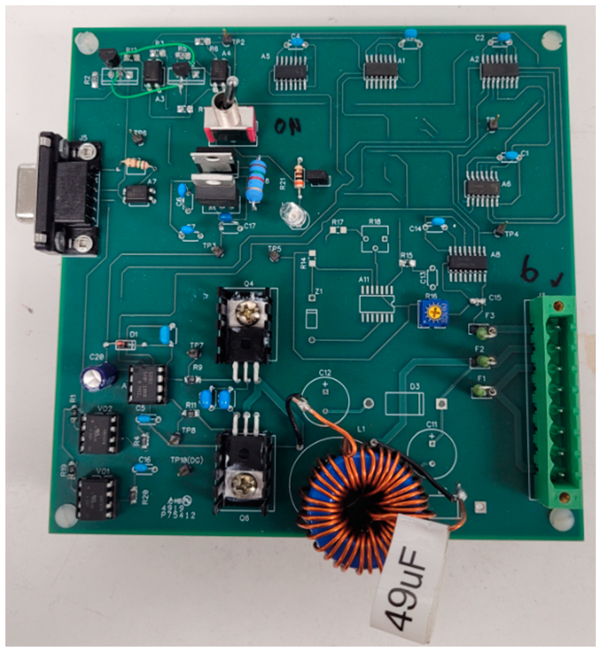
Figure 5 shows the circuit board for one of the inductive AEQ drivers in a BEQ with four cells/section. The toroid at the bottom edge of the board is the inductor, L1, in Figure 4a. The two FETs mounted on small heatsinks to the left of the toroid are Q1 and Q2 in Figure 4a. Q1 and Q2 should be mounted close together to minimize the parasitic series inductance between them. This is necessary to reduce the voltage transients that occur across the FETs when they are switched. This particular board did not include one of the optional features, so some of the footprints for certain parts are vacant.
If the necessary electrical connection points are available, the BEQ can be implemented by adding an AEQ retro kit to the existing PEQ and changing the system software. When the battery reaches the end of its second life, the same BEQ can continue to be used with a replacement battery. The BEQ hardware would be the same for any battery of the same capacity and number of cells, and it could be reprogrammed to accommodate different manufacturers. Of course, some standardization of battery packs would enhance the ability to accommodate batteries from various EVs.
3. Battery Capacity with a BEQ
As noted above, a PEQ only provides a battery capacity equal to that of the weakest cell in the entire battery. However, a battery with a BEQ is divided into sections, so a weak cell only affects the capacity of its own section, and the section capacity is the same as its weakest cell. The AEQ within the BEQ then operates at the section level to provide a battery capacity almost equal to the average of the sections. This is illustrated by the following examples.
- A.
- Example 1
This example is for a discharge cycle for a battery with 4 sections, as shown in Figure 3, and the analysis is the same for any number of cells per section. As noted above, the capacity of each section is determined by its weakest cell since PEQs are used at the cell level within the section, and this cell will have the lowest voltage in the section during discharge.
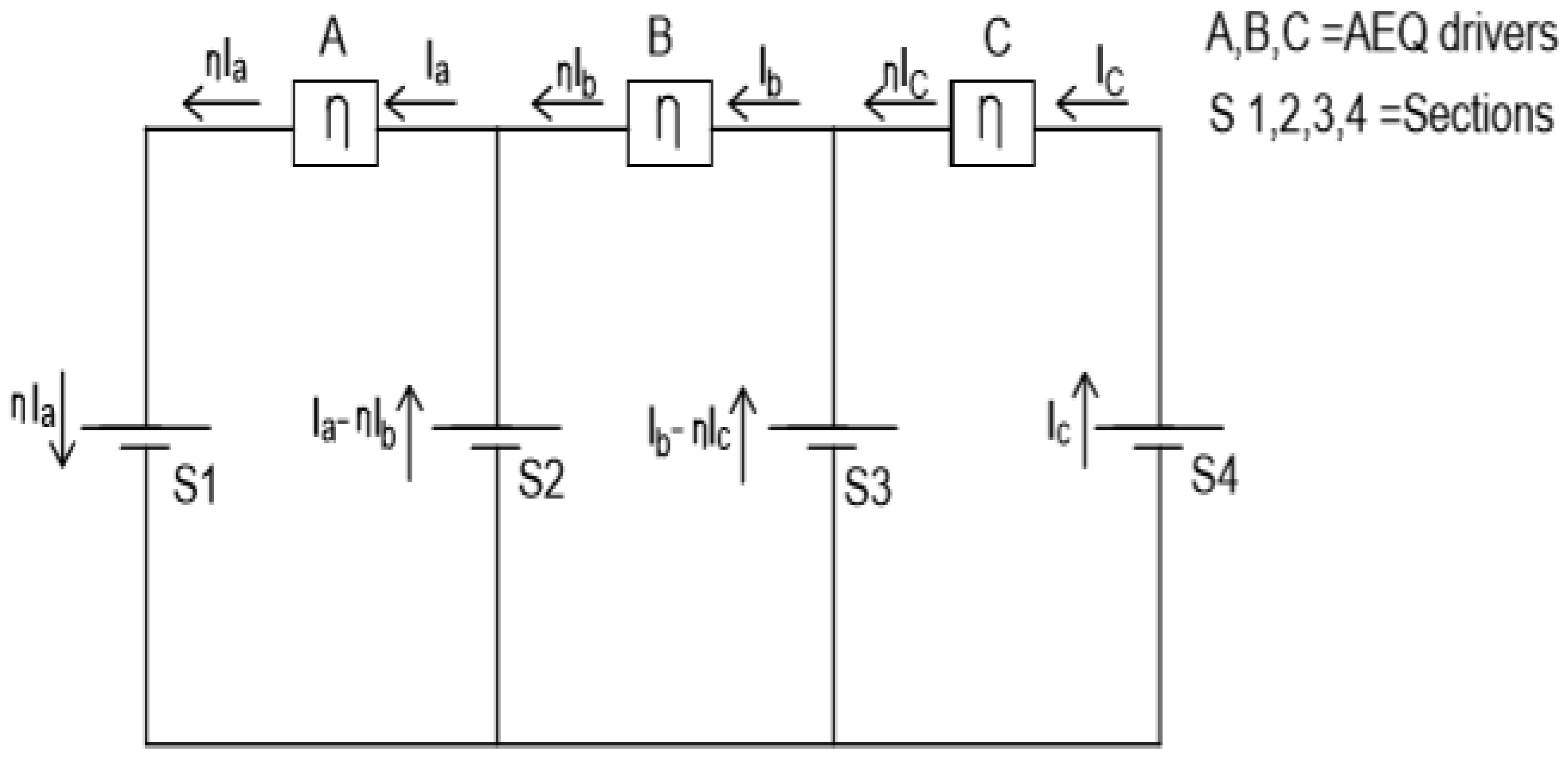
The four sections, S1–S4, have the following capacities: AH1 = 30 Ah, AH2 = AH3 = 45 Ah and AH4 = 60 Ah. Three AEQ drivers, A, B and C, like those in Figure 4a are required, and in this case, they will transfer charge from S2, S3 and S4 into S1. Since the PEQs only operate at the cell level they do not affect the AEQ analysis at the section level.
Figure 6 is an equivalent circuit showing the equalization (or driver) currents, Ia, Ib and Ic, between the sections, S1–S4, and the AEQ drivers, A to C. Because of losses, the current exiting each driver is reduced by an efficiency factor, η, e.g., the average current into A = Ia and the average current out of A = η × Ia. This can be seen from the inductor current waveforms in Figure 4b. The difference between the section voltages, such as V1 and V2 in Figure 4a is small, so η is also essentially the same as the AEQ circuit efficiency. For example, the average value of the triangular current before T1 in Figure 4b would be Ia, and the average value of the part from T1 to T2 would be η × Ia.
Assume the following specifications:
- ID = discharge current = 10 Adc.
- T = discharge time.
- η = AEQ efficiency = 0.9.
Maximum discharge capacity will be achieved if all sections reach full discharge at the same time, and the AEQ ensures this by equalizing the section voltages over the complete discharge cycle. Therefore,
(ID − η × Ia)T = AH1
(ID + Ia − η × Ib)T = AH2
(ID + Ib − η × Ic)T = AH3
(ID + Ic)T = AH4
Defining P = 1/T,
Solving (5) for Ia, Ib, Ic, and P,
Ia = 3.5 Adc, Ib = 3.59 Adc, Ic = 3.69 Adc, 1/P = T = 4.382 h
The battery capacity = ID × T = 43.82 Ah, as compared to 30 Ah (same as AH1) when only a PEQ is used, an increase of 46%. Note that the average capacity of the four sections is 45 Ah so the BEQ provides a capacity within 2.26% of the average of the sections.
These calculated currents are the average values, but the actual AEQ currents do not flow continuously since they switch on and off as the cell voltages vary during discharge. Therefore, the AEQ circuit should be designed so that its maximum available current is somewhat higher than the required average. For example, instead of designing to produce a max current of 3.69 Adc, each AEQ driver should be designed to provide a somewhat higher current, perhaps 4 Adc. This allows the driver to produce the required average current as it switches on and off during discharge. If there were four cells/section, this value of 4 Adc would be economical for a BEQ with three AEQ drivers operating at the section level, but it would be very expensive for a cell-level AEQ with 15 drivers. If there were 10 cells/section, there would still be 3 drivers for the BEQ but 39 for a cell-level AEQ.
Another issue is the variation of the driver currents if they are unregulated. If the cell voltage range is 4.2 Vdc at full charge and 2.8 Vdc at full discharge, this means the driver currents would have decreased by about 33% by the end of discharge. Fortunately, it is quite simple to design the AEQ controller so that the period, Tg, in Figure 4b is inversely proportional to the battery voltage. As shown by the equation in Figure 4b, this will keep the peak and thus the average driver currents virtually constant over the entire voltage range.
- B.
- Example 2
As expected, the required Ia, Ib and Ic will increase for higher values of ID. If ID from Example 1 is increased to 20 Adc for another battery with the same AH rating at this higher value of ID, (5) yields the following results,
Ia = 7.01 Adc, Ib = 7.19 Adc, Ic = 7.39 Adc, and T = 2.191 h
The capacity is still 43.82 Ah, but the required AEQ currents have doubled along with ID. These currents are still technically feasible but obviously would be more expensive to implement.
If the current limit of 4 Adc from Example 1 was used, the AEQ would still operate properly, but the capacity increase would be less. With a limit of 4 Adc for all the AEQ currents, S1 would reach full discharge first, so from (1),
(20 − 0.9 × 4)T = 30 and T = 1.829 h
Therefore, the actual capacity would be 20 × 1.829 = 36.58 Ah which is lower than the 43.82 Ah maximum, but still 22% higher than the 30 Ah provided by a PEQ.
4. Experimental Results
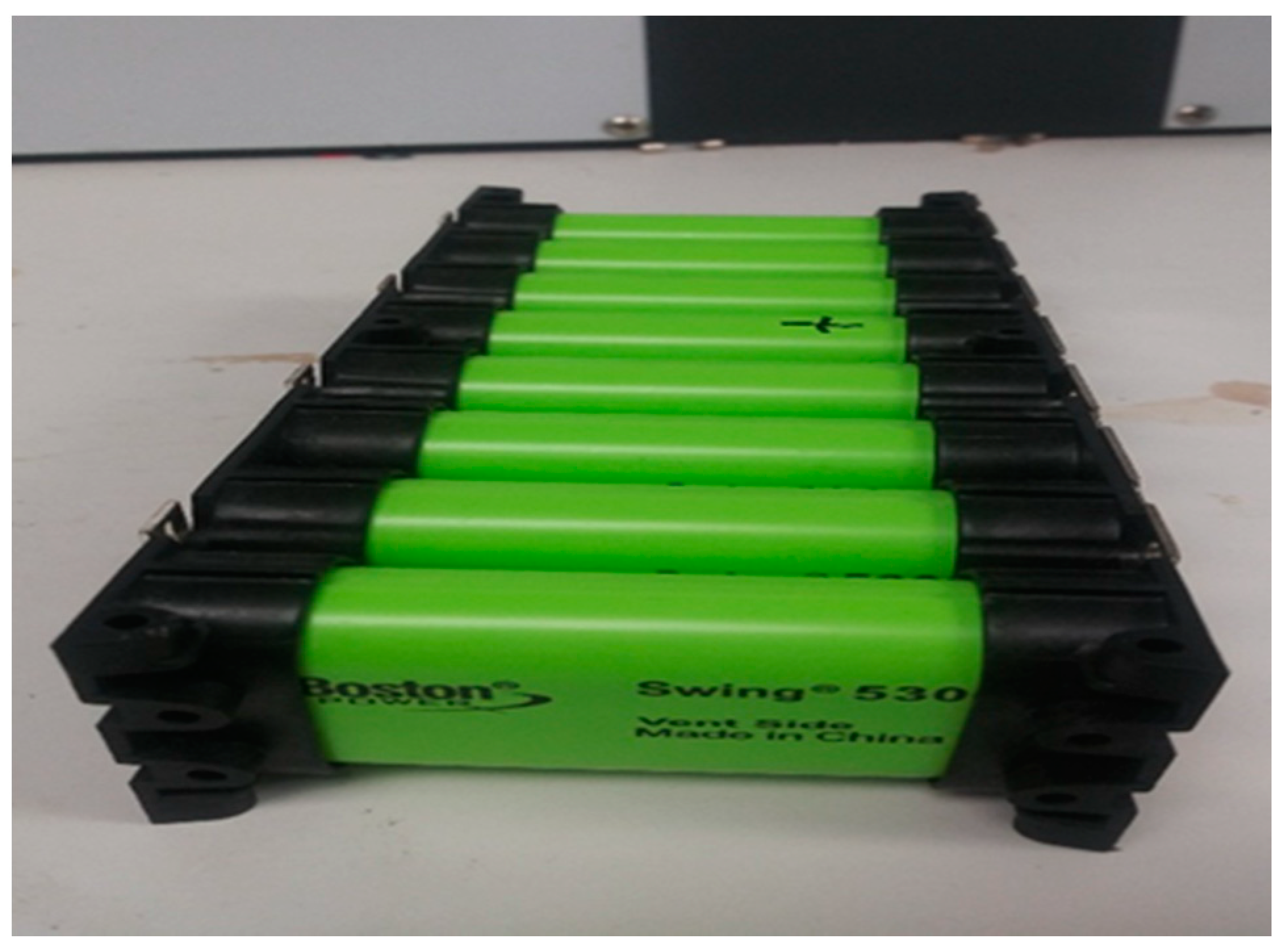
A BEQ lab prototype was developed and tested with a cobalt oxide Li-ion battery with 24S-8P cells, i.e., there were 24S modules, each with 8P cells. Each “cell” of this battery is actually a module consisting of eight Boston Power Swing 5300 cobalt oxide cells connected in parallel. Each of these cells will now be referred to as blocks, and each has a manufacturer’s C/5 rated capacity of 5 Ah each. These blocks were about 3 or 4 years old and had experienced numerous charge/discharge cycles. A typical cell with 8P blocks is shown in Figure 7.
Since each block had a C/5 rating of 5 Ah, a cell with 8P blocks would have a C/5 rating of 40 Ah. This corresponds to a C/5 discharge current of 8 Adc, but these experiments used a resistive load that provided an average current of 12 Adc. Because of the higher discharge current and cell aging, it was estimated that the actual discharge capacity of each block was only about 4 Ah, or a cell capacity of 32 Ah.
Estimated Discharge Capacity of each 8P cell module: 32 Ah (2.8 Vdc < Vcell < 4.0 Vdc).
Average discharge current: ID = 12 Adc.
Number of sections: 6.
Number of series connected cell modules/section: 4.
The BEQ specifications:
Number of AEQ drivers: 5.
AEQ equalization current: 3 Adc (this is the current flowing out of a section).
AEQ efficiency at a section voltage of 14 Vdc: 75%.
Nominal AEQ frequency: 16 kHz (varies with section voltage to regulate equalization current).
- A.
- Test #1
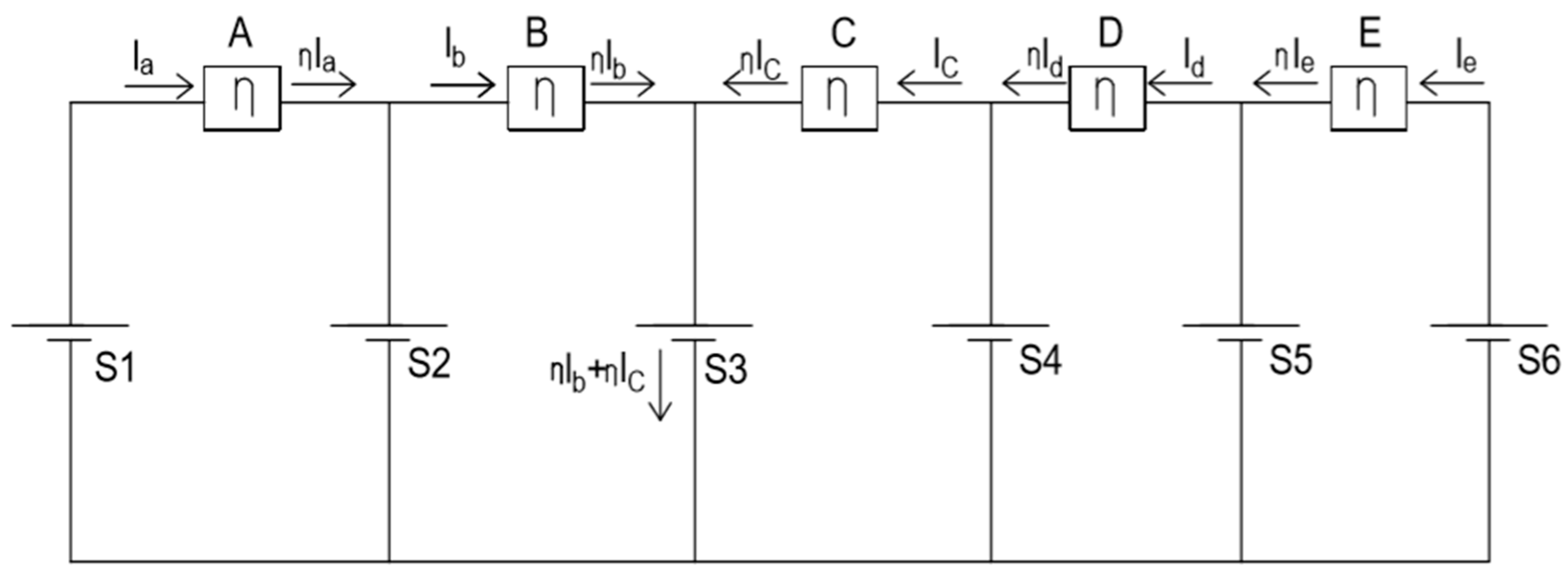
To compare the calculations with the experimental results, a test was performed with a 25% imbalance by removing 2 of the 8P cells from module #9 in section S3. Therefore, the capacity of S3 = 24 Ah, while all other sections remain at 32 Ah. Figure 8 shows the equivalent circuit during discharge for this case. From Figure 8, using the variables similar to those in Equations (1)–(5):
(ID + Ia)T = AH1
(ID − ηIa + Ib)T = AH2
(ID − ηIb − ηIc) = AH3
(ID + Ic − ηId)T = AH4
(ID + Id − ηIe)T = AH5
(ID + Ie)T = AH6
Defining P = 1/T, AH = AH1, 2, 4, 5 and 6, and U = unitary vector:
Solving (12), Ia = 0.67 Adc, Ib = 1.34 Adc, Ic = 1.55 Adc, Id = 1.17, Ie = 0.67, and T = 2.53 h. The capacity is 30.36 Ah as compared to 24 Ah when only a PEQ is used, an increase of 26.5%. Note that the average capacity of the six sections is 30.67 Ah so the BEQ provides a battery capacity very close to the average of the sections. Calculated and measured results are summarized in Table 1, where Ieq = equalization current.
A full discharge test at an average ID = 12 Adc was first performed on the battery with the BEQ replaced by a conventional PEQ. This was done simply by changing the software and using only the PEQs. The measured PEQ discharge capacity was 23.0 Ah, as compared to the 24 Ah value used in the calculations.
The PEQ was then replaced by the BEQ, and the battery was given a full charge and then discharged at the same ID = 12 Adc. The measured discharge capacity was 27.2 Ah, an increase of 18.3% above the PEQ test and 89.7% of the calculated value. Recall that for the calculations, the 40 Ah rating was reduced to an estimate of 32 Ah due to aging and the 12 Adc discharge current instead of the C/5 value of 8 Adc. Apparently the 32 Ah estimate was still slightly too high.
The calculations indicate an average AEQ current of 1.55 Adc is needed, so the actual maximum DC value of 3 Adc should be adequate to produce a 1.55 Adc average over the cycle (recall that the AEQ currents modulate on and off during the discharge period). The results are summarized in Table 1.
- B.
- Test #2
Now consider a more extreme case with a 50% reduction in S3, i.e., AH3 = 16 Ah.
Solving (12), Ia = 1.42 Adc, Ib = 2.83 Adc, Ic = 3.28 Adc, Id = 2.48 Adc, Ie = 1.42 Adc, T = 2.39 h, and the capacity is 28.68 Ah. This indicates the maximum AEQ current of 3 Adc will not be adequate to provide full capacity equalization. Calculated and measured results are again shown in Table 1.
As before, a full discharge test at an average ID = 12 Adc was first performed on the battery with the BEQ replaced by a conventional PEQ. The measured discharge capacity in this case was 15.07 Ah, which was reasonably close to the predicted 16 Ah.
Next, a full discharge at ID = 12 Adc was done using the BEQ, but the discharge capacity was only 21.2 Ah. This is considerably less that the calculated maximum of 28.68 Ah which required an average AEQ current of 3.28 Adc. Although the maximum Ieq of 3 Adc is close to 3.28 Adc, it is still too low to achieve the calculated capacity. However, it still provides 40.7% more capacity than it does with the conventional PEQ. Recall that to obtain an average of 3.28 A the maximum Ieq must be significantly higher since the Ieq currents do not flow continuously during the discharge period. To achieve the calculated value of 28.68 Ah would probably require an Ieq of 4 or 5 Adc. These results are also shown in Table 1.
5. Conclusions and Future Development
The BEQ is a hybrid that uses a PEQ to compensate for differences in SD at the cell level and an AEQ to mitigate CF at the section level. This approach is used to reduce the number of AEQ drivers and thus cost. The AEQ in the BEQ also uses a simple inductive driver, and this too helps to reduce cost. Staged cell imbalance test results are shown for a 24-cell battery, and these show reasonable agreement between the calculated and experimental results.
However, most of the proposed second life applications for used EV batteries appear to plan on retaining the original PEQs from the EV. As with the EV, this limits the battery capacity to that of the worst cell, whereas a BEQ could provide a capacity close to the cell average which is much higher. Analysis shows that the difference in lifetime between the worst cell and the cell average can become quite large in the SL region, and this means a BEQ will provide a much higher number of cycles than a PEQ before the battery reaches the end of its second life. Figure 1 shows hypothetical plots used to illustrate this difference, and an analysis based on actual data from Figure 2 from [2] shows that this increase could be in the range of about 50%. It would seem that this could greatly benefit the economics of second life applications. The data in [2] were obtained under uniform temperature for each of the cells, but it is well known that temperature variations within a battery lead to even wider differences in cell capacity. This indicates the actual differences in cell capacity for SL installations may be even greater than those in [2].
One problem is that published data similar to that in [2] seem to be very limited. Reference [10] seems to agree with this, and in fact, a copy of the data plots from [2] is also included in [10]. Data of this type are very important in estimating SL lifetime, but obtaining them is both expensive and time consuming. This indicates the need for faster and cheaper ways to perform these measurements. This is especially important in light of the rapid changes in EV battery technology. New developments include new anodes using lithium metal instead of carbon to increase energy density, and new lower cobalt cathodes to reduce cost [33,34].
Since the BEQ hardware is basically an AEQ overlay on a conventional PEQ, it should be possible to implement this with a retro kit along with new software. However, this still might be difficult to implement unless the EV manufacturer makes provisions for this in the original BMS design. Fortunately, several manufacturers have shown an interest in the second life market since it provides an additional source of revenue, and some are planning to use BMS designs that accommodate SL applications [9]. Perhaps some of these will eventually include provisions for improved SL equalizers.
Author Contributions
N.S.M. and T.S. conceived and designed the experiments; N.S.M., B.S. and T.S. performed the experiments; T.S. analyzed the data; N.S.M., B.S. and T.S. designed and built the test equipment and analysis tools; N.S.M., B.S. and T.S. wrote the paper. All authors have read and agreed to the published version of the manuscript.
Funding
This work was supported in part by the University of Toledo Rocket Fuel Fund #R-1258/17-02-W16.
Institutional Review Board Statement
Not applicable.
Informed Consent Statement
Not applicable.
Data Availability Statement
Data is contained within the article.
Conflicts of Interest
The authors declare no conflict of interest. The funders had no role in the design of the study; in the collection, analyses, or interpretation of data; in the writing of the manuscript, or in the decision to publish the results.
Glossary
| Adc | DC Amps |
| Ah | Amp Hours |
| BEQ | Bilevel Equalizer |
| EQU | Equalizer |
| FET | Field Effect Transistor |
| hrs | Hours |
| I | Current |
| PEQ | Passive Equalizer |
| AEQ | Active Equalizer |
| T | Time |
| Vdc | DC Voltage |
References
- Dubarry, M.; Truchot, C.; Liaw, B.; Gering, K.; Sazhin, S.; Jamison, D.; Michelbacher, C. Evaluation of commercial lithium-ion cells base on composite positive electrode for plug-in hybrid applications. Part II. Degradation mechanism under 2C cycle aging. J. Power Sources 2011, 196, 10336–10343. [Google Scholar]
- Baumhofer, T.; Bruhl, M.; Rothgang, S.; Sauer, D. Production caused variation in capacity aging trend and correlation to initial cell performance. J. Power Sources 2014, 247, 332–338. [Google Scholar] [CrossRef]
- Rohr, S.; Muller, S.; Baumann, M.; Kerler, M.; Ebert, F.; Kaden, D.; Lienkamp, M. Quantifying uncertainties in reusing lithium-ion batteries from electric vehicles. Procedia Manuf. 2017, 8, 603–610. [Google Scholar] [CrossRef]
- Second-Life Electric Vehicle Batteries 2019–2029. Available online: http://www.idtechex.com/research/reports/second-life-electric-vehicle-batteries-2019-2029-000626.asp (accessed on 3 March 2019).
- Li, H.; Alsolami, M.; Yang, S.; Alsmadi, Y.M.; Wang, J. Lifetime test design for second-use electric vehicles batteries in residential applications. IEEE Trans. Sustain. Energy 2017, 8, 1736–1746. [Google Scholar] [CrossRef]
- Gohla-Neudecker, B.; Bowler, M.; Mohr, S. Battery 2nd life: Leveraging the sustainability potential of EVs and renewable energy grid integration. In Proceedings of the 2015 International Conference on Clean Electrical Power (ICCEP), Taormina, Italy, 16–18 June 2015; pp. 311–318. [Google Scholar]
- Abdel-Monem, M.; Hegazy, O.; Omar, N.; Trad, K.; van den Bossche, P.; van Mierlo, J. Lithium-Ion batteries: Comprehensive technical analysis of second-life batteries for smart grid applications. In Proceedings of the 2017 19th European Conference on Power Electronics and Applications (EPE’17 ECCE Europe), Warsaw, Poland, 11–14 September 2017. [Google Scholar]
- Mathews, I.; Xu, B.; He, W.; Barreto, V.; Buonassi, T.; Peters, I. Technoeconomic model of second-life batteries for utility-scale solar considering calendar and cycle aging. Appl. Energy 2020, 269. [Google Scholar] [CrossRef]
- Second Life: Carmakers and Storage Startups Get Serious About Reusing Batteries. Available online: https://www.greentechmedia.com/articles/read/car-makers-and-startups-get-serious-about-reusing-batteries (accessed on 15 November 2020).
- Harris, S.J.; Harris, D.J.; Li, C. Failure statistics for commercial Lithium Ion batteries: A study of 24 pouch cells. J. Power Sources 2017, 342, 589–597. [Google Scholar] [CrossRef] [Green Version]
- Paul, S.; Diegelmann, C.; Kabza, H.; Tillmetz, W. Analysis of ageing inhomogeneities in Lithium-Ion battery systems. J. Power Sources 2013, 239, 642–650. [Google Scholar] [CrossRef]
- Schuster, M.J.; Brand, M.J.; Berg, P.; Gleissenberger, M.; Jossen, A. Lithium-Ion cell-to-cell variation during battery electric vehicle operation. J. Power Sources 2015, 297, 242–251. [Google Scholar] [CrossRef]
- Kutkut, N.; Wiegman, H.; Divan, D.; Novotny, D. Design considerations for charge equalization of an electric vehicle battery system. IEEE Trans. Ind. Appl. 1999, 35, 96–103. [Google Scholar] [CrossRef] [Green Version]
- Stuart, T.A.; Zhu, W. Fast equalization for large Lithium Ion batteries. IEEE Aerosp. Electron. Syst. Mag. 2009, 24, 27–31. [Google Scholar] [CrossRef] [Green Version]
- Gallardo-Lozano, J.; Romero-Cadaval, E.; Milanes-Montero, M.; Guerrero-Martinez, M. Battery equalization active methods. J. Power Sources 2014, 246, 934–949. [Google Scholar] [CrossRef]
- Analog Devices. LTC3300-1 High Efficiency Bidirectional Multicell Battery Balancer; Linear Technology Datasheet LT1213 REV B; Analog Devices: Norwood, MA, USA, 2013. [Google Scholar]
- Texas Instruments Incorporated. EM1401EVM User’s Guide; Texas Instruments Publication SNOU128; Texas Instruments Incorporated: Dallas, TX, USA, 2014. [Google Scholar]
- Zhang, D.-A.; Zhu, G.-R.; He, S.-J.; Qiu, S.; Ma, Y.; Wu, Q.-M.; Chen, W. Balancing control strategy for li-ion batteries string based on dynamic balanced point. Energies 2015, 8, 1830–1847. [Google Scholar] [CrossRef] [Green Version]
- Lee, K.M.; Lee, S.W.; Choi, Y.G.; Kang, B. Active balancing of Li-Ion battery cells using transformer as energy carrier. IEEE Trans. Ind. Electron. 2017, 64, 1251–1257. [Google Scholar] [CrossRef]
- Han, W.; Zhang, L.; Han, Y. Mathematical modeling, performance analysis and control of battery equalization systems: Review and recent developments. In Advances in Battery Manufacturing, Service, and Management Systems, 1st ed.; John Wiley & Sons, Inc.: New York, NY, USA, 2017; pp. 281–298. [Google Scholar]
- Han, W.; Zou, C.; Zhou, C.; Zhang, L. Estimation of cell SOC evolution and system performance in module-based battery charge equalization systems. IEEE Trans. Smart Grid 2018, 10, 4717–4728. [Google Scholar] [CrossRef]
- Hu, X.; Zou, C.; Zhang, C.; Li, Y. Technological developments in batteries: A survey of principal roles, types, and management needs. IEEE Power Energy Mag. 2017, 15, 20–31. [Google Scholar] [CrossRef]
- Ouyang, Q.; Chen, J.; Zheng, J.; Fang, H. Optimal cell-to-cell balancing topology design for serially connected Lithium-Ion battery packs. IEEE Trans. Sustain. Energy 2018, 9, 350–360. [Google Scholar] [CrossRef]
- Lim, C.-S.; Lee, K.-J.; Ku, N.-J.; Hyun, D.-S.; Kim, R.-Y. A modularized equalization method based on magnetizing energy for a series connected Lithium-Ion battery string. IEEE Trans. Power Electron. 2014, 29, 1791–1799. [Google Scholar] [CrossRef]
- Park, H.S.; Kim, C.H.; Park, K.B.; Moon, G.W.; Lee, J.H. Design of a charge equalizer based on battery modularization. IEEE Trans. Veh. Technol. 2009, 58, 3216–3223. [Google Scholar] [CrossRef]
- Kim, C.H.; Kim, M.Y.; Park, H.S.; Moon, G.W. A modularized two-stage charge equalizer with cell selection switches for series connected Lithium-Ion battery string in an HEV. IEEE Trans. Power Electron. 2012, 27, 3764–3774. [Google Scholar] [CrossRef]
- Lin, X.; Stefanopoulou, A.G.; Li, Y.; Anderson, R.D. State of charge imbalance estimation for battery strings under reduced voltage sensing. IEEE Trans. Control Syst. Technol. 2015, 23, 1052–1062. [Google Scholar]
- Stuart, T.A. Bilevel Equalizer for Battery Cell Charge Management. U.S. Patent 10,862,318 B2, 8 December 2020. [Google Scholar]
- Mubenga, N.; Linkous, Z.; Stuart, T. A bilevel equalizer for large lithium ion batteries. Batteries 2017, 3, 39. [Google Scholar] [CrossRef] [Green Version]
- Mubenga, N. A Lithium-Ion Battery Management System with Bilevel Equalization. Ph.D. Thesis, University of Toledo, Toledo, OH, USA, 2017. Available online: https://etd.ohiolink.edu/ (accessed on 5 December 2017).
- Mubenga, N.; Linkous, Z.; Stuart, T. A bilevel equalizer for lithium ion batteries. In Proceedings of the IEEE National Aerospace & Electronics Conference 2018, Dayton, OH, USA, 23–26 July 2018. [Google Scholar]
- Mubenga, N.; Sharma, K.; Stuart, T. A bilevel equalizer to boost the capacity of second-life batteries. Batteries 2019, 5, 55. [Google Scholar] [CrossRef] [Green Version]
- GM Develops Lower Cost Ultium Lithium-Ion Batteries To Power New Electric Vehicle Line. Available online: https://www.forbes.com/sites/samabuelsamid/2020/03/04/gm-announces-new-lower-cost-ultium-lithium-ion-batteries-for-new-evs/?sh=2d8148e44f10 (accessed on 3 November 2020).
- Available online: https://www.sae.org/news/2020/05/gm-ultium-battery-update (accessed on 10 November 2020).
Figure 1.
Capacity vs. number of charge/discharge cycles for electric vehicle (EV) and second life (SL) operation.
Figure 1.
Capacity vs. number of charge/discharge cycles for electric vehicle (EV) and second life (SL) operation.

Figure 2.
Capacity vs. number of charge/discharge cycles for 48 nickel manganese cobalt (NMC) cells. Cells from [2]. Reproduced with permission from [2].

Figure 3.
Bilevel equalizer (BEQ) connections for a battery with 4 sections.

Figure 4.
Basic inductive active equalizer (AEQ) driver and waveforms. (a) Inductive AEQ driver connected to battery sections S1 and S2. (b) Inductor current, IL, and Q1 gate drive waveforms.
Figure 4.
Basic inductive active equalizer (AEQ) driver and waveforms. (a) Inductive AEQ driver connected to battery sections S1 and S2. (b) Inductor current, IL, and Q1 gate drive waveforms.


Figure 5.
Inductive driver board prototype for a BEQ with 4 cells/section.

Figure 6.
Equivalent AEQ circuit in the BEQ.

Figure 7.
Cell module with 8 Boston Power Swing 5300 blocks.

Figure 8.
Equivalent AEQ circuit for Tests 1 and 2.


Table 1.
Calculated and measured results for Test #1 and Test #2.
| Test Case | Calculated | Measured | |||||
|---|---|---|---|---|---|---|---|
| Test | AH | Ieq | AH | AH Gain | Ieq | AH | AH Gain |
| #1 no BEQ | 75% | n/a | 24 | n/a | n/a | 23 | n/a |
| #1 BEQ | 75% | 1.55A | 30.31 | 26.3% | 3A | 27.2 | 18.3% |
| # 2 no BEQ | 50% | n/a | 16 | n/a | n/a | 15.07 | n/a |
| #2 BEQ | 50% | 2.42A | 28.68 | 79.3% | 3A | 21.2 | 40.7% |
Publisher’s Note: MDPI stays neutral with regard to jurisdictional claims in published maps and institutional affiliations. |
© 2021 by the authors. Licensee MDPI, Basel, Switzerland. This article is an open access article distributed under the terms and conditions of the Creative Commons Attribution (CC BY) license (http://creativecommons.org/licenses/by/4.0/).
Share and Cite
MDPI and ACS Style
Mubenga, N.S.; Salami, B.; Stuart, T. Bilevel vs. Passive Equalizers for Second Life EV Batteries. Electricity 2021, 2, 63-76. https://0-doi-org.brum.beds.ac.uk/10.3390/electricity2010004
AMA Style
Mubenga NS, Salami B, Stuart T. Bilevel vs. Passive Equalizers for Second Life EV Batteries. Electricity. 2021; 2(1):63-76. https://0-doi-org.brum.beds.ac.uk/10.3390/electricity2010004
Chicago/Turabian StyleMubenga, Ngalula Sandrine, Boluwatito Salami, and Thomas Stuart. 2021. "Bilevel vs. Passive Equalizers for Second Life EV Batteries" Electricity 2, no. 1: 63-76. https://0-doi-org.brum.beds.ac.uk/10.3390/electricity2010004