Distance Protection of Series Capacitor Compensated Lines: Practical Considerations, Industrial Status and Development


KTH Royal Institute of Technology, 100 44 Stockholm, Sweden
*
Author to whom correspondence should be addressed.
Electricity 2021, 2(2), 168-186; https://0-doi-org.brum.beds.ac.uk/10.3390/electricity2020011
Submission received: 5 March 2021
/
Revised: 12 April 2021
/
Accepted: 22 April 2021
/
Published: 11 May 2021
Abstract
:The introduction of series capacitors in transmission lines causes problems in terms of reliability and the security of distance protection relays. As distance protection is widely used in the transmission network, the challenge of applying it to series compensated lines has been taken up by utilities and relay manufacturers in various ways. In the field of power system protection, developments are largely driven by relay manufacturers, and are often not published in the academic literature; the status and trend of the relay manufacturer’s development are better found in their product manuals and patent activity. Further insight into specific implementations by transmission utilities can be found from publications in industry-led forums and some academic journals. This article surveys the status and development of distance protection for series compensated lines, with a focus on industrial implementation and practical considerations. Factors that influence the protection of series compensated lines are presented. Implementation examples reported by utilities are summarized as examples of the different situations encountered and the methods used to deal with them. It is observed that many utilities use communication-aided protection in series compensated lines, and distance protection is used with reduced reach. Solutions described in relay manuals are presented to demonstrate the manufacturers’ approaches to problems associated with series capacitor protection. While there are methods to counter voltage inversion, current inversion seems to represent a more serious challenge. A patent overview indicates the trends in this domain to be moving towards time-domain-based faster protection methods.
1. Introduction
Series capacitors are used in electric power transmission lines to increase power transfer ability [1]. These also have other benefits such as improving system stability, voltage regulation, voltage collapse limit and improving reactive power balance [2,3]. Series capacitors have a long history of use in transmission lines; the earliest implementation of a series capacitor was in 1928 in the United States by New York Power & Light, with a 33 kV rated capacitor [4]. Their adoption has spread, and continues to increase today.
In recent decades, power generation sources have been evolving and moving towards renewable energy. Many renewable energy sources such as hydro, wind and solar are location specific [5]. As power generation sources evolve, transmission lines are required to transmit more and more power over longer distances [6]. Building new transmission lines is often challenging in terms of available land, public acceptance and financing. Series compensation can increase a transmission line’s capacity at a fraction of the line’s cost [7]. Therefore, many utilities around the world are installing series capacitors in their grids [2], and this use is expected to grow to meet the challenges of higher transfers, both in existing and new lines [4].
Series capacitors also create challenges for protection schemes [2,8]. Distance protection is the most widely used principle for transmission line protection. It has the desirable ability to operate without communication along the line, but it is strongly affected by the presence of series compensation. Protection relay manufacturers and power utilities have a variety of established methods to counter the problems created by series capacitors. However, none of the methods fully mitigate the problems. In recent years, the compensation level, i.e., the proportion of the protected line section’s inductance that a series capacitor compensates, has in some cases been pushed to higher levels than was previously found, even above 100% [2]. Higher compensation levels cause further problems for distance protection in series compensated lines [9,10]. There is, therefore, a need to consider what abilities and limitations the existing methods have for dealing with high levels of series compensation.
This article reviews the methods and practices currently applied in the power industry for applying distance protection to series compensated lines, along with recent developments in the industry. It also includes a short review of patent activity as an indicator of one facet of the industrial interest in the subject. This complements a previous article by the authors covering the challenges and academic development in the domain of distance protection of series compensated lines [8].
1.1. Motivation
There are generally three paths that may be taken with the results of a research project: publication for public use through scientific journals or conferences; benefit from the results in business by patenting them; or keeping them as trade secrets. The first path is common in academia, whereas the other two are common in industry.
The development of protection systems applied to series compensated lines is largely driven by the relay manufacturers and transmission utilities. Some academic journals and conferences include works on the subject, but these works generally only show a small proportion of what manufacturers are doing or what schemes have been implemented. Many such works have little connection to industrial practice and therefore are unlikely to be found in implementation, at least in the near future.
To obtain an idea of the current state of the art that is being applied, it is necessary to investigate the solutions from different relevant industries from other sources as well. One source is product manuals for relays. Another is publications describing implementation examples. Another is patent analysis, which can be helpful to understand part of the present interest in the subject from different stakeholders and to learn about technology trends in the protection of series compensated lines. This article uses the above types of sources to study the distance protection of series compensated lines.
1.2. Paper Organization
Section 2 starts with explaining the basics of distance protection. Section 3 demonstrates the challenges created by series capacitors in distance protection. Section 4 explains some factors that influence protection scheme design for series compensated lines; particular points are voltage inversion, current inversion and sub-synchronous oscillation. Section 5 presents solutions that various manufacturers use to cope with typical problems of distance protection of series compensated lines. Section 6 gives examples from utilities around the world, showing different solutions implemented for protecting series compensated lines. Section 7 shows a patent analysis conducted using a professional tool [11] that indicates trends and direction from different stakeholders in this domain.
2. Distance Protection
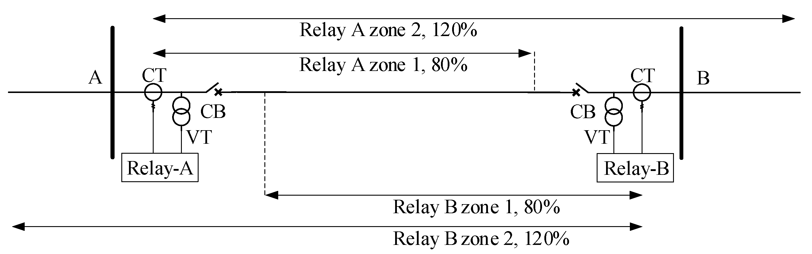
Distance protection in its usual implementation works with current and voltage measurements to determine an impedance looking into the protected line. The trip decision is then based on impedance limits, which are related to the distance to the fault on certain assumptions. The single-line diagram of a transmission line in Figure 1 shows a protection of the line between buses A and B by a distance relay at each end, with each relay having associated voltage transformers (VT), current transformers (CT) and a circuit breaker (CB).
Distance relays commonly have two or more zones defined. Zone 1 is typically not delayed, and includes faults detected as being at distances up to 80% of the length of the protected line. This provides a margin to avoid operation for faults at or beyond the remote bus. Zone 2 is typically set to trip for faults at up to 120% of the length of the protected line, but with a time delay to allow faults beyond the protected line to be cleared by closer relays. In this way, it ensures the full coverage of the line and provides some backup for faults beyond that. In practice, distance relays may be operated using more complicated zone settings, in some cases up to five zones [12]. Some of these zones may extend several buses away from the relay’s measurement point, with the consequence that a series capacitor can affect the necessary protection settings for many more relays than the two at the ends of the compensated line.
Distance relay characteristics are often described by plotting impedance in the complex plane as a resistance–reactance (RX) diagram. For a particular zone, the characteristic defines an area in this plane. A measured impedance falling within this area is taken to indicate an in-zone fault. Solid faults along the protected line correspond to a line in the plane, but a broader allowance for fault resistance, remote-end infeed, different source-angles at the ends, and uncertainties in the rapid estimation of phasors and impedance, makes it necessary to include a larger area in the characteristic. Many different distance relay characteristics are used for different purposes [13].
3. Effect of Series Capacitor on Distance Protection
Distance protection is widely used in transmission lines, but it can be strongly affected by series capacitors. This section briefly describes some special phenomena that can occur during faults in series compensated lines, and their adverse effect on distance protection. References are cited for further detail.
3.1. Voltage and Current Inversion
Voltage and current inversion are two phenomena that create problems with the security and dependability of the distance and directional elements in relays [9]. An uncompensated transmission line is inductive, so during a fault, the voltage phase angle leads the current phase angle. When a series capacitor is present, its reactance can be enough to form an overall capacitive impedance when combined with a small inductive reactance, such as the line segment between the relay and a close-in fault, or even the whole inductive reactance from source to fault. The pre-fault and during-fault phasors of voltage and current are shown in Figure 2 for two cases. Figure 2a shows the voltage inversion case, where the voltage phase changes during the fault and lags behind the current. Figure 2b shows the current inversion case, where the current phase changes abruptly and leads the voltage. The names of these two phenomena are linked with the quantity (voltage or current) that changes its phase most significantly when the fault occurs.
Voltage inversion occurs when the line becomes capacitive from the measurement point to the fault but remains inductive from the source to the fault point. This condition is shown in Equation (1), where , and are, respectively, the reactances of the source behind the relay’s measurement point, the line segment from the measurement point to the fault, and the series capacitor in the line segment:
Current inversion occurs when the line becomes capacitive from the fault point to the source. Therefore, it can be expressed by Equation (2):
Voltage inversion has to date been the most common problem in series compensated lines. The reasons include that series capacitors are usually used in systems with substantial source impedance (high ), and moderate compensation levels up to a few tens of percent of the protected line have typically been used (low ). With the trend for a wider use of series compensation and higher compensation levels, current inversion will become more of a problem.
3.2. Sub-Synchronous Oscillation
The presence of a series capacitor in a transmission line during a fault introduces low-frequency electrical oscillation that would not be present in the uncompensated system [2]. These low-frequency oscillations are usually produced for faults that are far away from the relay location. Their effect is a delay in distance relay operation. The presence of a series capacitor lowers the overall impedance of the line, so the fault current is usually higher than for an uncompensated line with the same fault. However, series compensation causes the highest fault current to be delayed after the fault due to the energy stored in the capacitor. In Figure 3, two fault currents are shown for a phase A to ground fault, 190 km from the relay for a 200 km line. The fault is applied at 0.50 s. The uncompensated line has the highest fault current right after the fault, but for the series capacitor, the highest fault current is delayed. This causes delay in the protection system operation [2]. In addition, a low-frequency oscillation can be observed in the series compensated case from 0.1 to 0.25 s.
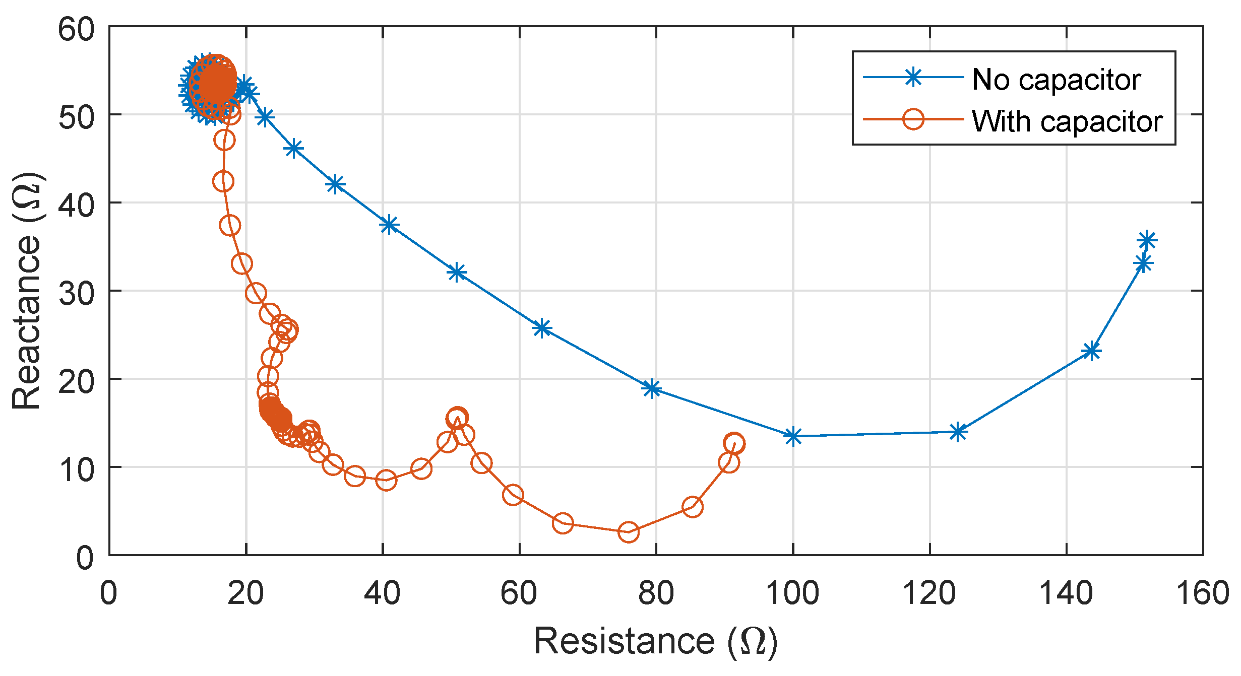
Figure 4 demonstrates the delays caused in impedance estimation in series compensated lines. The two trajectories are for the same fault in uncompensated and series compensated line. Without a series capacitor, the trajectory moves from the pre-fault position to the final operating region quickly in around 16 ms, so the distance relay may issue a trip signal within 1–2 power-frequency cycles. In contrast, with a series capacitor in the line, it takes around 80 ms to reach the same point, so the relay will be able to issue a trip signal after 4–5 power–frequency cycles. Such delays are not acceptable in high-voltage transmission line protection [14].
3.3. Sub-Synchronous Resonance Interaction
The sub-synchronous resonance (SSR) interaction is defined by the energy exchange between the electrical and mechanical systems in a power grid at one or more of the natural frequencies of the system below the synchronous frequency [15]. The four important classifications of SSR are turbine interaction (TI), induction generator effect (IGE), transient torque (TT) and sub-synchronous controller interaction (SSCI) [16]. TI is when the electrical system resonates with the mechanical modes of the turbine generator shaft system; the amplification can reach dangerous levels and damage the turbine generator system [16]. IGE occurs when the effective resistance of the electrical network and the induction generator becomes negative, giving rise to a self-excitation condition; large sub-synchronous oscillation of the current can damage the generator [16]. TT interaction happens when after large disturbances the transient torque excites natural modes of the turbine generator at sub-synchronous frequencies [16]. SSCI occurs with controllers in the power systems such as HVDC, FACTS, wind and solar power controls. These controllers may have sub-synchronous interactions in the same timescale as the series compensated systems, thereby causing stability issues [16]. These SSR interactions are generally a system-level problem and do not directly affect the protection of the compensated line itself. SSR studies should be conducted before the implementation of series compensation in a transmission system [16].
3.4. Power Swing and Out-of-Step Protection
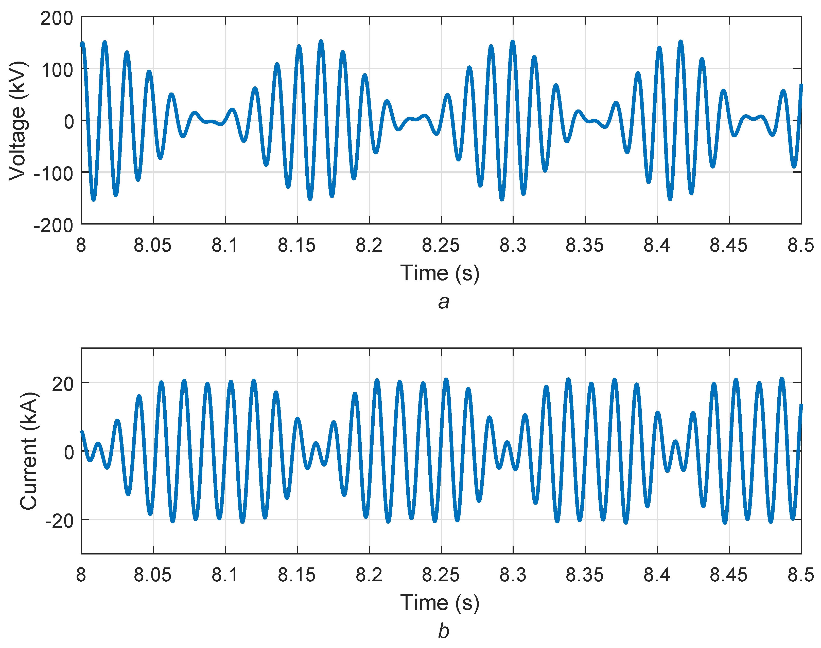
In a power system under normal operating conditions, there is a balance between load and generation and all generators run in synchronism. However, when a disturbance removes a significant amount of load or generation, the synchronised generator rotor needs to take a new angular position to create balance. Due to the higher inertia of the rotating machines, the changes are slow and oscillatory. This adjustment of rotor angles upon disturbance to reach a new stable operating point is known as power swings [17]. During power swing, the angle between different areas of the power system fluctuates [18]. Figure 5a shows the voltage and Figure 5b shows the current amplitude fluctuations in a power swing situation. The occurrence of voltage and current maxima depends on the rate of change of the power angle between two areas and is denoted as slip frequency [19]. The slip frequency can be 1–3 Hz (slow swing) and 4–7 Hz (fast swing) [20,21].
The problem with power swings is that the impedance value measured by the distance relay during a power swing can enter the operating region of the relay [17]. This can cause a false trip in an already vulnerable system and create further instability [17]. Depending on the power transfer ability of the line and rotor angle, the power swing can be stable or unstable [17]. The stable power swing will eventually reach a steady state. If the swing is unstable, the system can lose synchronism and this situation is called an out-of-step condition [22]. The protection relays should not operate during a stable power swing, which is called a out-of-step blocking (OSB) scheme [17,20]. However, if the system looses synchronism, the unsynchronised parts must be separated to prevent further damage. This is called an out-of-step tripping (OST) scheme [17,20]. This controlled system separation is done at pre-selected network locations [17,20]. Comprehensive works from the literature on the application of out-of-step protection for generators can be found in [23]. The OSB and OST schemes are extremely important as their failure can lead to system-level problems such as blackouts. In presence of a series capacitor in the transmission line, OSB and OST schemes become more challenging for the reasons mentioned in Section 3.1 and Section 3.2. The issue with power swing detection and applying any blocking or tripping scheme depends on tackling these special phenomena successfully in a series compensated line. The authors in Reference [24] evaluated different methods for detecting power swings in a series of compensated lines. In addition, as the series capacitor is related to the power transfer capacity of a transmission line, the removal of the capacitor during a fault can further jeopardize system stability.
4. Factors Influencing Effects of Series Capacitors
This section considers several design factors that significantly influence the distance protection of a series compensated transmission line. They affect the bypass of the capacitor during fault conditions, and the phenomena of voltage inversion, current inversion and sub-synchronous oscillation (SSO). Voltage inversion, current inversion and SSO influence the security and reliability of distance protection. It is therefore important to understand the relationships between these phenomena and the basic series compensation design choices.
4.1. Capacitor Bank Operation
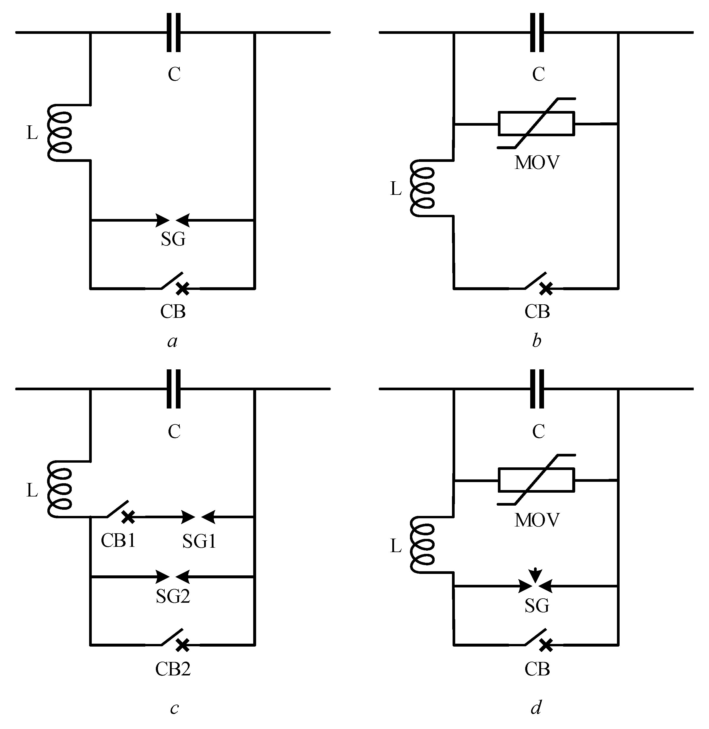
It is not economic to design series capacitors to withstand the compensated line’s fault current and consequent capacitor voltage up to the time when line protection operates. Thus, the capacitor bank needs its protection from overvoltages during fault conditions. Various arrangements of capacitor bank protection are used by different utilities. Some of the general configurations are shown in Figure 6.
In all cases in Figure 6, a circuit breaker (CB) is connected in parallel with the capacitor to bypass the capacitor when necessary. An inductor is also seen in all configurations, as the purpose of the inductor is to reduce the rise of current. Figure 6a shows a simple protection scheme using a spark gap (SG) in parallel with the capacitor. The spark gap can work as overvoltage protection and trigger to lower the voltage across the capacitor. In Figure 6c, the capacitor is protected by two levels of spark gaps. Figure 6c shows a configuration where the capacitor is protected with a metal oxide varistor (MOV). The highly non-linear characteristic of the MOV offers high resistance in normal conditions and low resistance during faults. At lower voltages, the MOV gives a high resistance, and all current flows through the capacitor, but when higher voltages start to build up across the capacitor, the MOV gives a low resistance path to take current away from the capacitor. The MOV’s protective level is usually set above the maximum voltage expected during power swing or overload condition [25] so that it only conducts during a fault. The most common method is as shown in Figure 6d, where the protection circuit connected in parallel with the capacitor includes a metal oxide varistor, spark gaps and bypass circuit-breaker, along with an inductor to limit the transient current [2]. The spark gap is triggered to bypass the MOV when pre-set limits are reached for the MOV’s absorbed power or its cumulative absorbed energy over a short time [25].
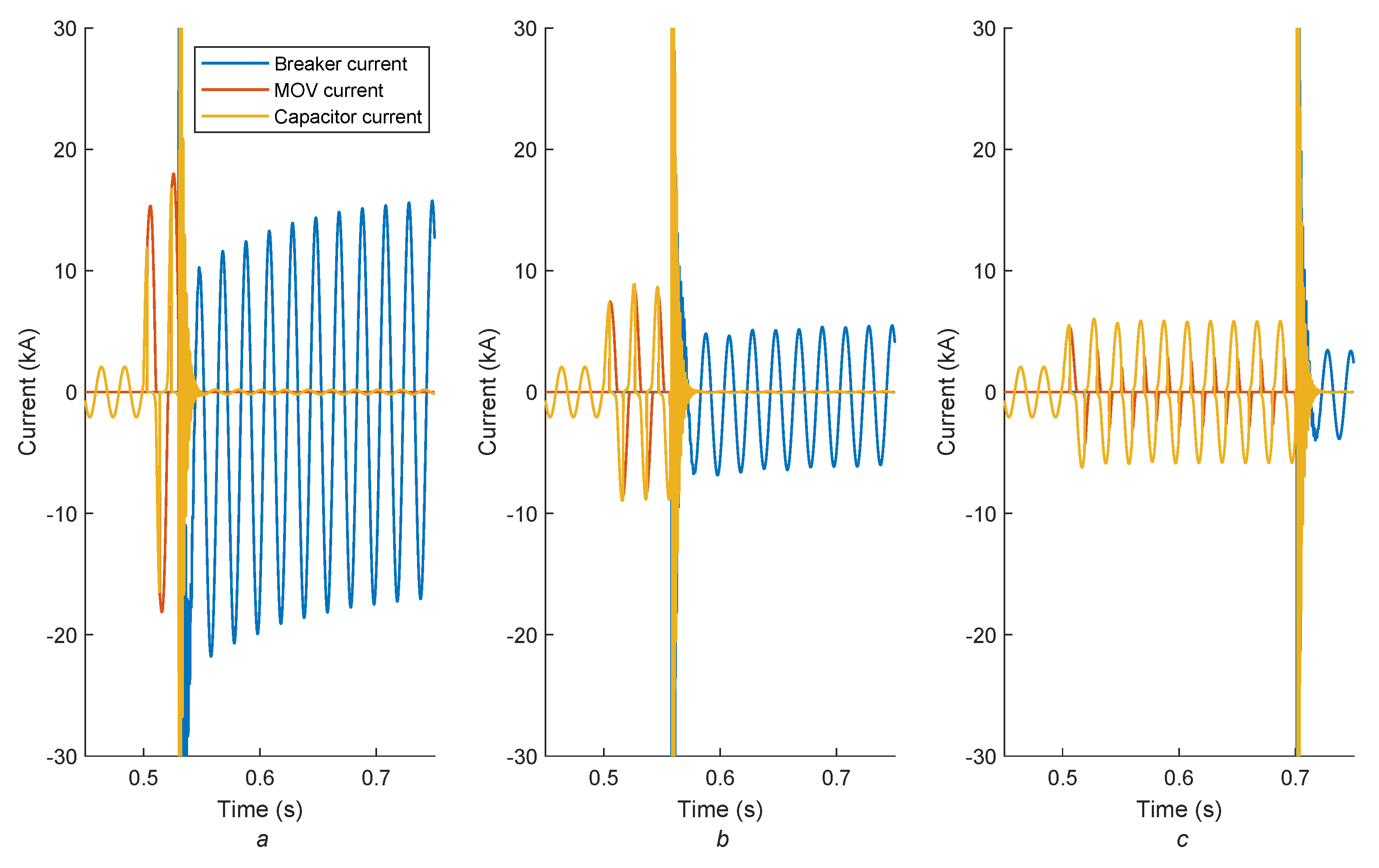
Depending on the fault condition, there are three possibilities for how current flows through the MOV and capacitor. These three cases are shown in Figure 7. For a high fault current, as shown in Figure 7a, the MOV will start conducting immediately after the fault inception and the spark gap will be fired, taking the capacitor out of the fault loop. For a moderate fault current, both the MOV and capacitor will conduct the fault current until the MOV energy absorption has reached its limit—as shown in Figure 7b. For a low fault, the MOV may not conduct current at all and the fault current goes through the capacitor entirely as shown in Figure 7c. The MOV operation dictates the value of capacitive reactance in the fault loop. Therefore, the first challenge for the protection scheme in a series compensated line is to determine whether the series capacitor remains in the fault loop: the highly non-linear behavior of the MOV makes this difficult.
4.2. Source Impedance
The source impedance is the equivalent impedance of the power system connected to a terminal of the transmission line. For line protection, the impedance of the protected line is a relevant reference point for defining source strength, so the source-to-line impedance ratio (SIR) is widely used [26]; a stronger source gives a lower SIR. The amplitude of the fault current is also dependent on SIR, at higher SIR the fault current is lower and at lower SIR, the fault current is higher [27]. Voltage inversion is related to the overall impedance of the line from the fault to the relay being capacitive. Current inversion is related to overall impedance from the fault to the source being capacitive. Therefore, the source strength plays an important part in determining the inversion conditions.
4.3. Fault Impedance
Fault impedance may be composed of three elements: electric arc, tower grounding and the object in the fault path [28]. Traditionally, an electric arc is considered resistive. The effective grounding impedance of the tower is mainly resistive, but its inductive proportion is higher in the presence of ground wires [28]. The impedance of the object in the fault path can vary greatly depending on the circumstances, but generally, it is resistive [28]. For transmission line protection, the impedance of a line to ground fault is considered to consist of the arc resistance and the effective grounding resistance of the tower [28]. Fault impedance affects the fault current, thus affecting MOV operation in a series compensated line. A higher fault impedance results in a lower current, which may cause MOV operation to be later or not to happen.
4.4. Compensation Level
The compensation level k is defined in Equation (3). It is the proportion of the inductive reactance of the line that is compensated by the capacitive reactance of the series capacitor. It is usually expressed in percent:
Higher levels of compensation decrease the overall impedance of the line, and thus further allowing even more current to flow within the constraints imposed by system stability or the thermal limits of parallel lines. For example, in an upgrade of a series compensated line from 28% to 70% compensation, the nominal current rating of the line increased from 1283 A to 1600 A (511 MW–637 MW power) [9]. However, higher compensation levels generally increase the troubles that series compensation poses for protection. A higher capacitive reactance increases the probability of voltage and current inversion in the line [10], and the voltage across the series capacitor is higher for a higher level of compensation [29].
4.5. Capacitor Bank Position in the Line
The location of the capacitor affects the voltage profile of the line: the voltage varies smoothly along the line and undergoes a sudden change at the capacitor [3,29]. The capacitor position also changes the line segment where fault would cause voltage or current inversion or sub-synchronous oscillation.
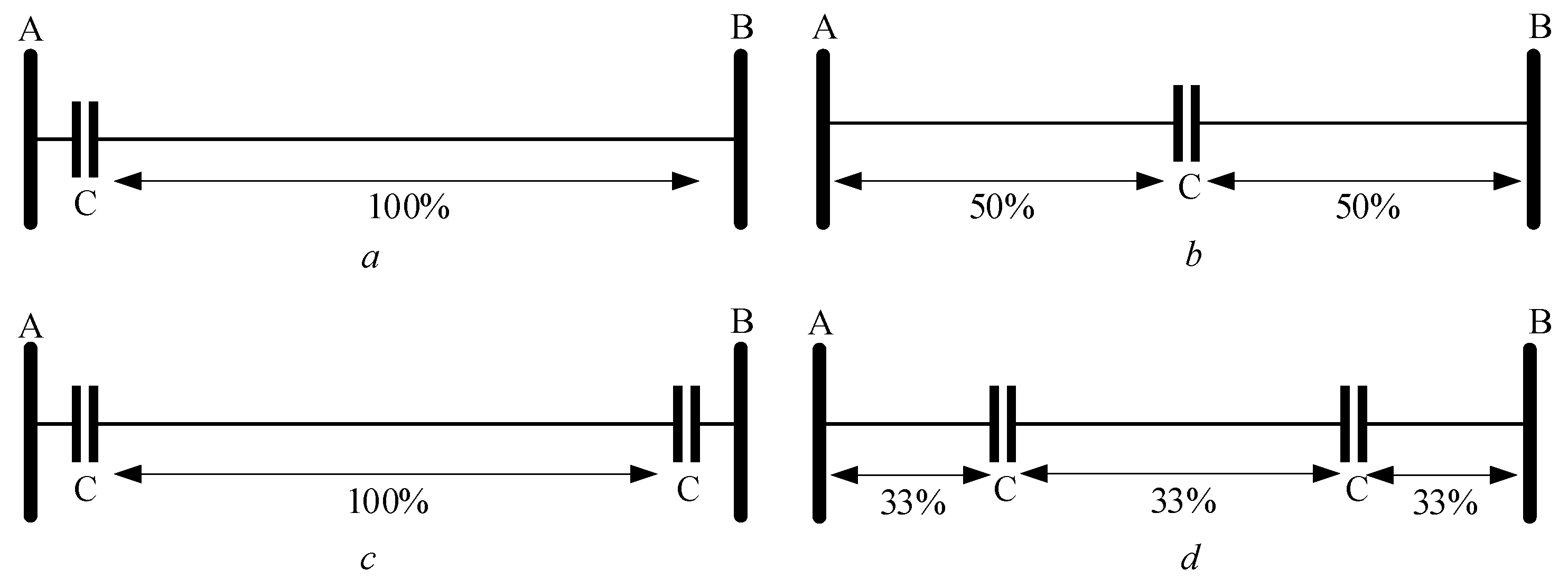
The four general positions of the capacitor bank in the transmission line are shown in Figure 8. Capacitor banks can be placed in one end or both ends of the line as shown in Figure 8a,b, or within the line, at for example, a half or third of the line length as shown in Figure 8c,d [3].
From the perspective of voltage profile, placing capacitors in the middle of the line is most effective [29]. In practice, the location is dictated by considerations of the specific project. Line-end compensation is more common in existing transmission lines [2]. For new lines, line-end compensation makes designing the protection scheme easier [30]. However, line-end installations can increase cost due to the requirement of changing relays at nearby substations due to the spread of voltage inversion beyond the compensated line [30]. Contrariwise, mid-line installation requires building a substation in the middle of the line and makes the protection more difficult, but potentially reduces the cost of relay replacement in nearby substations [30].
4.6. Current and Voltage Transformer Position
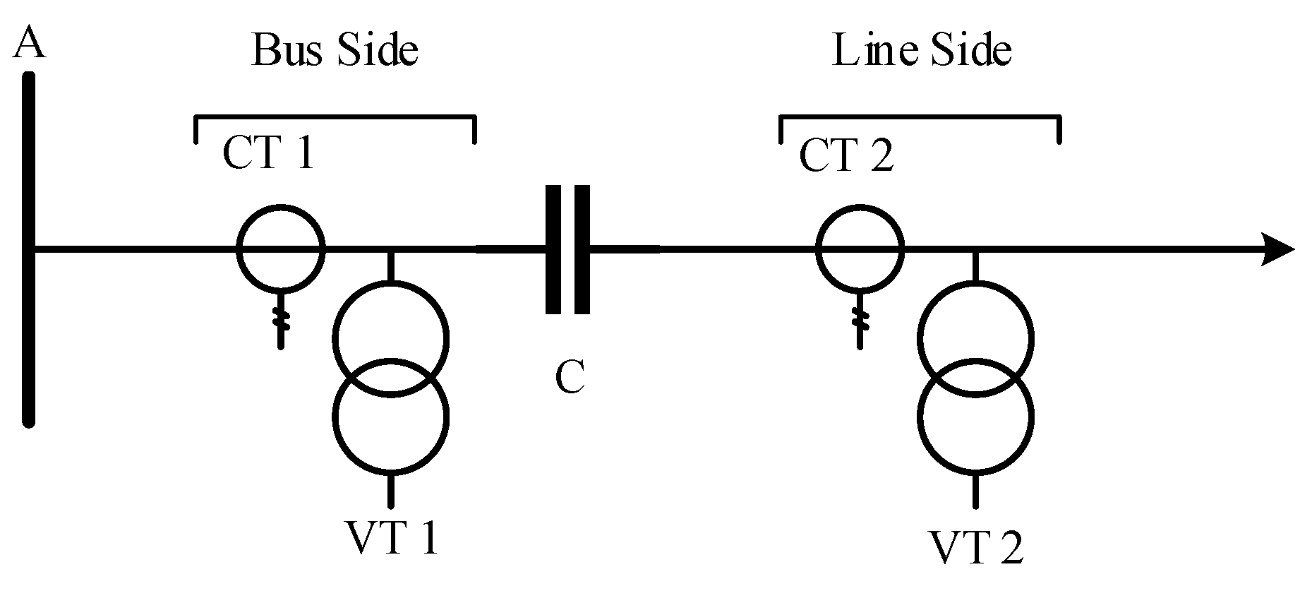
The position of instrument transformers relative to the series capacitor is important, especially in the case of line-end compensation. Figure 9 shows different positions of the current transformer (CT) and voltage transformer (VT) relative to a line-end series capacitor. It is assumed that the cost of equipment, space and reliability renders a scheme with instrument transformers at both sides of the capacitor uneconomic. Distance protection uses voltage measurement, so it is affected by the location of the VT [2], particularly concerning voltage inversions. If the voltage transformer is placed after the series capacitor (line side), then the relay will not experience voltage inversion for the faults in the forward direction, but it may experience voltage inversion for the faults in the reverse direction [2,31]. If instead, it is placed before the series capacitor (bus side), this relation of inversion to fault direction is swapped.
4.7. Protection of Adjacent Lines
Installing a series capacitor in a transmission line potentially affects the protection of adjacent lines as well a the compensated line. During fault conditions, voltage and current inversion phenomena spread in the connected lines as well. In practice, this can mean replacing or re-configuring older relays in nearby substations when a series capacitor is installed in in a line [2,9,30]. Distance relays in adjacent lines can be influenced by the capacitive reactance of the series capacitor during a fault [3]. If an adjacent line is short and has lower inductive reactance than the series capacitor, the concern is extended to the remote bus of the adjacent line and even to two more line sections [3]. Adjacent line protection is particularly challenging at the end line compensation [3]. Considering the above, the protection of a series compensated line should be a system-level study, considering not only the compensated line, but the adjacent lines as well.
5. Methods in Use by Relay Manufacturers
A review was carried out to investigate the methods employed by different relay manufacturers for the distance protection of series compensated lines. The manufacturers of line protection relays were identified, and the relay manuals from these manufacturers were studied. For those relays that were declared as able to work with series compensated lines, the provided information about their solutions for this application were studied. The solutions presented below are what was compiled from these publicly available documents from the manufacturers; they are not expected to be exhaustive, as further optimizations not described in the manuals may be embedded in the relays. On the transient-based protection side, ref. [32] is an incremental quantity distance protection based on voltage and current signals that work with series compensated lines.
5.1. Voltage Inversion
Voltage inversion is the most common problem in series compensated lines. It can cause directional errors, as the phase of voltage is changed during a fault. To solve voltage inversion problems, memory voltage polarization using the pre-fault voltage is used in many relays [33,34,35,36,37,38,39,40].
The voltage phase angle is usually used as the reference to compare the other quantities in protection relays. During voltage inversion, this phase changes abruptly, potentially leading to an incorrect decision if used as a reference or polarizing value. Therefore, in a series compensated line, the voltage phasor is kept in memory for a few cycles all the time. When a fault occurs, the pre-fault voltage phasor in the memory is used in the relay operation. This method is generally called memory voltage polarization. The implementations vary from different manufacturers.
Memory voltage is permanently used in the directional element in one of these implementations [33]. Here, the memory voltage is used until the positive sequence voltage is restored to its normal value or until the time of 100 ms is exceeded. If the current is still above the set value after 100 ms after a fault detection, then issued trip commands are kept and if the fault was detected in reverse, the measuring element in reverse remains in operation. If the current decreases below the set value before 100 ms of fault detection, then the memory is reset until the positive sequence voltage exceeds 10% of the base value. In [34], the memory duration is set to longer than the slowest fault clearing time for the reverse fault, as this guarantees that the distance element would not pick up on reverse faults during voltage inversion. In [35], memory voltage is always used for three-phase faults. A positive sequence voltage memory buffer stores the voltage from two cycles before the fault inception as determined by a fault detector. The duration of the memory voltage can be determined by a setting but is typically set to four cycles. To prevent incorrect trips at the end of the memory voltage time, the relay incorporates a logic that allows transiently blocking all directional units in the forward direction once it is detected that the fault is in a reverse direction. In [36], the duration of memory validity is determined by a setting, from 0 s to 10 s with a step of 10 ms. In [38], the voltage drop on the series capacitor is estimated and subtracted from the measured zero-sequence voltage, and the resulting voltage is used in the directional characteristic of fault protection. In [40], positive sequence voltage from two cycles before the fault is used to polarize the distance protection.
5.2. Current Inversion
A solution to deal with current inversion is less commonly found in relay manufacturer manuals. One that does describe a solution is [34], which uses a multi-input comparator approach. In the current inversion condition, the distance elements are secured on reverse faults, using multiple conditions involving fault loop and negative- and zero-sequence currents, and the memory voltage is checked before issuing a trip command [34]. During the current inversion, the relays may not operate for a short period, so the manufacturer recommends using high-speed over-current protection for direct tripping [34].
5.3. Sub-Synchronous Oscillation
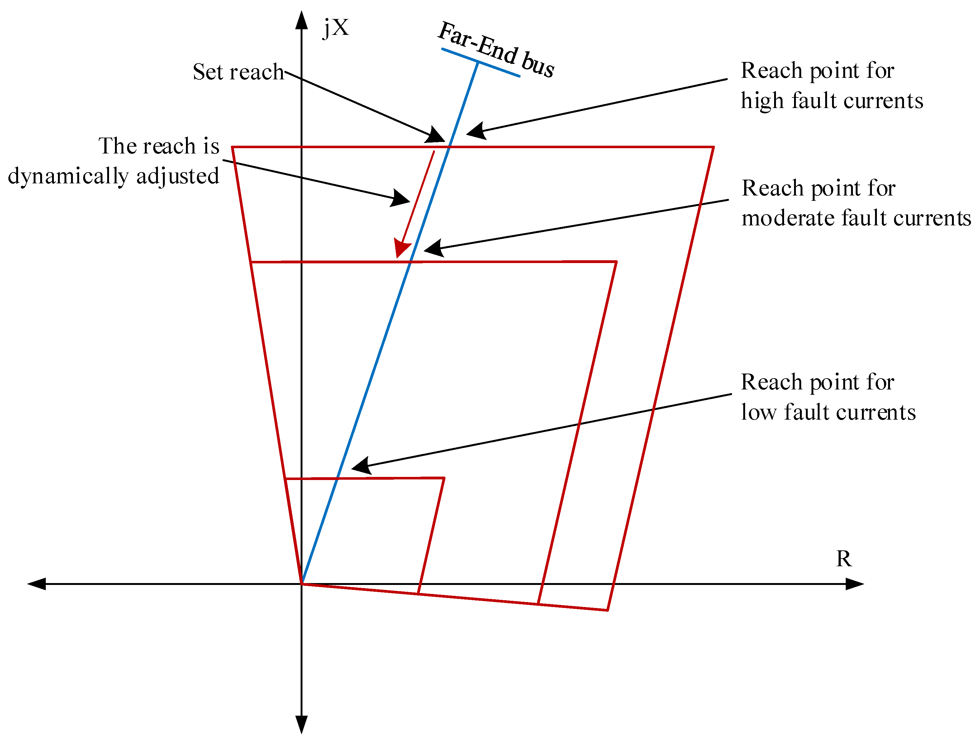
One method to tackle the sub-synchronous oscillation issues is harmonic filters, which are used in [41]. Some relays use adaptive characteristics [34,41]. In one relay, the tripping boundary is adjusted using the current magnitude through the series capacitor bank [34]. The reach is reduced to cope with both steady-state and transient over-reach. For a large degree of compensation and low current faults, the transient over-reach can be very high, which means that fast distance protection is not achievable [34]. The adaptive reach is shown in Figure 10. For high current faults, the reach is the same as the pre-set value of around 80–85% of the line. To mitigate the transient over-reach as the currents get lower, the reach is adjusted. In the case of very low current faults, the reach can be as low as 10–20% of the line [42].
6. Implementation Examples
Series compensated lines are common across different parts of the world. Series capacitors are generally the simplest and cost-effective way to increase the power transfer ability of a transmission line. It is difficult to obtain an exact estimation of the cost of series capacitor implementation versus building a new line, as projects like this have many variables that can influence the cost and prices are often confidential between the utility and manufacturer. In other works, it is often mentioned that the cost for series capacitor implementation is 10% of building a new line [2,43]. In [44], the effective cost of the new line was calculated to be USD 400–1000/MW-mile, while the cost of series compensation was calculated to be USD 45–180/MW-mile. In [45], the annual operation and maintenance (O&M) cost for a new line is calculated to be USD 540,000, while the O&M cost for series compensation is calculated to be USD 48,000. These numbers also align with around a 10% cost estimation mentioned above. However, as mentioned in the Section 4.5, the site selection of the series capacitor often dictates the cost of series compensation.
An incorrect site selection can increase the overall cost of series compensation. For example, Entergy Gulf States Texas completed the installation of a series capacitor on a 230 kV line in 2001, the capacitor which was installed in an existing substation to reduce the cost of building a new substation and simplified protection scheme [30]. However, this substation had many other substations around where relays experienced voltage inversion after the capacitor was installed [30]. This resulted in relay replacement in 18 line terminals and settings change in 17 more line terminals with an additional cost of USD 600,000 [30]. This prompted the utility to conduct a detailed pre-study before implementing another series capacitor in a new line. The additional cost incurred is related to the number of relay terminals affected by the voltage and current inversion. In three cases that were considered, 27, 23 and 5 relay terminals were affected and the estimated project cost for relay replacement/setting change were USD 980,000, USD 850,000 and USD 350,000 [30], respectively. This type of study must be conducted before the implementation of series capacitors in a power grid to achieve a cost-effective solution.
Utilities all over the world have implemented various levels of compensation and used different protection methodologies for their series compensated lines. In this section, some methods used by utilities to protect their series compensated lines were compiled to obtain a picture of the protection philosophy implemented in the field in this domain.
To improve the power quality in their network, Eskom planned to strengthen the Empangeni 400 kV network by relocating the existing series capacitors from another part of the network to the area considered [46]. Three feeders were planned for series compensation, two with 70% and one with 50% compensation, and for a protection study, two scenarios were considered, considering capacitors in different ends of the lines [46]. In the protection studies, both voltage and a current inversion were observed in the proposed network configurations [46]. None of the existing relays were equipped with polarizing memory to handle voltage inversion [46]. It was identified that distance protection was not suitable for the proposed network configurations, without increasing the risk of incorrect operations [46]. It was concluded that the cost and added risk did not justify the installation of the proposed capacitors [46]. Finally, a new unit-type protection scheme and relay replacements were recommended [46].
In India, a program was started for the installation of series capacitors to enhance the capacity of the existing lines and build new high capacity lines with series capacitors [2]. In both old and new lines, compensation levels commonly range from 27% to 70%, with 40% being the most frequently found level [2]. The present practice followed in India is to conduct project-specific testing by modeling the system using EMTP generated files. Faults in different line locations are simulated, then the voltage and current waveforms are obtained for bus-bars at different relay locations, and are used to analyze protection performance [2]. One of the first proposed series compensated lines in India was the Kanpur–Ballabhgarh 400 kV line, with 35% series compensation. The protection study indicated the need to replace conventional distance protection relays with numerical relays and series compensation support at the Ballabhgarh end, and to change the zone setting of the relay at the Kanpur end, in addition to the adoption of a permissible over-reach tripping scheme [47].
In the east–central tie lines in Saudi Arabia, a series compensation of 50% is provided in the middle of the line. The distance protection uses memory voltage for directional discrimination in both ends, and zone 1 is set at 32.5% of the line length from both ends [2].
In the São João Do Piauí substation of Companhia Hidro Elétrica do São Francisco (CHESF) in Brazil, both the incoming and outgoing 500 kV transmission lines are 70% are series compensated [48]. A distance protection relay is used for protection [48]. The relay was accompanied by permissive over-reaching transfer trip (POTT), directional comparison pickup, unblocking/blocking, pilot wire comparison, reverse interlocking, direct under-reaching transfer trip (DUTT), permissive under-reaching transfer trip (PUTT) and weak infeed protection [48]. In the real-time digital simulation, a total fault elimination time below 100 ms was observed in the worst case, which was considered satisfactory by the utility [48].
In Venezuela, a protection study was conducted for five series capacitor compensated lines. Three of these were parallel 400 kV lines with 24–26% compensation, and the others were 400 kV with 51% compensation and 765 kV with 44% compensation [49]. Voltage inversion and sub-synchronous oscillation were present in all five lines during fault conditions [49]. It was necessary to replace the existing protection relays in some cases, and in all cases, zone 1 had to be considerably reduced and zone 2 increased. Permissive over-reaching transfer trip (POTT) had to be implemented in all 400 kV lines, inducing a greater dependency on communication equipment [49].
BC Hydro in Canada had 11 series compensated lines at 500 kV as of 2009 [50]. In their network, they experienced voltage and current inversion and zone 1 over-reach [50]. Distance protection is used in these lines, based on negative sequence impedance and source impedance depending on the line configuration [50]. Auto-reclosing challenges are mitigated by using time delays and coordination between line terminals [50]. The challenges associated with the sub-synchronous oscillation problem in the BC Hydro network require further investigation to find appropriate solutions [50]. Hydro-Québec TransÉnergie (HQT), another system operator in Canada, has implemented series compensation in their system since the 1990s [51]. The compensation level ranges from 20–44%, and the series capacitors are located variously at the line end or middle in the different lines [51]. Voltage inversion is present in their system, but not current inversion [51]. The protection scheme was developed with extensive real-time simulation. The main protection schemes used are communication dependent, and the backup protection is distance protection using a modified lens-type characteristic to avoid being sensitive to load and power swings [51].
In the United States, Entergy installed a series capacitor in a 230 kV line. The series capacitor was installed at the end of the line, however, there were many other substations close to the series capacitor. Thus, the voltage inversion from the series capacitor during fault affected all the older generation relays in the surrounding substations. This resulted in relay replacements at 18 line terminals and settings modification at 17 more terminals [30]. Entergy later built another 66 km 230 kV line with 70% series capacitor compensation. After a protection study, the capacitor bank was recommended to be installed in the middle of the line to minimize the effect of voltage inversion on surrounding relays [30]. Due to voltage inversion, a capacitor bank at one end would have required replacing or modifying 27 relays, and at the other end, it would have required replacing or modifying 23 relays; in contrast, installing the capacitor bank in the middle of the line required replacing or modifying only five relays [30]. For protection, a direct fiber optic communication-assisted current differential relay was selected due to the presence of voltage inversion [30] and the consequent difficulty of applying for distance protection. Pacific Gas & Electric (PG&E), another system operator in the United States, has series compensated lines in its 500 kV transmission network [52]. Real-time digital simulation (RTDS) testing has been used to study the protection scheme extensively and has shown that series capacitors cause over-reach due to sub-synchronous oscillation and undesired operation due to voltage inversion [52]. The main protection schemes are communication-dependent permissive over-reach transfer trip (POTT). Additionally, advanced series compensation logic and memory voltage polarization are used to counter the above problems. Zone 1 is also reduced in compensated lines [52]. In another utility in the United States, Idaho Power, upgrading two 230 kV lines from 28% to 70% compensation was completed [9]. The capacitor banks were installed in in-line terminals. Both voltage and current inversion possibility were identified in the protection study. This eliminated the possibility of using distance protection even with memory voltage polarization [9]. The current differential protection was chosen as a protection method, but as there was the possibility of current inversion, the phase differential pickup, restraint radius and blocking angle were decreased [9]. Current inversion also imposed a higher requirement on the communication channels (symmetrical) and current transformers (no saturation) [9].
As can be seen from these paragraphs above, the protection of series compensation lines is challenging. Voltage and current inversion cause a major challenge in protection design. In cases where distance protection is used, zone 1 had to be reduced. In cases where differential protection is used, the utilities need additional investment for building communication channels. Some of the projects from the paragraphs above are summarized in Table 1.
7. Patent Activity Overview
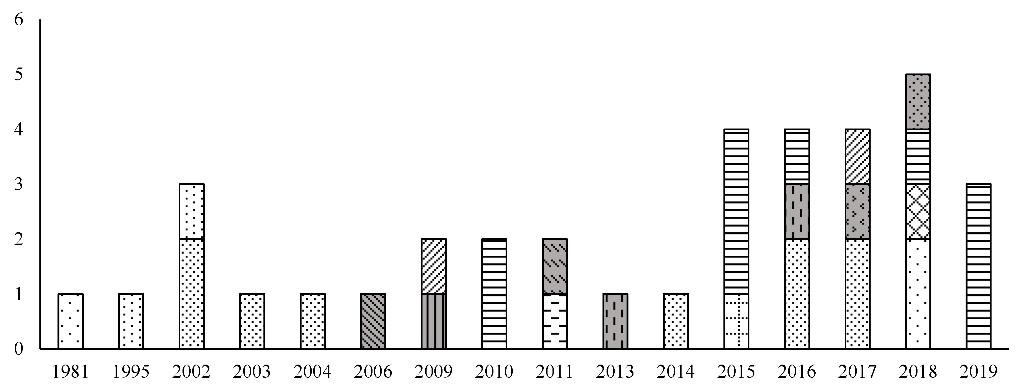
For further perspective on developments from the relay manufacturers and utilities, an intellectual property right (IPR) search was conducted through Derwent Innovation [11]. A total of 36 patents were found in the database, for the years from 1980 to 2019, with search terms focused on the protection of series compensated transmission lines. The number of patents in different years from different organizations are shown in Figure 11. The fill patterns in the bars in Figure 11 represent different organizations. The grey shaded bars represent patents filed from universities and research institutes. It is observed that most of the patents are from relay manufacturers and power transmission utilities. The IPR search showed an increased number of patents on series compensated line protection in the last five years, starting from 2015. This indicates an increased interest in the topic from different stakeholders.
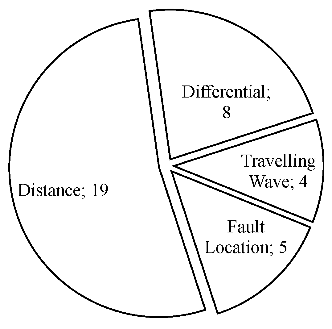
To understand the methods employed in the identified patents, all the found patents were studied. The goal was to understand the techniques employed to solve the protection of series compensated lines. Figure 12 shows the categories of patents. Among these patents, more than half (19) concern distance protection. These are focused on improving the estimation of impedance during faults to identify the fault location in the line. Within these, the earliest ones are based on solving equations where the voltage and current measurements are used to solve pre-set equations to detect fault conditions. Of later interest was the use of sequence components and voltage compensation for the capacitor bank. In recent years, patents on distance protection are based on adaptive parameters, where the relay dynamically changes parameters for changing system conditions to improve fault detection. A further eight patents concern differential protection; these were published after 2010 and are mostly based on sequence components. Differential protection requires fast reliable communication between two terminals of the protected line. This increasing number of differential protection in the last decade is consistent with the improved communication technology in the last decade. Time domain methods have a higher requirement on measurement, in terms of sampling rate. With the improvement of measurement rate, in more recent years, there have been four patents based on traveling waves, mainly concerned with methods for detecting the arrival of a fault wave at a measurement point. The remaining patents deal with fault-location in series compensated lines.
8. Industry Trends
Section 6 and Section 7 can be used to understand the trends in this domain from an industry perspective. It can be observed that higher levels of series compensation are installed in the transmission network. The examples presented in Section 6 indicate that it can be observed that differential protection is being used for the protection series compensated line as well, especially with higher levels of compensation (70%). If distance protection is used, the reach of zone 1 has to be significantly reduced. Higher levels of compensation will cause worse cases of voltage inversion, current inversion and oscillation, which make the distance protection unreliable and slow [10]. In these cases, differential protection presents an alternative. As higher levels of series compensation are implemented throughout the world, it was expected to see an increasing number of communication or time-domain-based protection, such as differential and transient-based protection instead of typical distance protection. This trend in the development of communication or time-domain schemes was further confirmed from the patent overview. In the last decade, most patents involving the protection of series compensated lines concern differential or traveling wave-based methods. The reason for this change may be two-fold. Firstly, there has been tremendous development in communication technologies in recent decades; it is now possible to achieve secure, reliable communication for long transmission lines, which aids the implementation of differential protection. Secondly, the processing power and measurement devices such as voltage and current transformers have also been improving, leading to the possibility of having a higher sampling rate of measurement and faster calculations in relays, leading to the use of time-domain-based solutions. These points lead to the conclusion that future series compensated lines with high levels of compensation are likely to be protected using communication-aided or time-domain calculation-based methods.
9. Concluding Remarks
The application of distance protection to series compensated lines is influenced by many design factors, such as capacitor bank position and operation, impedance, compensation level, CT/VT position, etc. The choice of these design factor dictates the choice of protection methods and influences the levels of voltage inversion, current inversion and oscillation. The trend of increasing levels of compensation was also identified. The survey of industrial practice indicates that many manufacturers use memory voltage polarization to counter voltage inversion, however, the solutions for current inversion and SSO are less common. Current inversion and SSO increase with higher levels of compensation, which implies a further problem at high compensation levels. The summary of implementation examples from different parts of the world also shows that at higher compensation levels, there is a tendency to use differential protection. If distance protection is used, zone 1 reach has to be reduced significantly to reduce mal-operation. The patent search shows that there is an increase in the number of patents filed in the last decade about the protection of series compensated lines. This suggests increasing interest in this relatively old topic from different stakeholders. The renewed interest in the topic may be attributed to the increasing requirement on transmission lines due to renewable energy and market deregulation. Most patents from the last decade are related to differential and time-domain-based protection. The presented manufacturer solutions, implementation examples and patent overview point to a trend of more communication-aided or time-domain-based protection for series compensated transmission lines.
Author Contributions
Conceptualization, M.T.H. and N.T.; methodology, M.T.H.; validation, M.T.H. and N.T.; formal analysis, M.T.H.; investigation, M.T.H.; data curation, M.T.H.; writing—original draft preparation, M.T.H.; writing—review and editing, N.T.; visualization, M.T.H.; supervision, N.T.; project administration, N.T.; funding acquisition, N.T. All authors have read and agreed to the published version of the manuscript.
Funding
This work was funded through SweGRIDS, by the Swedish energy agency, Hitachi ABB Power Grids and the Swedish transmission network operator Svenska kraftnät.
Institutional Review Board Statement
Not applicable.
Informed Consent Statement
Not applicable.
Data Availability Statement
Not applicable.
Conflicts of Interest
The authors declare no conflict of interest.
Abbreviations
The following abbreviations are used in this manuscript:
| SSR | Sub-synchronous resonance |
| TI | Turbine interaction |
| IGE | Induction generator effect |
| TT | Transient torque |
| SSCI | Sub-synchronous controller interaction |
| HVDC | High-oltage direct current |
| FACTS | Flexible alternating current transmission systems |
| OSB | Out-of-step blocking |
| OST | Out-of-step tripping |
| SSO | Sub-synchronous oscillation |
| MOV | Metal oxide varistor |
| CB | Circuit breaker |
| SG | Spark gap |
| SIR | Source-to-line impedance ratio |
| CT | Current transformer |
| VT | Voltage transformer |
| O&M | Operation and maintenance |
| POTT | Permissive over-reaching transfer trip |
| DUTT | Direct under-reaching transfer trip |
| PUTT | Permissive under-reaching transfer trip |
| RTDS | Real-time digital simulation |
References
- Saied, M.M. Optimal Long Line Series Compensation. IEEE Trans. Power Deliv. 1986, 1, 248–253. [Google Scholar] [CrossRef]
- CIGREWorking Group B5.10. Protection, Control and Monitoring of Series Compensated Networks; Technical Report; CIGRE: Paris, France, 2010. [Google Scholar]
- Miller, J.; Brunet-Watson, M.; Leighfield, J. Review of Series Compensation for Transmission Lines; Technical Report; PSC North America: Westborough, MA, USA, 2014. [Google Scholar]
- Korot, D.; Marken, P.; Bock, L. The next fifty years of series capacitors—And the last eighty-six. In Proceedings of the 2014 IEEE PES T&D Conference and Exposition, Chicago, IL, USA, 14–17 April 2014; pp. 1–5. [Google Scholar] [CrossRef]
- Nitsch, J.; Krewitt, W.; Langniss, O. Renewable Energy in Europe. In Encyclopedia of Energy; Cleveland, C.J., Ed.; Elsevier: New York, NY, USA, 2004; pp. 313–331. [Google Scholar] [CrossRef]
- Borlase, S. (Ed.) Smart Grids: Infrastructure, Technology, and Solutions, 1st ed.; CRC Press: Boca Raton, FL, USA, 2012. [Google Scholar]
- El-Marsafawy, M. Economical design of series capacitor compensation for long power transmission systems. Int. J. Electr. Power Energy Syst. 1991, 13, 321–329. [Google Scholar] [CrossRef]
- Hoq, M.T.; Wang, J.; Taylor, N. Review of recent developments in distance protection of series capacitor compensated lines. Electr. Power Syst. Res. 2021, 190, 106831. [Google Scholar] [CrossRef]
- Bakie, E.; Westhoff, C.; Fischer, N.; Bell, J. Voltage and current inversion challenges when protecting series-compensated lines—A case study. In Proceedings of the 2016 69th Annual Conference for Protective Relay Engineers (CPRE), College Station, TX, USA, 4–7 April 2016; pp. 1–14. [Google Scholar] [CrossRef]
- Hoq, M.T.; Wang, J.; Taylor, N. Impact of High Levels of Series Compensation on Line Distance Protection. In Proceedings of the 15th International Conference on Developments in Power System Protection (DPSP), Liverpool, UK, 9–12 March 2020. [Google Scholar]
- Derwent Innovation. Available online: https://clarivate.com/derwent/solutions/derwent-innovation/ (accessed on 7 May 2021).
- Abboud, R.; Bell, J.; Smyth, B. Considerations and Benefits of Using Five Zones for Distance Protection; Schweitzer Engineering Laboratories: Pullman, WA, USA, 2019; p. 12. [Google Scholar]
- Sarwade, A.N.; Katti, P.K.; Ghodekar, J.G. Advanced distance relay characteristics suitable for dynamic loading. In Proceedings of the 2010 Conference Proceedings IPEC, Singapore, 27–29 October 2010. [Google Scholar] [CrossRef]
- Bonneville Power Administration. Technical Requirements for Interconnection to the BPA Transmission Grid; Technical Report; BPA: Portland, OR, USA, 2016.
- Subsynchronous Resonance Working Group. Reader’s guide to subsynchronous resonance. IEEE Trans. Power Syst. 1992, 7, 150–157. [Google Scholar] [CrossRef]
- CIGRE Working Group C4/B5.41. Challenges with Series Compensation Applications in Power Systems When Overcompensating Lines; Technical Report; CIGRE: Paris, France, 2021. [Google Scholar]
- Paithankar, Y.G.; Bhide, S.R. Fundamentals of Power System Protection, 2nd ed.; PHI Learning Private Limited: Delhi, India, 2013. [Google Scholar]
- Blackburn, J.L.; Domin, T.J. Protective Relaying: Principles and Applications, 4th ed.; CRC Press: Boca Raton, FL, USA, 2014. [Google Scholar]
- Brahma, S.M. Use of wavelets for out of step blocking function of distance relays. In Proceedings of the 2006 IEEE Power Engineering Society General Meeting, Montreal, QC, Canada, 18–22 June 2006. [Google Scholar] [CrossRef]
- Tziouvaras, D.; Hou, D. Out-of-step protection fundamentals and advancements. In Proceedings of the 57th Annual Conference for Protective Relay Engineers, College Station, TX, USA, 1 April 2004; pp. 282–307. [Google Scholar] [CrossRef]
- Mechraoui, A.; Thomas, D.W.P. A new blocking principle with phase and earth fault detection during fast power swings for distance protection. IEEE Trans. Power Deliv. 1995, 10, 1242–1248. [Google Scholar] [CrossRef]
- Jacome, Y.; Henville, C.F. Setting Out-of-Step Blocking or Tripping Using Dynamic Simulations; Schweitzer Engineering Laboratories: Pullman, WA, USA, 2011. [Google Scholar]
- Power System Relaying and Control Committee Report of Working Group J5. Application of Out-of-Step Protection Schemes for Genrators; Technical Report; IEEE: New York, NY, USA, 2020. [Google Scholar]
- Esmaeilian, A.; Ghaderi, A.; Tasdighi, M.; Rouhani, A. Evaluation and performance comparison of power swing detection algorithms in presence of series compensation on transmission lines. In Proceedings of the 2011 10th International Conference on Environment and Electrical Engineering, Rome, Italy, 8–11 May 2011; pp. 1–4. [Google Scholar] [CrossRef]
- Goldsworthy, D.L. A Linearized Model for Mov-Protected Series Capacitors. IEEE Trans. Power Syst. 1987, 2, 953–957. [Google Scholar] [CrossRef]
- Thompson, M.J.; Somani, A. A tutorial on calculating source impedance ratios for determining line length. In Proceedings of the 2015 68th Annual Conference for Protective Relay Engineers, College Station, TX, USA, 30 March–2 April 2015; pp. 833–841. [Google Scholar] [CrossRef]
- Sanaye-Pasand, M.; Jafarian, P. An Adaptive Decision Logic to Enhance Distance Protection of Transmission Lines. IEEE Trans. Power Deliv. 2011, 26, 2134–2144. [Google Scholar] [CrossRef]
- Andrade, V.D.; Sorrentino, E. Typical expected values of the fault resistance in power systems. In Proceedings of the 2010 IEEE/PES Transmission and Distribution Conference and Exposition: Latin America (T&D-LA), Sao Paulo, Brazil, 8–10 November 2010; pp. 602–609. [Google Scholar] [CrossRef]
- Anderson, P.M.; Farmer, R.G. Series Compensation of Power Systems; PBLSH! Inc.: Encinitas, CA, USA, 1996. [Google Scholar]
- Saia, N. The importance of site selection for series compensation. In Proceedings of the 58th Annual Conference for Protective Relay Engineers, College Station, TX, USA, 5–7 April 2005; pp. 201–210. [Google Scholar] [CrossRef]
- Shah, S.A.U. The Impacts of Series Compensated EHV Lines on Distance Protection, and a Proposed New Mitigation Solution. Master’s Thesis, KTH The Royal Institute of Technology, Stockholm, Sweden, 2017. [Google Scholar]
- Schweitzer Engineering Laboratories, Inc. SEL-T400L Time-Domain Line Protection Datasheet. 2017. Available online: https://selinc.com/products/T400L/docs/ (accessed on 7 May 2021).
- ABB. REL670 2.1 IEC Application Manual Line Distance Protection. 2016. Available online: https://library.e.abb.com/public/0ec0c6abcbac4b9c976146fb2f379aff/1MRK506353-UEN_B_en_Application_manual__Line_distance_protection_REL670_2.1_IEC.pdf (accessed on 7 May 2021).
- GE Digital Energy. D60 Line Distance Protection System Manual. 2013. Available online: http://gridautomation.pl/dane/Dokumentacja%20PDF/1.Zabezpieczenia/Multilin%20UR/D60/EN/d60man-ab2.pdf (accessed on 7 May 2021).
- RFL Electronics Inc. Gard 800 Distance Relay Instruction Manual. 2010. Available online: https://www.rflelect.com/images/products/pdfs/gard-8000-dr-manual-april-2010.pdf (accessed on 7 May 2021).
- Schneider Electric. MiCOM P441/P442 & P444 Numerical Distance Protection Technical Guide. 2012. Available online: https://download.schneider-electric.com/files?p_enDocType=Catalog&p_File_Name=MiCOM_P44x_TechnicalGuide.pdf&p_Doc_Ref=micom_p44x_technicalguide (accessed on 7 May 2021).
- Schweitzer Engineering Laboratories, Inc. SEL-421 Relay Protection and Automation System Instruction Manual. 2011. Available online: https://na.eventscloud.com/file_uploads/ebe5ca9f62973efe4e535cf6b23f35b6_5_SEL_421_UG_20111215.pdf (accessed on 7 May 2021).
- Siemens. SIPROTEC 4 Distance Protection 7SA522 Manual. 2016. Available online: https://support.industry.siemens.com/cs/document/109743402/siprotec-4-7sa522-distance-protection?dti=0&lc=en-AE (accessed on 7 May 2021).
- Sifang. CSC-103 Line Protection IED Technical Application Manual. 2016. Available online: https://www.scribd.com/document/360836915/CSC-103-Line-Protection-IED-Technical-Application-Manual-0SF-451-083E-V1-02-pdf (accessed on 7 May 2021).
- ZIV Grid Automation. 8ZLS-J Distance Protection Instructions Manual. 2012. Available online: https://www.myprotectionguide.com/uploads/7/3/0/1/73017921/ziv_manual.pdf (accessed on 7 May 2021).
- ERL Phase Power Technologies Ltd. L-PRO 4500 Transmission Line Protection Relay User Manual. 2018. Available online: https://www.erlphase.com/downloads/manuals/L_PRO_4500_manual.pdf (accessed on 7 May 2021).
- Kasztenny, B. Distance Protection of Series-Compensated Lines: Problems and Solutions; Technical Report; GE Power Management: Markham, ON, Canada, 2001. [Google Scholar]
- Series Compensation Boosting Transmission Capacity. Available online: https://library.e.abb.com/public/500e696d077796cf83257e0c0047d487/SC%20A02-0135E_E%20KorrI.pdf (accessed on 10 December 2020).
- Baldick, R.; O’neill, R.P. Estimates of Comparative Costs for Uprating Transmission Capacity. IEEE Trans. Power Deliv. 2009, 24, 961–969. [Google Scholar] [CrossRef] [Green Version]
- Mansour, W.A.M. Technical-Economic Analysis in the Application of Series Capacitor Compensation for Distribution Networks. Ph.D. Thesis, Universiti Teknologi PETRONAS, Perak Darul Ridzuan, Malaysia, 2015. [Google Scholar]
- Topham, G.; Stokes-Waller, E. Steady-State Protection Study for the Application of Series Capacitors in the Empangeni 400 kV Network. In Proceedings of the 31st Annual Western Protective Relay Conference, Spokane, WA, USA, 19–21 October 2004; p. 23. [Google Scholar]
- Mohan, A.; Saxena, V.; Khanna, M.; Thiagarajan, V. Effect of Series Capacitor on Line Protection—A Case Study. In Proceedings of the National Power Systems Conference, Kharagpur, India, 27–29 December 2002; p. 6. [Google Scholar]
- De Oliveira, A.P.; Da Silveira, P. Evaluation of Distance Protection Performance applied on Series Compensated Transmission Lines using Real Time Digital Simulation. In Proceedings of the 2006 IEEE/PES Transmission & Distribution Conference and Exposition: Latin America, Caracas, Venezuela, 15–18 August 2006; pp. 1–6. [Google Scholar] [CrossRef]
- Castro, R.; Pineda, H. Protection System Considerations for 400 kV Series Compensated Transmission Lines of the Central Western Network in Venezuela. In Proceedings of the 2006 IEEE/PES Transmission & Distribution Conference and Exposition: Latin America, Caracas, Venezuela, 15–18 August 2006; pp. 1–5. [Google Scholar] [CrossRef]
- Plumptre, F.; Nagpal, M.; Chen, X.; Thompson, M. Protection of EHV transmission lines with series compensation: BC Hydro’s lessons learned. In Proceedings of the 2009 62nd Annual Conference for Protective Relay Engineers, College Station, TX, USA, 30 March–2 April 2009; pp. 288–303. [Google Scholar] [CrossRef]
- Simon Chano. Transmission Line Protection- Doing it Right. PAC World 2008, 03. Available online: https://www.pacw.org/previous-magazines-2008-flippable (accessed on 7 May 2021).
- Erwin, D.; Anderson, M.; Pineda, R.; Tziouvaras, D.A.; Turner, R. Pacific Gas and Electric 500 kV series-compensated transmission line relay replacement: Design requirements and RTDS® testing. In Proceedings of the 2011 64th Annual Conference for Protective Relay Engineers, College Station, TX, USA, 11–14 April 2011; pp. 191–202. [Google Scholar] [CrossRef]
Figure 1.
Simple transmission line model with distance relay.

Figure 2.
Phasor diagram for (a) voltage inversion (b) current inversion [8].
Figure 2.
Phasor diagram for (a) voltage inversion (b) current inversion [8].

Figure 3.
Fault current for same fault without and with series capacitor.

Figure 4.
Impedance trajectory in RX plane for the same fault without and with series capacitor.

Figure 5.
(a) Voltage and (b) current amplitude in power swing condition.

Figure 6.
Common capacitor bank protection configurations (a) SG and CB in parallel with series inductor, (b) CB and inductor in series with parallel MOV, (c) multiple CB and SG and (d) MOV, SG and CB in parallel with series inductor.
Figure 6.
Common capacitor bank protection configurations (a) SG and CB in parallel with series inductor, (b) CB and inductor in series with parallel MOV, (c) multiple CB and SG and (d) MOV, SG and CB in parallel with series inductor.

Figure 7.
Currentsin capacitor, MOV and circuit breaker for (a) high current, (b) moderate current and (c) low current fault.
Figure 7.
Currentsin capacitor, MOV and circuit breaker for (a) high current, (b) moderate current and (c) low current fault.

Figure 8.
Common capacitor bank positions in transmission line (a) one end, (b) mid-line, (c) both ends and (d) one third of line length on both ends.
Figure 8.
Common capacitor bank positions in transmission line (a) one end, (b) mid-line, (c) both ends and (d) one third of line length on both ends.

Figure 9.
Alternative positions of current and voltage transformers relative to series capacitor.

Figure 10.
The current dependent adaptive reach of distance relay.

Figure 11.
Patents about protection of series compensated lines, by year and organization.

Figure 12.
Patents from Figure 11, by category.
Figure 12.
Patents from Figure 11, by category.


Table 1.
Implementation examples.
| Utility | Voltage Level | Compensation Level | Capacitor Position | Solution Summary |
|---|---|---|---|---|
| Eskom, South Africa | 400 kV | 50% and 70% | End | Relay replacement and unit type protection [46] |
| National Grid, Saudi Arabia | 380 kV | 50% | Mid | Distance protection with memory voltage, zone 1 at 32.5% from ends [2] |
| Companhia Hidro Elétrica do São Francisco, Brazil | 500 kV | 70% | End | Distance protection with POTT, DUTT, PUTT [48] |
| Sistema Interconectado Nacional, Venezuela | 400 kV | 24–26% | End | Distance protection with reduced zone 1, increase zone 2, POTT [49] |
| Sistema Interconectado Nacional, Venezuela | 765 kV | 44% and 51% | End | Distance protection with reduced zone 1, increase zone 2, POTT [49] |
| BC Hydro, Canada | 500 kV | - | Multiple lines | Distance protection based on negative sequence impedance, auto-reclosing challenges are mitigated by using time delays and coordination [50] |
| Hydro-Québec TransÉnergie, Canada | - | 20–44% | Multiple lines | Communication dependent main protection, modified lens shaped distance as backup [51] |
| Entergy Corporation, USA | 230 kV | - | End | Distance protection [30] |
| Entergy Corporation, USA | 230 kV | 70% | Mid | Current differential protection [30] |
| Pacific Gas and Electric Company, USA | 500 kV | - | End | Distance protection with reduced zone 1, memory voltage, POTT [52] |
| Idaho Power, USA | 230 kV | 70% | End | Current differential protection [9] |
Publisher’s Note: MDPI stays neutral with regard to jurisdictional claims in published maps and institutional affiliations. |
© 2021 by the authors. Licensee MDPI, Basel, Switzerland. This article is an open access article distributed under the terms and conditions of the Creative Commons Attribution (CC BY) license (https://creativecommons.org/licenses/by/4.0/).
Share and Cite
MDPI and ACS Style
Hoq, M.T.; Taylor, N. Distance Protection of Series Capacitor Compensated Lines: Practical Considerations, Industrial Status and Development. Electricity 2021, 2, 168-186. https://0-doi-org.brum.beds.ac.uk/10.3390/electricity2020011
AMA Style
Hoq MT, Taylor N. Distance Protection of Series Capacitor Compensated Lines: Practical Considerations, Industrial Status and Development. Electricity. 2021; 2(2):168-186. https://0-doi-org.brum.beds.ac.uk/10.3390/electricity2020011
Chicago/Turabian StyleHoq, Md Tanbhir, and Nathaniel Taylor. 2021. "Distance Protection of Series Capacitor Compensated Lines: Practical Considerations, Industrial Status and Development" Electricity 2, no. 2: 168-186. https://0-doi-org.brum.beds.ac.uk/10.3390/electricity2020011