
LiF Nanoparticles Enhance Targeted Degradation of Organic Material under Low Dose X-ray Irradiation


1
Department of Low Dimensional and Metastable Materials, Max-Planck-Institut für Metallforschung, Heisenbergstr. 3, 70569 Stuttgart, Germany
2
Department of Engineering Physics, McMaster University, 1280 Main St. W, Hamilton, ON L8S 4L7, Canada
*
Author to whom correspondence should be addressed.
†
Current address: Tesat-Spacecom GmbH & Co. KG, Gerberstrasse 49, 71522 Backnang, Germany.
Radiation 2021, 1(2), 131-144; https://0-doi-org.brum.beds.ac.uk/10.3390/radiation1020012
Submission received: 1 March 2021
/
Revised: 28 April 2021
/
Accepted: 30 April 2021
/
Published: 6 May 2021
Abstract
:Simple Summary
Nanoparticle enhanced irradiation by X-rays has been used in many applications, ranging from material patterning to tumour destruction. Herein, a new type of nanoparticle enhancement is shown, using LiF nanoparticles to locally enhance organic film degradation under X-ray irradiation at relatively low ionizing radiation doses. This is likely a result of LiF becoming highly defected under irradiation, producing reactive species that can damage the underlying organic film. As typical nanoparticle enhancement uses high atomic number elements, such as gold, this behaviour could open a new direction, that of using optically active nanoparticles which form electrically active defects under irradiation, to enhance radiography or targeted X-ray irradiation therapies
Abstract
The targeted irradiation of structures by X-rays has seen application in a variety of fields. Herein, the use of 5–10 nm LiF nanoparticles to locally enhance the degradation of an organic thin film, diindenoperylene, under hard X-ray irradiation, at relatively low ionizing radiation doses, is shown. X-ray reflectivity analysis indicated that the film thickness increased 12.04 Å in air and 11.34 Å in a helium atmosphere, under a radiation dose of ∼65 J/cm2 for 3 h illumination with a bi-layer structure that contained submonolayer coverage of thermally evaporated LiF. This was accompanied by significant modification of the surface topography for the organic film, which initially formed large flat islands. Accelerated aging experiments suggested that localized heating was not a major mechanism for the observed changes, suggesting a photochemical mechanism due to the formation of reactive species from LiF under irradiation. As LiF has a tendency to form active defects under radiation across the energy spectrum, this could could open a new direction to explore the efficacy of LiF or similar optically active materials that form electrically active defects under irradiation in various applications that could benefit from enhanced activity, such as radiography or targeted X-ray irradiation therapies.
1. Introduction
As a source of ionizing radiation, X-rays generate electrons, break bonds, or produce highly reactive free radicals in organic systems, such as polymers, small molecular weight molecules, DNA, and cells [1,2]. In ambient conditions, oxygen and moisture can react easily with the free radicals, excited state molecules, polarons, singlet or triplet excitons, or other charged components resulting in oxidative degradation [3,4,5]. Though this can often be undesirable, there are a number of applications were targeted irradiation damage can be utilized, such as in X-ray lithography [6], microradiography, [7], luminescent photonics [7,8], imaging [7], and treatment of drug-resistant bacteria or cancers [8,9,10,11].
However, high intensity radiation may form reactive artifacts outside of the targeted areas, such as reactive oxygen or nitrogen species, hydroxyls (˙OH), hydrogen radical (H˙), hydrated electrons, superoxides (O2−·), peroxynitrite anion (ONOO−), and nitric oxide (˙NO), among others [2]. To avoid this, it would be helpful to use low intensity irradiation. Therefore, an in-situ targeted approach that could enhances the local efficacy of low-dose X-rays would be highly beneficial, particularly for medical applications. Nanoparticles have been shown to enhance the efficacy of X-ray treatment in the treatment of diseases by taking advantage of the large absorption cross sections and the tendency to produce highly reactive ionic species [9,10,11,12,13,14,15]
This is typically achieved through the use of high atomic Z number materials, as the photoelectric cross-section scales as , where 3–5 [8,10], at photon energies E just above the absorption edges of the atom. Photons interact with such atoms, exciting photoelectrons, Auger electrons, or secondary photons that create ionizations and free radicals in the surrounding tissues, resulting in higher damage locally around the nanoparticles [10]. Due to multiple excitation and de-excitation processes occurring within small nanoparticles, as well as a high density of radicals surrounding them, cascading effects can occur, creating a positive feedback on nanoparticle activation, and triggering biological signalling pathways that result in enhanced cell death [10].
Though lithium fluoride (LiF) is a compound made up of low Z elements, LiF is highly susceptible to irradiation, producing long lived electronically active defect centres, which are also highly reactive [7,16]. This has led to its use in a variety of applications from imaging to radio-dosiometry [7,17,18,19,20]. Extreme UV [21], rays [22], neutrons [23], low energy electrons [24,25,26], ions [27,28] and soft and hard X-rays [7,21,29,30] are all known to form defects, dislocations, and colour centres in LiF crystals and thin films, as well as result in reversible hardening [27,31]. Even short exposures are sufficient to cause defects—mainly related to missing fluorine atoms [7,30].
These ionized fluorine radicals can be very reactive [32]. Entani et al. [28], for example, used high energy ions to dope graphene with fluorine from a deposited LiF overlayer through the formation of ions. Among alkali halides, LiF is unique in that such defects are very stable at room temperature after being generated by any kind of ionizing radiation [21]. The sensitivity, stability, and activation of LiF with irradiation makes it a potential source of radicals, in the form of , ions, higher order excited states, or even gas [21,23,30], which could damage organic molecules.
Thermally evaporated LiF has a granular and porous morphology, consisting of crystallites that are nearly an order of magnitude larger than the nominal deposited thickness [33,34] as well as high surface roughness [19,33,35]. Structurally, LiF thin films on many surfaces are similar to their bulk crystallographic structure, typically forming a textured polycrystalline arrangement with either the (1 1 1) or (1 0 0) planes lying nearly perpendicular to the substrate surface depending on the substrate temperature [36,37], and on the substrate [34]. When deposited on organic surfaces, the low sticking coefficient results in the formation of disconnected nanoparticles roughly 0.5 nm in diameter [33,34].
In this contribution, we show that LiF nanoparticles were able to significantly enhance the local degradation of an organic thin film under hard X-ray irradiation at relatively low ionizing radiation doses. In contrast to the photoelectric mechanism for radiation enhancement for high-Z nanoparticles, the formation of electronically active defects within LiF during irradiation appeared to be key to the enhanced degradation. This suggests a potential new direction to explore the efficacy of radiation defected low Z materials in various applications that could benefit from enhanced activity.
2. Materials and Methods
The samples were produced ex-situ by molecular deposition techniques under ultra high vacuum (UHV) conditions. /Si(100) substrates were used. The substrates were cleaned with acetone and ethanol in an ultrasonic bath for 15 min each, rinsed with deionized water for 1 min, and dried in a stream. Prior to deposition, the silicon substrate was annealed under an ultra high vacuum (UHV) up to 500 °C for 30 min to remove adsorbed water and contaminants. The vacuum conditions during evaporation were typically in the range of 10 mbar.
The organic molecule, diindenoperylene (DIP), was acquired from the Universität Stuttgart and purified twice by gradient sublimation before use. The deposition was performed in a UHV system equipped with four Knudsen cells for organic molecule deposition and one water-cooled high temperature cell for LiF deposition. An attached quartz crystal monitor (QCM) with variable position alignment was placed in the molecular vapor beam close to the sample to measure the deposition thickness and rate. Deposition was carried out through thermal evaporation from home-built Knudsen cells.
The rate during the deposition of organic molecules was set to 0.2 monolayers/min, or roughly 4 Å /min. The monolayer thickness was calibrated using the first and second pseudo-Bragg peaks from the X-ray reflectivity measurements. Inorganic LiF films were also deposited using a commercially available water-cooled Knudsen cell at rates of about 8 Å/min. The thickness was determined with a QCM that was calibrated on a thick LiF film (∼10,000 Å). The evaporation temperature of the cell was set to 732 °C. The samples consisted of approximately 5 monolayers of DIP, deposited for 15 min, resulting in ∼56 Å as measured by QCM, at a substrate temperature of 120 °C, to achieve large flat islands. The substrate was then cooled to room temperature before depositing 10 Å LiF, without breaking the vacuum.
The substrate temperature during growth was controlled by a resistive heater, with temperature oscillation less than 1 °C during growth. Accelerated aging samples were half covered with LiF to examine the effects on coated and uncoated samples in parallel, which was achieved by using a small tantalum sheet that was mounted on the sample holder and could be moved to shadow half of the sample during the LiF deposition.
Beam damage experiments were carried out in air and in a UHV compatible chamber equipped with an X-ray transparent beryllium dome, either flooded by helium or vacuum pumped to a base pressure less than 10 mbar. The fast aging process was realized with a heating plate inside an aluminum coated box to achieve dark environmental conditions with constant humidity. The X-ray measurements were performed at the MPI-MF beamline with a third-generation synchrotron ANKA (Angstrømquelle Karlsruhe) [38,39].
The beamline provided a focused X-ray beam with a high brilliance, with a spectral photon flux roughly ph/s/0.1%bw [39]; in all experiments, the samples were illuminated with 10 keV beams, and, accordingly, a wavelength of = 1.239 Å was used. For the grazing incidence measurements, the sample was probed above the critical incidence angle for the films, = 0.175°. For exposure to the beam for beam damage, the incidence angle was set at = 2°. The horizontal () and vertical () slit sizes were 3 mm and μm, respectively.
The reflected signals were monitored either by an avalanche photo diode or by a 2D CCD Pilatus detector (Dectris). High precision of the detector setup in this experiment allowed the resolving of peak position changes with a resolution of Å. The lattice parameters were extracted by fitting the observed peaks using Voigt or Lorentzian distribution functions. The given data error contained the sum of the experimental angular resolution and the fit mismatch of the center positions.
The photoemission spectra of the damaged samples were collected at the BEAR (Bending Magnet for Emission Absorption and Reflectivity) beamline endstation at the Elettra lightsource, Trieste [40] at 800 eV, to maximize the surface sensitivity for all species, with a hemispherical electron analyser (resolution of 0.1 eV).
AFM measurements, processed with the free software WSxM [41] were performed in air using a Nanotec AFM system in contact or tapping mode with a phase locked loop (PLL) dynamic measurement board. The non-contact silicon tips were PPP-FMR (Nanosensors) with a resonance frequency of 75 kHz, a force constant of 2.8 N/m and a tip radius of curvature and limiting lateral resolution of around 10 nm.
3. Results
To study this behavior, LiF was grown on a well described layer-by-layer-grown small organic molecule, diindenoperylene (DIP), with low surface roughness to allow decoupling of the organic and inorganic morphology. In such a system, LiF forms disconnected nano-sized islands with almost equal dimensions [34,42]. DIP with the chemical formula C32H16 is a perylene-derivate with two indeno units, connected to a central perylene (C20H10) core. It has a relatively high decomposition temperature of around 500 °C and sublimation temperatures typically between 200–300 °C.
DIP has a high stability against oxidation and radiation damage, due to the shape of its conjugated -electron system [43], and lack of heterogroups. Additionally, DIP forms highly ordered polycrystalline thin films with a herringbone in-plane arrangement under suitable conditions with the in-plane lattice parameters a = 8.55 Å and b = 7.09 Å [44,45,46,47,48].
Layer-by-layer growth was observed for large thicknesses (between the 10th or 35th monolayer depending on the substrate) [44,48,49]. This makes it the ideal system to examine the impact of LiF nanoparticles, as large flat islands are formed upon which deposited nanoparticles are readily visible under AFM, and the highly crystalline nature leads to characteristic fingerprint features in the X-ray diffraction data, shown in Figure 1.
With a nominal thickness of 10 Å as measured by a quartz crystal thickness monitor, an island-like morphology with incomplete coverage was observed for LiF with nanoparticle heights of 40–60 Å. Figure 1a shows the morphology of a bilayer system of LiF on DIP grown on amorphous /Si(100) with a line profile showing the topographic features in Figure 1b as indicated by the black line in the AFM image. Large, flat, plateau-like islands of the organic molecular film were achieved by utilizing a high substrate temperature (∼120 °C ) during deposition [44,46,48], that are visible under the small LiF islands.
These samples were observed in both the “specular” and grazing incidence diffraction modes. In the ‘‘specular diffraction mode,’’ the incident angle equals the exit angle . Thus, the momentum transfer is normal to the surface q(0,0,), and the electron density profile along z is probed. In a layered system, the interference of X-rays scattered at the different interfaces within the sample gives rise to intensity oscillations for small momentum transfer q referred to as ‘‘Kiessig fringes’’ [50]. Dips in the oscillations are caused by the scattering of waves out of phase while the peaks correspond to scattering in phase. The difference in momentum transfer for the arising peaks or dips allow estimation of the total thickness D of the thin film. The periodicity of these fringes is related to the thickness of a layer:
For this system, analysis of the Kiessig fringes in Figure 1c indicates that the organic film has a thickness of around four to five monolayers (∼78 Å). This is confirmed by the AFM measurement in Figure 1b, where a defect allows measurement of the full DIP film thickness below the LiF islands, resulting in around 68 Å or four monolayers.
For larger , the interference of individual atomic/molecular monolayers with the lattice constant d within a given layer gives rise to pseudo-Bragg reflections at the positions
In Figure 1c, pseudo-Bragg peaks are observed up to 5 degrees of order, suggesting a layered structure normal to the sample surface. The monolayer distance was deduced using a refinement based on the momentum transfer values of the first two Bragg peaks. The position of the second Bragg peak is typically more reliable because the reflectivity has less interference with the Kiessig fringes at that momentum transfer range. For the bare organic DIP film, the thickness of a monolayer was derived as 17.52 Å.
This is slightly shorter than the length of the molecule (18.4 Å [51]) suggesting that the molecule is tilted by about an angle of 17.8° toward the surface normal. The DIP monolayer thickness decreased slightly during LiF deposition, down to around 17.1 Å dependant on the amount of LiF deposited [34], with a resultant change in the angular tilt to 21.8 °, assuming no interpenetration as observed by AFM measurements.
These films also exhibited a high degree of in-plane crystallinity, as shown by the emergence of the (11), (20), (21), and (31) reflections observed at momentum transfer values of = 1.155, 1.466, 1.714, and 2.372 Å, respectively, in the grazing incidence X-ray diffraction (GiXRD) scans (Figure 1d). The technique of GiXRD is based on the fact that the total reflection of X-rays occurs at the interface between the vacuum and the less dense medium, if the incident angle is sufficiently small. Under the condition of total reflection, the transmitted electromagnetic wave is exponentially damped when passing the reflective interface.
Above a critical angle, an evanescent wave propagates in the less dense medium with components only in the direction parallel to the surface. The evanescent wave is scattered at crystallographic planes, e.g., with their normal parallel to the surface, giving rise to Bragg signals from a small volume on the surface, whereas the scattering contribution from the bulk is negligible in the grazing incidence geometry [52].
The grazing incidence data for the bilayer (Figure 1d) show peak signals from DIP for lower momentum transfers as well as a LiF signal response at a position expected from the bulk material, = 3.121 Å. Fitting the lattice reflections for DIP with the spacing formula for the general triclinic crystal results in lattice constants of a = 8.576 Å and b = 7.044 Å, which are consistent with the expected herringbone structure. The high degree of ordering in the DIP films was confirmed by force friction microscopy (Figure 1e).
The observed peak for the LiF crystal structure is attributed to the LiF(200) lattice configuration, with lattice parameter consistent with FCC LiF (a = 4.02 Å). While this texture is usually observed on inorganic substrates only at high substrate temperatures, it is typical for LiF deposition on organic surfaces at room temperature [34]. The deposition of LiF does not substantially affect the crystallinity of the underlying DIP layer (Figure 1c,d), with less than a 2% change in the extracted lattice parameters.
Both the in-plane lattice parameters and layer spacing were consistent with DIP in the sigma () phase [44,46], consisting of tilted upright standing molecules with a herringbone packing structure, and crystalline LiF. Figure 1e shows a schematic of the crystalline parameters estimated from the X-ray scattering data.
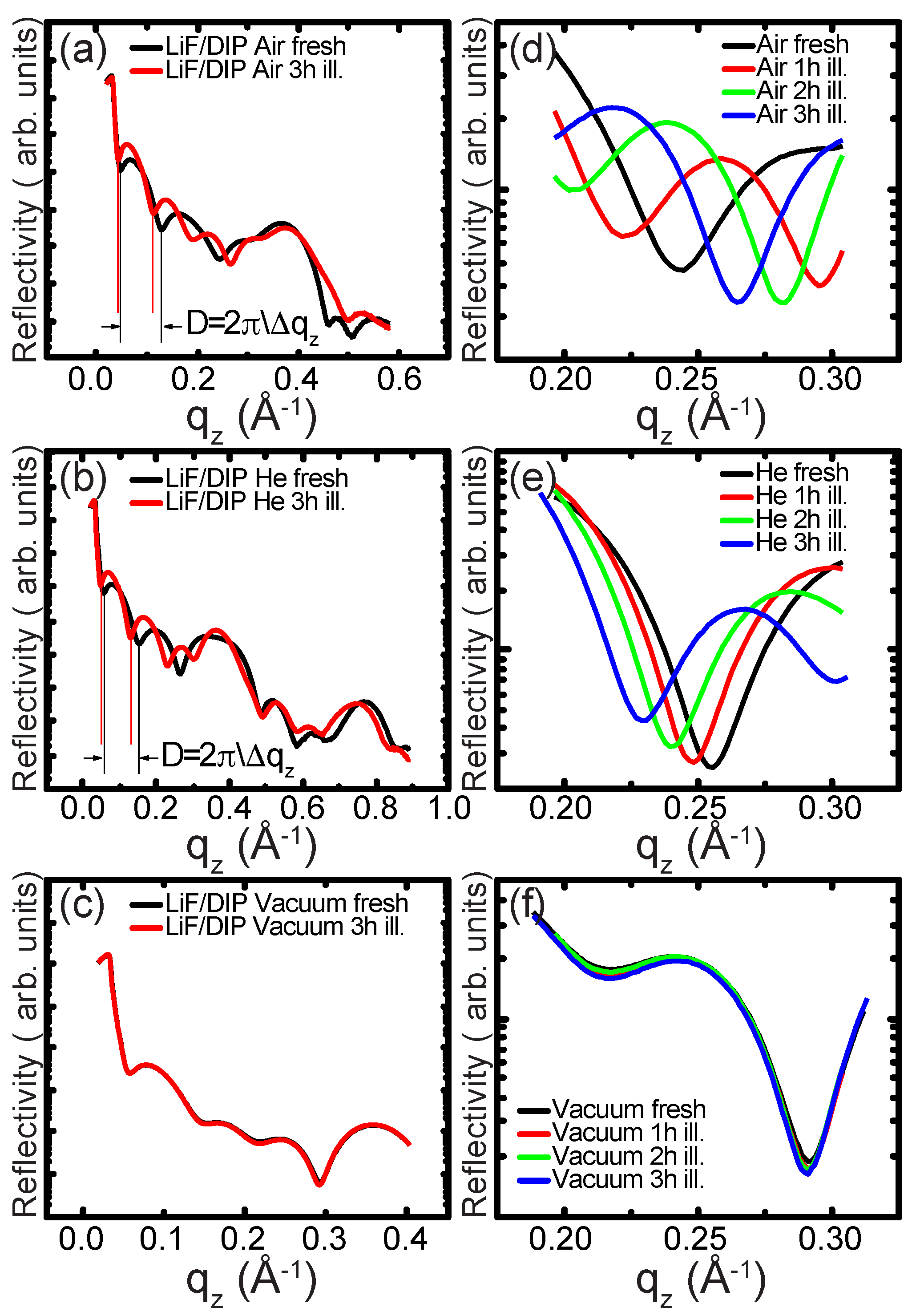
Figure 2 shows the reflectivity data obtained from three different LiF/DIP bilayer systems in (a) air, (b) helium, and (c) a vacuum under various radiation doses. Observations of the specular out-of-plane response under strong X-ray beam illumination with defined exposure time were conducted. The samples were measured after beam illumination with different durations of up to 3 hr on the same spot. The radiation dose can be determined in units of J/cm2 [53]
where K is the pre-factor dependent on the critical angle of the incident radiation, is the photon flux, is the incident energy, A is the illuminated area given by the beam footprint and slit size, and t is the exposure time.
The dose delivered to the film is controlled by the exposure time, exposure area, incident photon rate, photon energy, and interference between transmitted and reflected beams inside the film. The beam footprint is , and thus the exposed area is . For these experiments, the incidence angle was held around 2°, resulting in an exposed area of 0.25 cm2. The photon rate was proportional to the slit area, and, for this beam line, a typical value was = 1 × 10 photons/s for the vacuum configuration.
The photon energy, , was 1.602 × 10 J. As the experiments were performed in a reflection condition, with incident angles close to the critical angle of the organic film [44,54], the incident radiation was transmitted into the film and mostly reflected by the substrate. These transmitted and reflected waves can interfere, which leads to significant enhancement in the field intensity in the film. This interference effectively amplifies the dose; therefore, the damage is initiated at much shorter times, requiring a pre-factor of 5.5 [53]. From Equation (3), the samples were exposed to radiation doses of between 16 and 67 J/cm2.
It can be seen in Figure 2 that stable reflectivity curves were only observed when the sample was under vacuum conditions. However, illumination under ambient or inside a helium environment showed significant changes in the reflectivity curves. Shifts in the Kiessig oscillations were visible under the helium and air environments with the signal change being more pronounced in air. The analysis from the positions of the first two oscillation minima suggests an increased bilayer thickness in both cases.
The differences in thickness for the as-prepared and illuminated samples were 12.04 Å in the air and 11.34 Å in the helium atmosphere under a radiation dose of ∼65 J/cm2 for 3 h illumination as calculated using Equation (3). The films of DIP alone did not show this behaviour under even extended illumination [44,54].
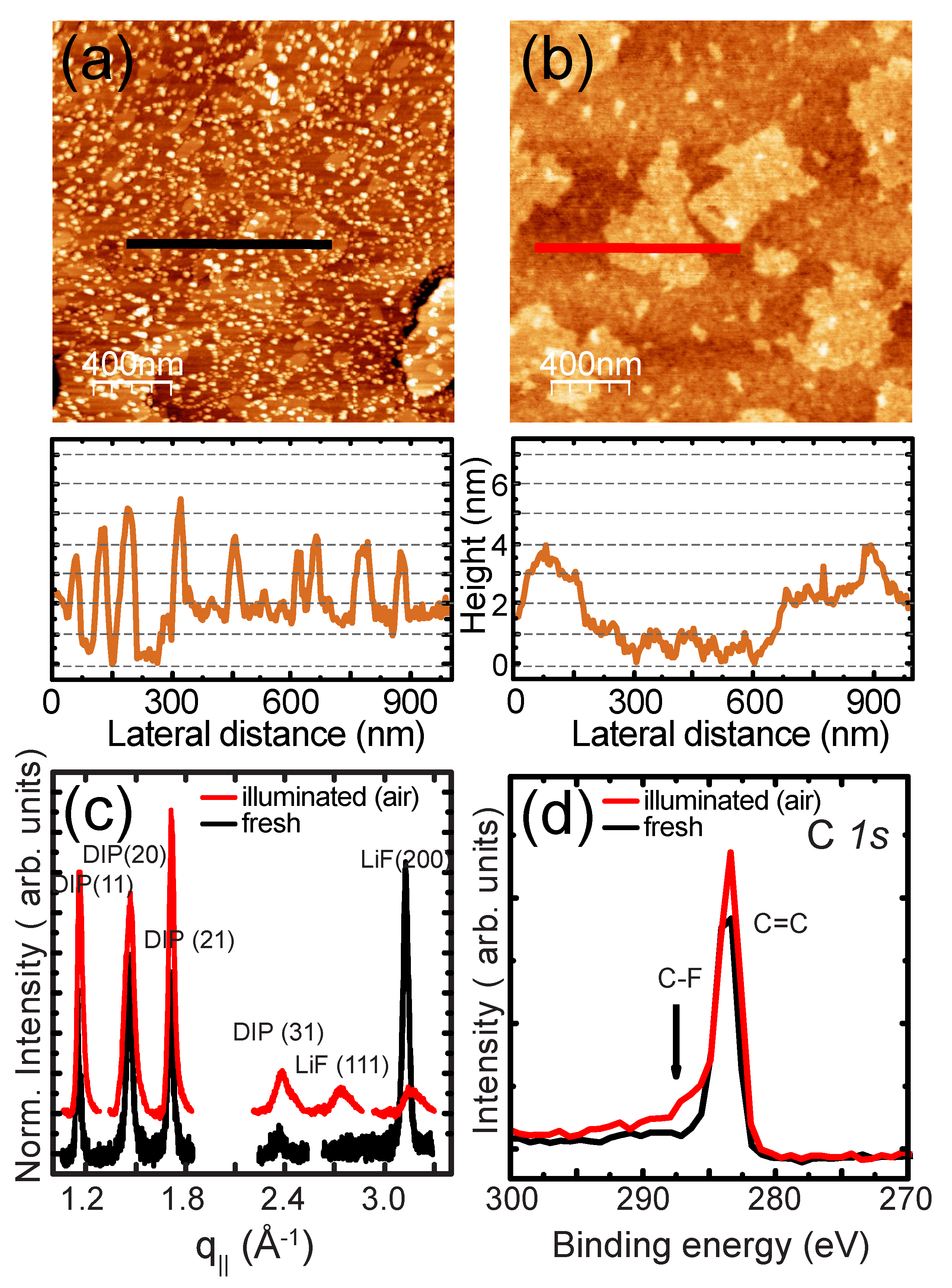
Topographical images before and after sample damage in Figure 3 indicated a drastic change in the surface morphology. Though it was not possible to confirm if the damaged spot caused by beam illumination was imaged exactly during the AFM measurements, the illuminated area was larger than the portion imaged under AFM, and this behaviour is representative of multiple spots on the sample surface. A significant loss of LiF islands and decreasing LiF island heights, as well as increasing noise in areas without visible LiF islands can be seen.
In parallel, increased lateral dimensions of the remaining particles was indicated. This suggests that the LiF nanoparticles either coalesced or evaporated completely. Simultaneously, the DIP islands were no longer large smooth plateaus, instead showing significant roughening. The height steps of the organic islands were slightly larger in the damaged sample topography, in keeping with the X-ray data. In-plane, there was little change in the DIP features; however, the relative intensities of the (20), (11), and (21) were slightly changed, suggesting that different crystallites were probed.
Interestingly, the LiF appeared to have changed in texture, with the emergence of a peak consistent with the (111) planes in LiF and attenuation of the (200) peak. The observed change in the LiF crystal texture was not consistent with that observed under other irradiation conditions [55] and, thus, warrants further study. The photoemission spectra of the damaged sample showed that the C 1s feature from DIP was intact, with only a slight shoulder at a higher binding energy, which may be consistent with bonding [56], but this is inconclusive.
As carbon signals from the molecule are difficult to deconvolute from adventious carbon [57], and there are no other features in the spectrum, it is common to study DIP during in-situ deposition in high vacuum conditions [45,58,59]. With the radiation-damaged samples, the presence of adventitous carbon makes an unambiguous determination of the impact on the DIP molecular structure nearly impossible.
To eliminate the possibility of heating-induced changes, accelerated aging experiments were performed. Stepwise heating in ambient conditions with controlled humidity of around 60% was performed on split samples. The samples consisted of a DIP film of around four ML deposited on a /Si(100) substrate at room temperature and an additional ultrathin LiF film that was deposited on one half of the sample.
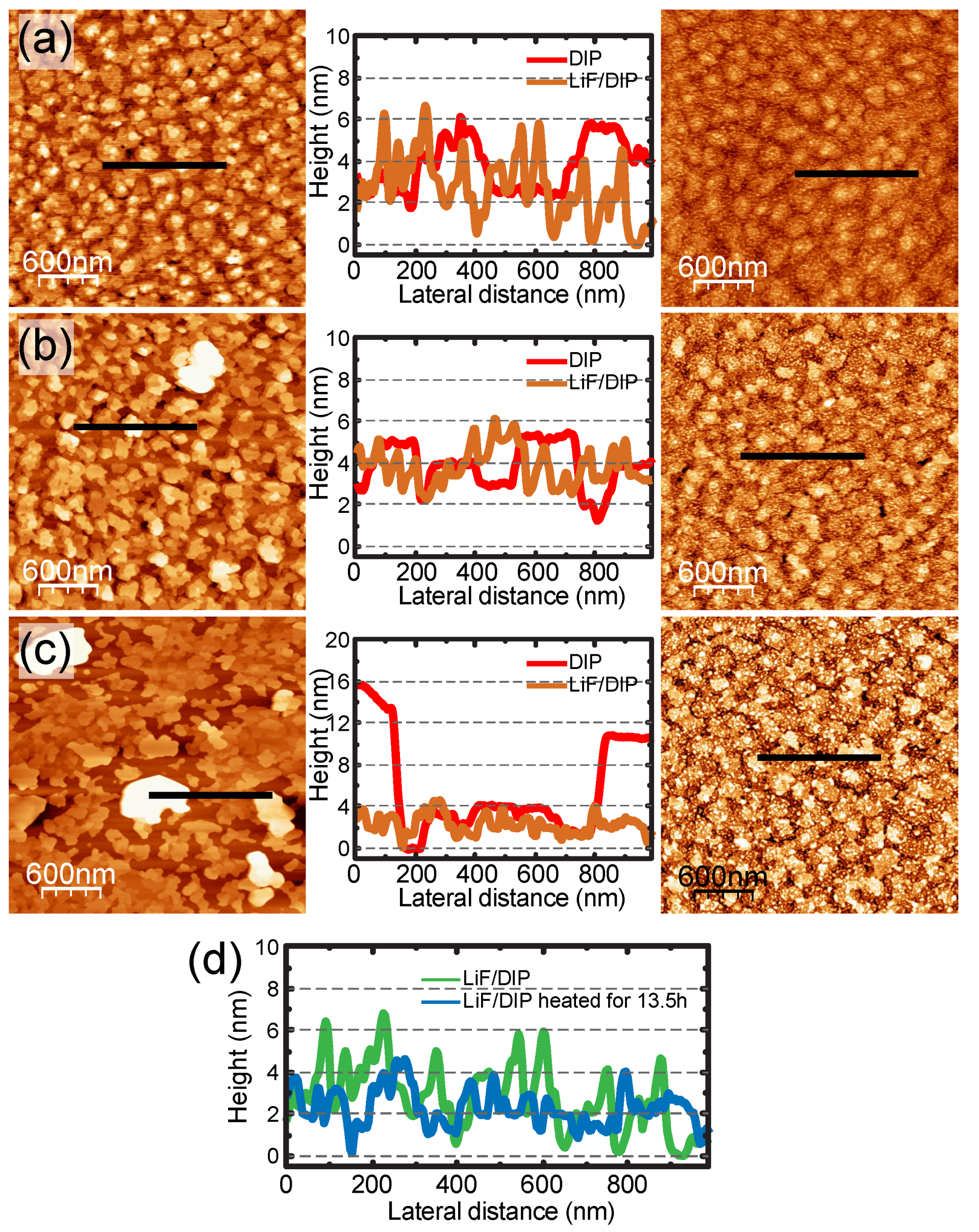
Figure 4 shows the morphology of the organic and bilayer surfaces in a series of heating steps at 9 h between (a) and (b) and 13.5 h between (a) and (c) (i.e., further heating for 4 h) at a temperature of 90 °C. The initial organic surfaces are similar on both areas of the substrate with lateral organic islands dimensions of around 150 nm. The LiF coverage was indeterminate because the DIP surface had a non-uniform height distribution as expected for room temperature deposition [44]. LiF formed randomly arranged islands on the organic surface. The heights of the LiF islands were again measured in the range of 40–60 Å for the initial conditions.
The morphology of the LiF-covered DIP film was essentially unchanged under heating. Lateral changes of DIP as well as crack formation were not observed. A small decrease of approximately 20 Å in the LiF island heights was observed after the first heating step. This difference remained almost constant even with further heating.
It is likely that the LiF particles penetrated into the organic film, as this temperature is sufficient to allow diffusion of the DIP molecules, as shown by the changing morphology of the organic layer on its own (the left-hand side Figure 4). The observed height difference is consistent with the measured layer thickness for the organic molecules as determined by X-ray diffraction, suggesting a constant penetration depth of one organic monolayer.
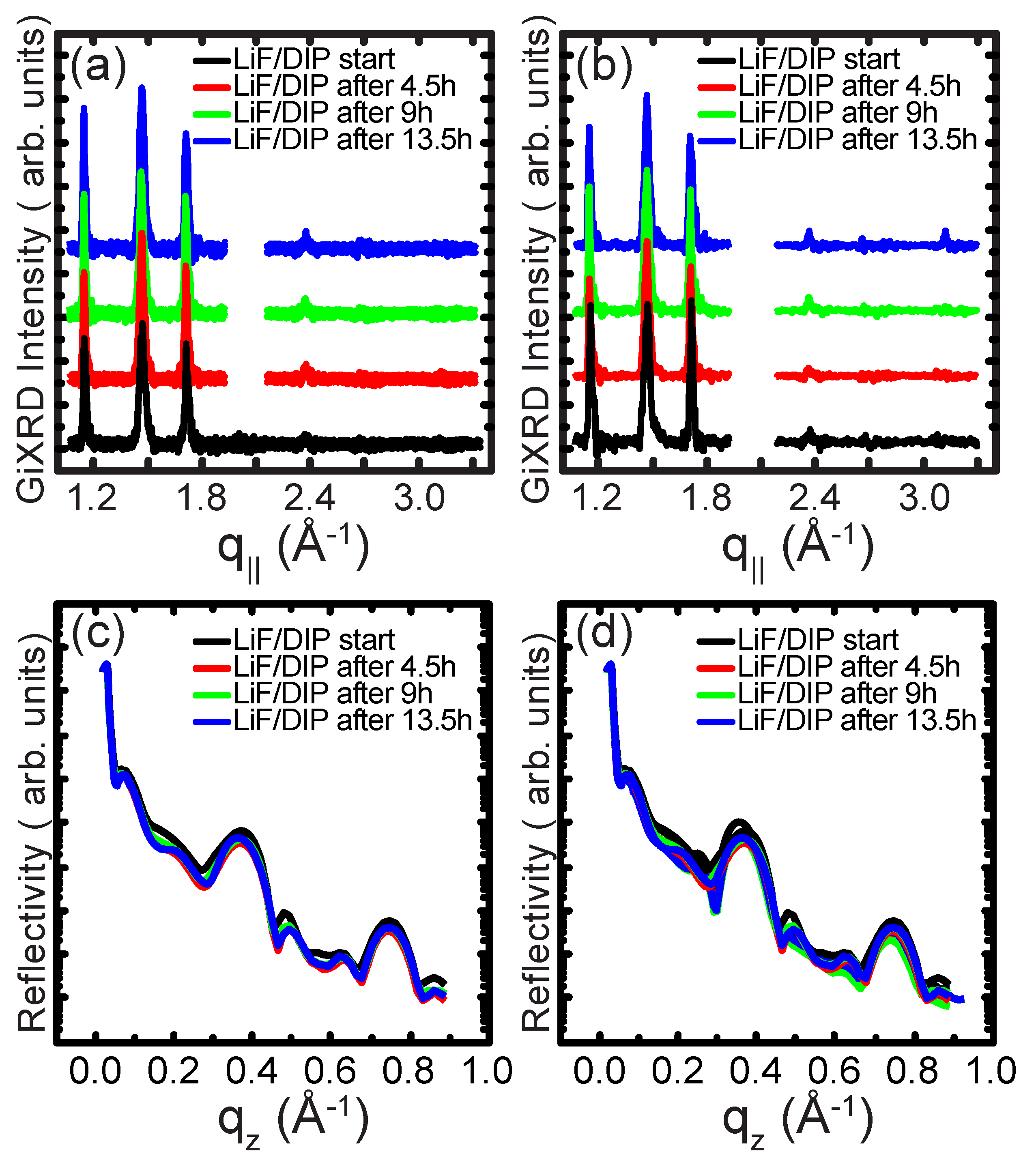
Similarly, the XRD studies in a vacuum in Figure 5 show only minimal changes of the Kiessig oscillations in the specular data, suggesting that the averaged total film thickness was kept constant. This was slightly more pronounced for the bare DIP, in keeping with the changes observed in the topography. Bragg signals from the multilayer stack also did not change significantly, which suggests that the layer-by-layer arrangement persisted. Although deposition at high substrate temperatures has been shown to convert polycrystalline LiF films to fully oriented single crystals [60,61], evolution of the (111) peaks was not observed in these films.
4. Discussion
LiF/DIP bilayer systems are unstable under high energy radiation when measured in ambient conditions or under a helium atmosphere. A transition of the specular out-of-plane response in these environments was observed. Shifts of the Kiessig oscillations caused by a variation of the bilayer thickness suggest the formation of additional layers with the same thickness in both atmospheres. Sharp and acute LiF islands that were present in the initial morphology vanished after the radiation influence.
The grazing incidence diffraction showed significantly attenuated signals from the nanoparticles, which suggests that the LiF crystallites became less textured, with the emergence of a (111) peak, similar to that observed for bulk films [36,37]. The desorption of the LiF particles as well as a lateral coalescence of the remaining particles appeared to occur. Damage to the underlying DIP layer was observed as a change in the local morphology, as well as in the possible formation of species.
The total thickness, as determined by reflectivity, increased, which is consistent with the observed behaviour of radiation-degraded polymers [53,62]. This is explained by the formation of layers with a more uniform electron density distribution. Localized heating is likely not a major mechanism for the observed changes, suggesting a photochemical mechanism due to the formation of reactive species.
Molecules consisting exclusively of aromatic hydrocarbons, like DIP, are generally resistant to radiation damage due to the absence of elements with high electron affinity [63]. The molecular structures formed by aromatic hydrocarbon rings will dissipate the incorporated radiation energy to the rings, and these molecules should be less affected by X-ray illumination compared with polymer systems under a similar radiation dose [53,62].
In addition, DIP crystallizes in a well-known structure [44,46,47], arranging in a rather densely packed crystalline structure, which should increase its resistance to X-ray damage. The enhanced destruction, therefore, is clearly related to the formation of a bi-layer structure. However, Dürr et al. [54] did not observe similar interfacial instability with a continuous Au film layer deposited on the surface of DIP.
Hence, it appears that the enhanced instability is a result of a submonolayer film of LiF nanoparticles. Nanoparticles have been shown to increase the effectiveness of X-ray treatments against drug-resistant bacterial infections [11] and cancer tumors [10,13,14,15].
Using nanoparticle materials with large X-ray absorption cross sections delivered to tumors results in much greater destruction compared with radiation alone [9], generating a high number of photoelectrons and free radicals as well as heating, which can lead to significant damage to organic structures [64]. This is typically achieved using high atomic number elements, such as Au, Fe, Gd, Hf, or I [9,10], as the cross-section is proportional to the atomic number.
Although LiF consists of low atomic weight elements, it is highly susceptible to irradiation, producing long lived electronically active defect centres, from a variety of sources across the energy spectrum, from 20 eV EUV irradiation [21] to high energy ions up to 21 MeV [27].
Even short exposures are typically sufficient to cause defects [21,30]. These defect centres, generally related to the formation of excited fluorine states (ions, Frenkel pairs, and ionized aggregates) [21,30], can be highly reactive [7] and mobile [23]. Additionally, they are emissive, generating secondary photons [7,21,25], which could be another source of degradation on the surrounding organic matter [10].
However, the formation of large numbers of defects usually requires doses three orders of magnitude higher than those observed in this study, in the kJ/cm2 range. Thermally evaporated thin films of LiF are known to be more sensitive to radiation damage compared with the bulk crystals [18]. Such films are known to consist of nanoparticles that coalesce into larger crystals above a critical thickness [33,34]. Due to the small size of the LiF nanoparticles on the DIP film, and their incomplete coverage on the DIP surface, it is likely that this prolonged exposure, even with a relatively small dose of energy, was sufficient to radically alter the LiF particles, generating fluorine in excited states or secondary photons that can affect the underlying DIP film.
Entani et al. [28] used high energy ions to dope graphene with fluorine from a deposited LiF overlayer, resulting from electronic excitation which possibly involves local bond breaking and recombination. Though the in-plane crystal structure of the DIP is unchanged with radiation damage, as seen by the GiXRD in Figure 3c, PES measurements of the bilayer system after irradiation suggest that some bonding may be occurring; however, the results are not conclusive (Figure 3d).
This effect is a photochemical reaction, requiring the presence of ions, as the damage does not appear in vacuum condition. As LiF is hygroscopic, it is possible that water contamination in both non-vacuum conditions was a source of reactive species that can modify the DIP layer, in addition to the reactive defect states or photons from the nanoparticles.
Though this effect was observed with keV radiation, one of the current challenges in radio therapy is to find materials that are effective in the MeV range [9,64]. As LiF is susceptible to radiation damage from multiple sources across the energy spectrum, including in the MeV range [27,28], this could represent a new avenue for using LiF or similar optically active materials that form colour centres and defects under irradiation to enhance the X-ray degradation of organic structures.
Author Contributions
Conceptualization, A.T.; methodology, F.M. and A.T.; formal analysis, F.M.; investigation, F.M.; resources, A.T.; data curation, A.T.; writing—original draft preparation, F.M.; writing—review and editing, A.T.; visualization, F.M.; supervision, A.T.; project administration, A.T.; funding acquisition, A.T. All authors have read and agreed to the published version of the manuscript.
Funding
This research was funded by a Marie Curie International Incoming Fellowship (LiFOrgPV 221165) and a European Reintegration Grant (NIOS 276963) within the 7th European Community Framework Programme.
Institutional Review Board Statement
Not applicable.
Informed Consent Statement
Not applicable.
Data Availability Statement
The data presented in this study are available in the supplementary information.
Acknowledgments
The authors would like to acknowledge the support of R. Weigel and A. Vlad at the MPI beamline at ANKA for diffraction measurements, S. Hirschmann at the Universität Stuttgart for DIP synthesis and purification, and H. Dosch and M. Ruhle at MPI-MF for access to equipment and support.
Conflicts of Interest
The authors declare no conflict of interest.
References
- Juers, D.H.; Weik, M. Similarities and Differences in Radiation Damage at 100 K versus 160 K in a Crystal of Thermolysin. J. Synchrotron Rad. 2011, 18, 329–337. [Google Scholar] [CrossRef]
- Reisz, J.A.; Bansal, N.; Qian, J.; Zhao, W.; Furdui, C.M. Effects of Ionizing Radiation on Biological Molecules—Mechanisms of Damage and Emerging Methods of Detection. Antioxid. Redox Signal. 2014, 21, 260–292. [Google Scholar] [CrossRef] [PubMed]
- Leermakers, P.A.; Vesley, G.F. Organic Photochemistry and the Excited State. J. Chem. Educ. 1964, 41, 535. [Google Scholar] [CrossRef]
- Faber, C.; Boulanger, P.; Attaccalite, C.; Duchemin, I.; Blase, X. Excited States Properties of Organic Molecules: From Density Functional Theory to the GW and Bethe–Salpeter Green’s Function Formalisms. Philos. Trans. R. Soc. A Math. Phys. Eng. Sci. 2014, 372, 20130271. [Google Scholar] [CrossRef] [Green Version]
- Michl, J.; Klessinger, M. Excited States and Photo-Chemistry of Organic Molecules, 1st ed.; Wiley-VCH: New York, NY, USA, 1995. [Google Scholar]
- Smith, H.I.; Schattenburg, M.L. X-ray Lithography from 500 to 30 Nm: X-ray Nanolithography. IBM J. Res. Dev. 1993, 37, 319–329. [Google Scholar] [CrossRef]
- Bonfigli, F.; Faenov, A.Y.; Flora, F.; Marolo, T.; Montereali, R.M.; Nichelatti, E.; Pikuz, T.A.; Reale, L.; Baldacchini, G. Point Defects in Lithium Fluoride Films for Micro-Radiography, X-ray Microscopy and Photonic Applications. Phys. Status Solidi A 2005, 202, 250–255. [Google Scholar] [CrossRef]
- Gillaspy, J.D.; Pomeroy, J.M.; Perrella, A.C.; Grube, H. The Potential of Highly Charged Ions: Possible Future Applications. J. Phys. Conf. Ser. 2007, 58, 104. [Google Scholar] [CrossRef]
- Schuemann, J.; Bagley, A.F.; Berbeco, R.; Bromma, K.; Butterworth, K.T.; Byrne, H.L.; Chithrani, B.D.; Cho, S.H.; Cook, J.R.; Favaudon, V.; et al. Roadmap for Metal Nanoparticles in Radiation Therapy: Current Status, Translational Challenges, and Future Directions. Phys. Med. Biol. 2020, 65, 21RM02. [Google Scholar] [CrossRef] [PubMed]
- Kuncic, Z.; Lacombe, S. Nanoparticle Radio-Enhancement: Principles, Progress and Application to Cancer Treatment. Phys. Med. Biol. 2018, 63, 02TR01. [Google Scholar] [CrossRef]
- Luo, Y.; Hossain, M.; Wang, C.; Qiao, Y.; An, J.; Ma, L.; Su, M. Targeted Nanoparticles for Enhanced X-ray Radiation Killing of Multidrug-Resistant Bacteria. Nanoscale 2012, 5, 687–694. [Google Scholar] [CrossRef]
- McMahon, S.J.; Mendenhall, M.H.; Jain, S.; Currell, F. Radiotherapy in the Presence of Contrast Agents: A General Figure of Merit and Its Application to Gold Nanoparticles. Phys. Med. Biol. 2008, 53, 5635. [Google Scholar] [CrossRef]
- Nakayama, M.; Sasaki, R.; Ogino, C.; Tanaka, T.; Morita, K.; Umetsu, M.; Ohara, S.; Tan, Z.; Nishimura, Y.; Akasaka, H.; et al. Titanium Peroxide Nanoparticles Enhanced Cytotoxic Effects of X-ray Irradiation against Pancreatic Cancer Model through Reactive Oxygen Species Generation in Vitro and in Vivo. Radiat. Oncol. 2016, 11, 91. [Google Scholar] [CrossRef] [PubMed] [Green Version]
- Teraoka, S.; Kakei, Y.; Akashi, M.; Iwata, E.; Hasegawa, T.; Miyawaki, D.; Sasaki, R.; Komori, T. Gold Nanoparticles Enhance X-ray Irradiation-Induced Apoptosis in Head and Neck Squamous Cell Carcinoma in Vitro. Biomed. Rep. 2018, 9, 415–420. [Google Scholar] [CrossRef] [Green Version]
- Zhang, F.; Liu, S.; Zhang, N.; Kuang, Y.; Li, W.; Gai, S.; He, F.; Gulzar, A.; Yang, P. X-ray-Triggered NO-Released Bi–SNO Nanoparticles: All-in-One Nano-Radiosensitizer with Photothermal/Gas Therapy for Enhanced Radiotherapy. Nanoscale 2020, 12, 19293–19307. [Google Scholar] [CrossRef] [PubMed]
- Baldacchini, G.; Goncharova, O.; Kalinov, V.S.; Montereali, R.M.; Nichelatti, E.; Vincenti, A.; Voitovich, A.P. Optical Properties of Coloured LiF Crystals with given Content of Oxygen, Hydroxyl and Metal Impurities. Phys. Status Solidi C 2007, 4, 744–748. [Google Scholar] [CrossRef]
- Montereali, R.M.; Almaviva, S.; Bonfigli, F.; Cricenti, A.; Faenov, A.; Flora, F.; Gaudio, P.; Lai, A.; Martellucci, S.; Nichelatti, E.; et al. Lithium Fluoride Thin-Film Detectors for Soft X-ray Imaging at High Spatial Resolution. Nuc. Instr. Meth. Phys. Res. A Accel. Spectro. Detect. Assoc. Equip. 2010, 623, 758–762. [Google Scholar] [CrossRef]
- Baldacchini, G.; Bollanti, S.; Bonfigli, F.; Flora, F.; Di Lazzaro, P.; Lai, A.; Marolo, T.; Montereali, R.M.; Murra, D. Soft X-ray Submicron Imaging Detector Based on Point Defects in LiF. Rev. Sci. Instruments 2005, 76, 113104. [Google Scholar] [CrossRef]
- Cosset, F.; Celerier, A.; Barelaud, B.; Vareille, J.C. Thin Reactive LiF Films for Nuclear Sensors. Thin Solid Films 1997, 303, 191–195. [Google Scholar] [CrossRef]
- Pedersen, K.; Andersen, T.D.; Rødal, J.; Olsen, D.R. Sensitivity and Stability of LiF Thermoluminescence Dosimeters. Med. Dosim. 1995, 20, 263–267. [Google Scholar] [CrossRef]
- Flora, F.; Baldacchini, G.; Bonfigli, F.; Lai, A.; Marolo, T.; Mezi, L.; Montereali, R.M.; Murra, D.; Lisi, N.; Nichelatti, E.; et al. Lithium Fluoride Coloration by Laser-Plasma Soft X-rays: A Promising Tool for X-ray Microscopy and Photonics. In Laser-Generated and Other Laboratory X-ray and EUV Sources, Optics, and Applications; International Society for Optics and Photonics (SPIE): Bellingham, WA, USA, 2004; Volume 5196, pp. 298–310. [Google Scholar] [CrossRef]
- Van den Bosch, A. γ-Radiolysis of LiF. Radiat. Eff. 1973, 19, 129–133. [Google Scholar] [CrossRef]
- Kubo, K. Radiation Effects in LiF Crystals. J. Phys. Soc. Jpn. 1961, 16, 2294–2306. [Google Scholar] [CrossRef]
- Baldacchini, G.; Montereali, R.M.; Scacco, A.; Cremona, M.; D’Auria, G. Point Defects Induced in LiF by Low Energy Electrons; Technical Report; Ente per le Nuove Technologie, L’Energia e L’Ambiente (ENEA): Rome, Italy, 1997. [Google Scholar]
- Montereali, R.M.; Bonfigli, F.; Menchini, F.; Vincenti, M.A. Optical Spectroscopy and Microscopy of Radiation-Induced Light-Emitting Point Defects in Lithium Fluoride Crystals and Films. Low Temp. Phys. 2012, 38, 779. [Google Scholar] [CrossRef] [Green Version]
- Golek, F.; Sobolewski, W.J. Electron Beam Induced Alteration of LiF Thin Films Monitored by EELS. Solid State Commun. 1999, 110, 143–146. [Google Scholar] [CrossRef]
- Zabels, R.; Manika, I.; Schwartz, K.; Maniks, J.; Dauletbekova, A.; Grants, R.; Baizhumanov, M.; Zdorovets, M. Formation of Dislocations and Hardening of LiF under High-Dose Irradiation with 5–21 MeV 12C Ions. Appl. Phys. A 2017, 123, 320. [Google Scholar] [CrossRef]
- Entani, S.; Mizuguchi, M.; Watanabe, H.; Antipina, L.Y.; Sorokin, P.; Avramov, P.V.; Naramoto, H.; Sakai, S. Effective Fluorination of Single-Layer Graphene by High-Energy Ion Irradiation through a LiF Overlayer. RSC Adv. 2016, 6, 68525–68529. [Google Scholar] [CrossRef]
- Somma, F.; Montereali, R.; Vincenti, M.; Polosan, S.; Secu, M. Radiation Induced Defects in Pb2+-Doped LiF Crystals. Phys. Procedia 2009, 2, 211–221. [Google Scholar] [CrossRef] [Green Version]
- Schwartz, C.P.; Ponce, F.; Friedrich, S.; Cramer, S.P.; Vinson, J.; Prendergast, D. Temperature and Radiation Effects at the Fluorine K-Edge in LiF. J. Electron Spectrosc. Relat. Phenom. 2017, 218, 30–34. [Google Scholar] [CrossRef] [Green Version]
- Nadeau, J.S.; Johnston, W.G. Hardening of Lithium Fluoride Crystals by Irradiation. J. Appl. Phys. 1961, 32, 2563–2565. [Google Scholar] [CrossRef]
- Pomeroy, R. The Reactivity of Fluorine. Chem. Educ. 2015, 20, 260–264. [Google Scholar]
- Lee, S.I.; Liang, K.; Hui, L.S.; Arbi, R.; Munir, M.; Lee, S.J.; Kim, J.W.; Kim, K.J.; Kim, W.Y.; Turak, A. Necessity of Submonolayer LiF Anode Interlayers for Improved Device Performance in Blue Phosphorescent OLEDs. J. Mater. Sci. Mater. Electron. 2021, 32, 1161–1177. [Google Scholar] [CrossRef]
- Maye, F. Morphological and Structural Study of Ultrathin Lithium Floride Films on Organic Molecule Surfaces. Ph.D. Thesis, University of Stuttgart, Stuttgart, Germany, 2011. [Google Scholar]
- Gołek, F.; Mazur, P. LiF Thin Layers on Si(100) Studied by ESD, LEED, AES, and AFM. Surf. Sci. 2003, 541, 173–181. [Google Scholar] [CrossRef]
- Montereali, R.M.; Baldacchini, G.; Martelli, S.; Do Carmo, L.S. LiF Films: Production and Characterization. Thin Solid Films 1991, 196, 75–83. [Google Scholar] [CrossRef]
- Di Nunzio, P.E.; Fornarini, L.; Martelli, S.; Montereali, R.M. Texture Analysis of LiF Thin Films Evaporated onto Amorphous Substrates at Different Temperatures. Phys. Status Solidi Appl. Res. 1997, 164, 747–756. [Google Scholar] [CrossRef]
- Stierle, A.; Steinhauser, A.; Ruhm, A.; Renner, F.U.; Weigel, R.; Kasper, N.; Dosch, H. Dedicated Max-Planck Beamline for the in Situ Investigation of Interfaces and Thin Films. Rev. Sci. Instrum. 2004, 75, 5302–5307. [Google Scholar] [CrossRef]
- Delheusy, M.; Major, J.; Rühm, A.; Stierle, A. Dedicated Beamlines for In-Situ Investigations of Materials in Reduced Dimensions. Int. J. Mater. Res. 2011, 102, 913–924. [Google Scholar] [CrossRef]
- Nannarone, S.; Borgatti, F.; DeLuisa, A.; Doyle, B.P.; Gazzadi, G.C.; Giglia, A.; Finetti, P.; Mahne, N.; Pasquali, L.; Pedio, M.; et al. The BEAR Beamline at Elettra. In Proceedings of the AIP Conference Proceedings, Sacramento, CA, USA, 4–5 August 2004; Volume 705, pp. 450–453. [Google Scholar] [CrossRef]
- Horcas, I.; Fernández, R.; Gómez-Rodríguez, J.M.; Colchero, J.; Gómez-Herrero, J.; Baro, A.M. WSXM: A Software for Scanning Probe Microscopy and a Tool for Nanotechnology. Rev. Sci. Instrum. 2007, 78, 013705. [Google Scholar] [CrossRef]
- Heidkamp, J.; Maye, F.; Turak, A.Z. Stabilization Methods for Small Molecule Dewetting on Indium Tin Oxide Substrates for Organic Photovoltaics. Procceedings of Photonics North 2013, Ottawa, ON, Canada, 3–5 June 2013; Cheben, P., Schmid, J., Boudoux, C., Chen, L.R., Delâge, A., Janz, S., Kashyap, R., Lockwood, D.J., Loock, H.P., Mi, Z., Eds.; SPIE: Ottawa, ON, Canada, 2013; Volume 8915, p. 891508. [Google Scholar] [CrossRef]
- Heinemeyer, U.; Scholz, R.; Gisslén, L.; Alonso, M.I.; Ossó, J.O.; Garriga, M.; Hinderhofer, A.; Kytka, M.; Kowarik, S.; Gerlach, A.; et al. Exciton-Phonon Coupling in Diindenoperylene Thin Films. Phys. Rev. B 2008, 78. [Google Scholar] [CrossRef] [Green Version]
- Turak, A.; Nguyen, M.; Maye, F.; Heidkamp, J.; Lienerth, P.; Wrachtrup, J.; Dosch, H. Nanoscale Engineering of Exciton Dissociating Interfaces in Organic Photovoltaics. J. Nano Res. 2011, 14, 125–136. [Google Scholar] [CrossRef]
- Huang, Y.L.; Chen, W.; Huang, H.; Qi, D.C.; Chen, S.; Gao, X.Y.; Pflaum, J.; Wee, A.T.S. Ultrathin Films of Diindenoperylene on Graphite and SiO2. J. Phys. Chem. C 2009, 113, 9251–9255. [Google Scholar] [CrossRef]
- Dürr, A.C.; Schreiber, F.; Münch, M.; Karl, N.; Krause, B.; Kruppa, V.; Dosch, H. High Structural Order in Thin Films of the Organic Semiconductor Diindenoperylene. Appl. Phys. Lett. 2002, 81, 2276–2278. [Google Scholar] [CrossRef] [Green Version]
- Dürr, A.; Nickel, B.; Sharma, V.; Täffner, U.; Dosch, H. Observation of Competing Modes in the Growth of Diindenoperylene on SiO2. Thin Solid Films 2006, 503, 127–132. [Google Scholar] [CrossRef]
- Zhang, X.N.; Barrena, E.; de Oteyza, D.G.; Dosch, H. Transition from Layer-by-Layer to Rapid Roughening in the Growth of DIP on SiO2. Surf. Sci. 2007, 601, 2420–2425. [Google Scholar] [CrossRef]
- Dürr, A.C.; Schreiber, F.; Ritley, K.A.; Kruppa, V.; Krug, J.; Dosch, H.; Struth, B. Rapid Roughening in Thin Film Growth of an Organic Semiconductor (Diindenoperylene). Phys. Rev. Lett. 2003, 90, 16104. [Google Scholar] [CrossRef] [PubMed] [Green Version]
- Kiessig, H. Untersuchungen Zur Totalreflexion von Röntgenstrahlen. Ann. Phys. 1931, 402, 715–768. [Google Scholar] [CrossRef]
- Münch, M. Strukturelle Beeinflussung der Elektrischen Transporteigenschaften dünner Organischer Schichten. Ph.D. Thesis, University of Stuttgart, Stuttgart, Germany, 2001. [Google Scholar]
- Dosch, H.; Batterman, B.W.; Wack, D.C. Depth-Controlled Grazing-Incidence Diffraction of Synchrotron X Radiation. Phys. Rev. Lett. 1986, 56, 1144–1147. [Google Scholar] [CrossRef] [PubMed]
- Vaselabadi, S.A.; Shakarisaz, D.; Ruchhoeft, P.; Strzalka, J.; Stein, G.E. Radiation Damage in Polymer Films from Grazing-Incidence X-ray Scattering Measurements. J. Polym. Sci. Part B Polym. Phys. 2016, 54, 1074–1086. [Google Scholar] [CrossRef]
- Dürr, A.C.; Koch, N.; Kelsch, M.; Rühm, A.; Ghijsen, J.; Johnson, R.; Pireaux, J.J.; Schwartz, J.; Schreiber, F.; Dosch, H.; et al. Interplay between Morphology, Structure, and Electronic Properties at Diindenoperylene-Gold Interfaces. Phys. Rev. B 2003, 68, 115428. [Google Scholar] [CrossRef] [Green Version]
- Goncharova, O.; Montereali, R.M.; Baldacchini, G. Thin-Film Structures with Nanocrystals: An Origin of Enhanced Photo-Response. J. Phys. Conf. Ser. 2010, 249, 012063. [Google Scholar] [CrossRef] [Green Version]
- Turak, A.; Zgierski, M.Z.; Dharma-Wardana, M.W.C. LiF Doping of C60 Studied with X-ray Photoemission Shake-Up Analysis. ECS J. Solid State Sci. Technol. 2017, 6, M3116–M3121. [Google Scholar] [CrossRef]
- Greczynski, G.; Hultman, L. C 1s Peak of Adventitious Carbon Aligns to the Vacuum Level: Dire Consequences for Material’s Bonding Assignment by Photoelectron Spectroscopy. ChemPhysChem 2017, 18, 1507–1512. [Google Scholar] [CrossRef]
- Casu, M.B. Growth, Structure, and Electronic Properties in Organic Thin Films Deposited on Metal Surfaces Investigated by Low Energy Electron Microscopy and Photoelectron Emission Microscopy. J. Electron Spectrosc. Relat. Phenom. 2015, 204, 39–48. [Google Scholar] [CrossRef]
- Schuster, B.E.; Casu, M.B.; Biswas, I.; Hinderhofer, A.; Gerlach, A.; Schreiber, F.; Chassé, T. Role of the Substrate in Electronic Structure, Molecular Orientation, and Morphology of Organic Thin Films: Diindenoperylene on Rutile TiO2(110). Phys. Chem. Chem. Phys. 2009, 11, 9000–9004. [Google Scholar] [CrossRef]
- Perea, A.; Gonzalo, J.; Afonso, C.N.; Martelli, S.; Montereali, R.M. On the Growth of LiF Films by Pulsed Laser Deposition. Appl. Surf. Sci. 1999, 138–139, 533–537. [Google Scholar] [CrossRef]
- Henley, S.; Ashfold, M.; Pearce, S. The Structure and Composition of Lithium Fluoride Films Grown by Off-Axis Pulsed Laser Ablation. Appl. Surf. Sci. 2003, 217, 68–77. [Google Scholar] [CrossRef]
- Neuhold, A.; Novák, J.; Flesch, H.G.; Moser, A.; Djuric, T.; Grodd, L.; Grigorian, S.; Pietsch, U.; Resel, R. X-ray Radiation Damage of Organic Semiconductor Thin Films during Grazing Incidence Diffraction Experiments. Nucl. Instruments Methods Phys. Res. Sect. B Beam Interact. Mater. Atoms 2012, 284, 64–68. [Google Scholar] [CrossRef]
- Chapiro, A. Chemical Modifications in Irradiated Polymers. Nucl. Instrum. Methods Phys. Res. Sect. B Beam Interact. Mater. At. 1988, 32, 111–114. [Google Scholar] [CrossRef]
- Her, S.; Jaffray, D.A.; Allen, C. Gold Nanoparticles for Applications in Cancer Radiotherapy: Mechanisms and Recent Advancements. Adv. Drug Deliv. Rev. 2017, 109, 84–101. [Google Scholar] [CrossRef] [PubMed]
Figure 1.
(a) AFM micrograph of the bilayer configuration LiF/DIP/SiO2 shows the submonolayer coverage of nanometer sized LiF islands. The large flat plateau islands of DIP can be observed. (b) The height profile corresponding to the line visible in (a) showing the height steps between different DIP monolayers and the peaked height fluctuations (20–60 Å) due to LiF. A defect site of the organic thin film is indicated showing the total thickness of the organic film (∼68 Å, up to four monolayers with 17.1 Å per monolayer) (c) X-ray reflectivity (“specular diffraction”) data from two samples, a single film of DIP/SiO2 and a LiF/DIP/SiO2 bilayer configuration, labelled with the pseudo-Bragg positions observed. (d) The grazing incidence X-ray diffraction data of single layer and bilayer films of DIP/SiO2, with observed features assigned to the DIP and LiF crystal lattice planes. Centre positions of the observed in-plane peaks were fitted with Lorentzian distribution functions. (e) Friction force micrographs of DIP, showing the regular arrangement of molecules within an island, with schematic representation of the molecular arrangement in-plane and out-of-plane in the observable crystallographic planes in real space for the DIP herringbone structure and LiF FCC structure. The measured monolayer thickness and expected tilt angle for DIP is also shown schematically.

Figure 2.
The X-ray reflectivity of three different LiF/DIP bilayer systems under (a) air, (b) helium, and (c) vacuum conditions before and after illumination. (d–f) Magnified view of the first Kiessig oscillation minima after 1, 2, and 3 h 10 keV X-ray illumination for each sample. Stable signals were only obtained under vacuum conditions.

Figure 3.
AFM micrographs of the surface morphology of the LiF/DIP bilayer configuration (a) before and (b) after radiation damage in air and helium atmospheres. The line profiles underneath correspond to the line shown in the AFM micrographs. (c) The grazing incidence X-ray diffraction data of pristine and irradiated bilayer films of LiF/DIP/ with observed features assigned to the DIP and LiF crystal lattice planes. The DIP structure is unchanged, whereas the LiF appears to become less textured, with an emerging feature assigned to the {111} planes. The data are normalized to the highest peak and offset to allow a comparison of the features.

Figure 4.
AFM micrographs of (a) the initial surfaces, (b) the surfaces after 9 h heating and (c) after 13.5 h heating at 90 °C of parallel-grown DIP (left) and LiF/DIP (right). The line profiles in the middle correspond to the lines in the AFM images. (d) Line profiles showing the comparison of LiF island heights before and after heating, corresponding to the lines indicated in the corresponding AFM images for the LiF/DIP bilayer.

Figure 5.
(a,b) In-plane and (c,d) specular XRD data of DIP (a,c) and LiF/DIP (b,d) split sample. The samples were heated for the labeled time at 90 °C.
Figure 5.
(a,b) In-plane and (c,d) specular XRD data of DIP (a,c) and LiF/DIP (b,d) split sample. The samples were heated for the labeled time at 90 °C.

Publisher’s Note: MDPI stays neutral with regard to jurisdictional claims in published maps and institutional affiliations. |
© 2021 by the authors. Licensee MDPI, Basel, Switzerland. This article is an open access article distributed under the terms and conditions of the Creative Commons Attribution (CC BY) license (https://creativecommons.org/licenses/by/4.0/).
Share and Cite
MDPI and ACS Style
Maye, F.; Turak, A. LiF Nanoparticles Enhance Targeted Degradation of Organic Material under Low Dose X-ray Irradiation. Radiation 2021, 1, 131-144. https://0-doi-org.brum.beds.ac.uk/10.3390/radiation1020012
AMA Style
Maye F, Turak A. LiF Nanoparticles Enhance Targeted Degradation of Organic Material under Low Dose X-ray Irradiation. Radiation. 2021; 1(2):131-144. https://0-doi-org.brum.beds.ac.uk/10.3390/radiation1020012
Chicago/Turabian StyleMaye, Felix, and Ayse Turak. 2021. "LiF Nanoparticles Enhance Targeted Degradation of Organic Material under Low Dose X-ray Irradiation" Radiation 1, no. 2: 131-144. https://0-doi-org.brum.beds.ac.uk/10.3390/radiation1020012