Communication

Influence of Cement Thickness on the Polymerization Shrinkage Stress of Adhesively Cemented Composite Inlays: Photoelastic and Finite Element Analysis

by
Larissa Mendes Campaner
*,
Alana Barbosa Alves Pinto
,
Amir Mohidin Demachkia
,
Tarcísio José de Arruda Paes-Junior
,
Clóvis Pagani
and
Alexandre Luiz Souto Borges
Institute of Science and Technology, São Paulo State University UNESP, São José dos Campos 12245-000, Brazil
*
Author to whom correspondence should be addressed.
Submission received: 12 May 2021 / Revised: 7 June 2021 / Accepted: 11 June 2021 / Published: 21 June 2021

Abstract

:
The objective of this study was to analyze the effect of cement thickness on the strain and stresses resulting from the polymerization of resin cement using photoelasticity and Finite Element Analysis (FEA). For this study, twenty upper first premolars with inlay cavity preparation were constructed from photoelastic resin and restored with composite resin inlay. The samples were divided into two groups (n = 10) according to the film thickness of resin cement material. For Group 1, the film thickness was 100 μm; for Group 2, the film thickness was 400 μm. After polymerization of the cement, photoelastic analysis and finite element analysis (FEA) were performed. In the photoelastic analysis, Group 2 showed higher strain with the presence of second-order fringe even after 24 h. In Group 1, the formation of first order fringes was not observed, even after 24 h. In the FEA analysis, the greatest cusp deflection and tensile stress occurred in Group 2 (0.00026 mm and 0.305 MPa, respectively) due to the polymerization shrinkage in the lingual cusp compared to Group 1 (0.000107 mm and 0.210 MPa, respectively). It can be concluded that the thickness of the resin cement influences the cusp deflection, with the greater thickness of the cement layer, the greater stresses and deformations in the tooth structure occur.

1. Introduction

The main functions of dental cement are to fix the restoration to the prepared tooth, and fill the space between them, in order to prevent microleakage [1]. The different physical and chemical properties of the luting agents will define whether the cement is temporary or permanent. An ideal luting agent should have characteristics of biocompatibility, long-term fluoride release, resistance to functional forces, low or no solubility and adsorption in water, be aesthetic, radiopaque, and have good adhesion [2]. Although no luting agent provides all the ideal characteristics, resin cements have been commonly used due to their high compressive strength, low solubility, high resistance, and low wear, in addition to aesthetics and good adhesion capacity [3].
Although composite resin materials have been successfully improved in the last years, polymerization shrinkage remained an unsolved problem [4] which is influenced by the composition of the organic matrix and the amount of filler [5,6]. Some studies have reported that a thin layer of adhesive cement has low polymerization shrinkage [7]. However, a thin layer of adhesive cement might have a high tensile stress, which is directly related to the stress developed at the bonding interface. Thereby, the shrinkage stress can be converted into linear tensile stress [8]. Excess cement can lead to biofilm adhesion at its interface, impacting the long-term survival of restorations [9].
Another factor for the success of the restoration is the proper curing of the resin cement, ensuring better mechanical properties and satisfactory performance. Inadequate polymerization is characterized by a low degree of chemical conversion, which can decrease physical properties and compromise the bond strength of the restoration to the tooth [10,11]. The degree of cement conversion depends on the type and thickness of the restorative material used. The increase in the degree of conversion over time may indicate a late polymerization, which affects the clinical performance of the restoration. The proper choice of cement according to the restorative material used will directly influence the lifetime of the restoration.
Photoelastic analysis is an experimental method widely used to analyze stress due to its relative simplicity and reliability in terms of clinical agreement of the findings [12]. The development of fully automated polariscopes allows full-field analysis of any of stress [13]. A photoelastic image is obtained during the photoelastic analysis using a standard camera and lens to visualize the photoelastic fringe patterns. Alternate fringes are formed, which order numbers depending on the intensity of the strain magnitude on the material. The isochromatic fringes represent regions where the difference between the principal strains is constant [14].
The finite element analysis (FEA) is another biomechanical tool used to analyze stress distribution. This analysis promotes is a static and linear study, but it is possible to obtain accurate results [15,16]. Many previous studies have measured polymerization shrinkage of composite resin by using photoelastic analysis [4,13,17] and finite element analysis (FEA) [18,19,20] to evaluate the theory of elasticity, the materials elasticity, and stress distribution.
Based on this, the purpose of this study was to analyze the biomechanical behavior resulting from the polymerization of resin cements using two different thicknesses (100 and 400 µm) by means of photoelastic and finite element analysis.
The null hypothesis was that there will be no difference in mechanical behavior in the polymerization of resin cements with two different thicknesses.

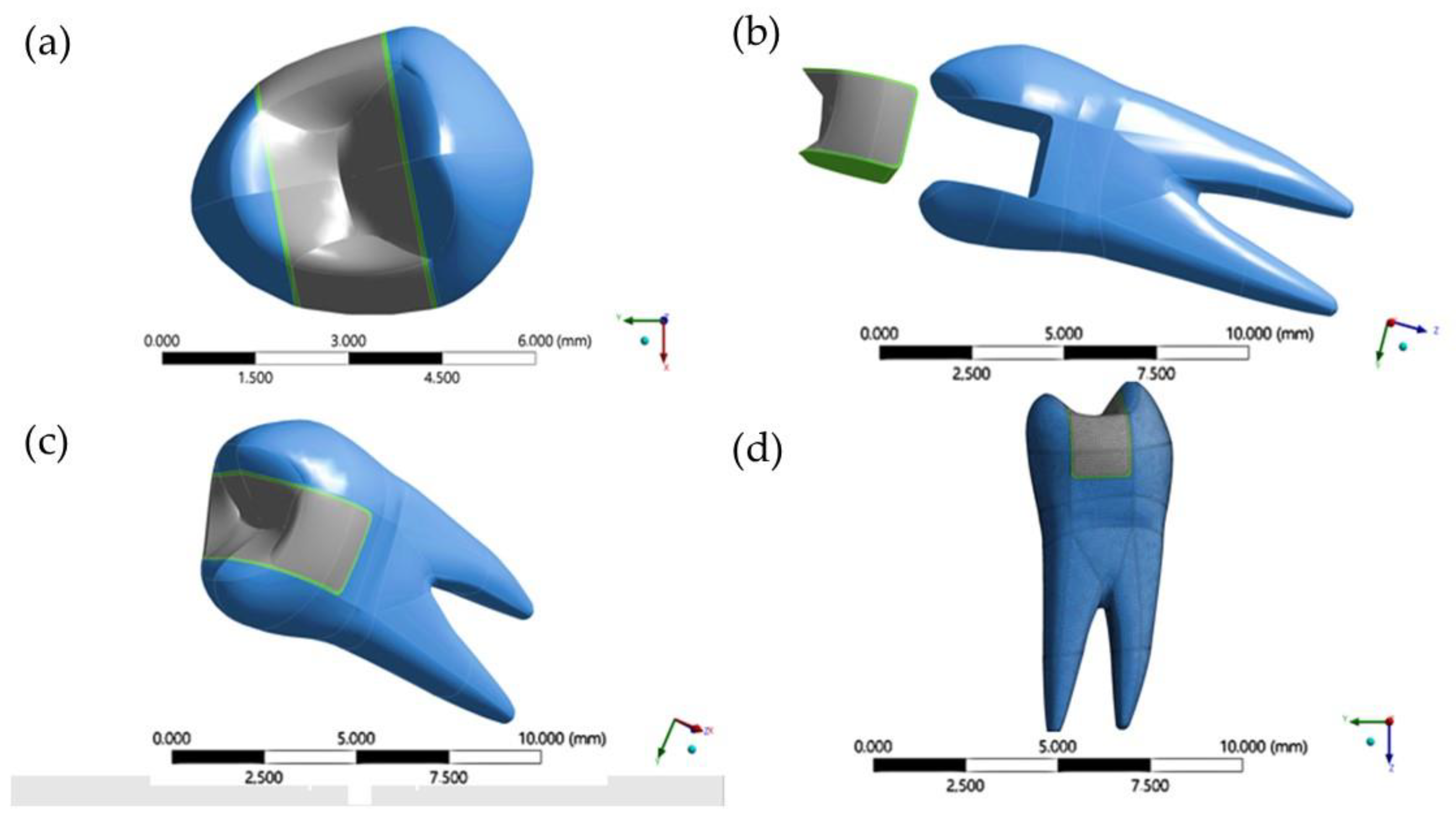
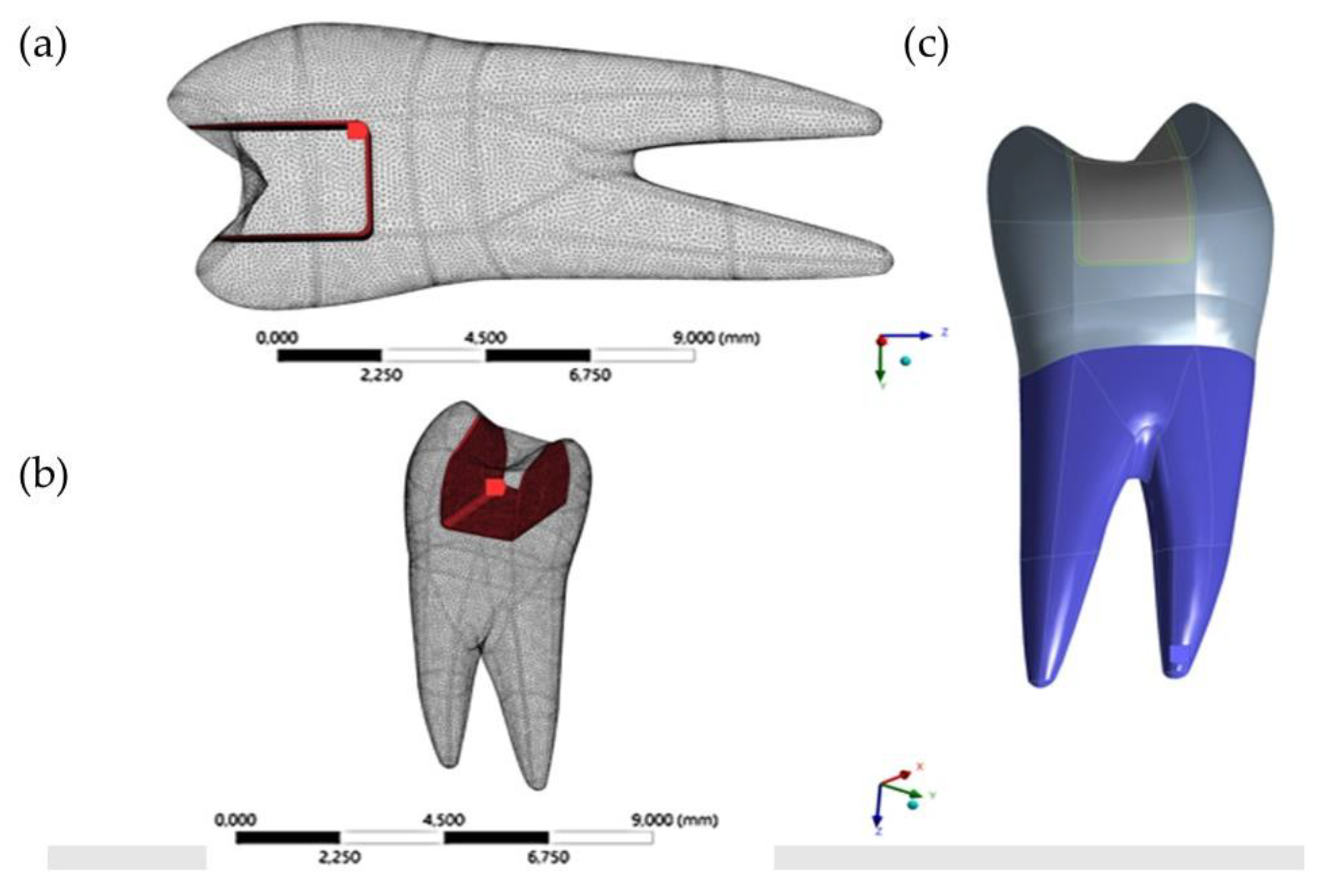
2. Materials and Methods
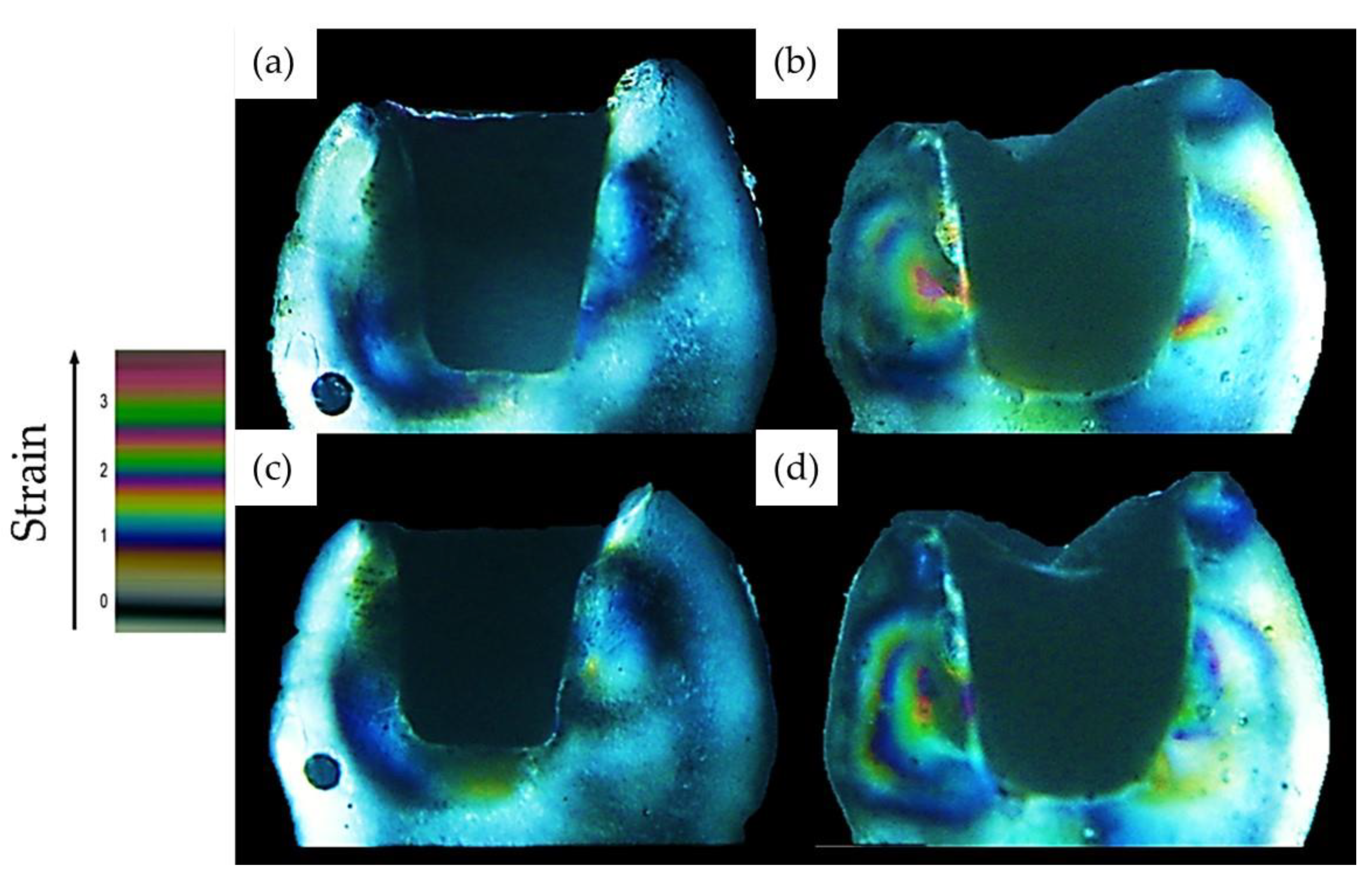
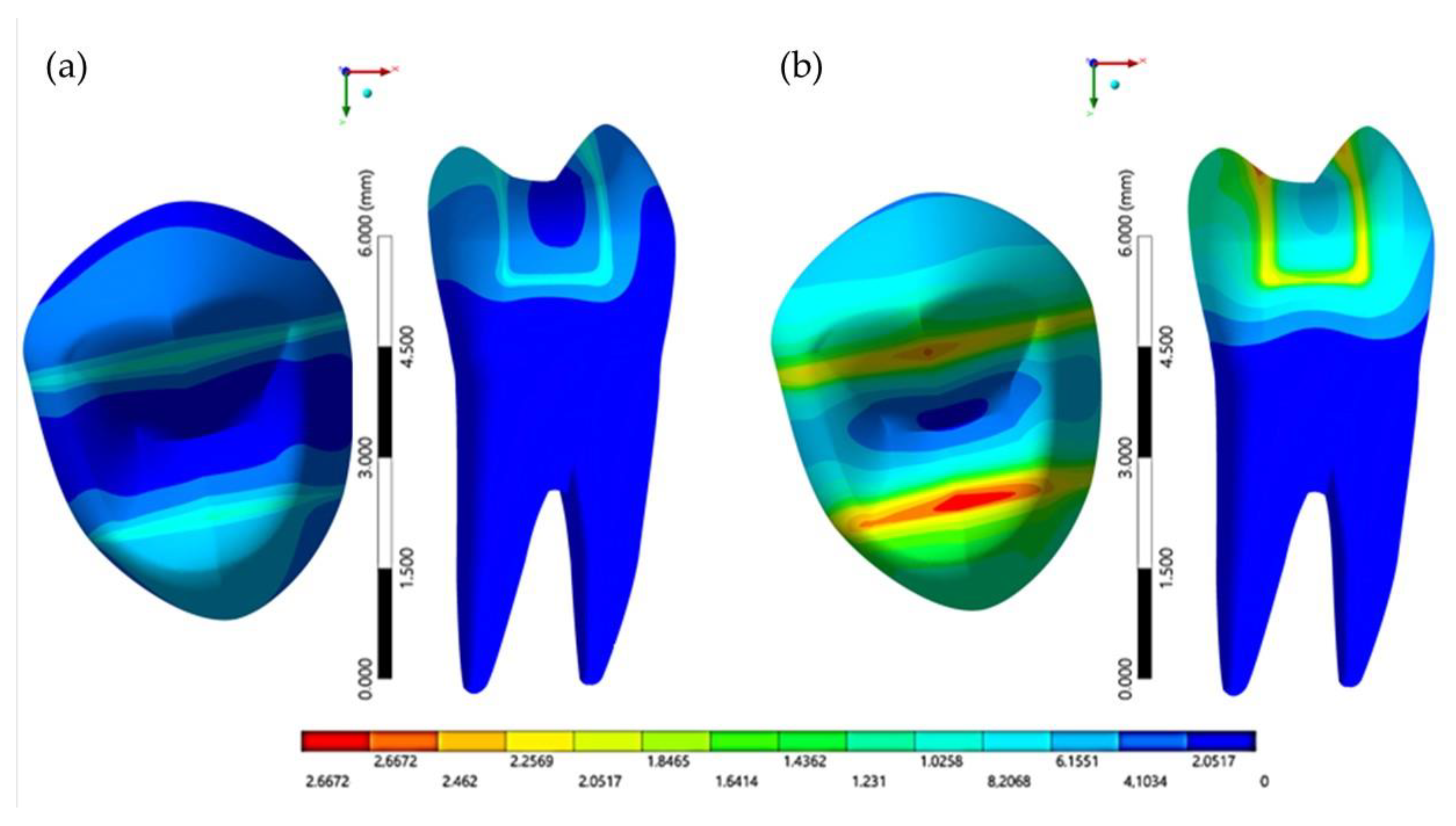
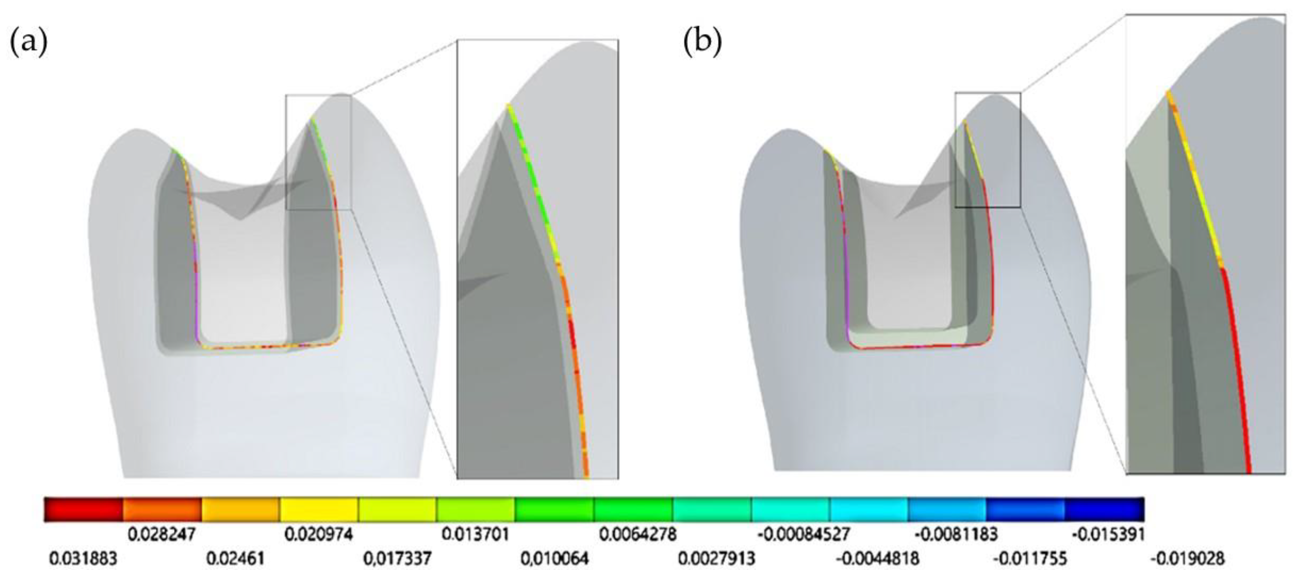
An upper first premolar was selected and prepared according to the following configurations: 6° diverged axial wall prepared by bur 3131 (KG Sorensen, São Paulo, Brazil), 5 mm occlusal isthmus, 2.0 mm proximal box height, 2.0 mm occlusal isthmus depth. This preparation was considered extensively in an attempt to simulate a critical condition of tooth structure loss. The tooth impression was performed using an addition silicone impression material (Express, 3M ESPE, Saint Paul, MN, USA) in a one-step technique.
The premolar samples were performed using photoelastic resin (n = 10) following the manufacturer’s instructions. Epoxy resin (Araldite®, TekBond, Saint Gobain, Embu das Artes, São Paulo, Brazil) and an epoxy resin hardener (Aradur®, Huntsman Container Corporation, Salt Lake City, UT, USA) were mixed (2:1). Then, the material was injected into the mold that was previously obtained. After that, the photoelastic resin premolars were stored in a container box and kept at room temperature for 72 h until complete resin polymerization.
After resin polymerization, the teeth were removed from the molds and stored at 37 °C for 24 h to allow residual stress release that might be present in the photoelastic resin. Before the cavity preparation, the photoelastic resin teeth were positioned between the polarizing filters to determine whether there was stress due to specimen fabrication or handling; if so, the teeth were stored again until completely releasing the stress.
Each premolar obtained in photoelastic resin received an indirect composite resin restoration. Different cement layers were considered for each group. In Group 1, a spacer layer was applied to simulate a cement layer with an average thickness of 100 μm. In Group 2, a spacer layer was applied to simulate a cement layer with an average thickness of 400 μm. After that, the impression was performed, and the composite resin inlays were fabricated (Grandioso S0, Voco) according to the manufacturer’s recommendations.
The inlay restoration was cleaned in an ultrasonic bath (Elma ultrasonic E15H, Singen, Germany) using distilled water for 15 s and dried with compressed air for 30 s. After that, the bonding agent (3M Single Bond, 3M ESPE, Saint Paul, MN, USA) was gently applied with a micro-brush in the cavity preparation to obtain a thin adhesive layer, then light-cured for 20 s (Poly Wireless, KAVo Kerr, Joinville, Santa Catarina, Brazil).
The resin cement (Rely X ARC, 3M ESPE, Saint Paul, MN, USA) was manipulated and applied to the restoration’s intaglio surface. Then, the restoration was positioned into the cavity under constant pressure (750 g), and any excess cement was removed. After that, light-curing for 40 s was applied at each side of the restoration.
After curing, each sample was placed between two flat polarizing filters over a white light forming a 90° angle to get a constant light field. The images obtained from the polariscope were captured by a professional digital camera. Based on the “Stress-Optics Law”, the stress generated by the polymerization shrinkage of the composite resin was analyzed qualitatively from the photoelastic fringes that formed in the photoelastic resin and the samples were compared after curing and 24 h. All samples were stored in a container at room temperature during the evaluation period.
The models (Figure 1) composed of enamel, dentin, pulp, indirect composite resin restoration, and resin cement were modeled with computer-aided design (CAD) software (Rhinoceros version 4.0 SR8, McNeel North America, Seattle, WA, USA) according to BioCad protocol (CTI Campinas, São Paulo, Brazil) [21]. The .stp file was exported to the computer-aided engineering (CAE) software (Ansys 15.0, ANSYS Inc., Houston, TX, USA) for the static structural analysis (Figure 2).
All materials were considered homogeneous, linear, elastic, and isotropic. The mechanical properties of all materials were taken from literature [22,23] and are summarized in Table 1.
The resin cement with polymerization shrinkage of 4.32% was simulated by the thermal analogy technique, where the value assigned to the linear coefficient of thermal expansion was 0.0000136 °C−1. The fixation support was performed in the root dentin external walls.
According to the modeling procedure, the resin cement layer was simulated in two thicknesses (100 and 400 μm), and the contact was considered perfectly bonded between cavity walls/cement and resin cement/inlay. The mesh with a 10-node quadratic tetrahedral element presented a total of 260,948 nodes and 148,845 elements. The convergence test was based on the number of nodes (260,948).

3. Results

The qualitative analysis was based on the “Stress-Optics Law” (Figure 3), where the birefringence components contributed by each component of plane stress and hottest color fringes indicate the presence of higher strain.
In the qualitative analysis of the images, photoelastic resin showed a higher strain in Group 2 (400 μm cement thickness) with the presence of a higher second-order fringe immediately and after 24 h. In Group 1 (100 μm cement thickness), a reduced formation of the first-order fringe was observed immediately and after 24 h. For FEA, the stress maps are summarized in Figure 4, Figure 5, Figure 6, Figure 7, Figure 8 and Figure 9.
The tensile stresses in the composite resin surface increased proportionally with the increase in the cement thickness and deformation of the cusps (Figure 3).
The greater deformation due to polymerization shrinkage was generated on the lingual cusp, especially in Group 2 (400 μm), and it was observed in places where the geometry changes the direction (axiopulpal angle).
The maximum principal stress values were also higher int the axiopulpal angle in both conditions, with the highest tensile stress values in the higher cement thickness group (Table 2).

4. Discussion

The aim of this study was to analyze the biomechanical behavior resulting from the polymerization of resin cements in two different thicknesses (100 and 400 µm) through photoelastic and finite element analysis. According to the results obtained, it was possible to observe that the null hypothesis was not accepted, since the different thicknesses of the cement layer shows different mechanical polymerization behavior and stress magnitude.
Indirect restorations have been widely used to restore extensively damaged teeth because they allow greater form and function control, in addition to reinforcing the remaining tooth structure [24,25]. Nowadays, conservative and minimally invasive preparations are more suitable compared to conventional techniques.
In endodontically treated teeth, indirect restorative techniques demonstrated improved fracture resistance in posterior teeth compared to direct techniques [26]. The study of [27] showed that the most suitable indirect restorations for these cases are endocrowns. For inlays, the fracture mode varied according to the preparation configuration. This shows that for endodontically treated teeth, the choice of indirect restoration must be made with caution in order to promote a balance between preserving the tooth structure and maximizing the strength of the restoration.
The adhesive factor is considered a critical point in the clinical success and long-term prognosis of minimally invasive restorations [28,29,30,31,32,33,34,35,36]. However, the present study demonstrates that the thickness of the resin cement layer affects the polymerization shrinkage and the cusp deflection.
The photoelastic images of this study allowed us to observe the deformations caused by the polymerization shrinkage of the resin cement. This shrinkage occurs due to the addition of monomer molecules into a polymer network, reducing the space between the original molecules [35]. The volumetric shrinkage can vary between 2–6%, generating stresses at the tooth–composite interface that can lead to micro-gap formation and composite debonding, besides cusp deflection. Unfortunately, due to the method’s limitation, the 24 h effect was not considered in the numerical simulation. Therefore, FEA is in agreement with photoelastic images after the luting procedure.
Rosa et al. (2015) [37] and Salaverry et al. (2013) [38] conducted studies that evaluated the effect that different resin cements have on cusp deflection after aging and on fracture resistance of inlay restorations, which corroborate with the findings of the present study, although cusp deflection can be higher or lower depending on factors such as the type of cement used, the layer cement thickness, and the loading type under the restoration. Rosa et al. had results showing that the application of a higher occlusal load produced an increase in the intercuspal distance, proving that the deformation depends on the intensity of the applied force under the restoration. For Salaverry and Dall Agnol et al. (2013) [39], resin inlays cemented with the same resin cement used in the present study (RelyX ARC) provided less cusp deflection after cyclic fatigue loading and promoted greater fracture resistance compared to self-adhesive resin cements. However, neither study evaluated the cement layer thickness, which also has an influence on the mechanical behavior of restorations. The present study confirms that the cement layer thickness can influence, with other factors, cusp deflection.
Studies showed that the vector resulting from volumetric shrinkage occurs in the central direction of the material volume, and the stress distribution is predominantly controlled by the free surface, adhesion resistance, and interface cracks [40,41,42,43]. This indicates that the pattern of isochromatic fringes formed in the photoelastic resin (Figure 2) was the result of the strain generated in the photoelastic resin, being superior in the group with higher cement thickness due to the more accentuated shrinkage during polymerization. The isochromatic fringes in the photoelastic resin can be correlated with the tensile stress between the bonded composite resin and the tooth preparation. Thereby, the group with a cement thickness of 100 µm (Group 1) presented less stress when compared to the group with a cement thickness of 400 µm (Group 2). Composites undergo volumetric shrinkage during polymerization, which can result in the development of residual stresses at the adhesive interface even after completion of the polymerization process [43]. For Group 2 (400 µm), bigger magnitudes of defined fringes were observed. The higher shrinkage stress after 24 h has been attributed to the crosslinking reaction that occurs after curing and to thermal shrinkage [44].
The cavity geometry and c-factor influence the flow of resin cement during the bonding procedure [45]. After adhesive bonding, the cement will be prevented from contracting freely. This leads to shrinkage stresses at the adhesive interface [39]. The result of present study is in agreement with the study conducted by Sokolowski et al. (2021) [40], which reported that higher shrinkage stresses are associated with thicker cement layers.
In the present study, in Group 2 (400 µm), the c-factor (ratio of the bonded to the unbonded surface area) [46] was 8.47 with a cement volume of 37.74 mm3. I Group 1 (100 µm), the c-factor was 31.23 and the cement volume was 11.36 mm3, which is consistent with other investigators. Sakaguchi (2012) [47] stated that the development of the shrinkage stress depends directly on the volume and stiffness of the composite. Rodrigues et al. (2012) [48] and Correa et al. (2014) [49] reported that stress generated by bonding of composite to the cavity is affected by the c-factor, remaining walls, and cement volume.
The stresses are directed to the restoration–cement and cement–substrate interfaces and are directly proportional to the modulus of elasticity of the restorative material [50]. The cavity configuration, quality of the substrate and the type of bonding can compensate the generated stresses in this region [51]. Regarding dental pulp, according to the literature, studies that used synthetic substrates to replace human teeth in laboratory tests do not report the presence or absence of the pulp chamber space and there are also no studies that assess the influence of the pulp chamber space on compressive forces in indirect restorations [52,53]. If the resistance capacity of the cavity walls is not sufficient to compensate generated stresses, it may result in de-bonding at the cement–restoration and/or cement–substrate interface. In this study, the tooth was simulated in photoelastic resin that has a modulus of elasticity lower than that of the natural tooth. Thus, the stress generated in the photoelastic resin is underestimated when compared to the natural tooth.
The magnitude of the stress in the resin cement can generate clinical complications such as microleakage, postoperative hypersensitivity, pulp damage, and recurrent caries [32,54,55,56].
A finite element study conducted by Li et al. (2008) [55] analyzed the stress concentration in Class I composite resin restorations. According to the results of this study, thicker restorations showed a stress concentration in the cavosurface margin, which is a critical factor in the marginal deterioration of restorations. The study also showed that polymerization shrinkage is the most important factor in developing residual stresses in restorations. The present study considered the qualitative analysis to evaluate the generated strains using photoelastic resin and quantitative analysis using the finite element method. The qualitative evaluation of the images has some disadvantages, as it does not show the specific mathematical value of the stress shrinkage of the analyzed composites. The results are obtained by means of visual analysis of the images then these results are compared between the groups. However, this direct method is practical and useful for comparing and validating values calculated with FEA [57]. FEA is an appropriate method to achieve the present study’s aim [57], but different tests such as Micro-CT, submicron digimatic micro-meter, or confocal laser scanning microscope (CLSM) should be performed in order to complement the present study’s results.
The thickness of the resin cement is considered a critical factor for the prognosis of indirect restorations. The present study showed that a greater thickness of cement increases the stress at the walls of the tooth as a result of the polymerization shrinkage. Therefore, a laboratory method must be developed to standardize the ideal thickness of resin cements for all types of indirect restorations. During the cementation of indirect restorations, the adequate control of cement thickness reduces the polymerization shrinkage and consequently the residual stress at the adhesive interface.

5. Conclusions

Within the limitations of this study, it was concluded that the thickness of resin cement affects the residual shrinkage stress and strain magnitude, causing higher cusp deflection when thicker cement layer was considered.

Author Contributions

Conceptualization, L.M.C., A.B.A.P., T.J.d.A.P.-J., C.P. and A.L.S.B.; methodology, L.M.C., A.B.A.P. and A.L.S.B.; software, A.L.S.B.; validation, T.J.d.A.P.-J., C.P. and A.L.S.B.; formal analysis, L.M.C., A.B.A.P. and A.L.S.B.; investigation, L.M.C., A.B.A.P., A.M.D. and A.L.S.B.; resources, T.J.d.A.P.-J., C.P. and A.L.S.B.; data curation, L.M.C., A.B.A.P. and A.M.D.; writing—original draft preparation, L.M.C., A.B.A.P., T.J.d.A.P.-J. and C.P.; writing—review and editing, L.M.C., A.B.A.P., A.M.D., T.J.d.A.P.-J., C.P. and A.L.S.B.; visualization, L.M.C., A.B.A.P. and A.L.S.B.; supervision, T.J.d.A.P.-J., C.P. and A.L.S.B.; project administration, A.L.S.B.; funding acquisition, T.J.d.A.P.-J., C.P. and A.L.S.B. All authors have read and agreed to the published version of the manuscript.

Funding

This research received no external funding.

Institutional Review Board Statement

Not applicable.

Informed Consent Statement

Not applicable.

Data Availability Statement

The data presented in this study are available on request from the corresponding author.

Conflicts of Interest

The authors declare no conflict of interest.

References

  1. Diaz-Arnold, A.M.; Vargas, M.A.; Haselton, D.R. Current status of luting agents for fixed prosthodontics. J. Prosthet. Dent. 1999, 81, 135–141. [Google Scholar] [CrossRef]
  2. de Matos, J.D.; Nakano, L.J.; Bottino, M.A.; de Jesus, R.H.; Maciel, L.C. Current considerations for dental ceramics and their respective union systems. Rev. Bras. Odontol. 2020, 77, e1768. [Google Scholar] [CrossRef]
  3. Menezes-Silva, R.; Velasco, S.R.; BRESCIANi, E.; Bastos, R.D.; Navarro, M.F. A prospective and randomized clinical trial evaluating the effectiveness of ART restorations with high-viscosity glass-ionomer cement versus conventional restorations with resin composite in Class II cavities of permanent teeth: Two-year follow-up. J. Appl. Oral Sci. 2021, 29, e20200609. [Google Scholar] [CrossRef]
  4. Ernst, C.P.; Meyer, G.R.; Klöcker, K.; Willershausen, B. Determination of polymerization shrinkage stress by means of a photoelastic investigation. Dent. Mater. 2004, 20, 313–321. [Google Scholar] [CrossRef]
  5. Charton, C.; Falk, V.; Marchal, P.; Pla, F.; Colon, P. Influence of Tg, viscosity and chemical structure of monomers on shrinkage stress in light-cured dimethacrylate-based dental resins. Dent. Mater. 2007, 23, 1447–1459. [Google Scholar] [CrossRef]
  6. Weinmann, W.; Thalacker, C.; Guggenberger, R. Siloranes in dental composites. Dent. Mater. 2005, 21, 68–74. [Google Scholar] [CrossRef]
  7. Feilzer, A.J.; De Gee, A.J.; Davidson, C.L. Increased wall-to-wall curing contraction in thin bonded resin layers. J. Dent. Res. 1989, 68, 48–50. [Google Scholar] [CrossRef]
  8. De Jager, N.; Pallav, P.; Feilzer, A.J. The influence of design parameters on the FEA-determined stress distribution in CAD-CAM produced all-ceramic dental crowns. Dent. Mater. 2005, 21, 242–251. [Google Scholar] [CrossRef]
  9. Ionescu, A.C.; Cazzaniga, G.; Ottobelli, M.; Ferracane, J.L.; Paolone, G.; Brambilla, E. In vitro biofilm formation on resin-based composites cured under different surface conditions. J. Dent. 2018, 77, 78–86. [Google Scholar] [CrossRef] [PubMed]
  10. Ozyesil, A.G.; Usumez, A.; Gunduz, B. The efficiency of different light sources to polymerize composite beneath a simulated ceramic restauration. J. Prosthet. Dent. 2004, 91, 151–157. [Google Scholar] [CrossRef]
  11. Arrais, C.A.; Rueggeberg, F.A.; Waller, J.L.; de Goes, M.F.; Giannini, M. Effect of curing mode on the polymerization characteristics of dual-cured resin cement systems. J. Dent. 2008, 36, 418–426. [Google Scholar] [CrossRef]
  12. Marinho, M.L.; Strazzi-Sayhon, H.B.; Moraes, J.C.; Assunção, W.G.; Dos Santos, P.H. Degree of conversion of resin cements polymerized under different ceramic systems. Gen. Dent. 2020, 68, 44–49. [Google Scholar] [PubMed]
  13. Rullman, I.; Patyna, M.; Janssen, B.; Willershausen, B. Determination of polymerization shrinkage of different composites using a photoelastic method. Am. J. Dent. 2017, 30, 16–22. [Google Scholar] [PubMed]
  14. Rullmann, I.; Schattenberg, A.; Marx, M.; Willershausen, B.; Ernst, C.P. Photoelastic determination of polymerization shrinkage stress in low-shrinkage resin composites. Schweiz. Mon. Zahnmed. 2012, 122, 294–299. [Google Scholar]
  15. Schwertner, A.; Almeida, R.R.; Gonini, A., Jr.; Almeida, M.R. Photoelastic analysis of stress generated by Connecticut Intrusion Arch (CIA). Dent. Press J. Orthod. 2017, 22, 57–64. [Google Scholar] [CrossRef] [Green Version]
  16. Kainose, K.; Nakajima, M.; Foxton, R.; Wakabayashi, N.; Tagami, J. Stress distribution in root filled teeth restored with various post and core techniques: Effect of post length and crown height. Int. Endod. J. 2015, 48, 1023–1032. [Google Scholar] [CrossRef]
  17. da Silva, J.V.; Martins, T.A.; Noritomi, P.Y. Scaffold informatics and biomimetic design: Three-dimensional medical reconstruction. Methods Mol. Biol. 2012, 868, 91–109. [Google Scholar] [PubMed]
  18. Kinomoto, Y.; Torii, M.; Takeshige, F.; Ebisu, S. Polymerization contraction stress of resin composite restorations in a model class I cavity configuration using photoelastic analysis. J. Esthet. Restor. Dent. 2000, 12, 309–319. [Google Scholar] [CrossRef] [PubMed]
  19. Correia, A.; Andrade, M.R.; Tribst, J.; Borges, A.; Caneppele, T. Influence of bulk-fill restoration on polymerization shrinkage stress and marginal gap formation in Class V restorations. Oper. Dent. 2020, 45, E207–E216. [Google Scholar] [CrossRef] [PubMed]
  20. Versluis, A.; Tantbirojn, D.; Pintado, M.R.; DeLong, R.; Douglas, W.H. Residual shrinkage stress distributions in molars after composite restoration. Dent. Mater. 2004, 20, 554–564. [Google Scholar] [CrossRef]
  21. Borges, A.L.; Borges, A.B.; Xavier, T.A.; Bottino, M.C.; Platt, J.A. Impact of quantity of resin, C-factor, and geometry on resin composite polymerization shrinkage stress in Class V restorations. Oper. Dent. 2014, 39, 144–151. [Google Scholar] [CrossRef]
  22. Noritomi, P.; Xavier, T.; Silva, J. A comparison between BioCAD and some known methods for finite element model generation. In Innovative Developments in Virtual and Physical Prototyping; CRC Press: Boca Raton, FL, USA, 2011; pp. 685–690. ISBN 9780415684187. [Google Scholar]
  23. Campaner, L.M.; Silveira, M.P.; de Andrade, G.S.; Borges, A.L.; Bottino, M.A.; Dal Piva, A.M.; Lo Giudice, R.; Ausiello, P.; Tribst, J.P. Influence of polymeric restorative materials on the stress distribution in posterior fixed partial dentures: 3D finite element analysis. Polymers 2021, 13, 758. [Google Scholar] [CrossRef] [PubMed]
  24. de Andrade, G.S.; Pinto, A.B.; Tribst, J.P.; Chun, E.P.; Borges, A.L.; de Siqueira Ferreira Anzaloni Saavedra, G. Does overlay preparation design affect polymerization shrinkage stress distribution? A 3D FEA study. Comput. Methods Biomech. Biomed. Eng. 2021, 1–10. [Google Scholar] [CrossRef] [PubMed]
  25. Ausiello, P.P.; Ciaramella, S.; Lanzotti, A.; Ventre, M.; Borges, A.L.; Tribst, J.P.; Dal Piva, A.; Garcia-Godoy, F. Mechanical behavior of Class I cavities restored by different material combinations under loading and polymerization shrinkage stress. A 3D-FEA study. Am. J. Dent. 2019, 32, 55–60. [Google Scholar] [PubMed]
  26. Scotti, N.; Coero Borga, F.A.; Alovisi, M.; Rota, R.; Pasqualini, D.; Berutti, E. Is fracture resistance of endodontically treated mandibular molars restored with indirect onlay composite restorations influenced by fibre post insertion? J. Dent. 2012, 40, 814–820. [Google Scholar] [CrossRef] [PubMed]
  27. Kassis, C.; Khoury, P.; Mehanna, C.Z.; Baba, N.Z.; Bou Chebel, F.; Daou, M.; Hardan, L. Effect of Inlays, Onlays and Endocrown Cavity Design Preparation on Fracture Resistance and Fracture Mode of Endodontically Treated Teeth: An In Vitro Study. J. Prosthodont. 2020. [Google Scholar] [CrossRef]
  28. Abad-Coronel, C.; Naranjo, B.; Valdiviezo, P. Adhesive systems used in indirect restorations cementation: Review of the literature. Dent. J. 2019, 7, 71. [Google Scholar] [CrossRef] [PubMed] [Green Version]
  29. Collares, K.; Corrêa, M.B.; Laske, M.; Kramer, E.; Reiss, B.; Moraes, R.R.; Huysmans, M.C.; Opdam, N.J. A practice-based research network on the survival of ceramic inlay/onlay restorations. Dent. Mater. 2016, 32, 687–694. [Google Scholar] [CrossRef]
  30. D’Arcangelo, C.; Vanini, L.; Casinelli, M.; Frascaria, M.; De Angelis, F.; Vadini, M.; D’Amario, M. Adhesive cementation of indirect composite inlays and onlays: A literature review. Compend. Contin. Educ. Dent. 2015, 36, 570–577, quiz 578. [Google Scholar] [PubMed]
  31. Yoshihara, K.; Nagaoka, N.; Sonoda, A.; Maruo, Y.; Makita, Y.; Okihara, T.; Irie, M.; Yoshida, Y.; Van Meerbeek, B. Effectiveness and stability of silane coupling agent incorporated in ‘universal’ adhesives. Dent. Mater. 2016, 32, 1218–1225. [Google Scholar] [CrossRef] [Green Version]
  32. Kim, J.Y.; Cho, G.Y.; Roh, B.D.; Shin, Y. Effect of curing mode on shear bond strength of self-adhesive cement to composite blocks. Materials 2016, 9, 210. [Google Scholar] [CrossRef] [PubMed] [Green Version]
  33. Dal Piva, A.M.; Tribst, J.P.; Jalkh, E.B.; Anami, L.C.; Bonfante, E.A.; Bottino, M.A. Minimal tooth preparation for posterior monolithic ceramic crowns: Effect on the mechanical behavior, reliability and translucency. Dent. Mater. 2021, 37, e140–e150. [Google Scholar] [CrossRef] [PubMed]
  34. Gomes de Carvalho, A.B.; de Andrade, G.S.; Mendes Tribst, J.P.; Grassi, E.D.; Ausiello, P.; Saavedra, G.D.; Bressane, A.; Marques de Melo, R.; Borges, A.L. Mechanical behavior of different restorative materials and onlay preparation designs in endodontically treated molars. Materials 2021, 14, 1923. [Google Scholar] [CrossRef] [PubMed]
  35. Ferracane, J.L.; Mitchem, J.C. Relationship between composite contraction stress and leakage in Class V cavities. Am. J. Dent. 2003, 16, 239–243. [Google Scholar] [PubMed]
  36. Kaisarly, D.; Gezawi, M.E. Polymerization shrinkage assessment of dental resin composites: A literature review. Odontology 2016, 104, 257–270. [Google Scholar] [CrossRef]
  37. da Rosa, H.C.; Marcondes, M.L.; de Souza, N.C.; Weber, J.B.; Spohr, A.M. Do resin cements influence the cuspal deflection of teeth restored with composite resin inlays? Acta Odontol. Latinoam. 2015, 28, 28–34. [Google Scholar]
  38. Salaverry, A.; Borges, G.A.; Mota, E.G.; Burnett Júnior, L.H.; Spohr, A.M. Effect of resin cements and aging on cuspal deflection and fracture resistance of teeth restored with composite resin inlays. J. Adhe. Dent. 2013, 15, 561–568. [Google Scholar]
  39. Dall Agnol, R.J.; Ghiggi, P.C.; Paranhos, M.P.; Borges, G.A.; Burnett, L.H., Jr.; Spohr, A.M. Influence of resin cements on cuspal deflection and fracture load of endodontically-treated teeth restored with composite inlays. Acta Odontol. Scand. 2013, 71, 664–670. [Google Scholar] [CrossRef]
  40. Sokolowski, G.; Krasowski, M.; Szczesio-Wlodarczyk, A.; Konieczny, B.; Sokolowski, J.; Bociong, K. The influence of cement layer thickness on the stress state of metal inlay restorations-photoelastic analysis. Materials 2021, 14, 599. [Google Scholar] [CrossRef]
  41. Braga, R.R.; Boaro, L.C.; Kuroe, T.; Azevedo, C.L.; Singer, J.M. Influence of cavity dimensions and their derivatives (volume and “C” factor) on shrinkage stress development and microleakage of composite restorations. Dent. Mater. 2006, 22, 818–823. [Google Scholar] [CrossRef]
  42. Hayashi, J.; Shimada, Y.; Tagami, J.; Sumi, Y.; Sadr, A. Real-time imaging of gap progress during and after composite polymerization. J. Dent. Res. 2017, 96, 992–998. [Google Scholar] [CrossRef]
  43. Ilie, N.; Jelen, E.; Clementino-Luedemann, T.; Hickel, R. Low-shrinkage composite for dental application. Dent. Mater. J. 2007, 26, 149–155. [Google Scholar] [CrossRef] [Green Version]
  44. Watts, D.C.; Satterthwaite, J.D. Axial shrinkage-stress depends upon both C-factor and composite mass. Dent. Mater. 2008, 24, 1–8. [Google Scholar] [CrossRef] [PubMed]
  45. Craig, R.G.; el-Ebrashi, M.K.; LePeak, P.J.; Peyton, F.A. Experimental stress analysis of dental restorations. I. Two-dimensional photoelastic stress analysis of inlays. J. Prosthet. Dent. 1967, 17, 277–291. [Google Scholar] [CrossRef]
  46. Feilzer, A.J.; De Gee, A.J.; Davidson, C.L. Setting stress in composite resin in relation to configuration of the restoration. J. Dent. Res. 1987, 66, 1636–1639. [Google Scholar] [CrossRef] [PubMed]
  47. Sakaguchi, R.; Powers, J. Restorative Materials. In Craig’s Restorative Dental Materials; Elsevier: Amsterdam, The Netherlands, 2019; pp. 135–170. ISBN 9780323478212. [Google Scholar]
  48. Rodrigues, F.P.; Silikas, N.; Watts, D.C.; Ballester, R.Y. Finite element analysis of bonded model Class I “restorations” after shrinkage. Dent. Mater. 2012, 28, 123–132. [Google Scholar] [CrossRef] [PubMed]
  49. de Oliveira Correia, A.M.; Tribst, J.P.; de Souza Matos, F.; Platt, J.A.; Caneppele, T.M.; Borges, A.L. Polymerization shrinkage stresses in different restorative techniques for non-carious cervical lesions. J. Dent. 2018, 76, 68–74. [Google Scholar] [CrossRef] [PubMed] [Green Version]
  50. Tribst, J.P.; Dal Piva, A.M.; de Melo, R.M.; Borges, A.L.; Bottino, M.A.; Özcan, M. Short communication: Influence of restorative material and cement on the stress distribution of posterior resin-bonded fixed dental prostheses: 3D finite element analysis. J. Mech. Behav. Biomed. Mater. 2019, 96, 279–284. [Google Scholar] [CrossRef] [PubMed]
  51. Kaisarly, D.; El Gezawi, M.; Nyamaa, I.; Rösch, P.; Kunzelmann, K.H. Effects of boundary condition on shrinkage vectors of a flowable composite in experimental cavity models made of dental substrates. Clin. Oral Investig. 2019, 23, 2403–2411. [Google Scholar] [CrossRef]
  52. Dal Piva, A.O.; Tribst, J.P.; Borges, A.L.; de Melo, R.M.; Bottino, M.A. Influence of substrate design for in vitro mechanical testing. J. Clin. Exp. Dent. 2019, 11, e119–e125. [Google Scholar] [CrossRef]
  53. Benazzi, S.; Nguyen, H.N.; Kullmer, O.; Hublin, J.J. Exploring the bio mechanics of taurodontism. J. Anat. 2015, 226, 180–188. [Google Scholar] [CrossRef] [PubMed] [Green Version]
  54. Al-Harbi, F.; Kaisarly, D.; Bader, D.; El Gezawi, M. Marginal integrity of bulk versus incremental fill class II composite restorations. Oper. Dent. 2016, 41, 146–156. [Google Scholar] [CrossRef] [PubMed] [Green Version]
  55. Li, J.; Li, H.; Fok, S.L. A mathematical analysis of shrinkage stress development in dental composite restorations during resin polymerization. Dent. Mater. 2008, 24, 923–931. [Google Scholar] [CrossRef] [PubMed]
  56. Tribst, J.P.; Dal Piva, A.M.; Ausiello, P.; Kalman, L. Influence of implant-abutment contact surfaces and prosthetic screw tightening on the stress concentration, fatigue life and microgap formation: A finite element analysis. Oral 2021, 1, 88–101. [Google Scholar] [CrossRef]
  57. Yeo, H.W.; Loo, M.Y.; Alkhabaz, M.; Li, K.C.; Choi, J.J.; Barazanchi, A. Bulk-fill direct restorative materials: An in vitro assessment of their physio-mechanical properties. Oral 2021, 1, 75–87. [Google Scholar] [CrossRef]
Figure 1. Finite element model showing: (a) coronal portion, restoration, and resin cement; (b) crown, root, prepared cavity, indirect composite resin restoration, and resin cement; (c) simulation of cemented indirect composite resin; (d) mesh obtained through the modeling software.
Oral 01 00017 g001
Figure 2. Finite element model showing: (a) cement layer mesh with perfectly bonded contact with the walls; (b) fixed support applied in the roots; (c) mesh generation in perspective view with the composite resin polymerization shrinkage.
Oral 01 00017 g002
Figure 3. Qualitative analysis: Group 1 with 100 μm thickness without forming first order fringes immediately (a) and after 24 h (c). Group 2 with 400 μm thickness showed second order fringe immediately (b) and after 24 h (d).
Oral 01 00017 g003
Figure 4. Cusp deflection as total deformation in (a) 100 μm cement thickness model and (b) 400 μm cement thickness. It is possible to see that the deflection cusp occurred with more intensity at the layer of highest thickness.
Oral 01 00017 g004
Figure 5. Maximum principal stress in the tooth with (a) 100 μm cement thickness model and (b) 400 μm cement thickness.
Oral 01 00017 g005
Figure 6. Maximum principal stress in the cement layer with (a) 100 μm cement thickness model and (b) 400 μm cement thickness.
Oral 01 00017 g006
Figure 7. Maximum principal stress in adhesive restoration surface with (a) 100 μm cement thickness model and (b) 400 μm cement thickness. The stress concentration was higher at the thickness of 400 µm.
Oral 01 00017 g007
Figure 8. Maximum principal stress at the cavity margin with (a) 400 μm cement thickness model and (b) 100 μm cement thickness. The stress concentration was higher at the vestibular occlusal region.
Oral 01 00017 g008
Figure 9. Maximum shear stress in the cavity margin with (a) 100 μm thickness cement model and (b) 400 μm thickness cement. It is possible to note that the shear stress was highest in the axiopulpal and buccal walls in the thicker group.
Oral 01 00017 g009
Table 1. Mechanical properties of materials: Young’s modulus, Poisson’s ratio, and linear shrinkage.
MaterialYoung’s
Modulus (GPa)
Poisson’s
Ratio
Volumetric Shrinkage (%)References
Dentin18.00.23-[18]
Enamel80.00.30-[18]
Cement layer7.00.241.74[19]
Composite resin200.20-[20]
Table 2. Quantitative analysis of cusp displacement, tooth stress, cement stress, and restoration stress according to the cement layer thickness.
ResultCement Layer Model
100 μm400 μm
Cusp displacement (mm)0.0001070.00026
Tooth stress (MPa)0.2100.305
Cement stress (MPa)0.2610.270
Restoration stress (MPa)0.2030.270
Publisher’s Note: MDPI stays neutral with regard to jurisdictional claims in published maps and institutional affiliations.

