
Advances of High-Performance Triboelectric Nanogenerators for Blue Energy Harvesting


1
Beijing Institute of Nanoenergy and Nanosystems, Chinese Academy of Sciences, Beijing 101400, China
2
School of Nanoscience and Technology, University of Chinese Academy of Sciences, Beijing 100049, China
3
CUSTech Institute, Wenzhou 325024, China
4
School of Materials Science and Engineering, Georgia Institute of Technology, Atlanta, GA 30332-0245, USA
*
Authors to whom correspondence should be addressed.
Nanoenergy Adv. 2021, 1(1), 32-57; https://0-doi-org.brum.beds.ac.uk/10.3390/nanoenergyadv1010003
Submission received: 8 July 2021
/
Revised: 17 August 2021
/
Accepted: 22 August 2021
/
Published: 26 August 2021
(This article belongs to the Special Issue Recent Advances in Nanogenerators)
Abstract
:The ocean is an enormous source of blue energy, whose exploitation is greatly beneficial for dealing with energy challenges for human beings. As a new approach for harvesting ocean blue energy, triboelectric nanogenerators (TENGs) show superiorities in many aspects over traditional technologies. Here, recent advances of TENGs for harvesting blue energy are reviewed, mainly focusing on advanced designs of TENG units for enhancing the performance, through which the response of the TENG unit to slow water agitations and the output power of the device are largely improved. Networking strategy and power management are also briefly discussed. As a promising clean energy technology, blue energy harvesting based on TENGs is expected to make great contributions for achieving carbon neutrality and developing self-powered marine systems.
1. Introduction
Covering over 70% of the earth’s surface, ocean plays a crucial role for lives on the planet and can be regarded as an enormous source of blue energy, whose exploitation is greatly beneficial for dealing with energy challenges for human beings [1,2,3]. With extreme climate conditions taking place more frequently nowadays, the world feels the urge to take immediate action to alleviate climate deterioration caused by global warming [4,5,6]. Carbon neutrality is thus put forward as a goal to reach balance between emitting and absorbing carbon in the atmosphere [7]. One of the most effective methods is to develop and expand the use of clean energy that generates power without carbon emission, such as the enormous blue energy [8]. Meanwhile, with the increasing activities in ocean, equipment deployed in the far ocean is facing problems regarding an in situ and sustainable power supply, where blue energy is an ideal source for developing new power solutions for such applications, allowing self-powered marine systems and platforms, though the harvesting scale can be much smaller [9,10,11].
The ocean blue energy is typically in five forms: wave energy, tidal energy, current energy, thermal energy, and osmotic energy, among which the wave energy is promising for its wide distribution, easy accessibility, and large reserves. The wave energy around the coastline is estimated to be more than 2 TW (1 TW = 1012 W) globally [12]. However, the present development of wave energy harvesting is challenged by its feature as a type of high-entropy energy, which refers to the chaotic, irregular waves with multiple amplitudes and constantly changing directions that are randomly distributed in the sea [13,14]. Most significantly, wave energy is typically distributed in a low-frequency regime, yet the most common and classic method of blue energy harvesting at status quo, the electromagnetic generator (EMG), performs rather poorly in low-frequency energy harvesting, which relies on propellers or other complex mechanical structures to drive bulky and heavy magnets and metal coils in order to transform mechanical energy into electricity [8]. Thus, it usually has high cost and low reliability.
First proposed by Wang in 2012 [15], the triboelectric nanogenerator (TENG, also called Wang generator) derived from Maxwell’s displacement current shows great prospect as a new technology to convert mechanical energy into electricity [16], based on the triboelectrification effect and electrostatic induction [17,18,19,20]. TENGs present superiorities including light weight, cost-effectiveness, easy fabrication, and versatile material choices [21,22,23,24,25]. The concept of harvesting blue energy using the TENG and its network was first brought out in 2014 [20]. As a new form of blue energy harvester, the TENG surpasses the EMG in that it intrinsically displays higher effectiveness under low frequency, owing to the unique feature of its output characteristics [22,26,27,28]. Moreover, adopting the distributed architecture of light-weighted TENG networks can make it more suitable for collecting wave energy of high entropy compared with EMGs, which are oversized in volume and mass [29,30,31,32,33].
Gaining attention, the material selection of TENGs, aimed at fulfilling their requirements and maximizing output, is governed by the mechanism. In triboelectrification process, surface charge density, a fundamental parameter regarding the performance of TENGs, relates to the electron affinity difference of triboelectric material pairs. As a result, polymers prevail as the dielectric layer since their various functional groups enhance charge transfer and capturing, as manifested in the triboelectric series, and they also possess the merits of excellent flexibility, scalability, and low cost [34] (Figure 1a). On top of that, as deduced from the Maxwell’s displacement current, other key factors contributing to output include dielectric permittivity, surface morphology, and robustness [35]. In addition, the rapid development of TENGs requires additional material properties that suit devices of various modes under conditioned application scenarios, such as a low friction coefficient for sliding mode TENGs, and high electrostatic breakdown strength and chemical stability for high-voltage TENG devices.
In this paper, recent advances of TENGs for harvesting wave energy are reviewed. The review mainly focuses on advanced designs of TENG units for enhancing the performance of wave energy harvesting, including rolling ball structure, multilayer structure, grating structure, pendulum structure, mass-spring structure, spacing structure, water-solid contact structure, and charge pumping strategy. Through such designs, the response of the TENG unit to slow wave agitations and the output power of the device are largely improved. Networking strategy and power management are also briefly discussed. Finally, further development challenges and the prospect of blue energy harvesting by the TENG are discussed.
2. TENG Systems for Blue Energy Harvesting
2.1. Fundamental Working Modes of TENGs
TENGs generate electricity by the coupling of triboelectrification and electrostatic induction, which are classified into the four fundamental working modes [19]: vertical contact-separation mode, lateral sliding mode, single-electrode mode, and freestanding triboelectric-layer mode (Figure 1b–e).
As shown in Figure 1b, in vertical contact-separation mode, the two dielectric surfaces are oppositely charged after physical contact due to triboelectrification. When the two surfaces are vertically separated with a gap in between, a potential drop is produced between the two electrodes attached to the backsides of the two dielectric layers due to the separation of positive and negative static charges, which drives current to flow between the electrically connected electrodes to balance the electrostatic field. When the gap vanishes, the potential drop due to static charges exists no more and so the induced free charges flow backwards. In this way, an alternate current (AC) output is generated in the external circuit under periodic contact and separation movement of the TENG [36].
For the lateral sliding mode shown in Figure 1c, the two dielectric surfaces are charged through triboelectrification during initial sliding motion. Under the full alignment of the two surfaces, no potential difference by static charges is created across the electrodes, since surface static charges of opposite signs completely compensate each other. When a relative displacement paralleled to the interface is introduced under lateral sliding, the mismatched area of the dielectric layers leads to bare static charges and so a potential difference appears between electrodes. The sliding back and forth of the TENG hence results in periodical changes of potential that drive free electrons to flow between the electrodes [37].
In single-electrode mode TENG (Figure 1d), the moving dielectric layer no longer has to be bound to electrodes or electrically connected by wires. The only electrode essential to the mode is one electrically connected to the ground, which can be regarded as another electrode. The surface of the dielectric layer is first charged under full contact with the electrode. When they start to move apart from each other, the induced charges in the electrode decrease in order to balance the electric potential, through charge exchange with the ground. Then, when the dielectric layer moves back to contact again, electrons flow in the opposite direction to re-establish an electrostatic equilibrium until the two surfaces fully overlap. Although charge transfer is not effective as a result of electrostatic screening effect, the triboelectric layer can move freely without any restrains [38].
The freestanding triboelectric-layer mode TENG can also work with the moving dielectric layer disconnected to electrodes, yet without any screening effect (Figure 1e). When the dielectric layer charged by triboelectrification approaches a pair of electrodes asymmetrically, a potential difference is induced across the two electrodes, causing electrons to flow between them to balance the local potential distribution. Under the back-and-forth movement of the dielectric layer, electrons oscillate across the paired electrodes, generating an AC current output [39].
2.2. TENG Systems for Harvesting Blue Energy
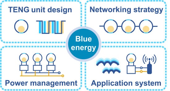
For effectively harvesting distributed wave energy, the TENG is conceived to be organized in networks, which can have hierarchical structure of modules [29]. The network structure also enables the device to be applied in different scales of harvesting, ranging from self-powered systems to large-scale clean energy (Figure 2a). In the development of TENGs for blue energy, efforts are mainly focusing on four aspects: TENG unit design, networking strategy, power management, and application system (Figure 2b). The primary and most significant part is the fundamental design of the TENG unit, which relies on continuous improvements focusing on the structure, principle, and material to enhance its energy harvesting performance and to meet demands raised by various ocean environments, both on the water surface and beneath it. Networking strategy is then adopted to add outputs of single TENG units and expand them in a reliable way. It decides the connection pattern of massive TENG units and the coupling effect between TENG units, which could further enhance the performance. Before finally supplying electricity power to the application system, power management is required to manipulate the TENG output for a better match with appliances and improve the power efficiency with circuit approaches. This review mainly emphasizes methods to advance the design of TENG units, which is the most challenging part, and networking strategy and power management are also discussed.
3. Advanced Designs of TENG Units for Blue Energy
3.1. Rolling Ball Structure
The rolling ball structure is the most fundamental and typical structure for blue energy harvesting based on TENGs [29,53,54]. The structure basically features a rolling ball inside a rocking spherical shell, which is simple and capable of rocking in water. Due to the small rolling friction, it can be sensitive to tiny wave agitations. Moreover, the structure naturally has a low frequency related to the size of the ball and shell, which can be tuned to reach resonance with water wave motion. Since the rolling ball normally functions as a freestanding triboelectric layer and no wire is connected to the ball, TENG units based on such a structure are durable. Wang et al. reported the rolling-ball-structured TENG based on the freestanding triboelectric-layer mode for the first time, which consists of one rolling nylon ball and two stationary electrodes covered by Kapton films [53] (Figure 3a). Wave vibration drives the ball to roll back and forth between electrodes, producing alternate current in the external circuit connecting the electrodes. However, due to the limited contact area and charge density, the output charge and current are relatively low, reaching only 24 nC.
Advancement on the structure includes the evolution of material and structure of the ball and shell components. As proposed by Xu et al., the UV-treated silicon rubber is adopted as the material for the rolling ball, since its softness can contribute to enhancing the real contact area and durability of the TENG units [54] (Figure 3b). The UV treatment enables Si−O−Si chain scission and oxidative conversion of radical groups in rubber, altering the electron affinity and strengthening triboelectrification with silicone rubber dielectric layer. In addition, microstructures are created on the dielectric surface by mixing polyformaldehyde particles into the rubber to make the surface less sticky, lowering the damping force, thus resulting in a high charge output of the TENG unit even under small agitations (Figure 3c). The charge output of single unit is improved to 72.6 nC.
For further enhancing the contact of the ball, Cheng et al. designed a TENG consisting of a soft liquid/silicone rolling ball and a hollow acrylic sphere attaching two Cu electrodes [55]. The silicone rubber is shaped in a hollow sphere for sufficient softness while containing water inside to ensure full contact (Figure 3d). In this way, the structure of triboelectric rubber can expand the contact area and generate charges as high as 500 nC, more than 10 times that of the conventional structure of polytetrafluoroethylene (PTFE) dielectric layer and hard core (Figure 3e). Systematically speaking, the energy harvesting performance of the soft-contact spherical TENG is largely affected by the contact area, which relates to many factors, including sphere hardness, fill rate, acceleration speed, and bulk density. A theoretical model based on contact electrification and mainly concerning the sphere hardness was quantitatively established by Guan et al. [56]. The result indicates that the dynamic contact of sphere is affected by core mass and fill rate, which is optimized at 83%.
Another improvement approach concerning the ball structure is adopting multiple balls. Yang et al. featured TENG units with a 3D electrode structure intercalated by fluorinated ethylene propylene (FEP) pellets in internal channels as the tribo-material [42] (Figure 3f). A pair of 3D-structured electrodes are made by electrode plates of connected copper layers on the substrates, largely enhancing the surface area of the electrodes and improving the utilization of the internal space of the shell. The device can output under different modes of external excitation as controlled by inertial forces and gravity. For harmonic translational mode, the increase in displacement extent and frequency leads to rapid rising of the transferred charges and current, obtaining a high charge output of 520 nC. Under impact translational mode, the structure of multiple rolling balls widens the current peak, boosting the peak power density and average power density to 32.6 W m−3 and 8.69 W m−3, respectively. Meanwhile, an average power density of 2.05 W m−3 can be achieved in real water waves agitated at 1.45 Hz (Figure 3g). Moreover, the amount of FEP pellets influences charge output due to the cancel-out of electrostatic induction by FEP pellets in the two 3D electrodes when more than half of the device volume is filled. Considering the evolution of the shell structure, a similar TENG structure reported by Pang et al. is characterized by nest-assembling multiple shells with decreasing sizes, with PTFE balls filled into the gap space between neighboring shells [57] (Figure 3h). On the interior of each shell, gaped Cu electrodes are painted with good adhesion, conductivity, and durability. The PTFE balls can move freely on electrode surfaces. Such unique structure design also improves the utilization of limited device volume and elevates the contact area between balls and electrodes.
Combining the TENG with the EMG by making the rolling ball magnetic is another enhancement method, which was achieved by Wu et al. The packaging hollow shell of the hybridized device is divided into four zones by acrylic disks, which are set for power management, EMG module, and TENG module, respectively [58] (Figure 3i). On one hand, the magnetic sphere drives the EMG module via electromagnetic induction, as two coils are embedded on both sides of the magnet; on the other hand, it motivates the mover by magnetic attractive force, since the mover is centered by a magnetic cylinder. Then, the mover can drive the TENG module through its interaction with PTFE friction layers adhered to Tai Chi-shaped electrodes. Eventually, such design can collect wave energy from any orientation. It was also placed on a buoy to test in lake Lanier. During 162 s, the electricity stored in a supercapacitor reached 1.64 mJ (Figure 3j).
3.2. Multilayer Structure
Considering that triboelectrification is a phenomenon happening at the surface, to improve the output, enhancing the contact area in a certain space with a multilayer structure should be an effective method. The strategy is realized in many different types of TENGs, and the output charge and power are greatly improved. The major challenge lies in the structure design to drive the complex structure by external agitations, which requires delicate structure designs.
An integrated multilayered TENG based on soft membrane was proposed by Xu et al. The structure includes the inner oscillator and the outer shell, which are connected by elastic bands to form a spring-levitated oscillator structure [43] (Figure 4a). The oscillator is based on air-driven soft membranes, which shape into air-pocket-like structures to split the air chamber into upper and lower parts. Accordingly, the electrodes of TENGs attached to the membranes form upper and lower multilayered TENG arrays. When the outer shell moves up and down as pushed by waves, the inner oscillator goes down and up relative to the shell and compresses the air chambers alternately. Differences in air pressure reshape membranes, making the upper and lower TENGs contact and separate periodically. Thus, the agitations from water waves can effectively drive the multilayered TENGs via the air-driven mechanism. The device with a series of integrated TENGs working simultaneously and effectively can produce high transferred charges of 15 μC per cycle (Figure 4b).
Similarly, Xu et al. reported a tower-like TENG structure consisting of multiple parallel connected units in one tubular block [59] (Figure 4c). In the unit, PTFE balls roll on 3D-printed arc surface shell, which is attached with two stationary electrodes coated by melt adhesive reticulation nylon film, forming a freestanding mode TENG. Only one rectifier is needed in a block since all PTFE balls move in the same phase under agitations. The structure is also capable of collecting water wave energy in arbitrary directions (Figure 4d).
Liu et al. reported a nodding duck-structured TENG that consists of external nodding duck blocks installed with shafts and bearings, and internal multitrack TENG units [60] (Figure 4e). Each unit is made up of a pair of Cu electrodes, free-rolling nylon balls, and dielectric layers placed on arc-shaped tracks. Together, they form a multilayer-structured TENGs of three layers that share electrodes and dielectric films, maximizing the utilization of internal space. A multiple-track structure was also introduced to avoid arbitrary movements of balls in different TENG layers. Upon triggering of external waves, nodding duck shell rotates around the shaft, leading balls to roll back and forth on the tracks. Under the combination of gravity, supporting force, and damping motion, an AC output is generated with a maximum peak power density of 4 W m−3 by one block at 800 MΩ under waves excited at 0.21 Hz (Figure 4f).
A spherical TENG that consists of a zigzag multilayered structure with spring assistance was proposed by Xiao [61] (Figure 4g). The multilayered structure is fabricated by deforming a thin Kapton film at evenly distanced intervals to serve as the substrate for five TENG units on both sides.
Liu et al. introduced an oblate spherical TENG structure, which is divided into the upper part for rough sea energy harvesting and the lower part for tranquil ocean energy collection [62] (Figure 4h). The upper part adopts a multilayer structure, which is composed of a pie iron and three arched units. The units are made up of two joint spring steel plates, one coated with FEP film. The upper part operates as the pie iron presses FEP film to contact the plates. The lower part is composed of a radial patterned FEP film with copper electrodes underneath, while another same-structured PET film is suspended above it. The lower part works as the external excitation triggers the iron shot to push FEP films into contact (shot on them) or separation (shot off them). Such structure also enhances self-stabilization and costs less, since the utilization of spring plates with good elasticity makes extra supporting structures for the units unnecessary.
Kim et al. reported a floating buoy-based TENG that contains a power generation unit and a height-adjustable support, which connects the unit to a floating buoy [47] (Figure 4i). There are four arrays of cylinder TENGs in the unit, each rotationally stacked upward for every 45°, forming a multilayered structure for energy harvesting in arbitrary directions. For each freestanding mode TENG, a solid PTFE bar oscillates inside a tube, with the outer surface of the tube being attached by four Cu electrodes. The height-adjustable support changes the force applied on the unit according to the alteration of the water wave amplitude. The acrylic protection layer can tolerate harsh environmental conditions.
3.3. Grating Structure
The grating structure is regarded as a high-performance TENG design that has superior output. It can convert low-frequency agitations to high-frequency electrical output through a periodic grating electrode pattern. However, large friction at the interface makes it difficult to be agitated by slow water waves.
Bai et al. proposed a radial-grating-disk-structured TENG, where every TENG unit is made of facing sides of a stator disk and a rotator disk, patterned with radial-grating-structured electrodes [46] (Figure 5a). The acrylic surface as one tribo-surface is frosted to reduce the friction force for easier agitation and better durability of the rotation device. In this way, the device can be successfully driven by the slow water waves, and the average power density of the device reaches 7.3 W m−3 at a wave frequency of 0.58 Hz (Figure 5b). Its capability of driving a self-powered total dissolved solids testing system is demonstrated (Figure 5c), indicating that the high-power wave energy harvester can be applied for in situ, real-time mapping of water quality.
3.4. Pendulum Structure
The pendulum structure features swinging mass blocks, which temporarily transform and store kinetic energy as potential energy to drive TENGs to output electricity. The structure inherently features with high sensitivity under mechanical excitations, and improves the energy conversion efficiency since pendulums can convert impact agitations to continuous swinging in its inherent frequency and can elongate the operation time of TENGs if the friction is small enough.
In this previously discussed work, Bai et al. set the TENG units of rotators and stators in a tandem with two swing mass blocks on both sides, together encapsulated in a waterproof acrylic shell [46] (Figure 5a). While stators are fixed on the shell, rotators are linked with swinging mass blocks by shafts; therefore, when the eccentric blocks are agitated by waves, rotators can rotate synchronously. The tandem structure allows unit expansion, which scales up the total output and reduces the matched resistance through simple parallel connection of units. As the number of units expends, the peak current increases from 8 μA to 120 μA, and the charge output raises from 0.2 μC to 3.4 μC, under a harmonic reciprocating rotation. When interacting with waves, the nature of the TENG in frequency response resulted by various configurations was revealed. An additional mass block is capable of adjusting frequency characteristics of the device, since changing block mass alters the resonant frequency of the TENG.
Other different types of pendulum structures are utilized as well to suit diverse designs of TENGs. Lin et al. reported a freestanding mode TENG that is mainly composed of an electrode layer, a pendulum triboelectric layer, and thin stripes [41] (Figure 5d). The pendulum is a copper layer capable of free oscillation with high sensitivity to excitations, since it is connected to the outer shell by a cotton thread. The electrode layers are an internal circular one and an external ring one, covered by PTFE films. Thin strips on the outer edge of acrylic shell act by electrification with the pendulum layer. Such design can be easily agitated to swinging and output electricity continuously (Figure 5e,f).
Jiang et al. proposed a TENG structure that consists of a bearing-based swing component and a cylindrical acrylic shell, whose internal surface is attached by equally sized Cu electrodes and PTFE stripes [63] (Figure 5g). The swing component is made of acrylic blocks with upper hollow and lower solid structures, the top and bottom of which are both adhered by arc-shaped acrylic strip. Swing motion of the block is realized by adding copper blocks to the bottom to lower the gravity center.
Apart from swinging pendulum devices, Hou et al. demonstrated a hybrid TENG adopting the rotational pendulum structure, which consists of a pendulum rotor, TENG blades, coils, and a cylindrical-tube-shaped frame [64] (Figure 5h). The pendulum rotor is made up of magnets twined by a copper ring, which are installed on the center shaft with ceramic bearings. The TENG blades connected in parallel are sandwiched flexible structure of FEP/Cu/FEP, with one side freestanding and the other side fixed on the frame. The blades and the Cu ring form the TENG part. The EMG is composed of coils that curl around the shaft and are embedded in the bottom, and the magnets of pendulum rotor, which are just above the coils. As the pendulum rotor rotates clockwise and anticlockwise around the shaft, a contact-separation mode TENG forms as the copper ring touches blades, and the EMG works under the periodic movement of magnets passing coils. The bearing support on the magnet rotor enables rotation even under tiny external excitations.
Another hybridized device reported by Chen et al. adopts a chaotic pendulum structure for the virtue of low working frequency [65] (Figure 5i). The chaotic pendulum consists of a major pendulum that swings back and forth under oscillation, and an inner pendulum that moves in a different chaotic manner following the major one. Both the TENG and the EMG are driven by the chaotic inner pendulum. The major pendulum of a weighted magnetic ball is used to enhance the oscillation frequency of the inner pendulum. The TENG is made of PTFE films and Au electrodes fixed on the inner swing. The EMG consists of the inner pendulum, which is composed of three magnetic balls evenly spaced on a rotating shaft, and three coils attached to the inside. When the main swing is pushed by water excitations, the freestanding mode TENG works based on the chaotic movement of the inner swing to send PTFE films moving back and forth on the electrodes, converting mechanical energy into electricity. The EMG part generates magnetic flux change of copper coils, as the magnetic balls begin moving under gravity and external magnetic incentive condition. The maximum output of the TENG reaches 15.21 μW and the EMG is up to 1.23 mW under an external excitation frequency of 2.5 Hz (Figure 5j).
To collect wave energy in all directions, Zhang et al. designed an active resonance TENG device that mainly integrates a simple pendulum, a floating tumbler, and flexible ring TENG [66] (Figure 5k). The tumbler intercepts wave energy, which is then captured by the pendulum, and finally transformed into electricity through TENGs. In the initial floating state, TENGs with flexible ring multilayered structure remain separate. The wave propagation makes the device lean aside; the pendulum thus brings the TENGs into full contact. A similar process proceeds as waves leave the system, generating two rounds of contact–separation output in one wave agitation. The pendulum with a circle-table-shaped core and the tumbler composed of a hemispherical float and a steel ball can create resonance effect by themselves, regardless of the external excitation frequency. Together with their damped motion, the energy harvesting efficiency is also enhanced. Moreover, the omnidirectional structural design ensures effective collection of omnidirectional water wave energy by the device.
3.5. Mass-Spring Structure
The mass-spring structure can produce oscillation under external agitations, which can be tuned to the frequency of the water waves to achieve resonance. It normally vibrates along the vertical direction with the effect of gravity. The structure shares the energy transfer mechanism of the pendulum structure, along with its merits.
Hu et al. reported a TENG built on a suspended 3D structure within a cube, which is a spiral with a seismic mass at the bottom that behaves like a spring [67] (Figure 6a). The top of the spiral is fixed to the inner top surface of the cube. One of TENG plates is attached to the bottom of the spiral, and the other plate is at bottom of the cube. Initially, the TENG plates slightly contact because the spiral is released. When the external disturbance pushes the cube’s bottom to displace, the seismic mass vibrates with it and so the spiral begins oscillation. TENG plates thus separate as a result of spiral contraction, forming a vertical contact-separation mode TENG. A maximum output power density of 2.76 W m−3 on a load of 6 MΩ can be achieved.
The previously discussed multilayered TENG structure raised by Xu et al. contains a spring-levitated oscillator, where the inner oscillator and the outer shell are connected by elastic bands [43] (Figure 4a). The shell acts as a mounting base that also protects the oscillator. Energy transfer is achieved by the oscillator, whose elastic bands provide elastic support for the oscillator both horizontally and perpendicularly, making it stable under movement. The device can oscillate several times under single agitation.
The work by Xiao et al. mentioned beforehand also contains multilayered TENG units that rely on the structure for energy conversion [61] (Figure 4g). Four flexible springs are to support the mass block, and four rigid springs are attached to the mass’s top to exert resilience force to press the TENG units upon wave excitation. Four shafts are also fixed for the mass and springs to move along with.
He et al. developed a mechanical regulator to drive TENGs with steady AC output, using the principle of auto-winding mechanical watch, which is to store random energy by transformation into potential energy and then release it at a designed pace [68] (Figure 6b). The structure involves more complex mechanisms by springs. The device consists of three parts: energy harvest and storage module, energy controllable release module, and energy conversion module. The first module contains input shaft, input gear train, and flat spiral spring, which transforms environmental energy into elastic potential energy. The second module is composed of escapement-spring-leaf and transmission gear train. The escapement-spring-leaf is an integration of hairspring system and escapement, in order to reserve their kinetic merits and simplify the transmission chain to reduce energy loss. The last module is made up of output gear train, one-way shaft system, flywheel, and TENG units. When the system works, the spiral spring is first compressed by wave movements, driving the rotor of TENGs to rotate under the control of the escapement-spring-leaf. With such design, constant output is realized under even a low frequency of 0.5 Hz and random working stimulations (Figure 6c).
3.6. Spacing Structure
The spacing structure introduces an air gap between the triboelectric layer and electrodes, which reduces friction and surface wear, thus enhancing the robustness and durability of the TENG device, and the triboelectric charges can be replenished by soft structures and intermittent contact.
The feature was first realized in the work by Lin et al. that has been discussed in the pendulum structure section. In the device, the pendulum triboelectric layer and electrode layer are not allowed to contact intimately [41] (Figure 5d). A freestanding gap is reserved to reduce material abrasion and enhance oscillation degree. Hence, the TENG device boosts superior durability for long time operation, with one trigger lasting for more than 120 s. PTFE soft structures around the electrodes allow a supplement of charges on the pendulum triboelectric layer.
In the work by Jiang et al., an air gap also exists between the interfaces of triboelectrification, namely, the surfaces of arc-shaped acrylic strips and Cu electrodes, as have been introduced in the pendulum structure section [63] (Figure 5g). Although the electrodes contact with PTFE brushes in the swing process for charge-replenishing purpose, the friction resistance is low. Moreover, the swing motion of disks relative to the central steel shaft is smoothed by bearings with lubrication oil. Apart from that, animal furs can also be adopted as low-friction materials to further reduce wearing and enhance charge output. As a result, the performance remains steady after 400,000 cycles (Figure 6d).
3.7. Water-Solid Contact Structure
The water-solid contact (L-S contact) structure involves two components: electrodes covered by dielectric films and liquid. The working mechanism includes two steps: firstly, charges are generated on the dielectric surface through L-S contact electrification; secondly, electrostatic induction works through the asymmetric screening of triboelectric charges by liquid. Here, liquid can be regarded as the freestanding layer, and so TENGs based on L-S contact are mainly in freestanding mode. Essentially, L-S contact TENGs can only operate under the condition that they are constantly shifting between the states of being submerged in liquid and emerging out of liquid. Surface charge density is enhanced since contact area is increased at the liquid-solid interface. Moreover, the structure includes no extra mechanical component. The friction at the interface is also suppressed.
The first work for wave energy harvesting based on the mechanism was proposed by Zhu et al. [51]. The specific working process of the TENG is described in Figure 7a. After L-S contact electrification, the FEP film is distributed with negative triboelectric charges. The partial submerge of electrode A by water wave induces an interfacial electrical double layer, formed by positive charges in water like hydroxonium to screen the negative surface charges on FEP. Accordingly, the potential difference between electrode A and B rises until B starts to dive into water too. When the whole device is submerged, triboelectric charges are completely screened by ions in water and no electrostatic induction exists any more (Figure 7b). In addition, the FEP film surface is intentionally patterned with hydrophobic nanowires to create nanoscale roughness. The modified surface can not only realize water infiltration into aligned nanowires to enlarge contact area, but also ensures immediate water repellency as water leaves the surface.
Further optimization focuses on the electrode structure, the film nanostructure, and liquid type. An integration approach was proposed by Zhao et al. that mounts bridge rectifier arrays on the TENG substrate surface to connect parallel electrodes together [44] (Figure 7c). Paralleled arrays of strip-shaped Cu electrodes are sputtered on Kapton substrate. The bridge rectifiers rectify currents between any pair of neighboring electrodes, by connecting pairs of adjacent electrodes through input pins, and linking all the negative output pins and positive output pins respectively to form comb-shaped joint cathode and insulated anode. In this way, the output can be added up to form pulsed direct current (DC) between the anode and cathode. The outermost electrification PTFE layer also protects and insulates all the conductive parts from water, with PTFE nanoparticles of 200 nm evenly distributed on its surface.
Zhao et al. further reported a TENG featuring a two-dimensional networked structure that yields high and stable output regardless of the wave type [69] (Figure 7d). The characteristic is realized through a rectifying chip based on p-n junction that is connected to both ends of electrode units, where the chip acts as a gate that only allows induced current from the anode to cathode. The electrode units in strip shape form a two-dimensional array on the Kapton substrate, and the two chips at the opposite sides of every electrode unit are in serial connection. A stable short circuit current of 13.5 μA and electric power of 1.03 mW are produced (Figure 7e).
As an intriguing structure design, the buoy-like TENG device proposed by Li et al. involves an outer TENG whose bottom electrode is on the outside, and an inner TENG whose bottom electrode is inside the buoy [70] (Figure 7f). As PTFE film rubs water, charges are induced on the surface, leading to a potential difference between the bottom electrode and the electrode on the backside of PTFE. The outer TENG works under up-down wave movements, while the parallel-connected inner TENGs function under shaking or rotation movements (Figure 7g,h). Consequently, the device can collect energy from different types of wave excitations.
The work constructed by Pan et al. aimed to study the influence of liquid properties on TENG output, by a U-tube TENG that includes a FEP U-tube, Cu electrodes, and liquid solution [71] (Figure 7i). The liquid flows on the coarsely nanostructured inner surface of the U-tube. As the U-tube rolls rightward or leftward and drives the liquid to overlap the FEP U-tube, currents are generated on the Cu electrodes wrapped outside the tube. It is concluded that liquid with higher polarity, dielectric constant, and contact angle yields higher output, and pure water, which is the eleventh specimen, showed the best experimental result in eleven types of liquids (Figure 7j).
3.8. Charge Pumping Strategy
As is known, the TENG is based on triboelectrification to generate static charges, and electrostatic induction to drive free charge transfer. However, the limited surface charge density by triboelectrification greatly hinders the output enhancement of TENGs [21]. Compared to other methods, developing new mechanisms on charge accumulation can address the issue fundamentally under ambient conditions.
The charge pumping strategy is shown to effectively enhance the charge density [45]. The utilization of the strategy requires a floating layer that can accumulate and bind large amounts of charges for electrostatic induction, and a charge pump that can pump charges into the floating layer simultaneously (Figure 8a). The realization of such mechanism involves a pump TENG, which is a normal TENG with a rectifier to make charge flow unidirectionally, and a main TENG (Figure 8b). The floating layer of M2 is achieved owing to the insulation from electrodes M1 and M3 of the main TENG by two dielectric layers, D1 and D2. Therefore, M2 cannot exchange charges with the main TENG electrodes and can only accept electron flow of one direction from the rectifier. The charge pumping process from the pump TENG to the main TENG is similar to charging a capacitor, and can last until the dielectric layers break down electrically. The pumped charges inside the floating layer are like static charges in normal TENGs, thus achieving large output through electrostatic induction. The energy collected by pump TENG adds up through charge accumulation in the main TENG, achieving an ultrahigh effective surface charge density of 1020 μC m−2 in ambient conditions, which does not rely on intensive rubbing or contact, improving energy efficiency (Figure 8c).
Another similar method reported by Liu et al. utilizes only one TENG combined with a self-voltage-multiplying circuit [72] (Figure 8d). Charge amplification is realized through altering the connection pattern of external capacitors accompanying the motion of the TENG. A voltage-multiplying circuit (VMC) module is adopted that can automatically switch the capacitors between parallel and serial connection during the contact and separation process of the TENG, owing to the unidirectional property of diodes. The doubled charge output from the VMC can flow back to the TENG in each cycle, thus greatly enhancing the charge density. A high output is achieved with a Zener diode for voltage stabilization (Figure 8e).
The work reported by Bai et al. develops a successful combination of charge pumping mechanism with rotation and sliding TENGs [73] (Figure 8f). The device is composed of a pump TENG and a main TENG, each with two disks as the rotator and the stator. A novel synchronous rotation structure is designed to allow direct injection of bound charges from the pump TENG to the main TENG. Specifically, an inversion structure allows the electrode disk of pump TENG to rotate, which is assembled with the main TENG by shafts to form the rotator, while the output electrodes of the main TENG are part of the stator. In this way, the electrodes of the pump TENG and storing bound charge layer can rotate in a synchronous mode. After the pump TENG injects charges into the storing electrodes of the main TENG, opposite charges are induced in the underlying output electrodes. Then, with the rotational sliding of storing electrodes, induced charges move following the motion of the bound charges, generating ultrahigh charge density and an average power density of 1.66 kW m−3 under a low drive frequency of 2 Hz (Figure 8g). Moreover, the decoupling of surface charge generation and friction enables lubricant to be applied to the interfaces to enhance durability. Ultrafast accumulation of bound charges is achieved in the rotation TENG that also possesses good expandability to charge multiple main TENGs by one pump TENG.
Wang et al. proposed a fundamentally different mechanism of charge shuttling to generate output on TENGs, which is not based on the electrostatic induction of static charges but on the shuttle of corralled charges in a TENG and a buffer capacitor [52] (Figure 8h). The corralled mirror charge carriers are accumulated through charge pumping strategy, and shuttle due to the interaction of two quasi-symmetrical conduction domains, which doubles the output. The device based on charge shuttling is composed of a pump TENG, a main TENG, and a buffer capacitor. The electrodes of the main TENG and the buffer capacitor form two conduction domains respectively presenting a quasi-symmetrical structure with Q+ side and Q- side. The pump TENG injects charges into domains through a rectifier. Upon contact and separation of the main TENG, its capacitance changes while that of the buffer capacitor remains, inducing a voltage difference between them to drive charges to shuttle in a quasi-symmetrical way, generating electricity on two loads. Consequently, the charge output is doubled by the two shuttling mirror charge carriers, achieving a total effective charge density of 1.5 mC m−2 with a Zener diode for stabilization (Figure 8i). The mechanism was successfully applied in an integrated device for wave energy harvesting. The peak current of the device reached about 1.3 mA under wave agitations of 0.625 Hz. The maximum peak power was 126.67 mW at 300 kΩ, corresponding to a volume power density of 30.24 W m−3 (Figure 8j).
4. Networking Strategy and Power Management
4.1. Networking Designs
The networking design of TENG units for blue energy harvesting involves mechanical connection and electrical networking. The ideal mechanical connecting method should be highly resilient, anti-fatigue, mechanically robust, and resistant to corrosion, while the electrical networking demands maximized output, avoidance of the disturbing electrostatic induction, and sufficient protection from the interference and corrosion by sea water. Meanwhile, the interconnection of TENG units is expected to introduce a coupling effect to enhance the total harvesting efficiency.
The coupled TENG network for wave energy harvesting was first realized by Xu et al. [54]. The work investigated the coupling design in details. Three connection methods were proposed and tested, of which the flexible connection shows higher efficiency and better performance (Figure 9a,b). The output of the linked unit is 10 times greater than that without linkage due to the coupling between TENG units. The network of 16 units is rectified and electrically connected for self-powered sensing by wave agitations (Figure 9c).
In order to enhance the robustness of mechanical connection, another intriguing way is to construct a network structure that can heal by itself after being broken by strong waves, as put forward by Yang et al. [42]. The idea was accomplished by the design of a self-adaptive magnetic joint (SAM-joint), which is composed of a rotatable spherical magnet and a limit block mounted around the TENG device shell (Figure 9d). The SAM-joint functions by self-adaptive mechanism of the pole and anisotropic restriction on the degree of freedom, enabling the network structure with characteristics of self-assembly, self-healing, and facile reconfiguration, which greatly improve the autonomy and robustness of the TENG network (Figure 9e).
Liu et al. put forward a study concerning four types of electrical networking topology [74]. The effect of wire resistance and output phase asynchrony of different units on the network output were analyzed and concluded to be crucial (Figure 9f).
Liu et al. designed a special type of plane-like power cable for TENGs to meet the demands raised by both electrical networking and mechanical linkage, which consists of spring steel tapes and three polymer films on the outside [48] (Figure 9g). Firstly, the plane shape that limits the entanglement among interconnected units, along with the highly resilient steel tape as the structural skeleton and the hydrophobic PTFE film, fulfills requirements for mechanical connection. Secondly, the conducting wires of TENGs are sandwiched in nearby steel tapes to avoid water screening effect for higher electrical output. Moreover, the power cable structure has an additional merit of generating electricity by the cable itself as a TENG device. Because as the cable contacts and separates with water, the steel tapes act as electrodes, which are covered by PTFE films, forming a L-S contact mode TENG.
4.2. Power Management
TENGs are generally characterized to have high internal impedance, which does not match the impedance of most general electronics. Direct powering the electronics by TENGs will result in low efficiency. Meanwhile, a switch strategy is required to maximize the power generated in a single cycle [21]. Moreover, for the network with multiple TENG units, there are new challenges to maximize the total output of modules or the whole network by power management.
The power management module (PMM) proposed by Xi et al. consists of two components: a tribotronic energy extractor to enhance the energy transfer efficiency from the TENG device to the circuit system, and a DC-DC buck converter to generate DC output on the load [49] (Figure 10a). The core goal of power management is to optimize and maximize the TENG output power on the loads through step-down flow, which is achieved by the PMM in a universal, efficient, and autonomous way because it is compact in size and applicable for various forms of TENGs with a self-management mechanism.
Xi et al. then utilized the PMM to support an application system based on wave energy [11] (Figure 10b). The harvested energy by TENGs passing through the PMM can drive a microprogrammed control unit (MCU), several microsensors, and a transmitter due to the enhanced energy transfer efficiency. The MCU based on an intelligent monitoring mechanism can deploy electricity for each sensor by varied priority and data transmission cycle, accomplishing a sustainable and autonomous wireless sensing for acceleration, magnetic intensity, and temperature.
Liang et al. proposed a hexagonal network of TENGs combined with the above PMM, successfully powering a wireless transmitter to send signals every 10 s under wave agitations, which further verified the application of the PMM in wave energy harvesting [75] (Figure 10c).
In addition, the transformer of switched-capacitor-convertor (SCC) is also a good candidate for power management since it is magnet-free, light-weight, and easy for integration (Figure 10d). Liu et al. put forward an SCC that adopts fractal design (FSCC), which optimizes the topology to decrease the impedance and lower the switch loss of transistors by integration on printing circuit boards [50]. FSCC also shows high step-down ratio and electrostatic voltage applicability. By coupling TENGs with FSCC, the power management system can boost the charge output 67 times (Figure 10e), and reaches a high power density of 954 W m−2 in pulse mode at 1 Hz (Figure 10f).
Apart from the above module, a switch circuit can also intensify the current and power output, as put forward in the mentioned multilayered air-membrane TENG by Xu et al. [47]. The switches are formed by attaching Al foils on air chambers and their corresponding contact spots on the outer shell, and are closed when matching foils contact. As the inner oscillator reaches its highest or lowest position and creates a voltage owing to the charge separation, switches are closed and a pulse current driven by the voltage appears in the external circuit (Figure 10g,h). Such switch circuit results in swift charge transfer that no longer depends on mechanical contact-separation speed of electrodes, rising the peak current to 1.77 A and the instantaneous power to 313 W, at a load of 100 Ω (Figure 10i), which further enhances previous experimental results by Cheng et al. [74]. Apart from that, the possible energy output per cycle is also increased, the principle of which was thoroughly discussed by Zi et al. [21].
5. Summary and Perspectives
In this paper, major aspects in the construction of TENG networks for blue energy harvesting are reviewed. The design of TENG unit for performance improvement is mainly discussed, from structure advancement to mechanism alteration, including rolling ball structure, multilayer structure, grating structure, pendulum structure, mass-spring structure, spacing structure, water-solid contact structure, and charge pumping strategy. Different kinds of structure designs are born with advantages to cater to specific needs, including the naturally low frequency of rolling ball structure to match with slow wave agitations, the superior output density of multilayer and grating structures, the high sensitivity and elongated operation time under mechanical excitations to improve the energy conversion efficiency through pendulum and mass-spring structures, and the outstanding robustness and durability by spacing structure. Principle innovation such as charge pumping is significant as it can bring large promotion to the system. Networking strategy and power management are also briefly discussed. As a promising clean energy technology, blue energy harvesting based on TENGs is expected to make great contributions for achieving carbon neutrality and developing self-powered marine systems. Revealed as a type of mechanical energy harvester more suitable for low-frequency excitations, the key to the commercialization of TENGs lies in the combination of high power density and robustness. The following aspects are suggested to be focused upon in future investigations:
(1) The design of TENG units is still quite crucial for further enhancing the power density, especially in a real ocean environment, which has much more complex wave conditions than in the lab, and the design of the device can be further validated and optimized based on current devices [76]. A detailed comparison on typical devices is shown in Table 1. In general, devices based on multilayer structure and grating structure intrinsically output with greater power density. Making the components soft can expand contact area, which enhances triboelectrification. Mechanism innovations regarding charge pumping strategy achieve ultrahigh charge density. Rolling ball, pendulum, and mass-spring structures can make blue energy harvesting more adaptive to changing directions and broad frequency of waves, with better durability. To reach higher output of TENGs from the material aspect, polymers can be improved in dielectric permittivity, electrostatic breakdown strength, stability, contact status, and mechanical robustness, through surface morphology and molecular functionalization as well as bulk composition modification [77].
(2) The durability of the TENG with friction or contact interfaces should be further examined and optimized. For long-term operation at sea, the device should achieve high reliability.
(3) The networking strategy is important for organizing and coupling TENG units together to reach higher efficiency as an integrated system. It is less investigated in the past for its complexity, which should be emphasized with further development of blue energy.
(4) The interaction of devices with water motion is crucial for power-take-off (PTO) performance of the system, which should be theoretically investigated and optimized based on fluid-structure interaction dynamics.
(5) Adaptability to the ocean environment involves packaging of the device, antifouling, and anticorrosion, which can ensure that the function of the network is not damaged in the severe ocean environment. The complete encapsulation of the device by waterproof materials can protect the circuit and core device from water.
(6) Hybrid harvesting that can harness various other energy forms at sea, such as wind, rain drops, and sun light, can further improve the utilization efficiency of certain ocean area [78].
(7) Environmentally friendly designs and degradable materials are also highly required to reduce the environment risks of such systems in ocean [79].
(8) Power management that optimizes at the module level or network level is highly required, which extends the present work to larger systems. It is expected to greatly improve the total efficiency of the whole system.
Author Contributions
Conceptualization, L.X. and Z.W.; writing—original draft preparation, H.W.; writing—review and editing, L.X. and Z.W.; supervision, L.X. and Z.W.; project administration, L.X. and Z.W.; funding acquisition, Z.W. and L.X. All authors have read and agreed to the published version of the manuscript.
Funding
This research was funded by the National Key R & D Project from Minister of Science and Technology, China (No. 2016YFA0202704), the Key Research Program of Frontier Sciences, CAS (ZDBS-LY-DQC025), National Natural Science Foundation of China (No. 51605033, 51735001), and Youth Innovation Promotion Association, CAS (No. 2019170).
Conflicts of Interest
The authors declare no conflict of interest.
References
- Isaacs, J.D.; Schmitt, W.R. Ocean Energy: Forms and Prospects. Science 1980, 207, 265. [Google Scholar] [CrossRef]
- Salter, S.H. Wave power. Nature 1974, 249, 720–724. [Google Scholar] [CrossRef]
- Ellabban, O.; Abu-Rub, H.; Blaabjerg, F. Renewable energy resources: Current status, future prospects and their enabling technology. Renew. Sust. Energ. Rev. 2014, 39, 748–764. [Google Scholar] [CrossRef]
- Marshall, B.; Ezekiel, C.; Gichuki, J.; Mkumbo, O.; Sitoki, L.; Wanda, F. Global warming is reducing thermal stability and mitigating the effects of eutrophication in Lake Victoria (East Africa). Nat. Preced. 2009. [Google Scholar] [CrossRef]
- Barbarossa, V.; Bosmans, J.; Wanders, N.; King, H.; Bierkens, M.F.P.; Huijbregts, M.A.J.; Schipper, A.M. Threats of global warming to the world’s freshwater fishes. Nat. Commun. 2021, 12, 1701. [Google Scholar] [CrossRef]
- Yamaguchi, M.; Chan, J.C.L.; Moon, I.-J.; Yoshida, K.; Mizuta, R. Global warming changes tropical cyclone translation speed. Nat. Commun. 2020, 11, 47. [Google Scholar] [CrossRef] [PubMed] [Green Version]
- van Soest, H.L.; den Elzen, M.G.J.; van Vuuren, D.P. Net-zero emission targets for major emitting countries consistent with the Paris Agreement. Nat. Commun. 2021, 12, 2140. [Google Scholar] [CrossRef]
- Tollefson, J. Power from the oceans: Blue energy. Nature 2014, 508, 302–304. [Google Scholar] [CrossRef] [Green Version]
- Qin, Y.; Alam, A.U.; Pan, S.; Howlader, M.M.R.; Ghosh, R.; Hu, N.-X.; Jin, H.; Dong, S.; Chen, C.-H.; Deen, M.J. Integrated water quality monitoring system with pH, free chlorine, and temperature sensors. Sens. Actuators B Chem. 2018, 255, 781–790. [Google Scholar] [CrossRef]
- Callaway, E. Energy: To catch a wave. Nature 2007, 450, 156–159. [Google Scholar] [CrossRef] [Green Version]
- Xi, F.; Pang, Y.; Liu, G.; Wang, S.; Li, W.; Zhang, C.; Wang, Z.L. Self-powered intelligent buoy system by water wave energy for sustainable and autonomous wireless sensing and data transmission. Nano Energy 2019, 61, 1–9. [Google Scholar] [CrossRef]
- Khaligh, A.; Onar, O.C. Energy Harvesting—Solar, Wind, and Ocean Energy Conversion Systems; CRC: Boca Raton, FL, USA, 2009; Volume 89. [Google Scholar]
- Chu, S.; Majumdar, A. Opportunities and challenges for a sustainable energy future. Nature 2012, 488, 294–303. [Google Scholar] [CrossRef] [PubMed]
- Wang, Z.L. Entropy theory of distributed energy for internet of things. Nano Energy 2019, 58, 669–672. [Google Scholar] [CrossRef]
- Fan, F.-R.; Tian, Z.-Q.; Wang, Z.L. Flexible triboelectric generator. Nano Energy 2012, 1, 328–334. [Google Scholar] [CrossRef]
- Wang, Z.L. On Maxwell’s displacement current for energy and sensors: The origin of nanogenerators. Mater. Today 2017, 20, 74–82. [Google Scholar] [CrossRef]
- Wang, Z.L.; Chen, J.; Lin, L. Progress in triboelectric nanogenerators as a new energy technology and self-powered sensors. Energy Environ. Sci. 2015, 8, 2250–2282. [Google Scholar] [CrossRef]
- Wu, C.; Wang, A.C.; Ding, W.; Guo, H.; Wang, Z.L. Triboelectric Nanogenerator: A Foundation of the Energy for the New Era. Adv. Energy Mater. 2019, 9, 1802906. [Google Scholar] [CrossRef]
- Niu, S.; Wang, Z.L. Theoretical systems of triboelectric nanogenerators. Nano Energy 2015, 14, 161–192. [Google Scholar] [CrossRef] [Green Version]
- Wang, Z.L. Triboelectric nanogenerators as new energy technology and self-powered sensors—Principles, problems and perspectives. Faraday Discuss. 2014, 176, 447–458. [Google Scholar] [CrossRef] [PubMed]
- Zi, Y.; Niu, S.; Wang, J.; Wen, Z.; Tang, W.; Wang, Z.L. Standards and figure-of-merits for quantifying the performance of triboelectric nanogenerators. Nat. Commun. 2015, 6, 8376. [Google Scholar] [CrossRef]
- Zi, Y.; Guo, H.; Wen, Z.; Yeh, M.-H.; Hu, C.; Wang, Z.L. Harvesting Low-Frequency (<5 Hz) Irregular Mechanical Energy: A Possible Killer Application of Triboelectric Nanogenerator. ACS Nano 2016, 10, 4797–4805. [Google Scholar] [CrossRef]
- Wang, J.; Li, S.; Yi, F.; Zi, Y.; Lin, J.; Wang, X.; Xu, Y.; Wang, Z.L. Sustainably powering wearable electronics solely by biomechanical energy. Nat. Commun. 2016, 7, 12744. [Google Scholar] [CrossRef] [PubMed] [Green Version]
- Bae, J.; Lee, J.; Kim, S.; Ha, J.; Lee, B.-S.; Park, Y.; Choong, C.; Kim, J.-B.; Wang, Z.L.; Kim, H.-Y.; et al. Flutter-driven triboelectrification for harvesting wind energy. Nat. Commun. 2014, 5, 4929. [Google Scholar] [CrossRef] [Green Version]
- Xiong, J.; Cui, P.; Chen, X.; Wang, J.; Parida, K.; Lin, M.-F.; Lee, P.S. Skin-touch-actuated textile-based triboelectric nanogenerator with black phosphorus for durable biomechanical energy harvesting. Nat. Commun. 2018, 9, 4280. [Google Scholar] [CrossRef] [Green Version]
- Kim, W.J.; Vivekananthan, V.; Khandelwal, G.; Chandrasekhar, A.; Kim, S.-J. Encapsulated Triboelectric–Electromagnetic Hybrid Generator for a Sustainable Blue Energy Harvesting and Self-Powered Oil Spill Detection. ACS Appl. Electron. Mater. 2020, 2, 3100–3108. [Google Scholar] [CrossRef]
- Chen, H.; Wang, J.; Ning, A. Optimization of a Rolling Triboelectric Nanogenerator Based on the Nano–Micro Structure for Ocean Environmental Monitoring. ACS Omega 2021, 6, 21059–21065. [Google Scholar] [CrossRef]
- Yuan, Z.; Wang, C.; Xi, J.; Han, X.; Li, J.; Han, S.-T.; Gao, W.; Pan, C. Spherical Triboelectric Nanogenerator with Dense Point Contacts for Harvesting Multidirectional Water Wave and Vibration Energy. ACS Energy Lett. 2021, 6, 2809–2816. [Google Scholar] [CrossRef]
- Wang, Z.L. Catch wave power in floating nets. Nature 2017, 542, 159–160. [Google Scholar] [CrossRef]
- Wang, Z.L.; Jiang, T.; Xu, L. Toward the blue energy dream by triboelectric nanogenerator networks. Nano Energy 2017, 39, 9–23. [Google Scholar] [CrossRef]
- Chen, H.; Xing, C.; Li, Y.; Wang, J.; Xu, Y. Triboelectric nanogenerators for a macro-scale blue energy harvesting and self-powered marine environmental monitoring system. Sustain. Energy Fuels 2020, 4, 1063–1077. [Google Scholar] [CrossRef]
- Jurado, U.T.; Pu, S.H.; White, N.M. Grid of hybrid nanogenerators for improving ocean wave impact energy harvesting self-powered applications. Nano Energy 2020, 72, 104701. [Google Scholar] [CrossRef]
- Rodrigues, C.; Ramos, M.; Esteves, R.; Correia, J.; Clemente, D.; Gonçalves, F.; Mathias, N.; Gomes, M.; Silva, J.; Duarte, C.; et al. Integrated study of triboelectric nanogenerator for ocean wave energy harvesting: Performance assessment in realistic sea conditions. Nano Energy 2021, 84, 105890. [Google Scholar] [CrossRef]
- Zou, H.; Zhang, Y.; Guo, L.; Wang, P.; He, X.; Dai, G.; Zheng, H.; Chen, C.; Wang, A.C.; Xu, C.; et al. Quantifying the triboelectric series. Nat. Commun. 2019, 10, 1427. [Google Scholar] [CrossRef] [Green Version]
- Wang, Z.L. On the first principle theory of nanogenerators from Maxwell’s equations. Nano Energy 2020, 68, 104272. [Google Scholar] [CrossRef]
- Niu, S.; Wang, S.; Lin, L.; Liu, Y.; Zhou, Y.S.; Hu, Y.; Wang, Z.L. Theoretical study of contact-mode triboelectric nanogenerators as an effective power source. Energy Environ. Sci. 2013, 6, 3576–3583. [Google Scholar] [CrossRef]
- Niu, S.; Liu, Y.; Wang, S.; Lin, L.; Zhou, Y.S.; Hu, Y.; Wang, Z.L. Theory of Sliding-Mode Triboelectric Nanogenerators. Adv. Mater. 2013, 25, 6184–6193. [Google Scholar] [CrossRef]
- Niu, S.; Liu, Y.; Wang, S.; Lin, L.; Zhou, Y.S.; Hu, Y.; Wang, Z.L. Theoretical Investigation and Structural Optimization of Single-Electrode Triboelectric Nanogenerators. Adv. Funct. Mater. 2014, 24, 3332–3340. [Google Scholar] [CrossRef]
- Niu, S.; Liu, Y.; Chen, X.; Wang, S.; Zhou, Y.S.; Lin, L.; Xie, Y.; Wang, Z.L. Theory of freestanding triboelectric-layer-based nanogenerators. Nano Energy 2015, 12, 760–774. [Google Scholar] [CrossRef] [Green Version]
- Wang, Z.L. From contact-electrification to triboelectric nanogenerators. Rep. Prog. Phys. 2021. [Google Scholar] [CrossRef]
- Lin, Z.; Zhang, B.; Guo, H.; Wu, Z.; Zou, H.; Yang, J.; Wang, Z.L. Super-robust and frequency-multiplied triboelectric nanogenerator for efficient harvesting water and wind energy. Nano Energy 2019, 64, 103908. [Google Scholar] [CrossRef]
- Yang, X.; Xu, L.; Lin, P.; Zhong, W.; Bai, Y.; Luo, J.; Chen, J.; Wang, Z.L. Macroscopic self-assembly network of encapsulated high-performance triboelectric nanogenerators for water wave energy harvesting. Nano Energy 2019, 60, 404–412. [Google Scholar] [CrossRef]
- Xu, L.; Pang, Y.; Zhang, C.; Jiang, T.; Chen, X.; Luo, J.; Tang, W.; Cao, X.; Wang, Z.L. Integrated triboelectric nanogenerator array based on air-driven membrane structures for water wave energy harvesting. Nano Energy 2017, 31, 351–358. [Google Scholar] [CrossRef]
- Zhao, X.J.; Zhu, G.; Fan, Y.J.; Li, H.Y.; Wang, Z.L. Triboelectric Charging at the Nanostructured Solid/Liquid Interface for Area-Scalable Wave Energy Conversion and Its Use in Corrosion Protection. ACS Nano 2015, 9, 7671–7677. [Google Scholar] [CrossRef]
- Xu, L.; Bu, T.Z.; Yang, X.D.; Zhang, C.; Wang, Z.L. Ultrahigh charge density realized by charge pumping at ambient conditions for triboelectric nanogenerators. Nano Energy 2018, 49, 625–633. [Google Scholar] [CrossRef]
- Bai, Y.; Xu, L.; He, C.; Zhu, L.; Yang, X.; Jiang, T.; Nie, J.; Zhong, W.; Wang, Z.L. High-performance triboelectric nanogenerators for self-powered, in-situ and real-time water quality mapping. Nano Energy 2019, 66, 104117. [Google Scholar] [CrossRef]
- Kim, D.Y.; Kim, H.S.; Kong, D.S.; Choi, M.; Kim, H.B.; Lee, J.-H.; Murillo, G.; Lee, M.; Kim, S.S.; Jung, J.H. Floating buoy-based triboelectric nanogenerator for an effective vibrational energy harvesting from irregular and random water waves in wild sea. Nano Energy 2018, 45, 247–254. [Google Scholar] [CrossRef]
- Liu, G.; Xiao, L.; Chen, C.; Liu, W.; Pu, X.; Wu, Z.; Hu, C.; Wang, Z.L. Power cables for triboelectric nanogenerator networks for large-scale blue energy harvesting. Nano Energy 2020, 75, 104975. [Google Scholar] [CrossRef]
- Xi, F.; Pang, Y.; Li, W.; Jiang, T.; Zhang, L.; Guo, T.; Liu, G.; Zhang, C.; Wang, Z.L. Universal power management strategy for triboelectric nanogenerator. Nano Energy 2017, 37, 168–176. [Google Scholar] [CrossRef]
- Liu, W.; Wang, Z.; Wang, G.; Zeng, Q.; He, W.; Liu, L.; Wang, X.; Xi, Y.; Guo, H.; Hu, C.; et al. Switched-capacitor-convertors based on fractal design for output power management of triboelectric nanogenerator. Nat. Commun. 2020, 11, 1883. [Google Scholar] [CrossRef] [Green Version]
- Zhu, G.; Su, Y.; Bai, P.; Chen, J.; Jing, Q.; Yang, W.; Wang, Z.L. Harvesting Water Wave Energy by Asymmetric Screening of Electrostatic Charges on a Nanostructured Hydrophobic Thin-Film Surface. ACS Nano 2014, 8, 6031–6037. [Google Scholar] [CrossRef]
- Wang, H.; Xu, L.; Bai, Y.; Wang, Z.L. Pumping up the charge density of a triboelectric nanogenerator by charge-shuttling. Nat. Commun. 2020, 11, 4203. [Google Scholar] [CrossRef]
- Wang, X.; Niu, S.; Yin, Y.; Yi, F.; You, Z.; Wang, Z.L. Triboelectric Nanogenerator Based on Fully Enclosed Rolling Spherical Structure for Harvesting Low-Frequency Water Wave Energy. Adv. Energy Mater. 2015, 5, 1501467. [Google Scholar] [CrossRef]
- Xu, L.; Jiang, T.; Lin, P.; Shao, J.J.; He, C.; Zhong, W.; Chen, X.Y.; Wang, Z.L. Coupled Triboelectric Nanogenerator Networks for Efficient Water Wave Energy Harvesting. ACS Nano 2018, 12, 1849–1858. [Google Scholar] [CrossRef]
- Cheng, P.; Guo, H.; Wen, Z.; Zhang, C.; Yin, X.; Li, X.; Liu, D.; Song, W.; Sun, X.; Wang, J.; et al. Largely enhanced triboelectric nanogenerator for efficient harvesting of water wave energy by soft contacted structure. Nano Energy 2019, 57, 432–439. [Google Scholar] [CrossRef]
- Guan, D.; Cong, X.; Li, J.; Shen, H.; Zhang, C.; Gong, J. Quantitative characterization of the energy harvesting performance of soft-contact sphere triboelectric nanogenerator. Nano Energy 2021, 87, 106186. [Google Scholar] [CrossRef]
- Pang, Y.; Chen, S.; Chu, Y.; Wang, Z.L.; Cao, C. Matryoshka-inspired hierarchically structured triboelectric nanogenerators for wave energy harvesting. Nano Energy 2019, 66, 104131. [Google Scholar] [CrossRef]
- Wu, Z.; Guo, H.; Ding, W.; Wang, Y.-C.; Zhang, L.; Wang, Z.L. A Hybridized Triboelectric–Electromagnetic Water Wave Energy Harvester Based on a Magnetic Sphere. ACS Nano 2019, 13, 2349–2356. [Google Scholar] [CrossRef]
- Xu, M.; Zhao, T.; Wang, C.; Zhang, S.L.; Li, Z.; Pan, X.; Wang, Z.L. High Power Density Tower-like Triboelectric Nanogenerator for Harvesting Arbitrary Directional Water Wave Energy. ACS Nano 2019, 13, 1932–1939. [Google Scholar] [CrossRef]
- Liu, L.; Yang, X.; Zhao, L.; Hong, H.; Cui, H.; Duan, J.; Yang, Q.; Tang, Q. Nodding Duck Structure Multi-track Directional Freestanding Triboelectric Nanogenerator toward Low-Frequency Ocean Wave Energy Harvesting. ACS Nano 2021, 15, 9412–9421. [Google Scholar] [CrossRef]
- Xiao, T.X.; Liang, X.; Jiang, T.; Xu, L.; Shao, J.J.; Nie, J.H.; Bai, Y.; Zhong, W.; Wang, Z.L. Spherical Triboelectric Nanogenerators Based on Spring-Assisted Multilayered Structure for Efficient Water Wave Energy Harvesting. Adv. Funct. Mater. 2018, 28, 1802634. [Google Scholar] [CrossRef]
- Liu, G.; Guo, H.; Xu, S.; Hu, C.; Wang, Z.L. Oblate Spheroidal Triboelectric Nanogenerator for All-Weather Blue Energy Harvesting. Adv. Energy Mater. 2019, 9, 1900801. [Google Scholar] [CrossRef]
- Jiang, T.; Pang, H.; An, J.; Lu, P.; Feng, Y.; Liang, X.; Zhong, W.; Wang, Z.L. Robust Swing-Structured Triboelectric Nanogenerator for Efficient Blue Energy Harvesting. Adv. Energy Mater. 2020, 10, 2000064. [Google Scholar] [CrossRef]
- Hou, C.; Chen, T.; Li, Y.; Huang, M.; Shi, Q.; Liu, H.; Sun, L.; Lee, C. A rotational pendulum based electromagnetic/triboelectric hybrid-generator for ultra-low-frequency vibrations aiming at human motion and blue energy applications. Nano Energy 2019, 63, 103871. [Google Scholar] [CrossRef]
- Chen, X.; Gao, L.; Chen, J.; Lu, S.; Zhou, H.; Wang, T.; Wang, A.; Zhang, Z.; Guo, S.; Mu, X.; et al. A chaotic pendulum triboelectric-electromagnetic hybridized nanogenerator for wave energy scavenging and self-powered wireless sensing system. Nano Energy 2020, 69, 104440. [Google Scholar] [CrossRef]
- Zhang, C.; He, L.; Zhou, L.; Yang, O.; Yuan, W.; Wei, X.; Liu, Y.; Lu, L.; Wang, J.; Wang, Z.L. Active resonance triboelectric nanogenerator for harvesting omnidirectional water-wave energy. Joule 2021, 5, 1613–1623. [Google Scholar] [CrossRef]
- Hu, Y.; Yang, J.; Jing, Q.; Niu, S.; Wu, W.; Wang, Z.L. Triboelectric Nanogenerator Built on Suspended 3D Spiral Structure as Vibration and Positioning Sensor and Wave Energy Harvester. ACS Nano 2013, 7, 10424–10432. [Google Scholar] [CrossRef]
- He, G.; Luo, Y.; Zhai, Y.; Wu, Y.; You, J.; Lu, R.; Zeng, S.; Wang, Z.L. Regulating random mechanical motion using the principle of auto-winding mechanical watch for driving TENG with constant AC output—An approach for efficient usage of high entropy energy. Nano Energy 2021, 87, 106195. [Google Scholar] [CrossRef]
- Zhao, X.J.; Kuang, S.Y.; Wang, Z.L.; Zhu, G. Highly Adaptive Solid–Liquid Interfacing Triboelectric Nanogenerator for Harvesting Diverse Water Wave Energy. ACS Nano 2018, 12, 4280–4285. [Google Scholar] [CrossRef]
- Li, X.; Tao, J.; Wang, X.; Zhu, J.; Pan, C.; Wang, Z.L. Networks of High Performance Triboelectric Nanogenerators Based on Liquid–Solid Interface Contact Electrification for Harvesting Low-Frequency Blue Energy. Adv. Energy Mater. 2018, 8, 1800705. [Google Scholar] [CrossRef]
- Pan, L.; Wang, J.; Wang, P.; Gao, R.; Wang, Y.-C.; Zhang, X.; Zou, J.-J.; Wang, Z.L. Liquid-FEP-based U-tube triboelectric nanogenerator for harvesting water-wave energy. Nano Res. 2018, 11, 4062–4073. [Google Scholar] [CrossRef]
- Liu, W.; Wang, Z.; Wang, G.; Liu, G.; Chen, J.; Pu, X.; Xi, Y.; Wang, X.; Guo, H.; Hu, C.; et al. Integrated charge excitation triboelectric nanogenerator. Nat. Commun. 2019, 10, 1426. [Google Scholar] [CrossRef] [PubMed] [Green Version]
- Bai, Y.; Xu, L.; Lin, S.; Luo, J.; Qin, H.; Han, K.; Wang, Z.L. Charge Pumping Strategy for Rotation and Sliding Type Triboelectric Nanogenerators. Adv. Energy Mater. 2020, 10, 2000605. [Google Scholar] [CrossRef]
- Liu, W.; Xu, L.; Liu, G.; Yang, H.; Bu, T.; Fu, X.; Xu, S.; Fang, C.; Zhang, C. Network Topology Optimization of Triboelectric Nanogenerators for Effectively Harvesting Ocean Wave Energy. iScience 2020, 23, 101848. [Google Scholar] [CrossRef] [PubMed]
- Liang, X.; Jiang, T.; Liu, G.; Xiao, T.; Xu, L.; Li, W.; Xi, F.; Zhang, C.; Wang, Z.L. Triboelectric Nanogenerator Networks Integrated with Power Management Module for Water Wave Energy Harvesting. Adv. Funct. Mater. 2019, 29, 1807241. [Google Scholar] [CrossRef]
- Liu, Y.; Liu, W.; Wang, Z.; He, W.; Tang, Q.; Xi, Y.; Wang, X.; Guo, H.; Hu, C. Quantifying contact status and the air-breakdown model of charge-excitation triboelectric nanogenerators to maximize charge density. Nat. Commun. 2020, 11, 1599. [Google Scholar] [CrossRef] [Green Version]
- Yu, Y.; Li, Z.; Wang, Y.; Gong, S.; Wang, X. Sequential Infiltration Synthesis of Doped Polymer Films with Tunable Electrical Properties for Efficient Triboelectric Nanogenerator Development. Adv. Mater. 2015, 27, 4938–4944. [Google Scholar] [CrossRef] [PubMed]
- Xu, L.; Xu, L.; Luo, J.; Yan, Y.; Jia, B.-E.; Yang, X.; Gao, Y.; Wang, Z.L. Hybrid All-in-One Power Source Based on High-Performance Spherical Triboelectric Nanogenerators for Harvesting Environmental Energy. Adv. Energy Mater. 2020, 10, 2001669. [Google Scholar] [CrossRef]
- Chen, G.; Xu, L.; Zhang, P.; Chen, B.; Wang, G.; Ji, J.; Pu, X.; Wang, Z.L. Seawater Degradable Triboelectric Nanogenerators for Blue Energy. Adv. Mater. Technol. 2020, 5, 2000455. [Google Scholar] [CrossRef]
Figure 1.
Triboelectric series and four fundamental working modes of TENGs. (a) Quantified triboelectric series. Reprinted with permission from ref. [34], Copyright 2019, Springer Nature. (b) Vertical contact-separation mode. (c) Lateral sliding mode. (d) Single-electrode mode. (e) Freestanding triboelectric-layer mode.

Figure 2.
Schematics of blue energy harvesting based on TENGs. (a) Schematic diagram of the TENG network for harvesting wave energy. Reprinted with permission from ref. [40], Copyright 2021, IOP publishing, Ltd. (b) Schematic diagram of major aspects for blue energy harvesting based on TENGs, including TENG unit design, networking strategy, power management, and application system. Reprinted with permission from ref. [41], Copyright 2019, Elsevier. Reprinted with permission from ref. [42], Copyright 2019, Elsevier. Reprinted with permission from ref. [43], Copyright 2017, Elsevier. Reprinted with permission from ref. [44], Copyright 2015, American Chemical Society. Reprinted with permission from ref. [45], Copyright 2018, Elsevier. Reprinted with permission from ref. [46], Copyright 2019, Elsevier. Reprinted with permission from ref. [47], Copyright 2018, Elsevier. Reprinted with permission from ref. [48], Copyright 2020, Elsevier. Reprinted with permission from ref. [49], Copyright 2017, Elsevier. Reprinted with permission from ref. [50], Copyright 2020, Springer Nature. Reprinted with permission from ref. [51], Copyright 2014, American Chemical Society. Reprinted with permission from ref. [52], Copyright 2020, Springer Nature. Reprinted with permission from ref. [11], Copyright 2019, Elsevier. Reprinted with permission from ref. [29], Copyright 2017, Springer Nature.

Figure 3.
Design and output of TENGs based on rolling ball structure. (a) Schematic diagram of TENG with the first rolling ball structure based on freestanding mode. Reprinted with permission from ref. [53], Copyright 2015, Wiley. (b) Photo of TENG adopting UV-treated rubber rolling ball and shell. (c) Charge output of a single TENG unit before and under UV treatment and POM doping. (b,c) Reprinted with permission from ref. [54], Copyright 2018, American Chemical Society. (d) Working principle of TENG based on soft liquid/silicone rolling ball structure. (e) Charge output of TENG with soft liquid/silicone rolling ball structure. (d,e) Reprinted with permission from ref. [55], Copyright 2019, Elsevier. (f) Schematic diagram of TENG with 3D electrode structure intercalated by FEP pellets. (g) Current and power output of 3D-electrode-structured TENG in water waves. (f,g) Reprinted with permission from ref. [42], Copyright 2019, Elsevier. (h) Schematic diagram of TENG structure featuring nest-assembling multiple shells. Reprinted with permission from ref. [57], Copyright 2019, Elsevier. (i) Schematic diagram of hybrid TENG containing power management, EMG module, and TENG module. (j) Charging curve to a supercapacitor by the hybrid TENG in water. (i,j) Reprinted with permission from ref. [58], Copyright 2019, American Chemical Society.

Figure 4.
Design and output of TENGs based on multilayer structure. (a) Schematic diagrams of integrated multilayered TENG based on soft membrane and spring levitation. (b) Charge output of integrated soft membrane TENG per cycle. (a,b) Reprinted with permission from ref. [43], Copyright 2017, Elsevier. (c) Schematic diagram of TENG with tower-like structure containing multiple units in one tubular block. (d) Charge output of tower-like TENG collecting wave energy in different directions. (c,d) Reprinted with permission from ref. [59], Copyright 2019, American Chemical Society. (e) Schematic diagram of TENG with nodding duck structure. (f) Current and power density of nodding duck-structured TENG under water waves. (e,f) Reprinted with permission from ref. [60], Copyright 2021, American Chemical Society. (g) Photo and schematic figure of TENG with zigzag multilayered structure. Reprinted with permission from ref. [61], Copyright 2018, Wiley. (h) Schematic diagram of oblate TENG. Reprinted with permission from ref. [62], Copyright 2019, Wiley. (i) Schematic diagram of floating buoy-based TENG structure. Reprinted with permission from ref. [47], Copyright 2018, Elsevier.

Figure 5.
Design and output of TENGs based on grating structure and pendulum structure. (a) Schematic diagrams of radial-grating-disk-structured TENG based on pendulum. (b) Current and power output of grating-structured TENG agitated by water waves. (c) Demonstration of grating-structured TENG driving a self-powered total dissolved solids testing system. (a–c) Reprinted with permission from ref. [46], Copyright 2019, Elsevier. (d) Schematic diagram of TENG adopting a pendulum triboelectric layer and thin stripes. (e) Damping output of the pendulum TENG. (f) Power output curve of the pendulum TENG. (d–f) Reprinted with permission from ref. [41], Copyright 2019, Elsevier. (g) Schematic diagram of cylindrical TENG with a bearing-based swing. Reprinted with permission from ref. [63], Copyright 2020, Wiley. (h) Schematic diagram of hybrid TENG adopting rotational pendulum structure. Reprinted with permission from ref. [64], Copyright 2019, Elsevier. (i) Schematic diagram of hybrid TENG with chaotic pendulum structure. (j) Voltage and power output of TENG module in the hybrid device. (i,j) Reprinted with permission from ref. [65], Copyright 2020, Elsevier. (k) Working principle of active resonance TENG device. Reprinted with permission from ref. [66], Copyright 2021, Elsevier.

Figure 6.
Design and output of TENGs based on mass-spring structure and spacing structure. (a) Schematic diagram of TENG based on suspended 3D structure. Reprinted with permission from ref. [67], Copyright 2013, American Chemical Society. (b) Schematic diagram of TENG device adopting the principle of auto-winding mechanical watch. (c) Constant output of the TENG device under low frequencies and varying working conditions. (b,c) Reprinted with permission from ref. [68], Copyright 2021, Elsevier. (d) Charge output of cylindrical TENG with a bearing-based swing during cycling test. Reprinted with permission from ref. [63], Copyright 2020, Wiley.

Figure 7.
Design and output of TENGs based on L-S contact structure. (a) Working principle of the first reported L-S contact TENG. (b) Charge output of the L-S contact TENG. (a,b) Reprinted with permission from ref. [51], Copyright 2014, American Chemical Society. (c) Schematic diagram of TENG with surface-mounted bridge rectifier arrays. Reprinted with permission from ref. [44], Copyright 2015, American Chemical Society. (d) Schematic diagram of TENG with two-dimensional networked structure. (e) Power output of TENG with two-dimensional networked structure. (d,e) Reprinted with permission from ref. [69], Copyright 2018, American Chemical Society. (f) Schematic diagram of buoy-like TENG. (g) Working principle and output of the outer TENG of buoy-like device under up-down movement. (h) Working principle and output of the inner TENG of buoy-like device under shaking or rotation movement. (f–h) Reprinted with permission from ref. [70], Copyright 2018, Wiley. (i) Working principle of U-tube TENG. (j) Output of eleven types of liquids with different polarities, dielectric constants, and contact angles. (i,j) Reprinted with permission from ref. [71], Copyright 2018, Springer Nature.

Figure 8.
Design and output of TENGs based on charge pumping strategy. (a) Schematic diagram on mechanism of charge pumping. (b) Working principle of TENG based on charge pumping. (c) Ultrahigh surface charge density of charge-pumping TENG compared with other works. (a–c) Reprinted with permission from ref. [45], Copyright 2018, Elsevier. (d) Schematic diagram of TENG combining VMC. (e) Output of TENG with VMC. (d,e) Reprinted with permission from ref. [72], Copyright 2019, Springer Nature. (f) Schematic diagram of rotation and sliding TENG combined with charge pumping. (g) Average power output of rotation and sliding TENG based on charge pumping. (f,g) Reprinted with permission from ref. [73], Copyright 2020, Wiley. (h) Schematic diagram of TENG based on charge shuttling. (i) High effective charge density of TENG based on charge shuttling. (j) Demonstration of TENG device based on charge shuttling for wave energy harvesting. (h–j) Reprinted with permission from ref. [52], Copyright 2020, Springer Nature.

Figure 9.
Networking design and output of TENGs. (a) Schematic diagram of three connection methods of coupled TENG network for wave energy harvesting. (b) Current output of coupled TENG network by three connection methods. (c) Schematic diagram of TENG network rectification and demonstration of coupled TENG network for self-powered sensing by wave agitations. (a–c) Reprinted with permission from ref. [54], Copyright 2018, American Chemical Society. (d) Schematic diagram of SAM-joint mechanism. (e) Demonstration of self-healing of TENG network by SAM-joint. (d,e) Reprinted with permission from ref. [42], Copyright 2019, Elsevier. (f) Schematic diagram of electrical networking topology of TENG network. Reprinted with permission from ref. [74], Copyright 2020, Elsevier. (g) Schematic diagram of plane-like power cable and perspective. Reprinted with permission from ref. [48], Copyright 2020, Elsevier.

Figure 10.
Power management and output of TENGs. (a) Circuit diagram of PMM including tribotronic energy extractor and DC-DC buck converter. Reprinted with permission from ref. [49], Copyright 2017, Elsevier. (b) Demonstration of utilizing PMM to support MCU and sensors. Reprinted with permission from ref. [11], Copyright 2019, Elsevier. (c) Demonstration of combining PMM with a hexagonal network of TENGs to power wireless transmitter. Reprinted with permission from ref. [75], Copyright 2019, Wiley. (d) Schematic diagram comparing SCC with FSCC. (e) Charge output of TENG adopting power management based on FSCC. (f) Current and power output of TENG adopting power management based on FSCC. (d–f) Reprinted with permission from ref. [50], Copyright 2020, Springer Nature. (g) Schematic structure of air-membrane TENG device with contact switches. (h) Schematic diagram of the switch circuit. (i) Pulse current of the device with switches. Inlet: single current pulse. (g–i) Reprinted with permission from ref. [43], Copyright 2017, Elsevier.


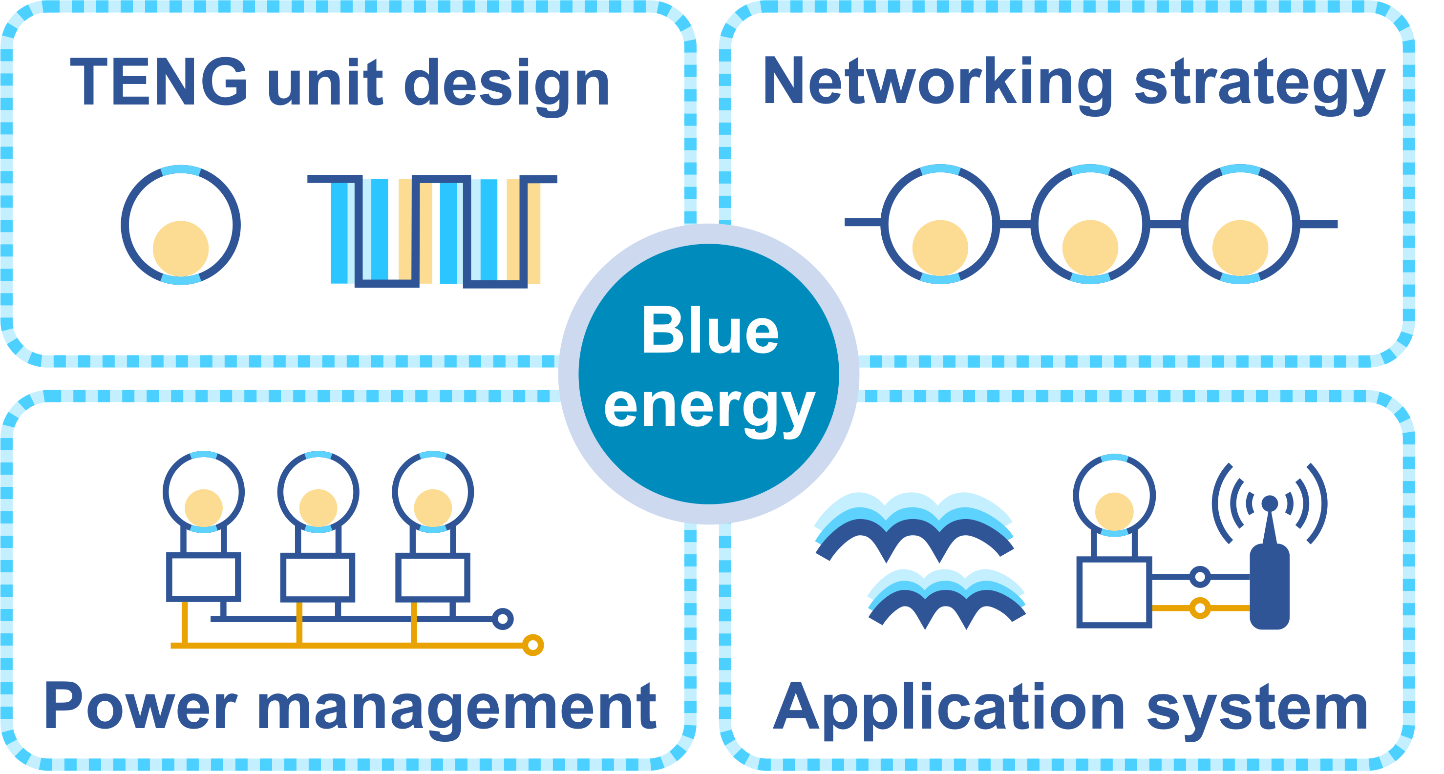
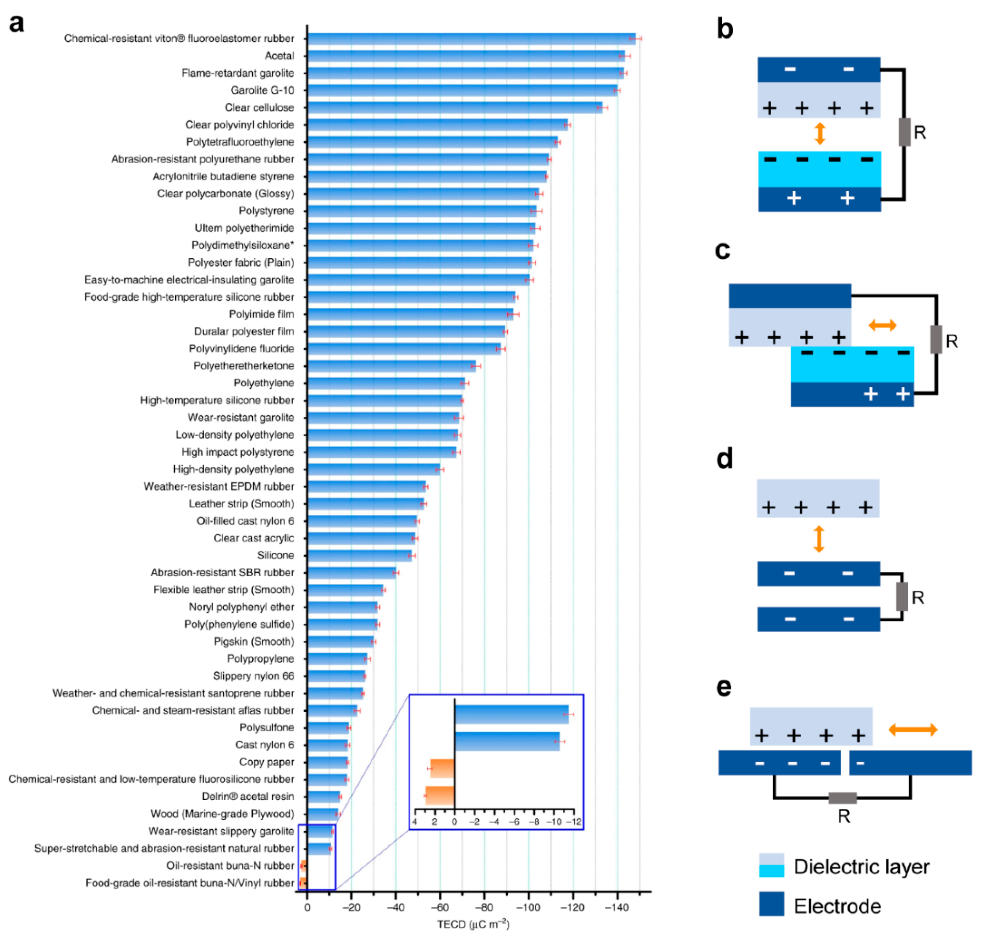
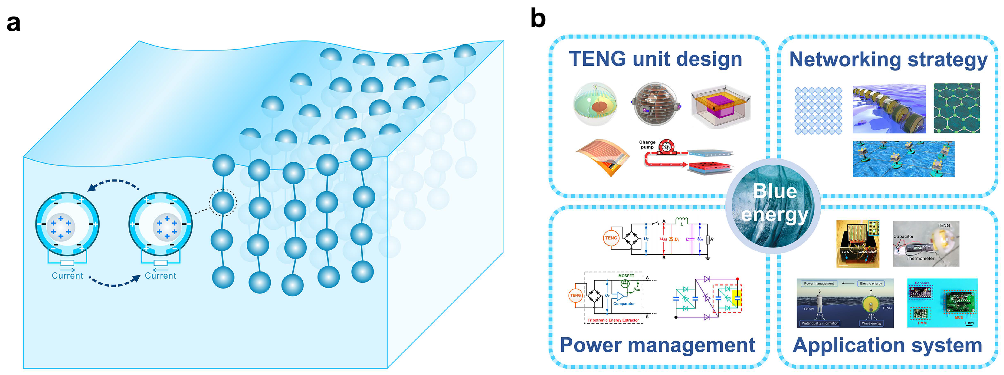
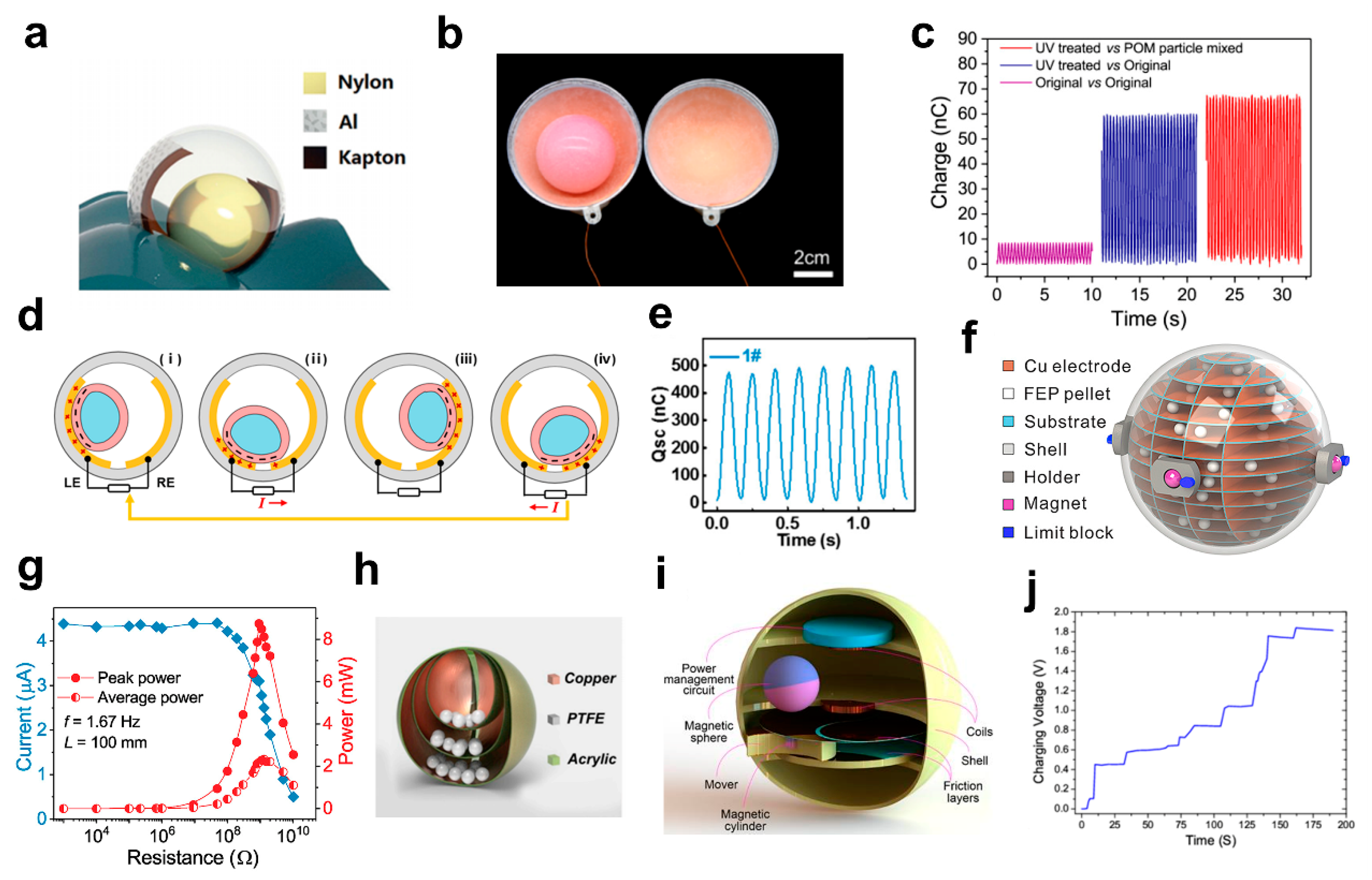
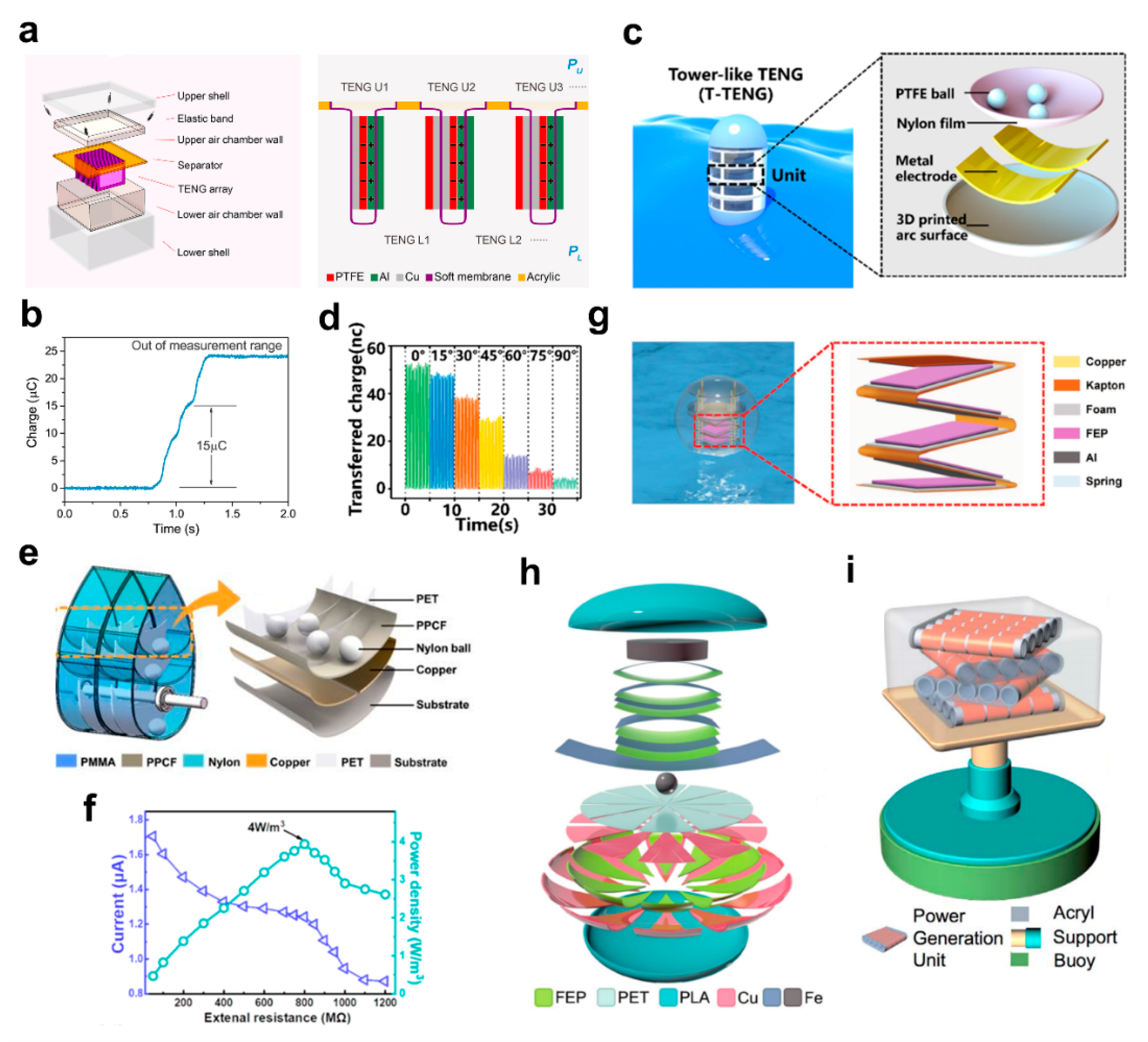
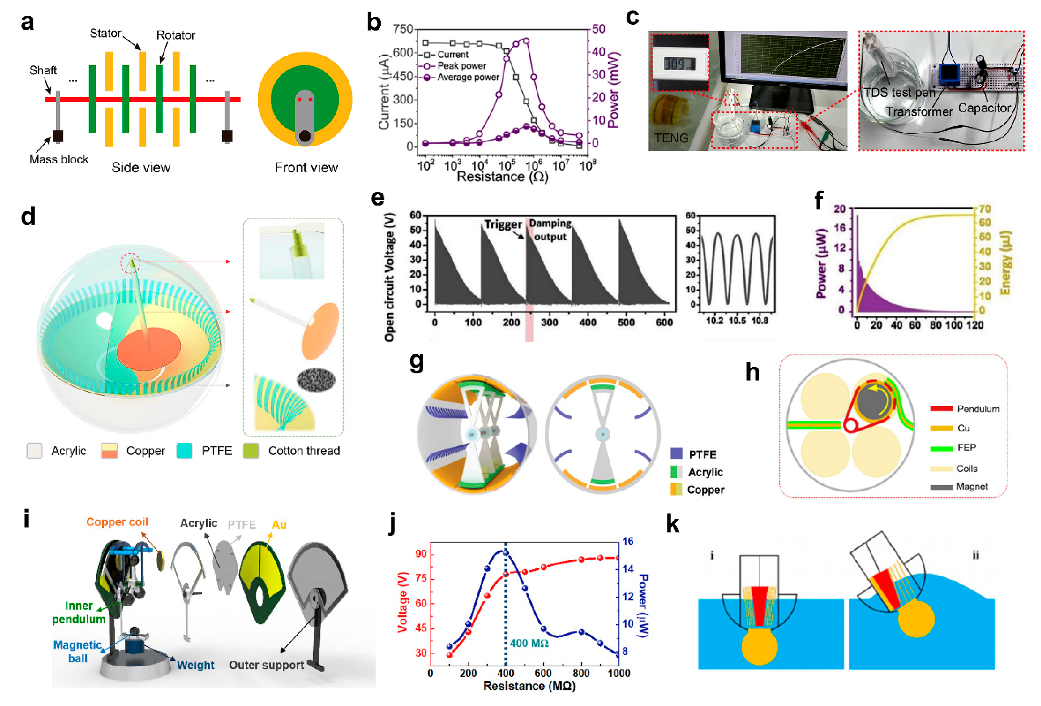
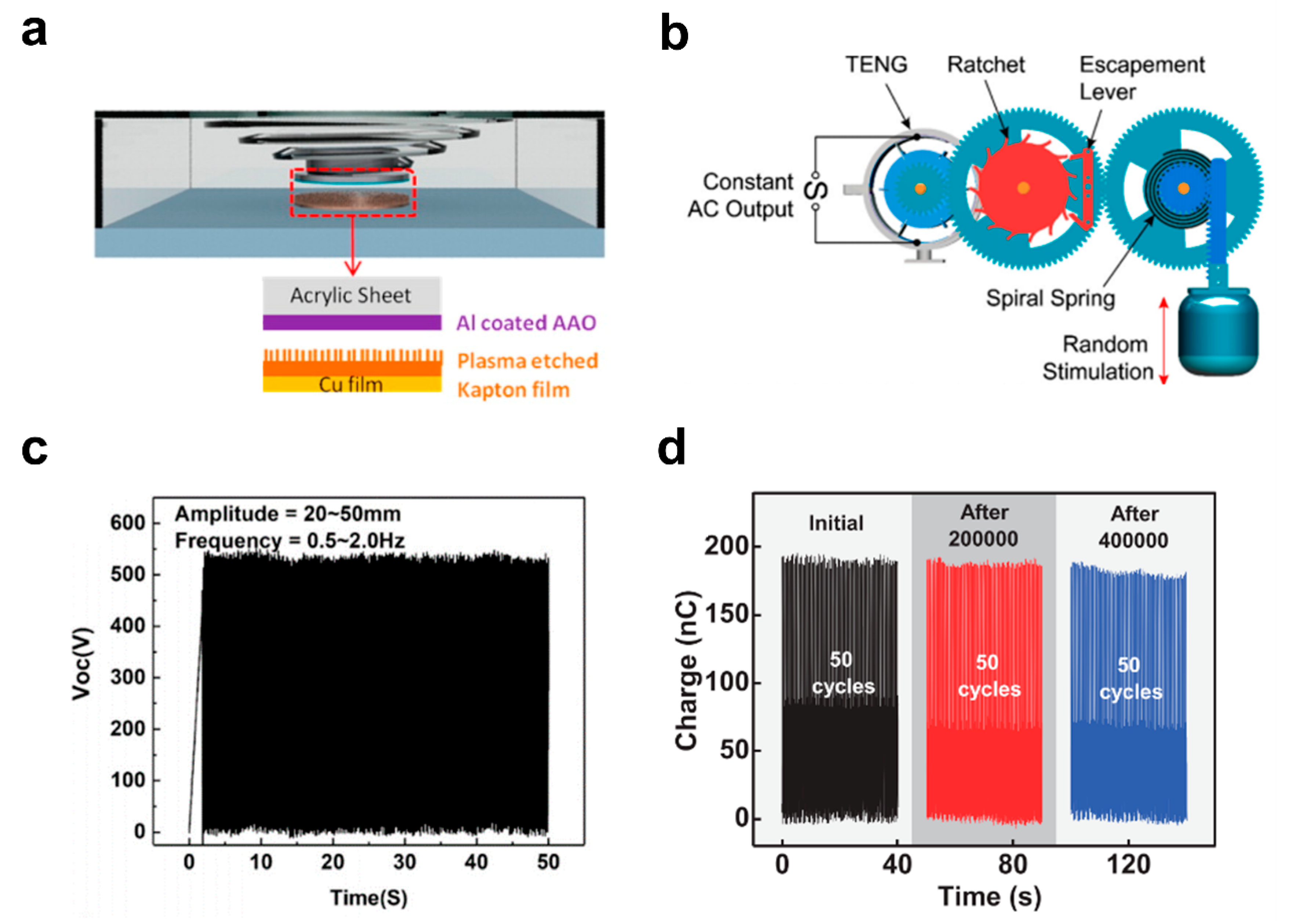
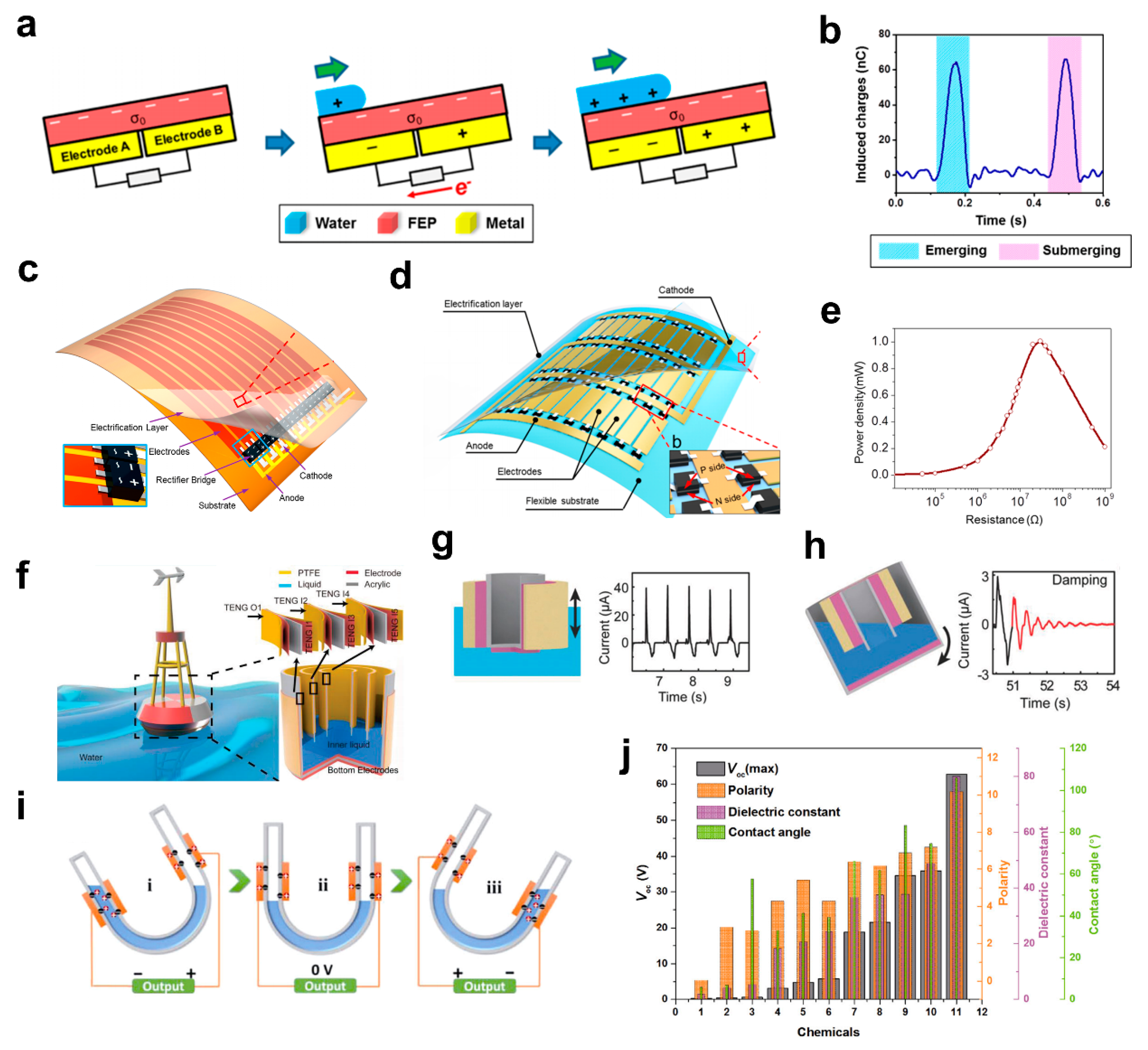
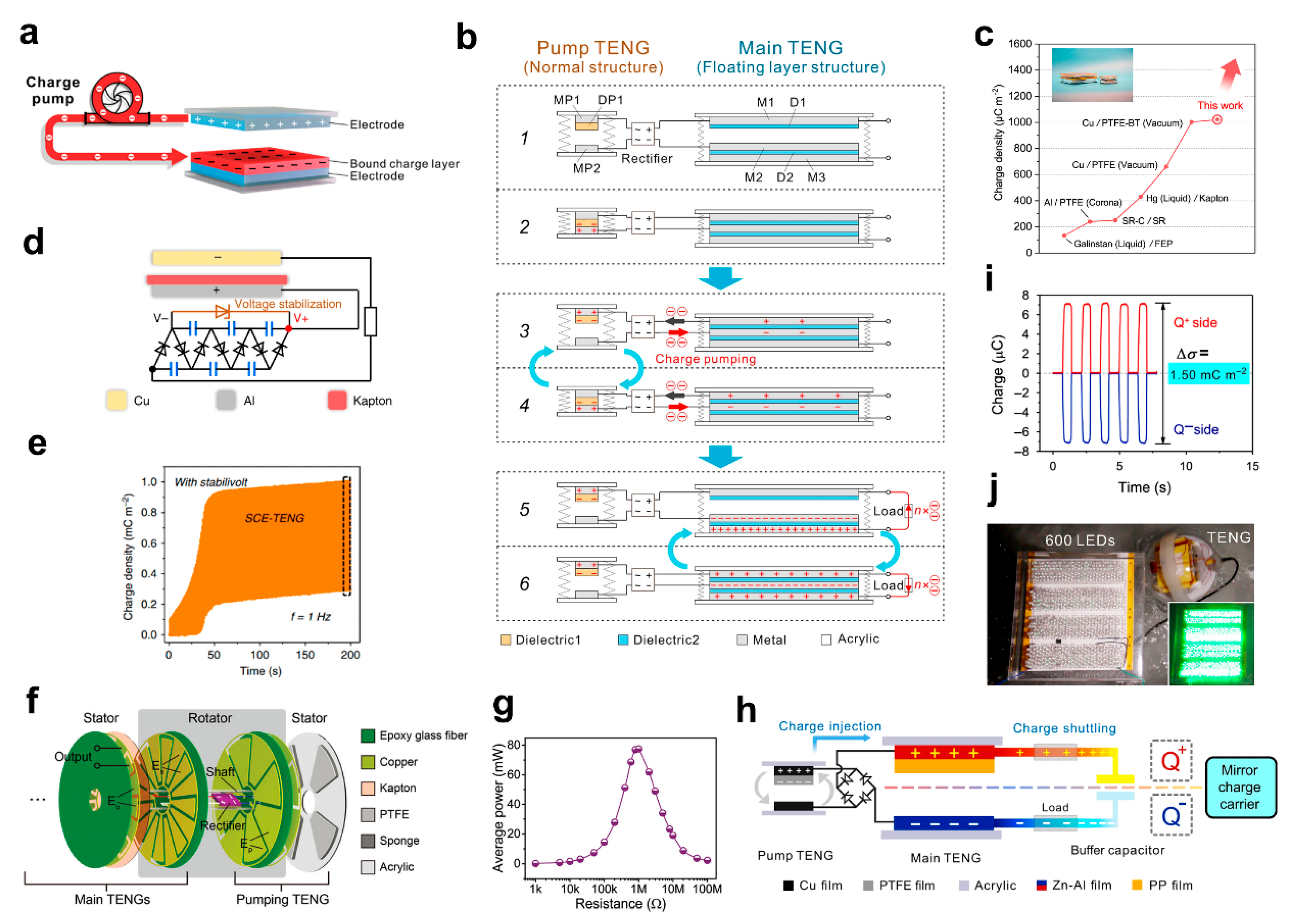
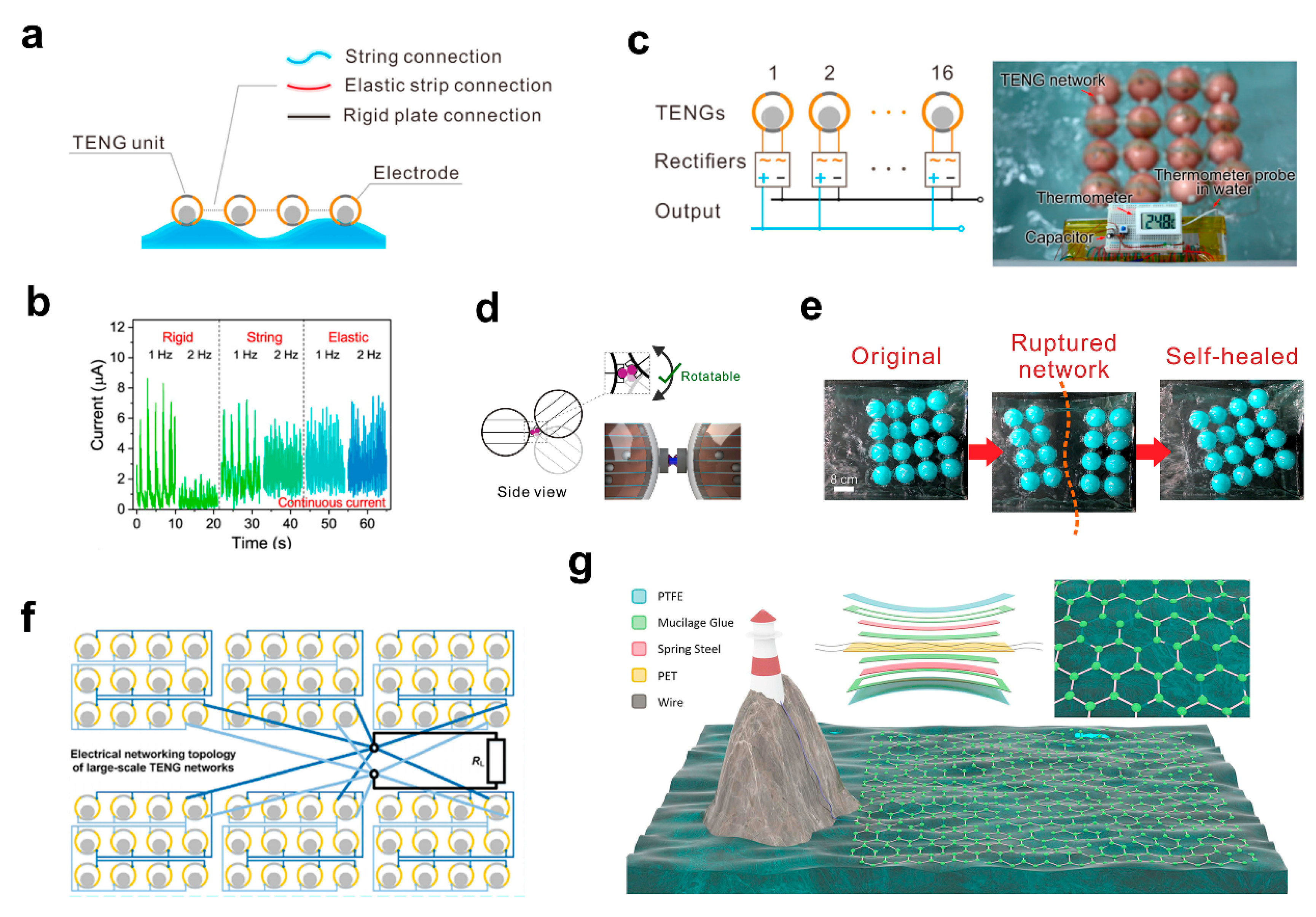
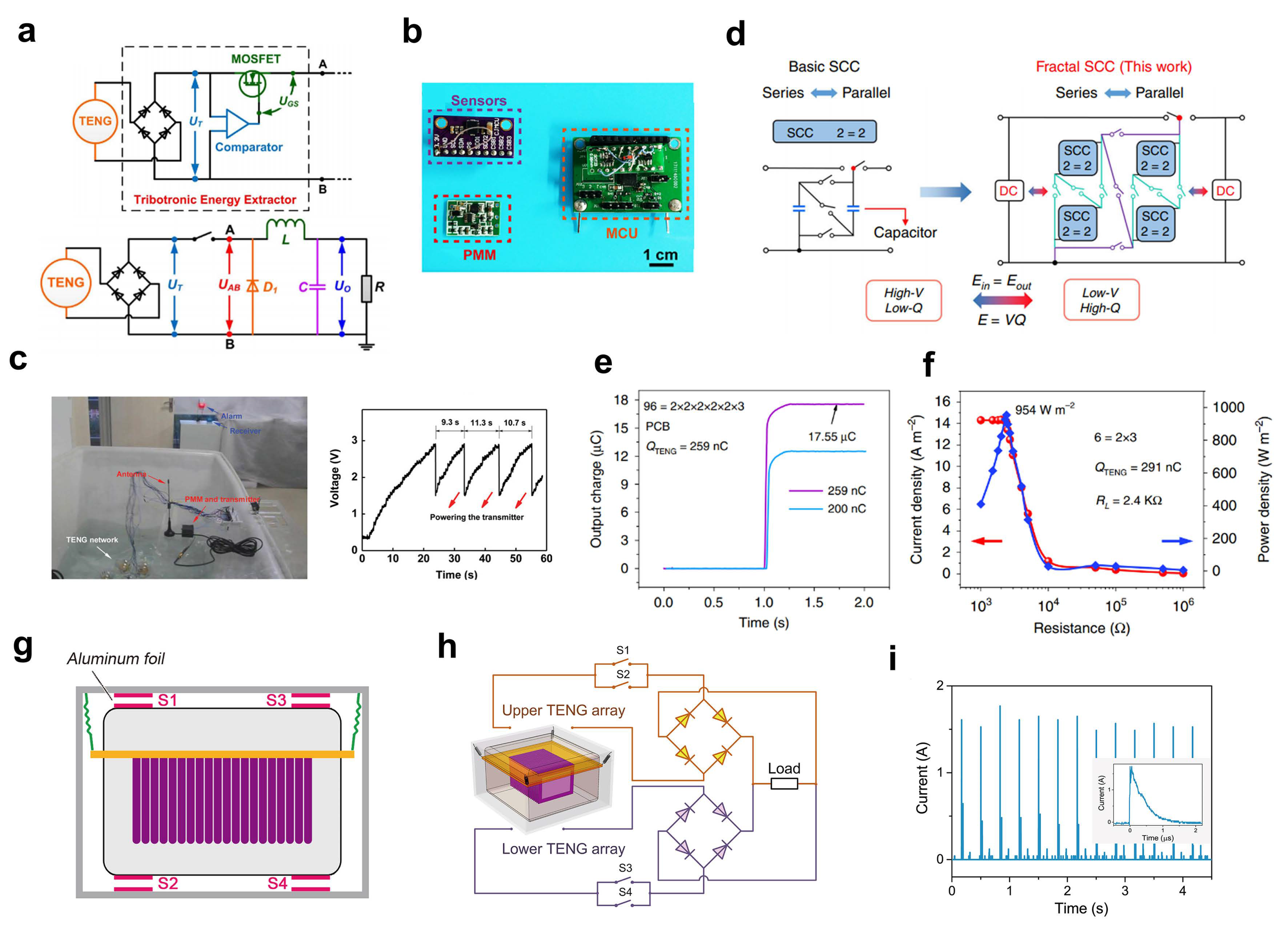
Table 1.
Summary of typical TENG units.
| Device | Feature | Typical Output | Dimension Per Unit | Material | Mode | Year | Note | |||
|---|---|---|---|---|---|---|---|---|---|---|
| Qsc | Isc | Power | Power Density | |||||||
| rolling-structured TENG [53] (RF-TENG) | rolling | 24 nC (wave, 1.43 Hz) | 1.2 µA (wave, 1.43 Hz) | sphere diameter 6 cm | Nylon, Al, Kapton | freestanding | 2015 | low friction | ||
| ball-shell-structured TENG [54] (BS-TENG) | rolling | 72.6 nC (motor) | 1.8 μA (motor, 3 Hz) | peak: 1.28 mW (motor, 5 Hz) average: 0.31 mW (motor, 5 Hz) | peak: 7.13 W m−3 (motor, 5 Hz) average: 1.73 W m−3 (motor, 5 Hz) | sphere diameter 7 cm | silicon rubber, POM, Ag-Cu | freestanding | 2018 | low damping force |
| 3D electrode TENG [42] | rolling, multilayer | 0.52 μC (motor) | 5 μA (motor, 2 Hz) | peak: 8.75mW (motor, 1.67 Hz) average: 2.33 mW (motor, 1.67 Hz) | peak: 32.6 W m−3 (motor, 1.67 Hz) average: 8.69 W m−3 (motor, 1.67 Hz) 2.05 W m−3 (wave) | sphere diameter 8 cm | FEP, Cu | freestanding | 2019 | enhanced contact area |
| air-driven membrane structure TENG [43] | multilayer, mass-spring | 15 μC (rectified, motor) | 187 μA (motor) 1.77 A (contact switch) | peak: 10 mW (motor) 313 W (contact switch) | peak: 13.23 W m−3 (motor, core device) | rectangular inner part: 12 cm × 9 cm | PTFE, soft membrane, Al, Cu | contact separation | 2017 | high output |
| spring-assisted spherical TENG [61] | multilayer, mass-spring | 0.67 µC | 120 µA | peak: 7.96 mW | peak: 15.2 W m−3 | sphere diameter 10 cm | Kapton, FEP, spring, Cu, Al | contact separation | 2018 | |
| nodding duck structure multi-track TENG [60] (NDM-FTENG) | multilayer, rolling | ∼1.1 μA (two devices, wave) | peak: 4 W m−3 (motor, 0.21 Hz) | 10 cm × 20 cm (width by height) | PPCF (PVDF/PDMS composite films), nylon, Cu, PET, PMMA | freestanding | 2021 | |||
| tandem disk TENG [46] (TD-TENG) | grating, pendulum, multilayer | 3.3 μC (wave, 0.58 Hz) | peak: 45.0 mW (wave, 0.58 Hz) average: 7.5 mW (wave, 0.58 Hz) | peak: 7.89 W m−3 (wave, 0.58 Hz) average: 1.3 W m−3 (wave, 0.58 Hz) 7.3 W m−3 (wave, 0.58 Hz, core device) | volume 0.0057 m3 | PTFE, acrylic, Cu | freestanding | 2019 | high power density | |
| single pendulum inspired TENG (P-TENG) [41] | pendulum, spacing | 18.2 nC (motor, 0.017 Hz) | sphere diameter 13 cm | PTFE, Cu, acrylic, cotton thread | freestanding | 2019 | durable | |||
| robust swing-structured TENG [63] (SS TENG) | pendulum, spacing | 256 nC (wave, 1.2 Hz) | 5.9 µA (wave, 1.2 Hz) | peak: 4.56 mW (motor, 0.017 Hz) | peak: 1.29 W m−3 (motor, 0.017 Hz) | cylindrical shell: length 20 cm, outer diameter 15 cm | PTFE, Cu, acrylic | freestanding | 2020 | durable |
| active resonance TENG [66] (AR-TENG) | pendulum, multilayer | 0.55 μC (wave) | 120 μA (wave) | peak: 12.3 mW (wave) | peak: 16.31 W m−3 (wave, core device) | volume 754 cm3 (core device) | FEP, Kapton, Cu | contact separation | 2021 | omnidirectional |
| spiral TENG [67] | mass-spring | 15 μA (wave) | peak: 2.76 W m−2 (motor, 30 Hz) | sphere diameter 14 cm | Kapton, Cu, Al | contact separation | 2013 | |||
| liquid solid electrification enabled generator [51] (LSEG) | L-S contact | 75 nC (motor, 0.5 m/s) | 3 μA (motor, 0.5 m/s) | average: 0.12 mW (motor, 0.5 m/s) | average: 0.067 W m−2 (motor, 0.5 m/s) | planar: 6 cm × 3 cm | water, FEP, Cu | freestanding | 2014 | |
| networked integrated TENG [69] (NI-TENG) | L-S contact | 13.5 μA (motor, 0.5 m/s) | peak: 1.03 mW (motor, 0.5 m/s) | peak: 0.147 W m−2 (motor, 0.5 m/s) | planar: 10 cm × 7 cm | Kapton, PTFE, water | freestanding | 2018 | ||
| TENG based on charge shuttling [52] (CS-TENG) | charge pumping, multilayer | 53 μC (rectified, wave, 0.625 Hz) | 1.3 mA (wave, 0.625 Hz) | peak: 126.67 mW (wave, 0.625 Hz) | peak: 30.24 W m−3 (wave, 0.625 Hz) | sphere diameter 20 cm | PTFE, PP, Cu, Zn-Al | contact separation | 2020 | high charge output |
Publisher’s Note: MDPI stays neutral with regard to jurisdictional claims in published maps and institutional affiliations. |
© 2021 by the authors. Licensee MDPI, Basel, Switzerland. This article is an open access article distributed under the terms and conditions of the Creative Commons Attribution (CC BY) license (https://creativecommons.org/licenses/by/4.0/).
Share and Cite
MDPI and ACS Style
Wang, H.; Xu, L.; Wang, Z. Advances of High-Performance Triboelectric Nanogenerators for Blue Energy Harvesting. Nanoenergy Adv. 2021, 1, 32-57. https://0-doi-org.brum.beds.ac.uk/10.3390/nanoenergyadv1010003
AMA Style
Wang H, Xu L, Wang Z. Advances of High-Performance Triboelectric Nanogenerators for Blue Energy Harvesting. Nanoenergy Advances. 2021; 1(1):32-57. https://0-doi-org.brum.beds.ac.uk/10.3390/nanoenergyadv1010003
Chicago/Turabian StyleWang, Huamei, Liang Xu, and Zhonglin Wang. 2021. "Advances of High-Performance Triboelectric Nanogenerators for Blue Energy Harvesting" Nanoenergy Advances 1, no. 1: 32-57. https://0-doi-org.brum.beds.ac.uk/10.3390/nanoenergyadv1010003