
A Near-Zero Power Triboelectric Wake-Up System for Autonomous Beaufort Scale of Wind Force Monitoring

Abstract
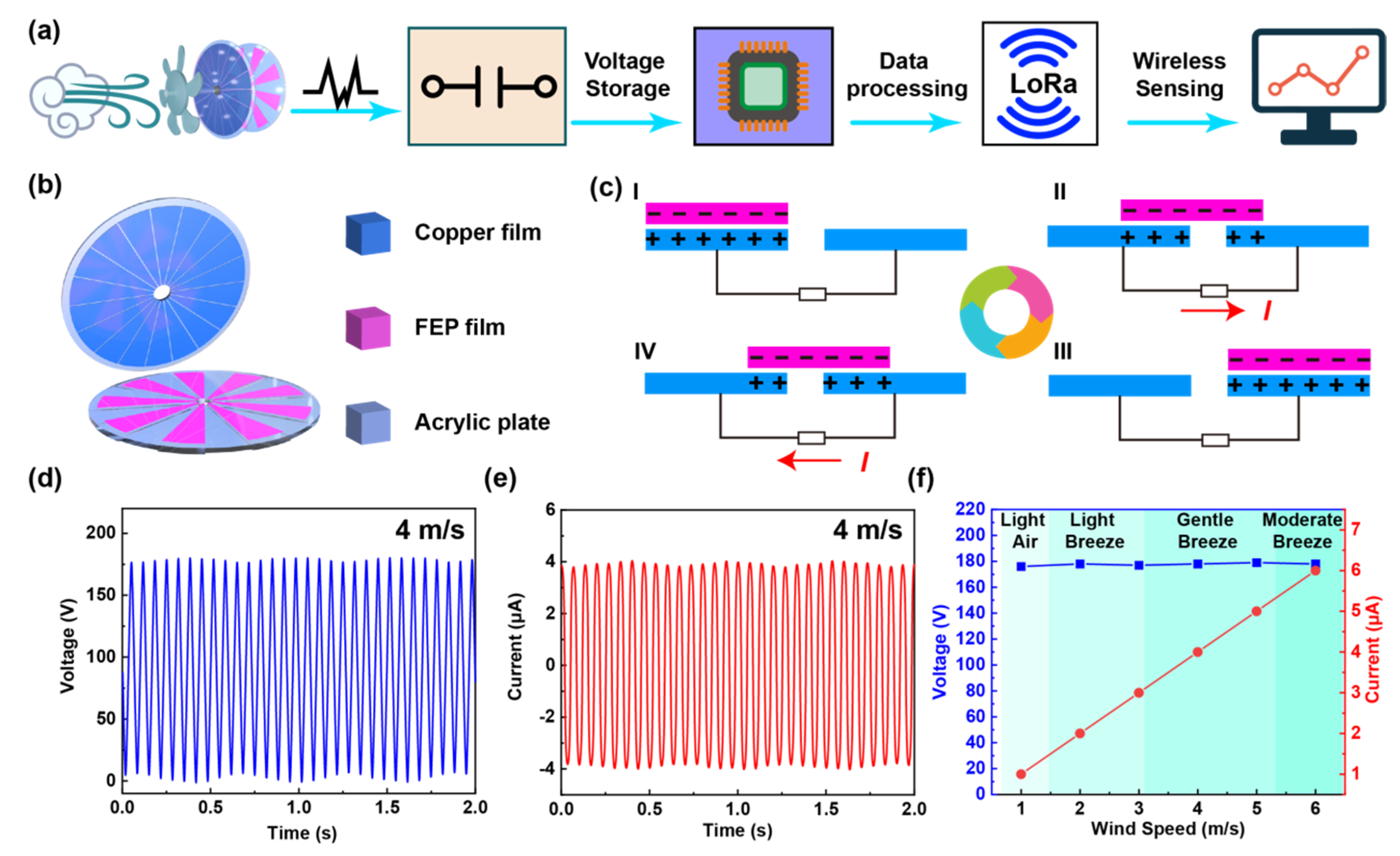
:
1. Introduction
2. System Design and Characterization
2.1. Design of the System Framework
2.2. Structure and Characteristics of the Rotating TENG
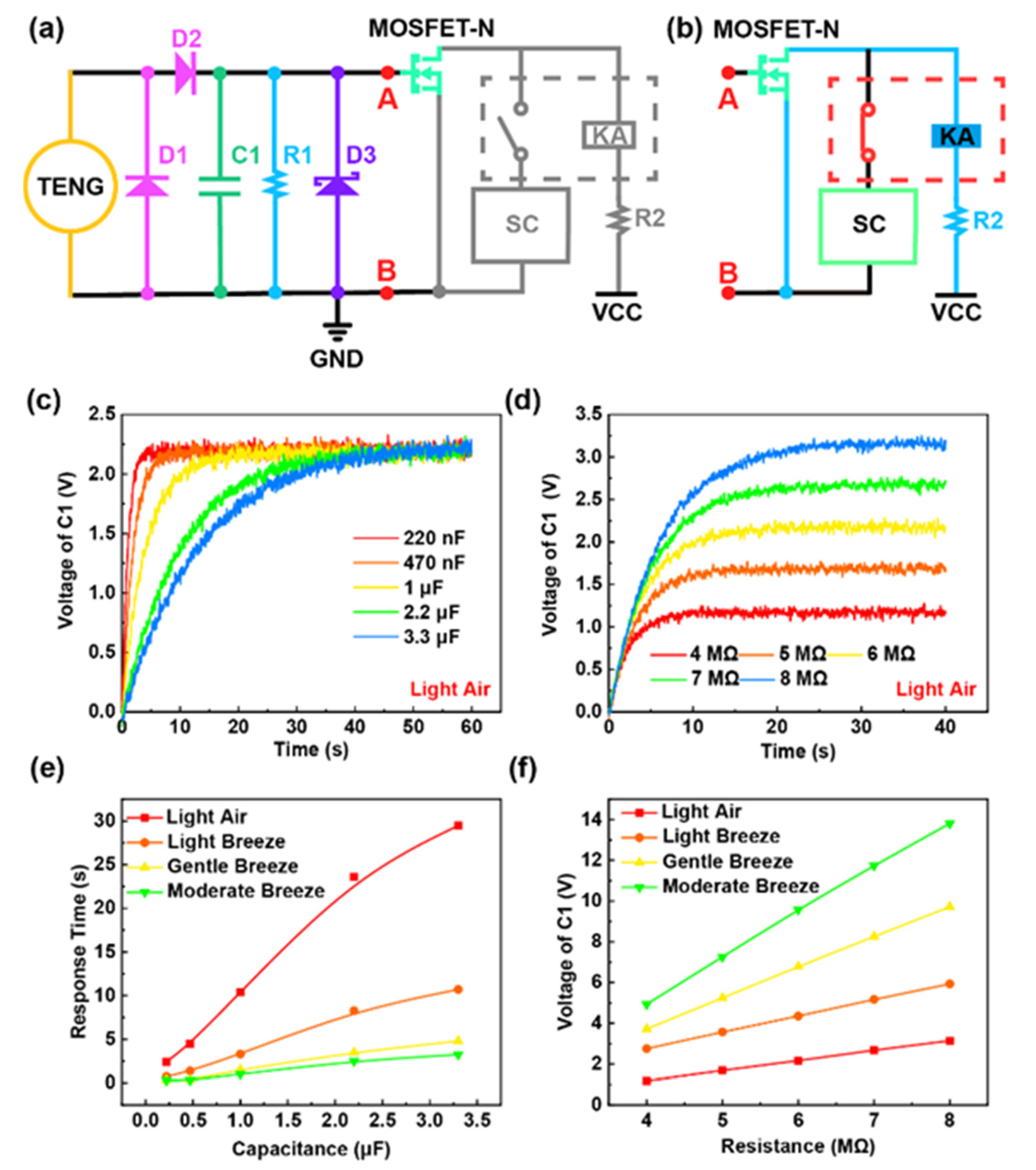
2.3. Mechanism and Characteristics of the Wake-Up Circuit
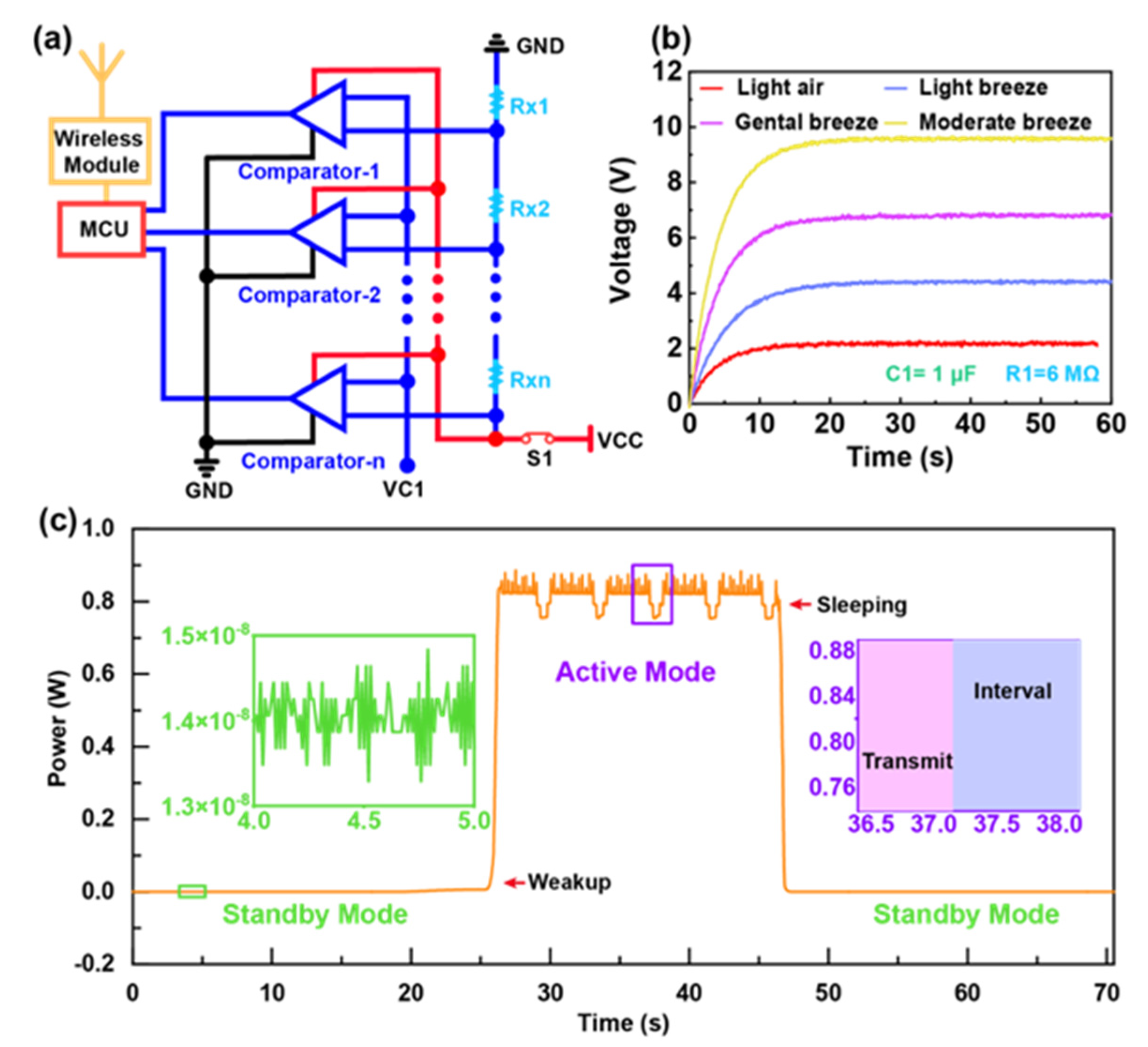
2.4. Mechanism and Characteristics of the Stage Circuit (SC)
3. The Result and Discussion
3.1. The Power Consumption of the Wake-Up System
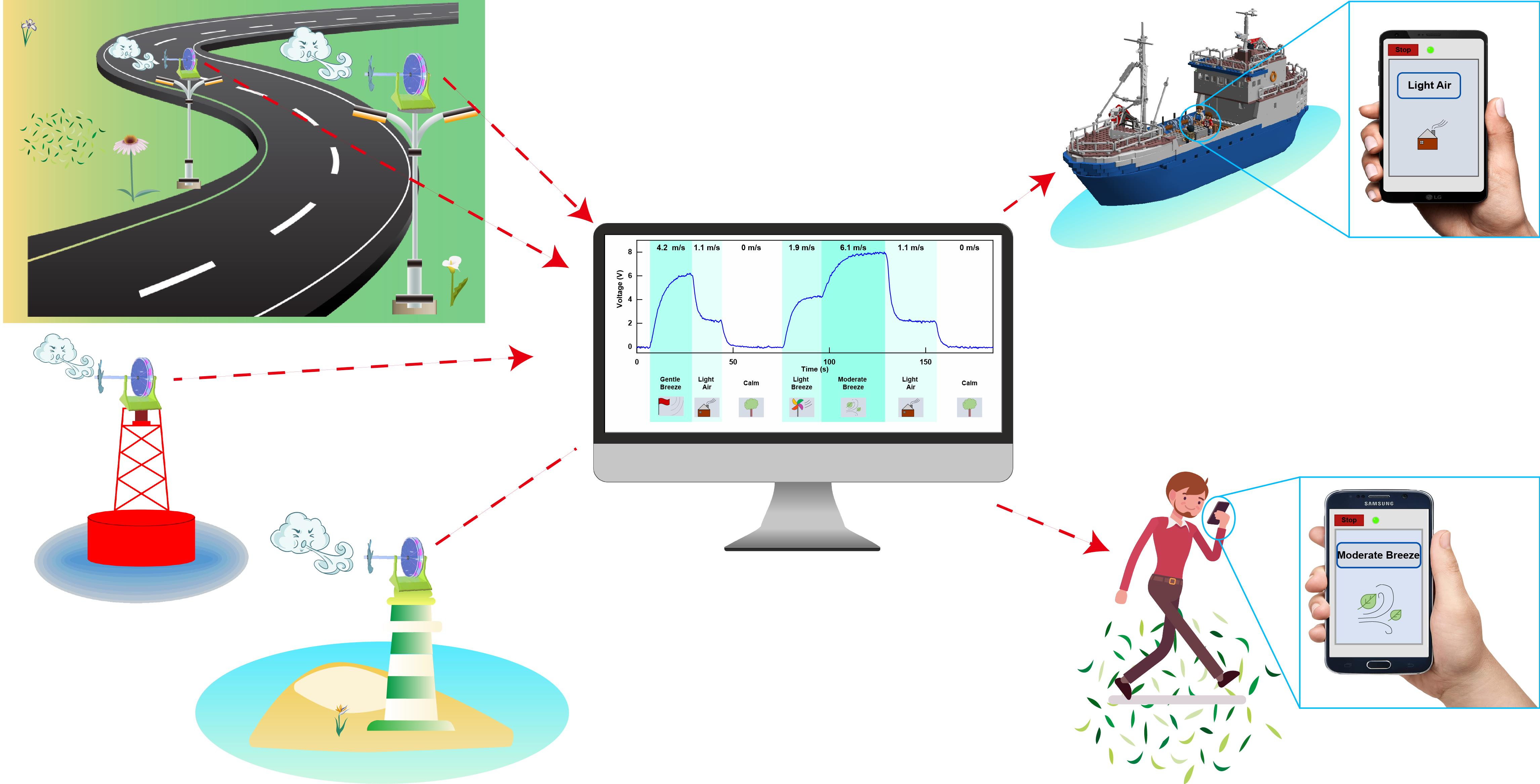
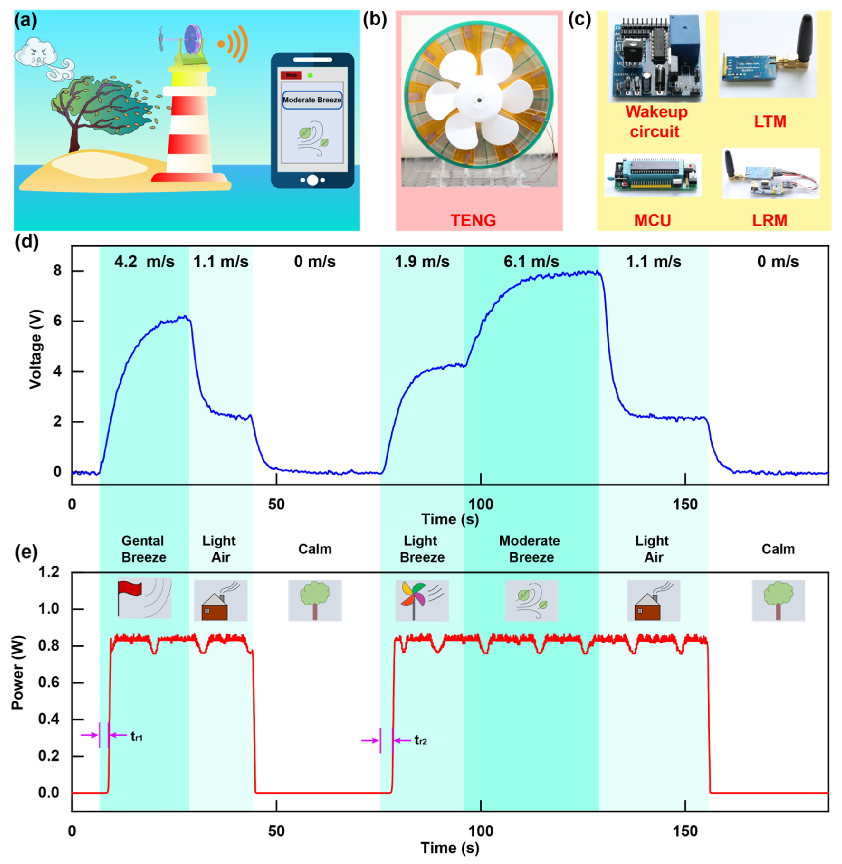
3.2. Demonstration of Beaufort Scale of Wind Force Monitoring
4. Experimental Section
5. Conclusions
Supplementary Materials
Author Contributions
Funding
Data Availability Statement
Conflicts of Interest
References
- Kusiak, A.; Zhang, Z.; Verma, A. Prediction, operations, and condition monitoring in wind energy. Energy 2013, 60, 1–12. [Google Scholar] [CrossRef]
- Olsson, R.H.; Bogoslovov, R.B.; Gordon, C. Event Driven Persistent Sensing: Overcoming the Energy and Lifetime Limitations in Unattended Wireless Sensors. In Proceedings of the 2016 IEEE SENSORS, Orlando, FL, USA, 30 Octocber–3 November 2016; pp. 1–3. [Google Scholar]
- Bassirian, P.; Moody, J.; Bowers, S.M. Event-Driven Wakeup Receivers: Applications and Design Challenges. In Proceedings of the 2017 IEEE 60th International Midwest Symposium on Circuits and Systems (MWSCAS), Boston, UK, 6–9 August 2017; pp. 1324–1327. [Google Scholar]
- Hassanalieragh, M.; Soyata, T.; Nadeau, A.; Sharma, G. UR-SolarCap: An Open Source Intelligent Auto-Wakeup Solar Energy Harvesting System for Supercapacitor-Based Energy Buffering. IEEE Access 2017, 4, 542–557. [Google Scholar] [CrossRef]
- Sanchez, A.; Aguilar, J.; Blanc, S.; Serrano, J.J. RFID-based wake-up system for wireless sensor networks. Proc. Spie 2011, 8067, 8–12. [Google Scholar]
- Kpuska, V.Z.; Eljhani, M.M.; Hight, B.H. Front-end of Wake-Up-Word Speech Recognition System Design on FPGA. J. Telecommun. Syst. Manage. 2013, 2, 1000108. [Google Scholar]
- Yen, W.C.; Chen, H.W. Low power and fast system wakeup circuit. IEE Proc. Circuits Devices Syst. 2005, 152, 223–228. [Google Scholar] [CrossRef]
- Reger, R.W.; Barney, B.; Yen, S.; Satches, M.; Griffin, B.A. Near-Zero Power Accelerometer Wakeup System. In Proceedings of the 2017 IEEE SENSORS, Glasgow, UK, 29 Octocber–1 November 2017; pp. 1–3. [Google Scholar]
- Reger, R.W.; Clews, P.J.; Bryan, G.M.; Keane, C.A.; Henry, M.D.; Griffin, B.A. Aluminum Nitride Piezoelectric Microphones as Zero-Power Passive Acoustic Filters. In Proceedings of the 19th International Conference on Solid-State Sensors, Actuators and Microsystems (TRANSDUCERS), Kaohsiung, Taiwan, 18–22 June 2017; pp. 2207–2210. [Google Scholar]
- Vivekananthan, V.; Chandrasekhar, A.; Alluri, N.R.; Purusothaman, Y.; Khandelwal, G.; Pandey, R.; Kima, S.-J. Fe2O3 magnetic particles derived triboelectric-electromagnetic hybrid generator for zero-power consuming seismic detection—ScienceDirect. Nano Energy 2019, 64, 103926. [Google Scholar] [CrossRef]
- Vivekananthan, V.; Chandrasekhar, A.; Alluri, N.R.; Purusothaman, Y.; Kim, S.-J. A highly reliable, impervious and sustainable triboelectric nanogenerator as a zero-power consuming active pressure sensor. Nanoscale Adv. 2020, 2, 746–754. [Google Scholar] [CrossRef]
- Zhang, C.; Dai, K.; Liu, D.; Yi, F.; You, Z. Ultralow Quiescent Power-Consumption Wake-Up Technology Based on the Bionic Triboelectric Nanogenerator. Adv. Sci. 2020, 7, 2000254. [Google Scholar] [CrossRef] [PubMed]
- Wang, S.; Lin, L.; Wang, Z.L. Nanoscale triboelectric-effect-enabled energy conversion for sustainably powering portable electronics. Nano Lett. 2012, 12, 6339–6346. [Google Scholar] [CrossRef] [PubMed] [Green Version]
- Wang, Z.L. On Maxwell’s displacement current for energy and sensors: The origin of nanogenerators. Mater. Today 2017, 20, 74–82. [Google Scholar] [CrossRef]
- Zhou, Y.S.; Wang, S.; Yang, Y.; Zhu, G.; Niu, S.; Lin, Z.H.; Liu, Y.; Wang, Z.L. Manipulating Nanoscale Contact Electrification by an Applied Electric Field. Nano Lett. 2014, 14, 1567–1572. [Google Scholar] [CrossRef] [Green Version]
- Chen, J.; Huang, Y.; Zhang, N.; Zou, H.; Liu, R.; Tao, C.; Fan, X.; Wang, Z.L. Micro-cable structured textile for simultaneously harvesting solar and mechanical energy. Nat. Energy 2016, 1, 16138. [Google Scholar] [CrossRef]
- Niu, S.; Ying, L.; Wang, S.; Long, L.; Yu, S.Z.; Hu, Y.; Zhong, L.W. Theoretical Investigation and Structural Optimization of Single-Electrode Triboelectric Nanogenerators. Adv. Funct. Mater. 2014, 24, 3332–3340. [Google Scholar] [CrossRef]
- Zhu, G.; Chen, J.; Liu, Y.; Bai, P.; Zhou, Y.S.; Jing, Q.; Pan, C.; Wang, Z.L. Linear-Grating Triboelectric Generator Based on Sliding Electrification. Nano Lett. 2013, 13, 2282–2289. [Google Scholar] [CrossRef] [PubMed]
- Guo, T.; Zhao, J.; Liu, W.; Liu, G.; Pang, Y.; Bu, T.; Xi, F.; Zhang, C. Self-Powered Hall Vehicle Sensors Based on Triboelectric Nanogenerators. Adv. Mater. Technol. 2018, 3, 1800140. [Google Scholar] [CrossRef]
- Liu, D.; Chen, B.; An, J.; Li, C.; Liu, G.; Shao, J.; Tang, W.; Zhang, C.; Wang, Z.L. Wind-driven self-powered wireless environmental sensors for Internet of Things at long distance. Nano Energy 2020, 73, 104819. [Google Scholar] [CrossRef]
- Wang, Z.L. Triboelectric Nanogenerators as New Energy Technology for Self-Powered Systems and as Active Mechanical and Chemical Sensors. ACS Nano 2013, 7, 9533–9557. [Google Scholar] [CrossRef]
- Rong, X.; Zhao, J.; Guo, H.; Zhen, G.; Dong, G. Material Recognition Sensor Array by Electrostatic Induction and Triboelectric Effects. Adv. Mater. Technol. 2020, 5, 2000641. [Google Scholar] [CrossRef]
- Liu, W.; Xu, L.; Liu, G.; Yang, H.; Bu, T.; Fu, X.; Xu, S.; Fang, C.; Zhang, C. Network topology optimization of triboelectric nanogenerators for effectively harvesting ocean wave energy. Iscience 2020, 23, 101848. [Google Scholar] [CrossRef] [PubMed]
- Jiang, D.; Liu, G.; Li, W.; Bu, T.; Wang, Y.; Zhang, Z.; Pang, Y.; Xu, S. A leaf-shaped triboelectric nanogenerator for multiple ambient mechanical energy harvesting. IEEE Trans. Power Electron. 2019, 35, 25–32. [Google Scholar] [CrossRef]
- Quan, Z.; Han, C.B.; Jiang, T.; Wang, Z.L. Wind Energy: Robust Thin Films-Based Triboelectric Nanogenerator Arrays for Harvesting Bidirectional Wind Energy. Adv. Energy Mater. 2016, 6, 1501799. [Google Scholar] [CrossRef]
- Yang, Y.; Zhu, G.; Zhang, H.; Chen, J.; Zhong, X.; Lin, Z.H.; Su, Y.; Bai, P.; Wen, X.; Wang, Z.L. Triboelectric nanogenerator for harvesting wind energy and as self-powered wind vector sensor system. Acs Nano 2013, 7, 9461–9468. [Google Scholar] [CrossRef]
- Bi, M.; Wu, Z.; Wang, S.; Cao, Z.; Ye, X. Optimization of structural parameters for rotary freestanding-electret generators and wind energy harvesting. Nano Energy 2020, 75, 104968. [Google Scholar] [CrossRef]
- Wang, J.; Ding, W.; Pan, L.; Wu, C.; Yu, H.; Yang, L.; Liao, R.; Wang, Z.L. Self-Powered Wind Sensor System for Detecting Wind Speed and Direction Based on a Triboelectric Nanogenerator. ACS Nano 2018, 12, 3954–3963. [Google Scholar] [CrossRef] [PubMed]
- Wang, P.; Lun, P.; Wang, J.; Xu, M.; Dai, G.; Zou, H.; Dong, K.; Wang, Z.L. An Ultra-Low-Friction Triboelectric-Electromagnetic Hybrid Nanogenerator for Rotation Energy Harvesting and Self-Powered Wind Speed Sensor. ACS Nano 2018, 12, 9433–9440. [Google Scholar] [CrossRef] [PubMed]
- Shan, L.; Gao, L.; Chen, X.; Tong, D.; Yu, H. Simultaneous energy harvesting and signal sensing from a single triboelectric nanogenerator for intelligent self-powered wireless sensing systems. Nano Energy 2020, 75, 104813. [Google Scholar]
- Fu, X.; Bu, T.; Li, C.; Liu, G.; Zhang, C. Overview of micro/nano wind energy harvesters and sensors. Nanoscale 2020, 12, 23929–23944. [Google Scholar] [CrossRef] [PubMed]


Publisher’s Note: MDPI stays neutral with regard to jurisdictional claims in published maps and institutional affiliations. |
© 2021 by the authors. Licensee MDPI, Basel, Switzerland. This article is an open access article distributed under the terms and conditions of the Creative Commons Attribution (CC BY) license (https://creativecommons.org/licenses/by/4.0/).
Share and Cite
Tong, T.; Liu, G.; Lin, Y.; Xu, S.; Zhang, C. A Near-Zero Power Triboelectric Wake-Up System for Autonomous Beaufort Scale of Wind Force Monitoring. Nanoenergy Adv. 2021, 1, 121-130. https://0-doi-org.brum.beds.ac.uk/10.3390/nanoenergyadv1020006
Tong T, Liu G, Lin Y, Xu S, Zhang C. A Near-Zero Power Triboelectric Wake-Up System for Autonomous Beaufort Scale of Wind Force Monitoring. Nanoenergy Advances. 2021; 1(2):121-130. https://0-doi-org.brum.beds.ac.uk/10.3390/nanoenergyadv1020006
Chicago/Turabian StyleTong, Tong, Guoxu Liu, Yuan Lin, Shaohang Xu, and Chi Zhang. 2021. "A Near-Zero Power Triboelectric Wake-Up System for Autonomous Beaufort Scale of Wind Force Monitoring" Nanoenergy Advances 1, no. 2: 121-130. https://0-doi-org.brum.beds.ac.uk/10.3390/nanoenergyadv1020006